Abstract
BACKGROUND AND PURPOSE: The inferior petrosal sinus (IPS) is the main transvenous access route used to examine or treat lesions involving the cavernous sinus. To carry out these procedures successfully, one must have a detailed knowledge of the anatomy of the venous system around the junction of the IPS and the internal jugular vein (IJV).
MATERIALS AND METHODS: Eighty-three sides in 63 patients (26 men, 37 women; mean, 56.5 years of age) were examined by using 3D rotational venography (3DRV).
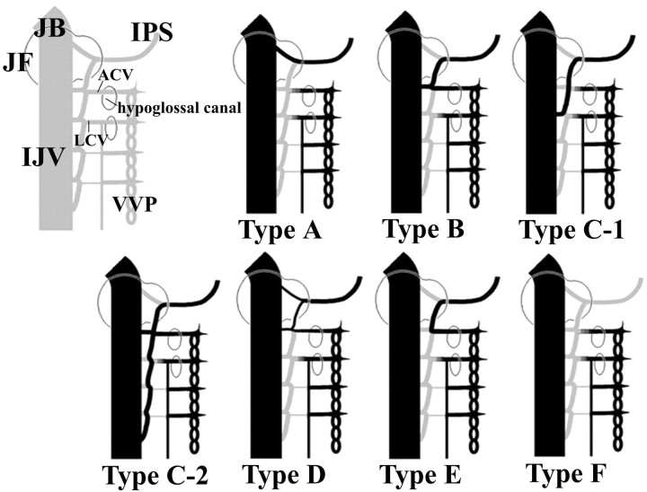
RESULT: The drainage patterns of the IPS could be classified into the following 6 types, with emphasis on the level of IPS-IJV junction: type A, the IPS drains into the jugular bulb in 1/83 sides (1.2%); type B, the IPS drains into the IJV at the level of the extracranial opening of the hypoglossal canal in 29/83 sides (34.9%); type C, the IPS drains into the lower extracranial IJV in 31/83 sides (37.3%); type D, the IPS forms a plexus and has multiple junctions to the IJV near the jugular foramen in 5/83 sides (6.0%); type E, the IPS drains directly into the vertebral venous plexus (VVP) with no connection to the IJV in 3/83 sides (3.6%); and type F, the IPS is absent in 14/83 sides (16.9%). Each type is also characterized by the way of anastomosis with the VVP.
CONCLUSION: This classification seemed to be rational from the embryologic viewpoint, and it may be useful in establishing treatment strategies that involve endovascular manipulation via the IPS.
The inferior petrosal sinus (IPS) is a dural venous sinus running along the intracranial surface of the petroclivial fissure, connecting the posterior aspect of the ipsilateral cavernous sinus with the internal jugular vein (IJV). In the studies of cadaveric dissection,1,2 it is reported that the IPS has numerous anastomoses with surrounding veins, the major one being that of the vertebral venous plexus (VVP). The IPS is also an important transvenous access route in the treatment of dural arteriovenous fistula of the cavernous sinus and in cavernous sinus sampling for the diagnosis of pituitary adenoma. It is essential for these safe and effective interventions to be based on a detailed knowledge of the anatomy of the IPS-IJV junction.
In 1968, Shiu et al3 evaluated selective cavernous sinus venograms and classified IPS drainage into the jugular bulb (JB) into 4 types; Miller et al4,5 later performed re-evaluation. However, those were 2D assessments, which appear to be less than ideal for sufficient comprehension of 3D structures. In this report, we present morphologic variations observed in the IPS-IJV junction by 3D rotational venography (3DRV) and discuss findings from a developmental viewpoint. The 3DRV is a technique recently reported by Nishio et al,6 which is suitable for understanding the 3D venous system.
Materials and Methods
Study Patients
Sixty-three patients, 26 men and 37 women, 20–78 years of age (mean, 56.5 years of age) with intracranial disorders (unruptured cerebral aneurysms in 25, brain tumors in 30, and ischemic cerebrovascular diseases in 8) were examined between May 2003 and May 2005. Morphologic patterns of the IPS-IJV junction were assessed by using 3DRV in 83 sides (right, 46; left, 37) of those patients bilaterally or unilaterally.
3DRV Image Acquisition
The 3DRV was performed as described. As is done in cerebral angiography, 5F diagnostic catheters were introduced into the femoral arteries by the Seldinger technique and were placed in a common carotid artery or an internal carotid artery. Two sets of rotational imaging were performed at 40° per second through an arc of 200°, one for obtaining the mask images for digital subtraction and the other for obtaining contrasted images. Thirty frame images were taken per second, and 300 images in total were transmitted to a 3D workstation. Constructed 3D images were assessed with a 3D viewer system. The 3D images were ultimately assessed as volume-rendering images. In total, 10–18 mL of a contrast agent (Iopamiron 300, Nihon Schering, Osaka, Japan) was injected at the rate of 2.2–4 mL per second. The interval to the beginning of the opacified imaging after the contrast agent injection ranged from 6.5 to 7.5 seconds. At the Osaka City University Hospital, venograms were obtained with Clavis 2000 AG (Hitachi Medical, Chiba, Japan) and a flat-panel detector, PAXSCAN4030A (Varian Medical Systems, Salt Lake City, Utah); image assessment was performed with a 3D workstation, Clavis CBR (Hitachi Medical) and a 3D viewer system, M900QUADRA (Ziosoft, Tokyo, Japan). At Izumi Municipal Hospital, venograms were obtained with Integris Allura (Phillips Medical Systems, Best, the Netherlands) and assessed with a 3D workstation, Integris 3D-RA (Phillips Medical Systems) and a 3D viewer system, Octane (Silicon Graphics Computer Systems, Mountain View, Calif). To evaluate the relation to the skull and cervical spine, we superimposed 3DRV images on bone mask images taken for digital subtraction (Photoshop, Adobe Systems, San Jose, Calif) (Fig 1). Because the target was the intracranial venous system, the structures covered in this assessment were limited to the level of the atlas.
Fig 1.
A 3DRV superimposed on a 3D rotational osteogram shows the relationship of venous structures—IPS (arrow), ACV (arrowhead), LCV (asterisk)—to bony structures (skull and upper cervical spine).
Results
Anatomic Classification According to the Level of the IPS-IJV Junction
Single or multiple IPS-IJV junctions were observed in each case. Individual junctions were at the following levels: into the JB, into the IJV near the extracranial opening of the hypoglossal canal, and into the lower extracranial IJV. The drainage patterns of the IPS were classified into 6 types according to the level of the IPS-IJV junction:
Type A.
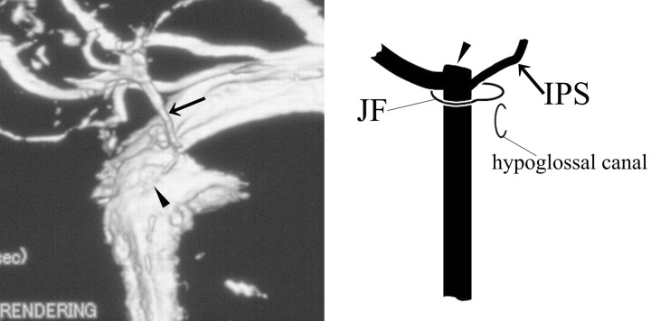
The IPS drains into the JB (Fig 2).
Fig 2.
3DRV (anteromedial view of the right side) and schema (frontal view of the right side) of type A: The IPS (arrow) drains into the JB (arrowhead) and does not anastomose with the VVP.
Type B.
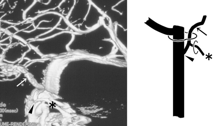
The IPS drains into the IJV at the level of the extracranial opening of the hypoglossal canal (Fig 3).
Fig 3.
3DRV rotation venogram (medial view of the right side) and schema (frontal view of the right side) of type B: The IPS (arrow) drains into the IJV (arrowhead) at the level of the extracranial opening of the hypoglossal canal and anastomoses with the VVP via the ACV (asterisk).
Type C.
The IPS drains into the lower extracranial IJV.
Subtype C-1.
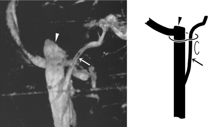
The IPS is a single route communicating to the IJV (Fig 4).
Fig 4.
3DRV (frontal view of the right side) and schema (frontal view of the right side) of type C-1: The IPS (arrow) shows a long extracranial extension and joins the IJV at the level of the atlas. In this case, the IPS has no anastomosis with the VVP. The arrowhead indicates the JB.
Subtype C-2.
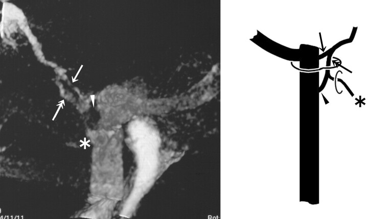
Another upper venous route exists (Fig 5).
Fig 5.
3DRV (anterolateral view of the right side) and schema (frontal view of the right side) of type C-2: The IPS (arrow) shows a long extracranial extension (double arrow). Note another upper junction (arrowhead) to the IJV and the anastomosis with the VVP via the ACV (asterisk) at the level of the extracranial opening of the hypoglossal canal.
Type D.
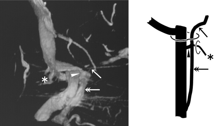
The IPS forms a plexus and has multiple junctions to the IJV around the jugular foramen (JF) (Fig 6).
Fig 6.
3DRV (medial view of the right side) and schema (frontal view of the right side) of type D: The upper route (arrow) that enters the JB has no anastomosis with the VVP, and the lower route (double arrows) anastomoses with the VVP via the ACV (asterisk) and enters the IJV (arrowhead).
Type E.
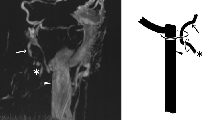
The IPS drains directly into the VVP with no connection to the IJV (Fig 7).
Fig 7.
3DRV (frontal view of the left side) and schema (frontal view of the right side) of type E: The IPS (arrow) has no connection to the IJV (arrowhead) and drains directly into the VVP via the ACV (asterisk).
Type F.
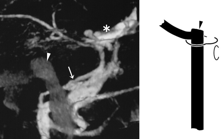
The IPS is absent (Fig 8).
Fig 8.
3DRV (medial view of the left side) and schema (frontal view of the right side) of type F: The IPS is absent, and the pterygoid plexus (arrow) shows marked development. An arrowhead indicates the JB; an asterisk indicates the cavernous sinus.
Prevalence and Characteristics of Each Type
The prevalence of each type is shown in Table 1. We evaluated the characteristics of each type on the level of the individual IPS-IJV junction and the pattern of the anastomosis with the VVP. The anastomosis with the VVP was found to be via the anterior condylar vein (ACV) or lateral condylar vein (LCV). The LCV commonly links the IJV to the VVP in the lateral region between the occipital bone and the atlas.7 The anastomosis with the VVP varied according to each anatomic type (Table 2).
Table 1:
The prevalence of each anatomic type
| Type | No. (%) |
|---|---|
| A | 1 (1.2) |
| B | 29 (34.9) |
| C | 31 (37.3) |
| D | 5 (6.0) |
| E | 3 (3.6) |
| F | 14 (16.9) |
Note:—N = 83.
Table 2:
Anastomosis of the IPS with the VVP in each anatomic type
| Characteristic | A | B | C-1 | C-2 | D | E | F |
|---|---|---|---|---|---|---|---|
| No. of sides | 1 | 29 | 23 | 8 | 5 | 3 | 14 |
| Pattern of anastomosis via | |||||||
| ACV (No., %) | 0 (0) | 21 (72.4) | 5 (21.7) | 8 (100) | 4 (80) | 3 (100) | 0 (0) |
| LCV (No., %) | 0 (0) | 4 (13.8) | 5 (21.7) | 1 (20) | 1 (20) | 0 (0) | 0 (0) |
| No anastomosis (No., %) | 1 (100) | 4 (13.8) | 13 (56.5) | 0 (0) | 0 (0) | 0 (0) | 14 (100) |
Note:—IPS indicates inferior petrosal sinus; VVP, vertebral venous plexus; ACV, anterior condylar vein; LCV, lateral condylar vein.
Type A was observed in only 1 side (1.2%), and the IPS had no apparent anastomosis with the VVP.
Type B was seen in 29 sides (34.9%). In most cases (21/29), the IPSs anastomosed with the VVP via the ACV and drained into the IJV approximately at the level of the ACV junction. Four sides had the anastomosis with the VVP via the LCV, and the other 4 sides had no anastomosis with the VVP.
Type C was noted in 31 sides (37.3%).
Type C-1 was found in 23 of the 31 sides. The level of low extracranial IPS termination varied. The junction to the IJV in most sides was at the level of the atlas (12 of the 23 junctions). IPS termination inferior to the atlas could not be assessed exactly with the level of the junction to the IJV because most images did not cover such aspects inferior to the atlas. In type C-1, the anastomosis with the VVP was not prevalent. Thirteen of the 23 sides of type C-1 had no anastomosis with VVP. The other 10 sides had anastomosis with the VVP via the ACV (5/23) or the LCV (5/23).
Type C-2 was observed in 8 of the 31 sides in type C. In all cases, the lower extracranial IPS termination was located inferior to the atlas, and the upper IPS-IJV junction was located at the level of the extracranial opening of the hypoglossal canal. In all 8 sides, the IPS had the anastomosis with VVP via the ACV near the upper IPS-IJV junction. In 1 of 8 sides, another anastomosis via the LCV was recognized.
Type D was detected in 5 sides (6.0%). Multiple routes from the IPS into the IJV tended to be of smaller calibers. The upper route entered the JB without any anastomosis to the VVP. The lower one entered the IJV at the level of the extracranial opening of the hypoglossal canal, forming anastomosis with the VVP via the ACV (4/5) or the LCV (1/5).
Type E was seen in 3 sides (3.6%). The IPS drained into the VVP directly via the ACV. Two of the 3 patients showed no connection with the IJV, and another had a connection via a very small venous channel with the IJV.
Type F was noted in 14 sides (16.9%). In all cases, venous drainage to the pterygoid venous plexus developed.
These characteristics of each anatomic type are also presented in Figs 2–8.
Discussion
Usefulness of 3DRV
Compared with the conventional 2D digital subtraction angiography (2D-DSA), 3DRV has enabled a more detailed assessment of the venous system surrounding the JF. 3DRV solves the difficulty involved with 2D-DSA, in which the IPS anatomy overlaps with the pterygoid venous plexus and the VVP in the front view and with the contralateral IJV in the lateral view.
Historical Review of the Anatomic Variation of the IPS-IJV Junction
Shiu et al3 presented the classification of variant IPS-JB junctions into the following 4 types:
Type I.
The IPS directly drains into the JB.
Type II.
The IPS drains into a communicating vein that links the JB to the deep cervical plexus.
Type III.
The IPS is poorly formed and exists as a plexus of veins. Through this plexus, the cavernous sinus drains posteriorly into the JB or a vein connecting the deep cervical plexus.
Type IV.
The IPS drains directly into the deep cervical plexus.
This classification was reviewed by Miller et al4,5 in the 1990s. They presented a modified classification system concentrating on the IPS-VVP anastomosis, but they did not describe the level of IPS-IJV junctions in detail. A variant of the low extracranial IPS-IJV junction has been reported sporadically by anatomists since the latter half of 1900s.8,9 Recently, Ayeni et al2 reported a variant of IPS-IJV junction at the level of the atlas in 1 side of 1 cadaver. Gailloud et al10 reported a bilateral extracranial extension of the IPS, joining the IJV at 40 mm below the skull base in 1 cadaver. They also found this variant in 4 of their 100 subjects in an angiographic assessment. Benndorf and Campi11 reported that they encountered 2 cases of a similar variant and performed transvenous embolization for the dural arteriovenous fistula of the cavernous sinus via the IPS connected to the low extracranial IJV. Another case of a similar variant was reported by Calzolari.12
The New Classification of the Drainage Patterns of the IPS
On a transvenous access to the cavernous sinus, the first hurdle is to search the IPS-IJV junction. We thus proposed a classification system with emphasis on the level of the IPS-IJV junction. In the present study, we found a high prevalence of type B, which seems to be a basic configuration, considering the embryogenesis of IPS evaluated by Padget,13 to whom we refer later. Type A was of a very low prevalence, and type C was noted at a much higher frequency than in previous reports. The difficulty of detailed assessment with 2D radiologic evaluation used in previous examinations may be a possible reason for this discrepancy. Type D and E corresponded to type III and IV, respectively, of the classifications of Shiu et al3 and Miller et al.4,5 The prevalence of type E was considerably low, being consistent with the reported of Miller et al. Type F anatomy was seen at a rather higher incidence than anticipated. Further investigation is required because the present assessment, performed with carotid artery imaging, did not include the presence of IPSs that provide venous drainage for the vertebrobasilar artery system.
Rationale of the New Classification from the Embryologic Viewpoint
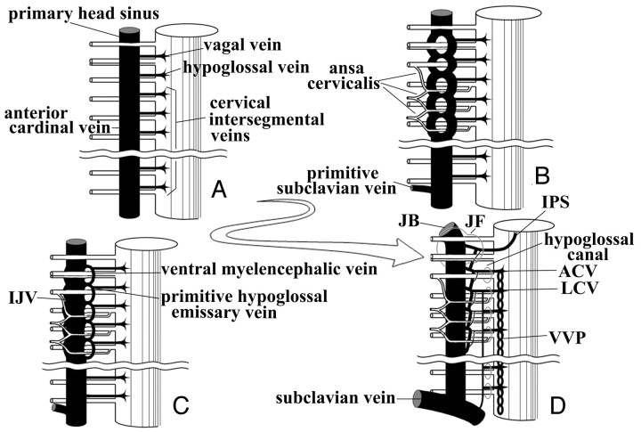
According to Padget,13 a pair of primary head sinuses is formed in the ventromedial side of the primitive brain at the early embryonic stage. The primary head sinus is directly continuous with the anterior cardinal vein (the future IJV). The primary head sinus and the anterior cardinal vein initially run ventromedially to the nerves situated caudal to the vagal nerve, and the pia-arachnoidal veins (vagal vein, hypoglossal vein, and so forth) drain directly into these venous structures. Then the primary head sinus and the anterior cardinal vein migrate dorsolaterally to the vagal, the accessory, and the hypoglossal nerves. During this development, the part of the primary head sinus and anterior cardinal vein that lies medial to the nerves does not degenerate and remains as the ventral myeloencephalic vein. The hypoglossal vein (future ACV) drains the ventral myeloencephalic vein that joins the IJV with its caudal end. The caudal portion of IPS is constituted with the ventral myeloencephalic vein.
On the basis of the previously presented information and the present results, we will discuss the development of venous structures around the JF. The hypoglossal nerve anastomoses with the 1st to 3rd cervical nerves, forming the ansa cervicalis. Because the ansa cervicalis usually runs ventromedially to the IJV, the anterior cardinal vein may migrate dorsolaterally not only to the hypoglossal nerve but also to the ansa cervicalis. When the migration of the primary head sinus and the anterior cardinal vein occurs dorsolaterally to nerves, the vagal vein, the hypoglossal vein, and the upper cervical intersegmental veins may anastomose with each other, resulting in a longitudinal venous channel to form the caudal portion of the IPS (Fig 9). The development or the degeneration of individual venous channels formed through the process may determine the anatomy of the caudal end of the IPS.
Fig 9.
Theoretic schematic representation of the development of the caudal portion of the IPS in the embryonic and fetal periods.
A, In the early embryonic phases, the primary head sinus and the anterior cardinal vein (the future IJV) run ventromedially to the vagal, accessory, and hypoglossal nerve and to cervical nerve roots.
B, The primary head sinus and the anterior cardinal vein migrate dorsolaterally to the lower cranial nerves and the ansa cervicalis, forming a venous plexus around nerves.
C, The vagal vein, the hypoglossal vein, and the upper cervical intersegmental veins are stretched and anastomose with each other on the ventromedial side of the IJV. The ventral myeloencephalic vein and the primitive hypoglossal emissary vein are formed through this process.
D, The ventral myeloencephalic vein is connected to the cavernous sinus with its cranial end, and the IPS is formed. The morphologic variation of the caudal portion of the IPS may be determined by the extent of development and degeneration of individual venous channels.
The characteristics of each variation of our classification can be explained rationally with the theory noted previously (Fig 10). In type A, the caudal end of the IPS is formed only by the vagal vein, so the anastomosis of the IPS with the VVP may be absent. In type B, the anastomosis of the vagal vein and the hypoglossal vein constitutes the caudal end of the IPS. Therefore, the anastomosis with the VVP via the ACV is common. In type C-1, the longitudinal anastomosis of the vagal vein, the hypoglossal vein, and the upper cervical intersegmental veins constitutes the caudal end of the IPS. In type C-2, the upper IPS-IJV junction is formed in the same manner as in type B. In type D, the upper and the lower route of the IPS is formed as in type A and in type B, respectively. Type E anatomy includes the developed anastomosis of the vagal vein and the hypoglossal vein with the degenerated IPS-IJV junction, so the IPS seems to be connected to the VVP directly. In type F, the IPS has never been formed or has been occluded by an acquired cause.
Fig 10.
The new classification is evaluated with our theory about the development of the caudal portion of the IPS.
In type A, the caudal portion of the IPS is derived from the vagal vein only and has no anastomosis with the VVP.
In type B, the caudal portion of the IPS is formed by the anastomosis of the vagal vein and the hypoglossal vein, so the anastomosis with the VVP via the ACV is common.
In type C-1, the caudal portion of the IPS is formed by the longitudinal anastomosis of the vagal vein, the hypoglossal vein, and the cervical intersegmental veins and drains into the extracranial lower IJV.
In type C-2, the upper venous route is formed as in type B, and the another lower route develops as in type C-1.
In type D, the development of the upper route drains is the same as that in type A, and the lower route develops as in type B.
In type E, no venous channel connecting the IPS to the IJV develops, and the venous return drains directly into the VVP via the venous route formed by anastomosis between the vagal vein and the hypoglossal vein.
In type F, the IPS is absent.
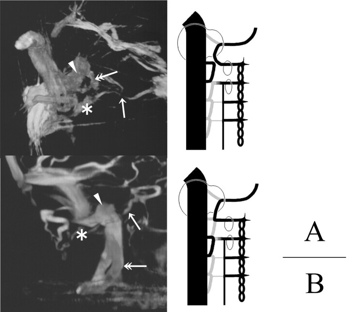
Two cases of type E are presented in Fig 11. In these cases, we recognize the duplicated channel of the IJV. It is speculated that the duplicated channels might be formed with the anastomosis between the hypoglossal vein and the 1st cervical intersegmental vein in the case presented in Fig. 11A and between the 1st and 2nd cervical intersegmental vein in the case of Fig. 11B. This observation appears to support our theory.
Fig 11.
3DRVs (A, superomedial view of the left side; B, medial view of the left side) and schemas presenting our theory of the development of the caudal end of the IPS (ventral view of the right side) are shown. In these cases, we can find a duplicated venous channel (double arrow) with the IJV. The arrow indicates the IPS, the arrowhead indicates the JB, and the asterisk indicates the ACV.
A, The duplicated channel may be formed with the longitudinal anastomosis of the hypoglossal vein and the 1st cervical intersegmental vein.
B, The duplicated channel may be formed with the longitudinal anastomosis of the 1st and 2nd cervical intersegmental veins.
Conclusions
In the present study, drainage patterns of the IPS were classified on an anatomic basis by using 3DRV, which is a useful tool for interpretation of 3D venous structures around the JF. Our classification and the theory of the development of the caudal end of the IPS may be useful in establishing treatment strategies that involve endovascular manipulation via the IPS.
Footnotes
Paper previously presented at: 8th Congress of the World Federation of Interventional and Therapeutic Neuroradiology, October 19–23, 2005; Venice, Lido, Italy.
References
- 1.Katsuta T, Rhoton AL Jr, Matsushima T. The jugular foramen: microsurgical anatomy and operative approaches. Neurosurgery 1997;41:149–202 [DOI] [PubMed] [Google Scholar]
- 2.Ayeni SA, Ohata K, Tanaka K, et al. The microsurgical anatomy of the jugular foramen. J Neurosurg 1995;83:903–09 [DOI] [PubMed] [Google Scholar]
- 3.Shiu PC, Hanafee WN, Wilson GH, et al. Cavernous sinus venography. Am J Roentgenol Radium Ther Nucl Med 1968;104:57–62 [DOI] [PubMed] [Google Scholar]
- 4.Miller DL, Doppmann JL. Petrosal sinus sampling: technique and rationale (comments). Radiology 1991;178:37–47 [DOI] [PubMed] [Google Scholar]
- 5.Miller DL, Doppman JL, Chang R. Anatomy of the junction of the inferior petrosal sinus and the internal jugular vein. AJNR Am J Neuroradiol 1993;14:1075–83 [PMC free article] [PubMed] [Google Scholar]
- 6.Nishio A, Takami T, Ohata K, et al. Three-dimensional rotation venography using the digital subtraction angiography unit with a flat-panel detector: usefulness for the transtemporal/transtentorial approaches. Neuroradiology 2004;46:876–82 [DOI] [PubMed] [Google Scholar]
- 7.Arnautovic KI, Al-Mefty O, Pait TG, et al. The suboccipital cavernous sinus. J Neurosurg 1997;86:252–62 [DOI] [PubMed] [Google Scholar]
- 8.Charpy A, Hovelacque A. Traite d'anatomie humaine de Poirier et Charpy. In: Nicolas A, ed. Veines. Tome 2, Fasc 3, 3rd ed. Paris, France: Masson;1920. :53–278
- 9.Knott JF. On the cerebral sinuses and their variation. Journal of Anatomical Physiology 1882;16:27–34 [PMC free article] [PubMed] [Google Scholar]
- 10.Gailloud P, Fasel JH, Muster M, et al. Termination of the inferior petrosal sinus: an anatomical variant. Clin Anat 1997;10:92–96 [DOI] [PubMed] [Google Scholar]
- 11.Benndorf G, Campi A. Aberrant inferior petrosal sinus: unusual transvenous approach to the cavernous sinus. Neuroradiology 2002;44:158–63 [DOI] [PubMed] [Google Scholar]
- 12.Calzolari F. Unusual termination of the inferior petrosal sinus. Neuroradiology 2002;44:796–97 [DOI] [PubMed] [Google Scholar]
- 13.Padget DH. The development of the cranial venous system in man, from the view point of comparative anatomy. Contrib Embryol 1957;36:81–140 [Google Scholar]


