

Abstract
The availability of 3D printers and a variety of polymers that can be fashioned into a wide variety of shapes provides opportunities to rethink the design and construction of probes for NMR spectroscopy. The direct interfacing of computer aided design (CAD) with precise 3D printing enables the simplification and optimization of probes through the rapid production of components. Here we demonstrate the use of 3D printing to fully integrate a permanent former for the radiofrequency (RF) coil with the sample chamber (equivalent to the sample tube). This simultaneously increases the sample volume and improves the filling factor within a fixed outer diameter (OD). It also reduces the space lost in dual coil arrangements where a high frequency resonator is positioned outside a solenoid coil tuned to one or more lower frequencies, making multiple-resonance experiments more efficient. The initial applications demonstrate opportunities for future designs that reimagine the interface between resonators and the liquid, solid, and heterogeneous samples encountered in NMR studies of biomolecules, polymers, surfaces, and spectroscopy (MRS) and imaging (MRI) of biological organs and intact organisms.
Introduction
The probe is one of the most important components of a nuclear magnetic resonance (NMR) spectrometer, since it provides the interface between the sample and the radiofrequency (RF) circuitry responsible for both exciting and detecting the nuclei of interest. As a result, improvements to the probe have disproportionate influences on the quality of experimental NMR data. 3D printing, also known as additive manufacturing, has been in use since the 1980s, originally as a method for the rapid prototyping of parts intended to be manufactured in bulk [1]. 3D printing has been applied in many endeavors including artwork, medical appliances, and scientific instruments. The close interface with computer aided design (CAD) facilitates this process because individual parts can be evaluated visually on the computer’s graphic display and, more importantly, directly as fabricated three-dimensional solid objects. These objects, which can be quite complex by incorporating empty volumes, tubes, and intricate internal and external configurations, might be difficult or impossible to produce by conventional machining techniques. In addition, all the values input to the CAD program as well as measurements of the resulting objects can be performed using arbitrary units. This avoids the delays and errors often introduced by conversions from precise metric designs output from CAD programs the approximate fractions of inches typically used by machinists.
3D printing has been previously applied to the instrumentation for NMR spectroscopy, primarily for the fabrication of parts used in the construction of one-off home-built probes. This includes insulating and structural components, stators and rotor caps used in magic angle spinning (MAS), and removable temporary formers that enable precise positioning of the wire in solenoid coils and other types of resonators [2–6]. Here we explore the use of 3D printing in the design and construction of integrated sample chambers and permanent coil formers that improve the filling factor, a key parameter in the performance of a probe, as well as the positioning the coil so that it is as close as possible to the sample, which improves the effectiveness of the RF irradiations in generating the magnetic fields used to manipulate the nuclear spins, and by reciprocity improves detection of the responses to the RF pulses, which provides greater sensitivity. These designs also serve to eliminate the need for the intervening layers of glass, vacuum, and glass reinforced plastic (GRP) typically required to maintain the sample temperature and enable the exchange of replaceable sample tubes. This approach has the potential to not only optimize the filling factor but also the homogeneity of RF fields across the entire sample volume. The mechanical support provided by the integrated coil former enables wire to be placed in precise patterns for variable pitch solenoid coils, Helmholtz coils, and the use of very thin and flexible wire, which is especially useful for small diameter coils.
The starting materials used in the production of 3D printed components determine many properties of the final products, including intrinsic strength and structural integrity, opportunities for preparing sample chambers with the thinnest possible walls, and minimizing water permeability. Many polymers are readily available for use in 3D printers. Here we use four different polymers: glycol-modified polyethylene terephthalate (PTEG), high impact polystyrene (HIPS), polylactic acid (PLA) and Nylon, all of which are available commercially at relatively low cost. All four were used successfully to print prototypes of thin wall sample tubes capable of supporting solenoid coils. Selected properties of the four polymers are compared in Table 1 [7–9].
Table 1.
Properties of polymers used for 3D printing of probe components
| Materials | Tensile Strength | Hygroscopic | Printability |
|---|---|---|---|
| PETG | MEDIUM | YES | HIGH |
| HIPS | LOW | NO | MEDIUM |
| PLA | HIGH | YES | HIGH |
| Nylon | MEDIUM-HIGH | YES | HIGH |
Materials and Methods
Three-dimensional spatial models of integrated RF coil formers and sample chambers were designed using the program Autodesk Tinkercad (www.tinkercad.com). This program provides the flexibility needed to design parts that could be used with a wide variety of coil and sample chamber geometries and sizes. Its ease of use facilitated the optimization of dimensions and orientations through incremental design changes that could be evaluated both visually on the computer screen as well as physically in the printed prototypes.
A LulzBot Mini2 3D printer (www.lulzbot.com) equipped with a 0.1 mm copper nozzle with MK8 thread was used with 1.75 mm filaments to make thin-wall cylindrical sample chambers. The glycol-modified polyethylene terephthalate (PTEG) filaments were obtained from Overture (www.overture3d.com), the high impact polystyrene (HIPS) and Nylon filaments were obtained from Gizmo Dorks (www.gizmodorks.com), and the polylactic acid (PLA) filaments were obtained from Kodak (www.kodak.com). Because of the hygroscopic nature of these materials, a thin layer of silicone glue (RTV118) was applied to the inner surfaces of the printed chambers to inhibit absorption of water and proteins; excess glue was carefully removed with a cotton swab before drying. Measured weights of water were used to determine the net volumes and to test for leakage.
Two home-built solid-state NMR probes were used in these studies. The unbalanced single solenoid coil probe shown in Figure 1A was constructed for use with crystalline samples using the circuit diagram in Figure 1C. The dual-coil modified Alderman-Grant coil (MAGC) probe (Figure 1B) was constructed for use with electrically lossy liquid samples using the circuit diagrams in Figure 1D. For the most part, the design, components, assembly, and tuning of both types of probes followed the approaches that we have previously described [10–12]. The major differences were in the incorporation of 3D printed components as sample chambers and supports for the wire coils. The solenoid coils were wound with 0.4 mm x 1.0 mm oxygen-free copper wire (www.mwswire.com). The capacitance values of the chip capacitors (www.atceramics.com) are listed in Table 2A and the properties of the inductors are listed in Table 2B.
Figure 1.
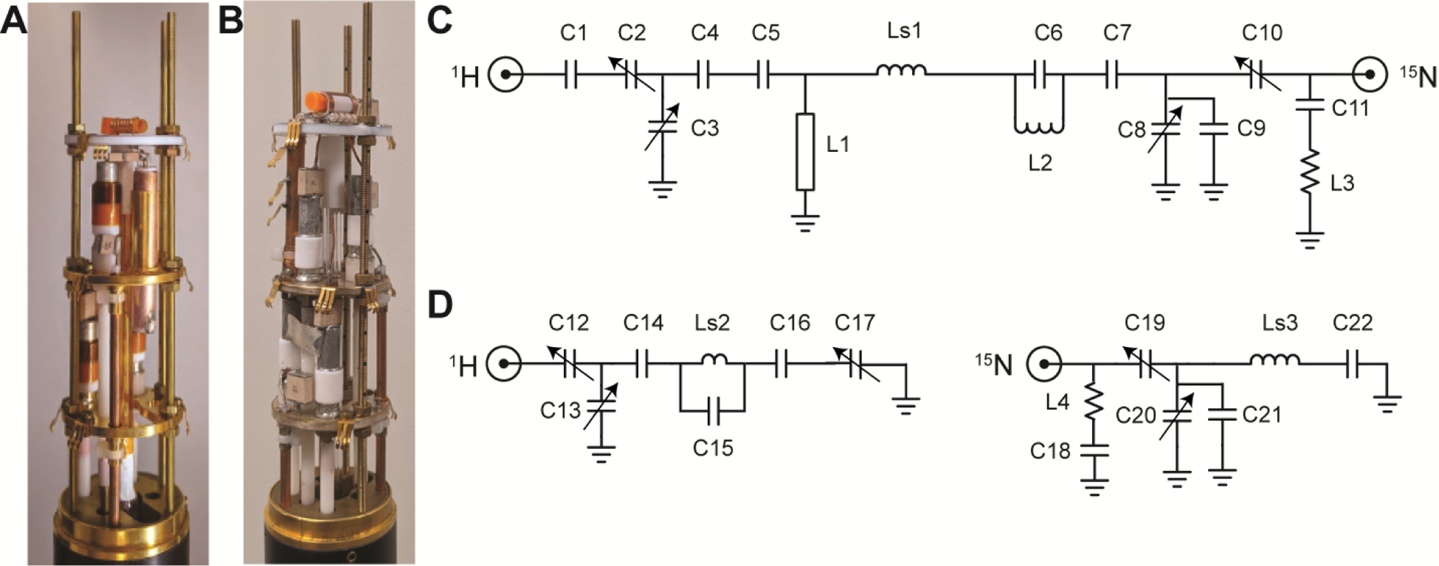
A. 1H-15N double-tuned single solenoid coil probe with a 3D printed integrated cylindrical sample chamber/coil support. B. 1H-15N dual-coil probe with a MAGC resonator on the outside of a solenoid coil wrapped on a 3D printed integrated cylindrical sample chamber/coil support. C. 1H-15N double-tuned circuit diagram for the solenoid single-coil probe in A. D. Circuit diagrams for the two channels of the dual coil probe in B. Inductors and capacitors used in the circuit diagrams in C. and D. Ls1, Ls2 and Ls3 are sample coils. Ls1 and Ls3 are solenoid coils and Ls2 is a MAGC resonator. C2, C3, C8, C10, C12, C13, C17, C19, and C20 are variable capacitors. C15 is composed of four parallel rows of chip capacitors. Each row is composed of four 1.5 pF chip capacitors connected in series.
Table 2.
Values of the capacitors and inductors
| solenoid probe | |
|---|---|
| Capacitor | Capacitance |
| C1 | 3.9 pF |
| C4 | 1.2 pF |
| C5 | 1.2 pF |
| C6 | 8.2 pF |
| C7 | 56 pF |
| C7* | 33 pF |
| C9 | 39 pF |
| C9* | 33 pF |
| C11 | 5.6 pF |
| MAGC probe | |
| Capacitor | Capacitance |
| C14 | 1.2 pF |
| C15 | 1.5 pF |
| C16 | 2.2 pF |
| C18 | 6.8 pF |
| C21 | 68 pF |
| C22 | 68 pF |
| solenoid probe | |
| L1 | 57 mm length 8 mm diameter transmission line |
| L1* | 55 mm length 8 mm diameter transmission line |
| Ls1 | 7 turns solenoid sample coil |
| L2 | ½ turn inductor |
| L3 | ½ turn inductor |
| MAGC probe | |
| Ls2 | MAGC sample coil |
| L4 | ¼ turn inductor |
| Ls3 | 7 turns solenoid sample coil |
Indicates values used in the “flat” coil probe.
The power levels of the RF irradiations were adjusted to generate 50 kHz fields on both the 1H and 15N channels of the double-tuned single solenoid coil probe. For experiments performed with the dual-coil MAGC probe the RF irradiations were adjusted to generate 43 kHz fields on both the 1H tuned resonator and the 15N tuned solenoid coil. In the experiments performed with both probes, the same 1H field strengths were used for cw matched cross-polarization and heteronuclear decoupling during data acquisition. Cross-polarization contact times were typically 1 msec. High resolution separated local field (SAMPI4) experiments were performed as previously described [13]. In all experiments SPINAL decoupling was applied during data acquisition [14]. All of the NMR experiments were performed in a magnetic field corresponding to a 1H resonance frequency of 700 MHz. The spectra obtained from the single- and poly- crystalline samples were acquired at ambient temperature, and the spectra of the protein-containing bilayer disc (bicelle) samples were acquired at 40°C. 15N chemical shifts were referenced to the signal from external 15N labelled ammonium sulfate at 26.8 ppm. Data processing was performed using the program Topspin 4 (www.bruker.com).
15N labeled proline was obtained from Cambridge Isotope Laboratories (www.isotope.com). The single crystal of 15N labeled N-acetyl leucine (NAL) was prepared as previously described [11]. Uniformly 15N labelled Pf1 bacteriophage was also prepared as previously described [15]. The protein-containing phospholipid bilayers were prepared as previously described with 1,2-dimyristoyl-sn-glycero-3-phosphocholine (DMPC) (www.anatrace.com) as the “long chain” lipid and Triton X-100 (www.sigmaaldrich.com) as the “short chain” lipid [16, 17] to form magnetically alignable bicelles [18, 19]. At relatively low temperatures the protein-containing bicelle samples are fluid and can be pipetted into conventional glass sample tubes or the coated thin-wall 3D printed polymer tubes.
Results and Discussion
Commercial 3D printers intended for the consumer market, such as the LulzBot Mini2, are generally designed to print objects with a 0.25 mm minimum wall thickness. NMR experiments benefit from the use of sample tubes with the thinnest walls. The print resolution is limited by the configuration of the nozzle heads when using fused deposition modeling (FDM) methods [20]. However, by using smaller extrusion heads with the corresponding instrument settings, cylinders (and other shapes) with very thin walls can be printed, which is crucial for the design and construction of sample chambers that provide optimal filling factors. By using 0.1 mm nozzle heads, wall thicknesses of 0.15 mm were achieved with the LulzBot Mini2 3D printer. Alternative printing methodologies such as stereolithography or selective laser sintering [21–23] are capable of providing products with even thinner walls. Still there are many advantages to the widely used FDM methods. For example, the printed products do not require curing, thus optimization through the rapid testing of new designs is more convenient. Another benefit of FDM is that it enables printing with a wider variety of polymeric materials yielding components with a range of properties that are optimal for different resonators, probes and experiments.
Figure 2 contains three-dimensional images of thin-wall cylindrical sample chambers that constrain the positions of the wire wrapped on the outside, but still in close proximity to the samples. The integrated cylindrical tubes and coil supports shown in Figure 2A and 2B are the result of many design iterations examined and tested as printed prototypes. The sample chamber in Figure 2A is designed for use with a single solenoid coil, which can be tuned and matched for one or several frequencies using established electrical circuits. In all cases the performance is improved by the placement of the smallest possible diameter RF coil in closest possible proximity to the sample. For a given power level, the RF field strength generated is stronger, and the signal intensity is larger due to the reciprocal nature of single coil circuits. A double-tuned version was implemented in the probe used to obtain the experimental solid-state NMR results for single- and poly- crystalline samples. The “bottom” end of the sample chamber is anchored by a solid hexahedron that provides mechanical support for the weak thin walls during wire wrapping and the packing of powders; it also provides a grip for holding and manipulating a fragile tube with thin wire wrapped on the outside and a valuable sample on the inside.
Figure 2.
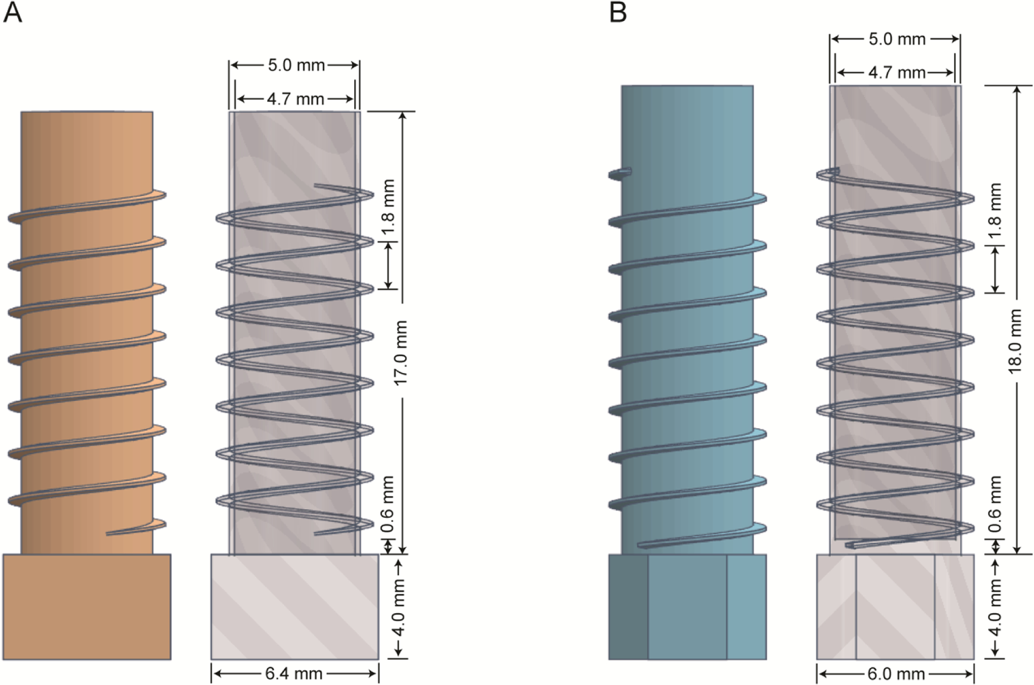
Solid and transparent illustrations with marked dimensions of the 3D printed components that integrate the functions of a sample tube and coil support. A. Design optimized for solid materials and a single solenoid coil. B. Design optimized for biopolymers in aqueous environments and located as the inner solenoid coil with an outer MAGC resonator.
Samples of biomolecules in near-native aqueous environments typically have high ionic strengths that makes them electrically lossy. This results in drastic shifts of tuning frequencies and reductions of quality factors (Q) of high frequency circuits. A number of probe designs have been developed to deal with this problem [10, 24, 25]. Here we utilize a dual-coil configuration where each coil is tuned and matched for a specific frequency in a single-coil circuit. The lower frequency inner solenoid coil is optimized for direct detection of the “dilute” nucleus as defined by having a relatively low gyromagnetic ratio and no or weak couplings among like nuclei; here 15N in labeled sites that are spatially separated. The high frequency resonator tuned to the 1H resonance frequency is a modified Alderman-Grant coil (MAGC) that surrounds the inner coil illustrated in Figure 2B. Starting with the design in Figure 2A, the tubular sample chamber shown in Figure 2B is optimized to closely fit within the outer MAGC. In addition, the location of the liquid sample volume is arranged to match the homogeneous regions of the coils. As mentioned above, the space between the bottom of the tube and the bottom of the first wire positioning groove is printed as a solid; an added benefit is that this provides another adjustable parameter for centering the sample volume in the most homogeneous region of the coils. In addition, the empty space on top of the sample chamber is elongated in order to facilitate the placement of a rubber cap that seals the sample. The close fit of the rubber cap is particularly critical for liquid samples to avoid losses due to evaporation, especially since many experiments on magnetically aligned protein samples are performed at elevated temperatures, 35°C – 65°C. We took advantage of the ability to rapidly print multiple prototypes with slight variations of inner dimensions in order to obtain an air-tight seal without distorting the sample chamber or wire positions. The dimensions can be adjusted to accommodate individual plugs and to take into account any expansion or contraction of the materials at different temperatures. Custom pressed-fit or screw-on caps can be designed and printed to seal any particular sample chamber. Loss of volume due to evaporation is monitored by weighing the sample before and after each experiment. We were able to produce seals with rubber caps that prevented significant evaporation over the course of several days at 40oC.
The distinctive fins on the outside of the sample-containing tube are a major feature of the design used with solenoid coils. By providing external support, they enable a maximum inner diameter to enhance sample volume, optimal length for location of the sample in the “sweet spot” of the RF coils and a minimum wall thickness for optimal filling factor. The fins guide and secure the placement of the thin flat wire used for minimal electrical resistance in an externally wound solenoid coil. The support is essential to deal with the inherent flexibility of very thin copper wire. The fins also serve as insulating barriers to prevent arcing between turns of the tightly spaced wire. Since the integrated coil support / sample chamber is designed using a computer program and printed with a high-resolution 3D printer, the pitch and thickness of the fins allows for variable spacing of the wire throughout the length of the tube in order to optimize the RF field homogeneity [3, 26]. Only by placing the wire directly on the outside of the thinnest printable tube can the gains of this approach be fully realized.
As shown in Figure 3, the choice of polymer used in the printing affects the quality of the fins. The optimal fin quality for each polymer was determined empirically by adjusting various settings on the printer. We found that HIPS yields the best quality fins, PETG gives fins with a somewhat coarser finish that require final trimming with a scalpel, and PLA results in the thickest fins. It appears that deformation of the fins results from the effects of gravity during liquid polymer layering without bottom support. This suggests that quality could be improved by 3D printing in the zero-gravity environment of the International Space Station.
Figure 3.

A. Finned sample chambers used for the poly- and single- crystalline samples in the double-tuned single coil probe (Figure 1A) are shown on the left; finned sample chambers for aqueous samples in the dual-coil MAGC probe (Figure 1B) are shown on the right. B. 5X magnified images corresponding to the positions of the white arrows in Panel A. illustrate the quality of the printed surface and fins.
Although printing with HIPS yields well finished and consistent parts, they tend to be fragile and easily broken, causing obstruction in the printer extruder. Therefore, we rate them medium in the “difficult to print thin wall” category in Table 6. PETG is difficult to work with in this application; the tubes contain many defects and the print conditions require significant optimization. PLA is easier to work with and the defect rate is low, however, the finish quality and durability are poor. Compared to the other three materials, Nylon yields higher quality with greater durability and its printing is easier to optimize. However, because it is highly hydroscopic, it is counter-indicated for use with aqueous samples. Taking into account all factors, we generally use finned sample tubes printed with PETG for NMR experiments. The positioning of several types of printed sample chambers within the coils and resonators of tuned RF circuits is illustrated in Figure 4.
Figure 4.

Photographs of printed PETG sample chambers / coil supports in various states of assembly. A. 5 mm OD finned cylindrical sample chamber with a double-tuned single solenoid coil wrapped on the outside. B. 5 mm OD finned cylindrical sample chamber placed inside a MAGC in a dual-coil probe for biopolymers in aqueous solution. C. NAL single crystal placed in a printed “flat-coil” sample chamber 8 mm (L) x 6 mm (W) x 2 mm (H). D. Finned sample chamber shown in Panel C. wrapped with 32-gauge copper wire and mounted parallel to the ground plane of a single coil probe.
Since these materials are organic polymers, they have the potential to contribute natural abundance background signals to 1H and 13C NMR spectra. Nylon consists of polyamides, whose N-H bonds are similar to those in the amide groups of protein backbones and whose signals have the potential to weakly interfere with those from the sample. While problematic for most 13C NMR experiments, the polymers are well-suited for 15N NMR experiments on labeled compounds. They can also be used for the detection of 19F and 31P signals from sites in biomolecules, as well as many other MR active” nuclei.
Typical experimental 1H decoupled 15N NMR spectra of labeled amino acids, peptides, and proteins obtained with 3D printed double-resonance probes are presented in Figures 5, 6, and 7. Figure 5 contains one- and two- dimensional 15N NMR spectra of crystalline samples. Figure 5C is a spectrum of polycrystalline powder sample of 15N labeled proline. The sensitivity is improved as a result of more material packed in the thin-wall tube with its larger volume and the improved filling factor that is a consequence of the coil being wrapped directly on the outside of the tube, separated from the sample by only 0.15 mm. This also benefits heteronuclear decoupling by improving the efficiency of the RF irradiation. Effective RF decoupling is apparent in the one-dimensional 15N NMR spectrum in Figure 5C where all three discontinuities of the axially asymmetric chemical shift powder pattern can be readily discerned even though the span of the 15N chemical shift tensor of an imino nitrogen is only ~70 PPM and in the spectrum of a single-crystal of the model peptide N-acetyl-leucine (NAL) in Figure 5A where narrow single-line resonances are observed even though the span of the 15N chemical shift tensor of am amide nitrogen is ~170 ppm. In both compounds the nitrogen is strongly coupled to a directly bonded hydrogen. Although each NAL molecule contains a single 15N labeled site, four narrow resonances result from the symmetry characteristics of the unit cell [11]. To optimize the filling factor for the crystal sample an 8 mm (length) x 6 mm (width) x 2 mm (thick) PETG sample chamber was made, demonstrating the design flexibility of the 3D printing method. The smaller profile tube fits into a much smaller coil, which improves RF efficiency. A photograph of the tube and the single crystal is shown in Figure 4C and the tube mounted in the probe is in Figure 4D. The sensitivity of the spectrum in Figure 5B is much improved compared to that of the same crystal sample placed in a larger coil in Figure 5A. A two-dimensional NMR spectrum of the crystal at the same orientation is shown in Figure 5D.
Figure 5.

A. 15N NMR spectrum of a 15N-labeled NAL single crystal in the single coil probe shown in Figure 1A: acquired with 32 transients, 20 ms acquisition time, and 10 sec recycle delay. B. Same as A except in the “flat-coil” probe shown in Figure 4D. C. 15N NMR spectrum of 15N-labeled proline powder in the single coil probe shown in Figure 1A, acquired with 64 transients, 4 msec acquisition time, and 10 sec recycle delay. D. High-resolution two-dimensional separated local field spectrum obtained with the SAMPI4 pulse sequence on the same sample and probe as in Panel B: 64 t1 points acquired with 2 transients, 20 msec acquisition time and processed with sine squared bell functions.
Figure 6.

15N NMR spectra of uniformly 15N labeled membrane-bound coat protein of Pf1 bacteriophage in magnetically aligned q=5.0 DMPC/Triton X-100 bicelles. The bilayer normal is perpendicular to the direction of the magnetic field. The spectra were obtained with double-ramped adiabatic cross-polarization. A. 200 μL sample in a 5 mm OD 3D printed chamber. C. Expanded section of A. between the two arrowheads. B. Same as C., except that 150 μL of the same sample is contained in a 5 mm OD glass sample tube inserted in the solenoid coil of the dual-coil probe. The expanded spectral regions shown in B. and C are from spectra resulting the co-addition of 4,000 free induction decays and processed using identical squared sine bell functions. The protein concentration in both samples is 1.43 mg/mL.
Figure 7.

High-resolution two-dimensional separated local field spectrum obtained with the SAMPI4 pulse sequence on the same sample of Pf1 coat protein in magnetically aligned bicelles used in Figure 6. 64 t1 points acquired with 512 transients and processed with sine squared bell functions.
Our primary interest is in improving the performance of NMR spectrometers for studies of biomolecules. For soluble proteins, the samples are aqueous solutions while for membrane proteins the samples have high concentrations of phospholipids. Both types of samples typically contain buffers and salts which contribute to their high ionic strength and lossy electrical characteristics. At high frequencies, lossy samples degrade the performance of conventional RF coils, such as the double-tuned solenoid (Figure 1A) used to obtain data (Figure 5) from non-lossy crystalline solids. The critical tests of new instrumentation developments are performed on lossy biological samples. Representative results are shown in Figures 6 and 7 with one- and two- dimensional spectra obtained on a sample of uniformly 15N labeled membrane-bound form of Pf1 coat protein in phospholipid bilayers where the addition of a “short-chain lipid”, in this case the detergent Triton X-100, forms magnetically alignable bicelles (bilayer discs) [17]. At high q values (q is the molar ratio of the long-chain lipid to the short-chain lipid), here q=5, and at the appropriate temperatures, here 40°C, the protein is immobilized on the critical NMR timescales and is aligned by the magnetic field. These are the requirements for structure determination by oriented sample (OS) solid-state NMR. These samples have the drawback of being extremely lossy at high frequencies, thus a dual coil arrangement is implemented where a resonator that is minimally affected by the lossy sample is tuned for the high 1H resonance frequency, and the low frequency 15N channel can use a conventional solenoid coil.
A 1H/15N double-resonance probe with a dual-coil configuration is shown in Figure 1B; the circuits for the 1H and 15N channels are shown in Figure 1D with the details in the figure legend and Table 2A and 2B. The outer resonator is a modified Alderman-Grant coil tuned to the 1H resonance frequency of 700 MHz. The inner solenoid coil is tuned to the 15N resonance frequency of 71 MHz. The performance of the probe with a 3D printed PETG sample chamber (Figure 6A) containing an aligned protein sample is compared to that with the same sample in a conventional 5 mm outer diameter (OD) glass NMR sample tube (Figure 6B). The spectra were obtained under the same experimental conditions including signal averaging with the co-addition of 4,000 free induction decays. With the same noise levels, the signals in Figure 6B are measurably larger than those in Figure 6A, indicating an improvement of the signal-to-noise ratio. This improvement is results from several factors. Due to the flexibility in the design of the 3D printed tube, the sample volume was 200 μL compared to 150 μL in the conventional glass tube. This increase in volume is due to both the thinner walls (0.15 mm) of the 3D printed sample chamber compared to those of the glass tube (0.45 mm), as well as the greater length occupied by the sample in the printed tube.
A two-dimensional high-resolution separated local field [27, 28] spectrum of the aligned bicelle sample obtained with the SAMPI4 pulse sequence is shown in Figure 7. The spectrum rivals the best we have previously published [11, 15, 17] clearly demonstrating that the 3D printed probes can be used to obtain high quality spectra of aligned samples.
Here each sample is loaded into its own custom-printed sample chamber and integrated coil. Changing samples requires unsoldering the old sample and then soldering the leads for the new sample. The printed and wire components can be produced at low cost and with high reproducibility, and any changes in probe tuning are well within the range of the adjustable capacitors. These are all advantages of this approach; however, we have anecdotal evidence that the plastic materials might affect the alignment properties of the bicelles, resulting in slightly broader 31P linewidths of the phospholipids and 1H/15N resolution of the proteins. These effects are subject to future investigations.
Conclusions
Here we demonstrate several advantages of integrating 3D printing into the design and construction of NMR probes, including complete flexibility in the choice of sample volumes, improved filling factors due to the production of very thin wall sample chambers, and the resulting close proximity of the RF coil to the sample. The wire that forms a solenoidal coil or resonator is wrapped on the surface of the sample chamber or threaded through its walls. This approach lends itself to multi-coil arrangements with close packing of the resonators, and it opens up possibilities for entirely new resonator configurations.
This initial demonstration of using components produced through 3D printing technology in NMR probes is focused on the simplest example, the cylindrical sample chamber, where the sample volume can be increased within the same outer diameter, typically a limiting factor in probe design, by printing chambers with very thin walls. Substantial gains in filling factor over conventional probe designs result from the elimination of multiple layers of tubing and vacuum and the spacing needed to protect sensitive components, to regulate sample temperature, and allow for ease of changing samples. With the use of the sample chamber itself as the support for the RF coil, there is no need for the use of separate interchangeable sample tubes. The actual sample can be changed in one of two ways: if a removable cap is integrated into one end of the sample chamber, then when the probe is removed from the magnet the sample can be pipetted out instead it can be tipped over and the sample poured out; the chamber can then be cleaned and dried before loading another sample. Alternatively, the sample can remain undisturbed within the intact chamber and coil assembly for storage, requiring unsoldering the leads and then soldering in an entire new sample-containing assembly. The latter is feasible because of the extremely low cost of the polymer and wire materials. And the intact sample-containing assembly can be stored in a refrigerator or freezer between experiments.
Further advances lie in the printing of integrated coil formers / sample chambers with a range of sizes and shapes. A wide variety of resonators can be accommodated precisely alone or in combinations on the outside or embedded within the walls of the sample tube. If you can imagine it, you can print it.
Table 3.
Materials affect the quality of printed components
| Materials | Finish Quality | Durability | Difficult to Print Thin Wall | Defect Rate |
|---|---|---|---|---|
| PETG | Medium | High | High | High |
| HIPS | High | Medium | Medium | Low |
| PLA | Low | Low | Low | Low |
| Nylon | High | High | Low | Low |
Highlights.
NMR sample tubes can be designed and produced by combing CAD with 3D printing.
Integration of the sample chamber with the coil support places the wire of the resonator as close as possible to the actual sample improving the filling factor and overall efficiency.
This proof of concept opens the path to entirely new probe designs that can be rapidly prototyped and inexpensively produced with 3D printing.
Acknowledgements
We thank Professor Rachel Martin and Dr. Sang Ho Park for helpful discussions on 3D printed components, and Dr. Park for assistance with sample preparation. This research was supported by grants P41EB002031 and R35GM122501 from the National Institutes of Health and utilized the Biomedical Technology Resource Center for NMR Molecular Imaging of Proteins at the University of California, San Diego.
Footnotes
Publisher's Disclaimer: This is a PDF file of an unedited manuscript that has been accepted for publication. As a service to our customers we are providing this early version of the manuscript. The manuscript will undergo copyediting, typesetting, and review of the resulting proof before it is published in its final form. Please note that during the production process errors may be discovered which could affect the content, and all legal disclaimers that apply to the journal pertain.
References
- 1.Ligon SC, et al. , Polymers for 3D Printing and Customized Additive Manufacturing. Chemical Reviews, 2017. 117(15): p. 10212–10290. [DOI] [PMC free article] [PubMed] [Google Scholar]
- 2.Chen P, et al. , Magic angle spinning spheres. Sci Adv, 2018. 4(9): p. eaau1540.. [DOI] [PMC free article] [PubMed] [Google Scholar]
- 3.Kelz JI, Kelly JE, and Martin RW, 3D-printed dissolvable inserts for efficient and customizable fabrication of NMR transceiver coils. J Magn Reson, 2019. 305: p. 89–92. [DOI] [PMC free article] [PubMed] [Google Scholar]
- 4.Lederle F, et al. , Sonogashira coupling in 3D-printed NMR cuvettes: synthesis and properties of arylnaphthylalkynes. New Journal of Chemistry, 2017. 41(5): p. 1925–1932. [Google Scholar]
- 5.Montinaro E, et al. , 3D printed microchannels for sub-nL NMR spectroscopy. Plos One, 2018. 13(5). [DOI] [PMC free article] [PubMed] [Google Scholar]
- 6.Osborn Popp TM, et al. , Highly stable magic angle spinning spherical rotors. Magn. Reson, 2020. 1(1): p. 97–103. [Google Scholar]
- 7.Tymrak BM, Kreiger M, and Pearce JM, Mechanical properties of components fabricated with open-source 3-D printers under realistic environmental conditions. Materials & Design, 2014. 58: p. 242–246. [Google Scholar]
- 8.Wang X, et al. , 3D printing of polymer matrix composites: A review and prospective. Composites Part B: Engineering, 2017. 110: p. 442–458. [Google Scholar]
- 9.Dizon JRC, et al. , Mechanical characterization of 3D-printed polymers. Additive Manufacturing, 2018. 20: p. 44–67. [Google Scholar]
- 10.Grant CV, et al. , A Modified Alderman-Grant Coil makes possible an efficient cross-coil probe for high field solid-state NMR of lossy biological samples. J Magn Reson, 2009. 201(1): p. 87–92. [DOI] [PMC free article] [PubMed] [Google Scholar]
- 11.Long Z, Park SH, and Opella SJ, Effects of deuteration on solid-state NMR spectra of single peptide crystals and oriented protein samples. J Magn Reson, 2019. 309: p. 106613. [DOI] [PMC free article] [PubMed] [Google Scholar]
- 12.Long Z and Opella SJ, (1)H detection of heteronuclear dipolar oscillations with water suppression in single crystal peptide and oriented protein samples. J Magn Reson, 2020. 318: p. 106793. [DOI] [PMC free article] [PubMed] [Google Scholar]
- 13.Nevzorov AA and Opella SJ, Selective averaging for high-resolution solid-state NMR spectroscopy of aligned samples. J Magn Reson, 2007. 185(1): p. 59–70. [DOI] [PubMed] [Google Scholar]
- 14.Sinha N, et al. , SPINAL modulated decoupling in high field double- and triple-resonance solid-state NMR experiments on stationary samples. J Magn Reson, 2005. 177(2): p. 197–202. [DOI] [PubMed] [Google Scholar]
- 15.Park SH, et al. , Structure and dynamics of the membrane-bound form of Pf1 coat protein: implications of structural rearrangement for virus assembly. Biophys J, 2010. 99(5): p. 1465–74. [DOI] [PMC free article] [PubMed] [Google Scholar]
- 16.Park SH, et al. , Mechanically, magnetically, and “rotationally aligned” membrane proteins in phospholipid bilayers give equivalent angular constraints for NMR structure determination. J Phys Chem B, 2010. 114(44): p. 13995–4003. [DOI] [PMC free article] [PubMed] [Google Scholar]
- 17.Park SH and Opella SJ, Triton X-100 as the “short-chain lipid” improves the magnetic alignment and stability of membrane proteins in phosphatidylcholine bilayers for oriented-sample solid-state NMR spectroscopy. J Am Chem Soc, 2010. 132(36): p. 12552–3. [DOI] [PMC free article] [PubMed] [Google Scholar]
- 18.Ram P and Prestegard JH, Magnetic-Field Induced Ordering of Bile-Salt Phospholipid Micelles - New Media for Nmr Structural Investigations. Biochimica Et Biophysica Acta, 1988. 940(2): p. 289–294. [DOI] [PubMed] [Google Scholar]
- 19.De Angelis AA, et al. , High-resolution NMR spectroscopy of membrane proteins in aligned bicelles. Journal of the American Chemical Society, 2004. 126(47): p. 15340–15341. [DOI] [PubMed] [Google Scholar]
- 20.Fredrick Madaraka Mwema ETA, Fused Deposition Modeling. SpringerBriefs in Applied Sciences and Technology, ed. Davim JP. 2020, Cham, Switzerland: Springer. [Google Scholar]
- 21.Kumar GS, Stereolithography - Making 3d Plastic Objects the Light Way. Current Science, 1992. 62(7): p. 498–502. [Google Scholar]
- 22.Kodama H, Automatic method for fabricating a three‐dimensional plastic model with photohardening polymer. Review of Scientific Instruments, 1981. 52(11): p. 1770–1773. [Google Scholar]
- 23.Deckers Jan P, et al. , Shaping ceramics through indirect selective laser sintering. Rapid Prototyping Journal, 2016. 22(3): p. 544–558. [Google Scholar]
- 24.Grant CV, Wu CH, and Opella SJ, Probes for high field solid-state NMR of lossy biological samples. J Magn Reson, 2010. 204(2): p. 180–8. [DOI] [PMC free article] [PubMed] [Google Scholar]
- 25.Wu CH, et al. , A strip-shield improves the efficiency of a solenoid coil in probes for high-field solid-state NMR of lossy biological samples. J Magn Reson, 2009. 200(1): p. 74–80. [DOI] [PMC free article] [PubMed] [Google Scholar]
- 26.Idziak S and Haeberlen U, Design and Construction of a High Homogeneity Rf Coil for Solid-State Multiple-Pulse Nmr. Journal of Magnetic Resonance, 1982. 50(2): p. 281–288. [Google Scholar]
- 27.Hester RK, et al. , Separated Local Field Spectra in Nmr - Determination of Structure of Solids. Physical Review Letters, 1976. 36(18): p. 1081–1083. [Google Scholar]
- 28.Waugh JS, Uncoupling of Local Field Spectra in Nuclear Magnetic-Resonance - Determination of Atomic Positions in Solids. Proceedings of the National Academy of Sciences of the United States of America, 1976. 73(5): p. 1394–1397. [DOI] [PMC free article] [PubMed] [Google Scholar]