Abstract
SUMMARY: Fusion imaging of 3D MR cisternography/angiography was used for the assessment of the vascular bulging finding detected by MR angiography from the viewpoint of the outer wall configuration of the corresponding internal carotid artery depicted by MR cisternography. With a fusion image, useful information was obtained to distinguish an infundibular dilation and enlarged origin of the normal posterior communicating artery from an aneurysm. This imaging technique can be a feasible addition to a noninvasive screening of cerebrovascular lesions with MR angiography alone.
MR angiography is a noninvasive technique for vascular imaging and is thus widely used to screen for cerebrovascular lesions, including asymptomatic unruptured cerebral aneurysms.1–3 Infundibular dilation is often detected at branching sites of the posterior communicating and anterior choroidal arteries from the internal carotid artery,4–6 and this needs to be differentiated from an aneurysm. In this communication, we used a fusion imaging technique of 3D MR cisternography/angiography7,8 to assess the vascular bulging finding detected by MR angiography from the viewpoint of the outer wall configuration of the corresponding internal carotid artery depicted by MR cisternography.
Technique
MR Angiography Data Acquisition
Patients with vascular bulging findings of the internal carotid artery detected at MR angiography underwent MR cisternography. MR angiography was performed with a clinical MR imager (Signa HiSpeed 1T; General Electric Healthcare, Milwaukee, Wisc) by using a 3D time-of-flight (TOF) sequence, spoiled gradient-recalled acquisition in the steady state. We used the following parameters: TR/TE, 35/4.0; number of excitations, 2; flip angle, 20°; matrix, 192 × 128; section thickness, 1.2 mm; section interval, 0.6 mm; field of view, 16 cm; without magnetization transfer contrast; zero-fill interpolation processing 2 times; 120 sections in total (2 slabs); overlap of 8 sections; and total of 104 overlapping source images acquired in 8 minutes 49 seconds. Volume data were transferred to an independent workstation with medical visualization software (Zio M900 Quadra; AMIN, Tokyo, Japan). Data were interpolated every 0.6 mm, and processed into 3D volume-rendering data- sets. The 3D MR angiogram was rendered with a perspective volume-rendering algorithm by using an increasing curve starting with a threshold of 170–180 (0% opacity level) and up to 190–200 (100% opacity level, width 20), with a visual angle of 90°, and color-rendered in red.
MR Cisternography Data Acquisition
MR cisternography was performed with the same scan baseline, and data were obtained by using a T2-weighted 3D fast spin-echo sequence. We used the following parameters: TR/TE, 4000/160; number of excitations, 1; echo train length, 128; bandwidth, 15.63 KHz; matrix, 256 × 256; section thickness, 0.6 mm; section interval, 0.6 mm; field of view, 16 cm. A total of 96 continuous source axial images were acquired in 13 minutes and 23 seconds. Data were interpolated every 0.6 mm and processed into 3D volume-rendering datasets. The 3D MR cisternogram was rendered with perspective volume-rendering algorithm by using an declining curve starting with a threshold of 390–450 (100% opacity level) and down to 410–470 (0% opacity level, width 20), with a visual angle of 90°, and color-rendered in blue.
Reconstruction of Fusion Images of 3D MRC and MRA
A fusion image of 3D MR cisternography/angiography was reconstructed on a workstation by compositing 3D MR cisternography and its coordinated 3D MR angiography; each individual image was rendered from each volume-rendering dataset. To emphasize the vascular components, MR angiography-weighted fusion image was employed by overlapping 3D MR cisternogram (opacity level of 15%, in blue) and 3D MR angiogram (100% opacity level, in red). Total time required to produce the 3D MR cisternogram, 3D MR angiogram, and fusion image was approximately 30 seconds per image from postscanning.
Illustrative Cases
Case 1: Left Infundibular Dilation at the Junction of the Internal Carotid Artery–Posterior Communicating Artery (Adult Type), a 75-Year-Old Woman
The digital subtraction angiogram (Fig 1A), left lateral projection, showed a round protrusion (2.6-mm maximum diameter) at the posterior wall of the supraclinoid internal carotid artery. The 3D MR angiogram (Fig. 1B), right superoposterior projection, detected the trapezoid bulging extended posteriorly. The 3D MR cisternogram (Fig. 1C), coordinated projection as to the 3D MR angiogram in Fig 1B, depicted an infundibular dilation at the junction of the internal carotid artery–posterior communicating artery, but with a posterior communicating artery (adult-type) arising at the apex. Intra- and juxtacisternal anatomic elements surrounding an infundibular dilation including vessels, optic nerve, oculomotor nerve, posterior clinoid process, petroclinoid dural fold, and temporal lobe were depicted simultaneously. Fusion image of the 3D MR angiography/cisternography (D) clearly visualized the relationship of the bulging finding detected by the 3D MR angiography and its corresponding outer wall configuration depicted by the 3D MR cisternography.
Fig 1.
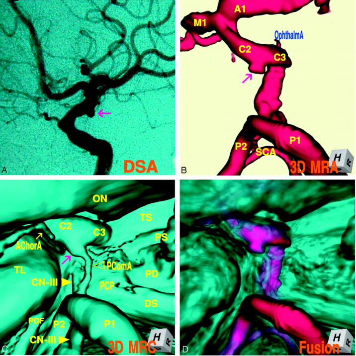
Case 1, Left infundibular dilation at the junction of the internal carotid artery–posterior communicating artery (adult type) in a 75-year-old woman.
A, Digital subtraction angiogram shows a round bulging (arrow) at the supraclinoid internal carotid artery.
B, 3D MR angiogram shows the trapezoid protrusion (arrow) at the supraclinoid internal carotid artery. A1, the first segment of the anterior cerebral artery; M1, the first segment of the middle cerebral artery; C2, the second segment of the internal carotid artery; C3, the third segment of the internal carotid artery; P1, the first segment of the posterior cerebral artery; P2, the second segment of the posterior cerebral artery; SCA, superior cerebellar artery.
C, 3D MR cisternogram, coordinated projection as to the 3D MR angiogram in B, shows an infundibular dilation (arrow) at the junction of the internal carotid artery-posterior communicating artery. A small posterior communicating artery arises at the apex. Intra- and juxtacisternal anatomic elements surrounding an infundibular dilation are visualized. ON, optic nerve; TS, tuberculum sellae; PS, pituitary stalk; PD, pituitary diaphragm; DS, dorsum sellae; PCP, posterior clinoid process; PComA, posterior communicating artery (▹); CN-III, oculomotor nerve (yellow arrow); PDF, petroclinoid dural fold.
D, Fusion image of the 3D MR angiography/cisternography shows the relationship of the bulging finding detected by the 3D MR angiography and its outer wall configuration depicted by the 3D MR cisternography.
Case 2: Right Infundibular Dilation at the Junction of the Internal Carotid Artery–Posterior Communicating Artery (Fetal Type), a 36-Year-Old Woman
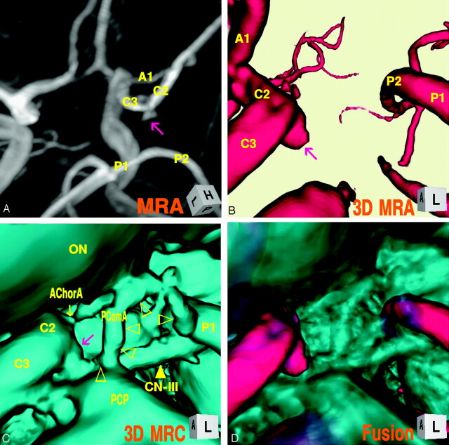
The maximum intensity projection image of MR angiogram (Fig 2A), left superoposterior projection, showed a trapezoid bulging (2.7-mm maximum diameter) at the posterior portion of the supraclinoid internal carotid artery. The 3D MR angiogram (Fig. 2B), left anterior projection, showed an aneurysm-like protrusion with an irregular dome tip. The 3D MR cisternogram (Fig. 2C), coordinated projection as to the 3D MR angiogram in Fig 2B, depicted an infundibular widening with a large posterior communicating artery (fetal type), bent at the right corner of the posterior clinoid process and run tortuously up and down to the posterior cerebral artery. With a fusion image of the 3D MR angiography/cisternography (Fig. 2D) the bulging finding of 3D MR angiography was discerned not an aneurysm but an infundibular dilation.
Fig 2.
Case 2, Right infundibular dilation at the junction of the internal carotid artery–posterior communicating artery (fetal-type), in a 36-year-old woman.
A, Maximum intensity projection image of MR angiogram shows a trapezoidal bulging (arrow) at the posterior portion of the supraclinoid internal carotid artery.
B, 3D MR angiogram shows an aneurysm-like protrusion (arrow).
C, 3D MR cisternogram, coordinated projection as to the 3D MR angiogram B, shows an infundibular widening (large arrow) with a large posterior communicating artery (▹), bended at the posterior clinoid process and run tortuously to the posterior cerebral artery. ON, optic nerve; AChorA, anterior choroidal artery (small arrow); PComA (▹).
D, Fusion image of the 3D MR angiography/cisternography shows not an aneurysm but an infundibular dilation.
Case 3: Left Infundibular Dilation at the Junction of the Internal Carotid Artery–Anterior Choroidal Artery, a 69-Year-Old-Woman
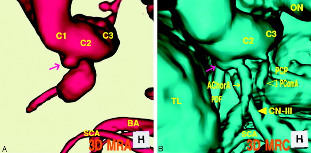
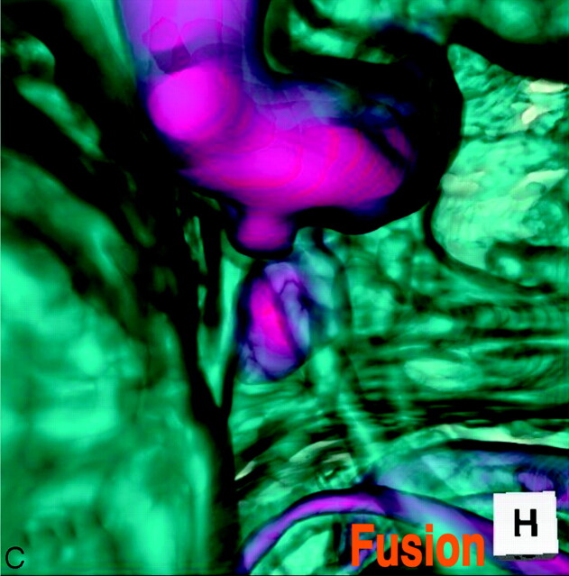
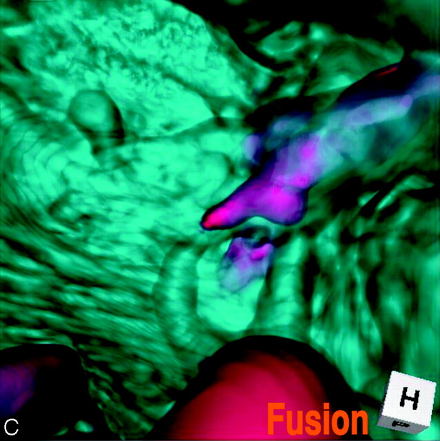
The 3D MR angiogram (Fig 3A), superoinferior projection, showed an aneurysm-like trapezoid bulging (2.7-mm maximum diameter) at the posterior portion of the supraclinoid internal carotid artery. The 3D MR cisternogram (Fig. 3B), coordinated projection as to the 3D MR angiogram in Fig 3A, depicted an infundibular dilation not at the junction of the posterior communicating artery but at the anterior choroidal artery. The anterior choroidal artery arose at the side of the infundibular dilation and ran posterolaterally to the choroidal fissure. The fusion image of the 3D MR angiography/cisternography (Fig. 3C) discriminated an infundibular dilation from an anterior choroidal artery aneurysm.
Fig 3.
Case 3, Left infundibular dilation at the junction of the internal carotid artery–anterior choroidal artery, in a 69-year-old-woman.
A, 3D MR angiogram shows an aneurysm-like trapezoid bulging (arrow). C1, the first segment of the internal carotid artery; BA, basilar artery.
B, 3D MR cisternogram, coordinated projection as to the 3D MR angiogram in A, shows an infundibular dilation (large arrow) at the junction of the anterior choroidal artery (small arrow). PComA (▹); CN-III ([GRAPHIC]); TL, temporal lobe.
C, Fusion image of the 3D MR angiography/cisternography shows an infundibular dilation at the junction of an anterior choroidal artery.
Case 4: Right Infundibular Dilation at the Junction of the Internal Carotid Artery–Posterior Communicating Artery (Fetal Type), Misdiagnosed as an Aneurysm and Treated Surgically, a 44-Year-Old Woman
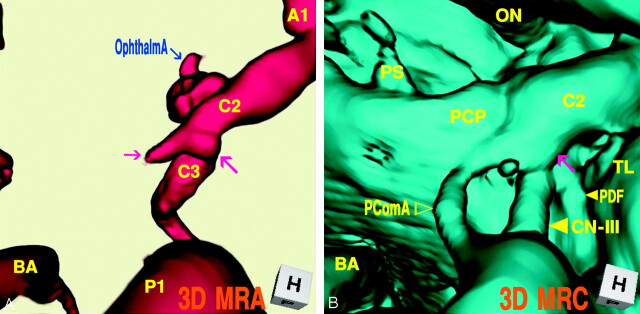
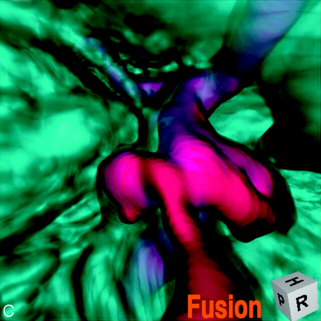
This patient was misdiagnosed and operated on for an unruptured internal carotid–posterior communicating artery aneurysm with a bleb. Operative findings disclosed a simple infundibular widening at the origin of a large posterior communicating artery, and coating of the protrusive portion was performed in the operation. The MR angiography/cisternography was examined postoperatively. The 3D MR angiogram (Fig 4A), superoinferior projection, showed an aneurysm-like protrusion with a round dome and a conical bleblike elongation (3.2-mm maximum diameter) at the posteromedial portion of the supraclinoid internal carotid artery. The 3D MR cisternogram (Fig. 4B), coordinated projection as to the 3D MR angiogram in Fig 4A, depicted an infundibular dilation with a large posterior communicating artery (fetal type). The posterior communicating artery was bent at the right lateral edge of the posterior clinoid process and run posteriorly to the posterior cerebral artery. Fusion image of the 3D MR angiography/cisternography (Fig. 4C) visualized the anatomic relationship of an aneurysm-like complex to a large posterior communicating artery; thus the bulging portion was diagnosed as not an aneurysm with a bleb but an infundibular dilation accompanying a large posterior communicating artery.
Fig 4.
Case 4, Right infundibular dilation at the junction of the internal carotid artery–posterior communicating artery (fetal type), misdiagnosed as an aneurysm and treated surgically, in a 44-year-old woman.
A, 3D MR angiogram shows an aneurysm-like protrusion (large arrow) and a conical bleblike elongation (small arrow).
B, 3D MR cisternogram, coordinated projection as to the 3D MR angiogram in A, shows an infundibular dilation (arrow) with a large posterior communicating artery. PDF (small arrow); CN-III (large arrow); PComA (▹).
C, Fusion image of the 3D MR angiography/cisternography shows the anatomic relationship of an aneurysm-like complex to a large posterior communicating artery, and indicating not an aneurysm but an infundibular dilation.
Case 5: Left Internal Carotid Artery–Posterior Communicating Artery Aneurysm, a 66-Year-Old Woman
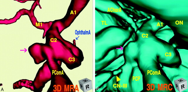
The 3D MR angiogram (Fig 5A), right superoposterior projection, showed an aneurysm with an irregular dome (3.9 mm in the maximum diameter) at the junction of the internal carotid artery–posterior communicating artery. The 3D MR cisternogram (B), coordinated projection to the 3D MR angiogram in Fig 5A, depicted an aneurysm and a large posterior communicating artery (fetal type). The dome extended inferoposteromedially toward the left lateral edge of the posterior clinoid process and the left oculomotor nerve. Fusion image of the 3D MR angiography/cisternography (Fig. 5C) clearly visualized the aneurysm complex in relation to its perianeurysmal environment.
Fig 5.
Case 5, Left internal carotid artery–posterior communicating artery aneurysm, in a 66-year-old woman.
A, 3D MR angiogram shows an aneurysm with an irregular dome (arrow).
B, 3D MR cisternogram, coordinated projection as to the 3D MR angiogram in A, shows an aneurysm (arrow) and a large posterior communicating artery. AChorA, anterior choroidal artery; CN-III (arrow).
C, Fusion image of the 3D MR angiography/cisternography shows the aneurysm complex in relation to its perianeurysmal environment.
Discussion
With use of MR angiography for screening of cerebrovascular lesions, vascular bulging is frequently observed at the supraclinoid portion of the internal carotid artery.2,9,10 Infundibular dilation most often affects the origin of the posterior communicating artery at its junction of the internal carotid artery. Incidence of infundibular dilation detected by angiography or at autopsy ranges from 7% to 25%, and increases with age.4–6 Angiographic criteria for infundibular dilation include round or conical in shape, <3 mm in the maximum diameter, without aneurysmal neck, and with a posterior communicating artery arising from its apex.5 Angiographic findings for this lesion, however, are difficult to interpret, and it is sometimes misdiagnosed and treated as an aneurysm.9,10 In particular, when the posterior communicating artery does not filled well or appears very small, and when the anatomic relationship of the protrusion to the internal carotid artery is not clearly depicted, it is difficult to distinguish an infundibular dilation and enlarged origin of the normal posterior communicating artery from an aneurysm.9–12
MR angiography obtained by 3D TOF sequence represents not the luminal morphology as shown by angiography and CT angiography,13,14 but inflow effect related mainly to peak inflow velocity within the vessel lumen during the data acquisition process.1,3 The magnitude of signal intensity of MR angiography is complicated and affected by several factors. Loss of signals occurs from spin saturation phenomenon due to slow flow, phase dispersion due to complex and disturbed flow conditions, and susceptibility or partial volume effects.3 Decrease in signal intensity and inhomogeneous signal intensity distribution are often observed within an aneurysm and at the origin of the branching site of vessels. In addition, when the flow condition within the posterior communicating artery varies in complexity according to the directions of collateral flow in the circle of Willis,15 inflow effect within the vessels may decrease, and this may result in poor visualization of the posterior communicating artery.
In contrast, MR cisternography depicts the vascular structures with profoundly low signal intensity, and cranial nerves and brain parenchyma with moderately low signal intensity; outer borderline of intracisternal anatomic elements is well demarcated by the profoundly hyperintense adjacent subarachnoid CSF.7,8,16 3D reconstruction of volume data acquired by MR cisternography can depict the morphologically fine outer wall configuration of the vessels in relation to the surrounding intra- and juxtacisternal structures.7,8
By using a fusion imaging technique of 3D MR cisternography/angiography, vascular structure of 3D MR cisternography and 3D MR angiography is composed in a single image.7,8 With a 3D MR angiography alone, it may be difficult to depict the hypoplastic or small size (adult-type) posterior communicating artery associated with an infundibular dilation. In case of the well-developed (fetal-type) posterior communication artery but with a bended and tortuous running course, the whole shape of the vessel may not be shown owing to a decrease in inflow effect within a vessel. In contrast, 3D MR cisternography can depict the vascular contour unrelated to the intraluminal flow conditions; however, the extent of cisternographic view is limited primarily within a cisternal space and complicated by the nonvascular elements in the intra- and juxtacisternal space. With a fusion imaging technique of 3D MR cisternography/angiography, vascular structures depicted on the 3D MR cisternogram can be discriminated by referencing the coordinated 3D MR angiogram. Vascular bulging related to inflow effect detected by MR angiography may be assessed from the viewpoint of the outer wall configuration of the corresponding internal carotid artery by overlapping the coordinated MR cisternogram.
In conclusion, when a vascular bulging of the internal carotid artery is detected by MR angiography, assessment with a fusion imaging technique of 3D MR cisternography/angiography may provide useful information to distinguish an infundibular dilation and enlarged origin of the normal posterior communicating artery from an aneurysm. This imaging technique can be a feasible addition to a noninvasive screening of cerebrovascular lesions with MR angiography alone.
Footnotes
Presented in part at the 14th annual meeting of Japanese Society for Detection of Asymptomatic Brain Disease, July 1–2, 2005, Nagoya, Japan.
References
- 1.Adams WM, Laitt RD, Jackson A. The role of MR angiography in the pretreatment assessment of intracranial aneurysms: a comparative study. AJNR Am J Neuroradiol 2000;21:1618–28 [PMC free article] [PubMed] [Google Scholar]
- 2.Okahara M, Kiyosue H, Yamashita M. Diagnostic accuracy of magnetic resonance angiography for cerebral aneurysms in correlation with 3D-digital subtraction angiographic images. a study of 133 aneurysms. Stroke 2002;33:1803–808 [DOI] [PubMed] [Google Scholar]
- 3.Satoh T, Onoda K, Tsuchimoto S. Visualization of intraaneurysmal flow patterns with transluminal flow images of 3D MR angiograms in conjunction with aneurysmal configurations. AJNR Am J Neuroradiol 2003;24:1436–45 [PMC free article] [PubMed] [Google Scholar]
- 4.Salyzman GF. Infundibular widening of the posterior communicating artery studied by carotid angiography. Acta Radiol 1959;51:415–21 [DOI] [PubMed] [Google Scholar]
- 5.Taveras LM, Wood EH. Diagnostic Neuroradiology. 2nd ed. Baltimore, Williams & Wilkins,1976. , pp584–87
- 6.Ebina K, Ohkuma H, Iwabuchi T. An angiographic study of incidence and morphology of infundibular dilation of the posterior communicating artery. Neuroradiology 28 1986;28:23–29 [DOI] [PubMed] [Google Scholar]
- 7.Satoh T, Omi M, Ohsako C, et al. Visualization of aneurysmal contours and perianeurysmal environment with conventional and transparent 3D MR cisternography. AJNR Am J Neuroradiol 2005;26:313–18 [PMC free article] [PubMed] [Google Scholar]
- 8.Satoh T, Omi M, Ohsako C, et al. Influence of perianeurysmal environment on the deformation and bleb formation of the unruptured cerebral aneurysm. Assessment with fusion imaging of 3D MR cisternography and 3D MR angiography. AJNR Am J Neuroradiol 2005;26:2010–18 [PMC free article] [PubMed] [Google Scholar]
- 9.Endo S, Furuichi S, Takabe, et al. Clinical study of enlarged infundibular dilation of the origin of the posterior communicating artery. J Neurosurg 1995;83:421–25 [DOI] [PubMed] [Google Scholar]
- 10.Kubota T, Niwa J, Tanigawara T, et al. Differential diagnosis between aneurysm and infundibular dilation in the IC-PC region with 3D-CTA. No Shinkei Geka (Tokyo)2000;28:31–39 [in Japanese with English abstract] [PubMed] [Google Scholar]
- 11.Epstein F, Ransohoff J, Budzilovich GN. The clinical significance of junctional dilation of the posterior communicating artery. J Neurosurg 1970;33:529–31 [DOI] [PubMed] [Google Scholar]
- 12.Marshman LAG, Ward PJ, Walter PH, et al. The progression of an infundibulum to aneurysm formation and rupture: case report and literature review. Neurosurgery 1998;43:1445–49 [DOI] [PubMed] [Google Scholar]
- 13.Satoh T. Transluminal imaging with perspective volume rendering of computed tomographic angiography for the delineation of cerebral aneurysms. Neurol Med Chir (Tokyo)2001;41:425–30 [DOI] [PubMed] [Google Scholar]
- 14.Satoh T, Onoda K, Tsuchimoto S. Intra-operative evaluation on aneurysmal architecture. Comparative study with transluminal imaging of 3D MR and CT angiograms. AJNR Am J Neuroradiol 2003;24:1975–81 [PMC free article] [PubMed] [Google Scholar]
- 15.Hartkamp MJ, van der Grond J, van Everdingen KJ. Circle of willis collateral flow investigated by magnetic resonance angiography. Stroke 1999;30:2671–78 [DOI] [PubMed] [Google Scholar]
- 16.Rubinstein D, Sandberg EJ, Breeze RE, et al. T2-weighted three-dimensional turbo spin-echo MR of intracranial aneurysms. AJNR Am J Neuroradiol 1997;18:1939–43 [PMC free article] [PubMed] [Google Scholar]


