Abstract
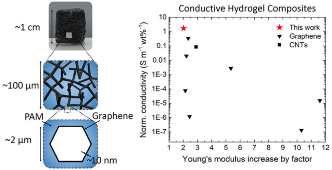
The fabrication of electrically conductive hydrogels is challenging as the introduction of an electrically conductive filler often changes mechanical hydrogel matrix properties. Here, we present an approach for the preparation of hydrogel composites with outstanding electrical conductivity at extremely low filler loadings (0.34 S m–1, 0.16 vol %). Exfoliated graphene and polyacrylamide are microengineered to 3D composites such that conductive graphene pathways pervade the hydrogel matrix similar to an artificial nervous system. This makes it possible to combine both the exceptional conductivity of exfoliated graphene and the adaptable mechanical properties of polyacrylamide. The demonstrated approach is highly versatile regarding porosity, filler material, as well as hydrogel system. The important difference to other approaches is that we keep the original properties of the matrix, while ensuring conductivity through graphene-coated microchannels. This novel approach of generating conductive hydrogels is very promising, with particular applications in the fields of bioelectronics and biohybrid robotics.
Keywords: Hydrogel, graphene, electrical conductivity, bioelectronics
Electrically conductive hydrogels are gaining increasing interest, as they can serve as biosensors,1−4 bioelectronics5−7 and scaffolds for functional tissues,8 such as cardiac9,10 and nervous tissue.11,12 They are also intensely discussed as materials for biohybrid robotics, where the contraction of electrically excitable cells leads to actuation.13 In general, hydrogels are known as superabsorbents and can naturally contain and hold large amounts of water or aqueous solutions. Intrinsic conductivity in conductive hydrogels can originate from ionic and electrical conductivity. For ionic conductivity, the hydrogel can be viewed as a polymer network swollen in an electrolyte.1 Electrical conductivity in intrinsically conductive hydrogels is based on the presence of conjugated π-electron systems, where π-electrons can move freely and serve as mobile charge carriers, but these conjugated structures are inherently rigid and compromise the mechanical properties.5 Maintaining the physicochemical properties of hydrogels such as toughness, stretchability, and sustaining multiple cyclic compressions remains a challenge in the development of conductive hydrogels. Strategies to make intrinsically nonconductive hydrogels conductive are, first, by in situ polymerization, second, by the addition of conductive filler materials by blending or by postpolymerization, or third, by coating procedures.1,14 Filler materials that are typically used include gold or iron oxide nanoparticles, carbon nanomaterials such as exfoliated graphene, reduced graphene oxide, carbon nanotubes (CNTs), or conductive polymers.14−17 A particularly technically relevant filler material is graphene. Since its discovery in 2004,18,19 graphene has become a very popular material with numerous applications as it offers excellent mechanical and chemical properties including a very high Young’s modulus (1000 GPa)20 as well as a high charge carrier density and mobility resulting in an outstanding electrical conductivity of up to 6 × 10⁵ S m–1.21,22 Graphene is a two-dimensional carbon nanomaterial consisting of a monolayer of sp2-hybridized carbon atoms, which form a hexagonal honeycomb structure.21 When one atom-layer thick, graphene absorbs 2.3% of incident white light, which means that multilayered graphene is still transparent, when sufficiently thin.23 This is particularly relevant for hydrogels, which are often optically transparent.
In this work, we focused on a hydrogel composite made from polyacrylamide (PAM) in combination with exfoliated graphene (EG). Polyacrylamide is a well-known synthetic hydrogel with a stiffness adjustable through altering the amount of cross-linker methylene-bis-acrylamide, leading to a stiffness from 0.5 up to 740 kPa.24 Additionally, cross-linked polyacrylamide is biocompatible, thus making it a suitable material for biological applications (Figure S1). In general, electrical conductivity is promoted in hydrogels filled with conductive nanoparticles after reaching the percolation threshold at certain filler degrees.1 The amount of filler is a critical aspect as high filler amounts alter the properties of the matrix material, often leading to mechanical reinforcement of the matrix, thereby changing the mechanical properties.25
To reach a sufficiently high electrical conductivity but to prevent reinforcement of the matrix, we herein use a different strategy: We restrict the conductive pathways to microchannels, similar to nerves in the body. The conductive pathways are based on microengineered graphene framework structures, which are embedded into a polyacrylamide hydrogel matrix to generate a microchannel-containing conductive hydrogel. The striking benefit of this approach is that the filler material is not mixed with the hydrogel matrix, but the conductive pathways are predetermined by the graphene framework; only in these regions is conductive filler material present. Thus, 99.9% of the hydrogel matrix is filler-free;26 hence, the overall hydrogel matrix is kept free from filler materials, and its properties are maintained. The structure of the composites was examined by scanning electron microscopy and X-ray microtomography (micro-CT). We investigated the response of the material to cyclic compression tests and analyzed the electrical conductivity. The amount of filling material was adjusted, and tailorable specific electrical conductivities were achieved at extremely low filler concentrations.
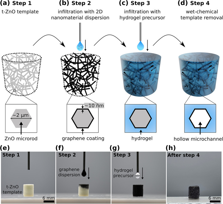
Our general concept for the fabrication of conductive hydrogels is based on a template-assisted approach and schematically shown in Figure 1. 3D networks made from tetrapodal-shaped zinc oxide microparticles (t-ZnO) serve as versatile templates.26 In brief, t-ZnO powder is produced utilizing the so-called flame transport synthesis.27,28 For producing the templates, a defined amount of loose t-ZnO powder is pressed to templates using a rigid mold with defined geometry, followed by an annealing step at elevated temperatures (1150 °C, 5 h). The specific shape of the t-ZnO results in templates with an interconnected arm structure allowing high control over porosity (up to 94.7%), pore size, and geometry of the final template.26 The template is superhydrophilic, and thus, aqueous dispersions of 2D nanomaterial (e.g., graphene, CNTs) can be infiltrated using a drop-casting process29 (Figure 1b). The 2D material covers the surface of the ZnO tetrapods while the water evaporates. By tailoring the concentration of the dispersion and by repeating the infiltration process several times, the thickness of the resulting 2D nanomaterial layer can be adjusted (up to 10 nm).26 In a following step, the hydrogel is introduced by infiltrating a hydrogel precursor solution into the template such that the entire free volume (∼94%) is filled up (Figure 1c). After polymerization of the hydrogel, the t-ZnO template is removed by wet-chemical treatment. This results in a hydrogel that contains hollow microchannels covered with graphene. Raman spectroscopy revealed that no covalent bonding between PAM and EG formed, but the bonding is based on structural attachment and van der Waals forces (Figure S2). The overall structure of the microchannel network resembles that of the interconnected network of tetrapodal ZnO in the sense of a bottom-up fabrication (Figure 1d).30,31 A schematic representation of the cross-section of a t-ZnO arm and the resulting microchannel after ZnO dissolution, respectively, is given in Figure 1a–d. An image sequence of the infiltration processes employing exfoliated graphene as the conductive filler and polyacrylamide as the hydrogel is shown in Figure 1e–h. The PAM network and PAM-EG samples are biocompatible (Figure S1). The whole fabrication process can be adjusted to other 0D, 1D, and 2D nanomaterials [e.g., gold nanoparticles (0D), CNTs (1D), reduced graphene oxide (2D), MXene (e.g., Ti3C2Tx) (2D)] as well as to other hydrogel systems (e.g., poly-N-isopropylacrylamide) leading to a wide variety of possible applications.
Figure 1.
Fabrication process for conductive microchannel-containing hydrogels. (a–d) Schematic illustration of the preparation steps for a 3D network composite consisting of a hydrogel matrix and microchannels coated with an electrically conductive 2D filler material (here with exfoliated graphene). Images of the infiltration process: (e) t-ZnO template before infiltration, (f) drop-casting process with 2D filler material (Step 2), (g) after complete infiltration, the hydrogel precursor solution is drop-cast on the template until it is filled completely (Step 3), (h) polyacrylamide-exfoliated graphene (PAM-EG) composite (EG: 0.32 vol %).
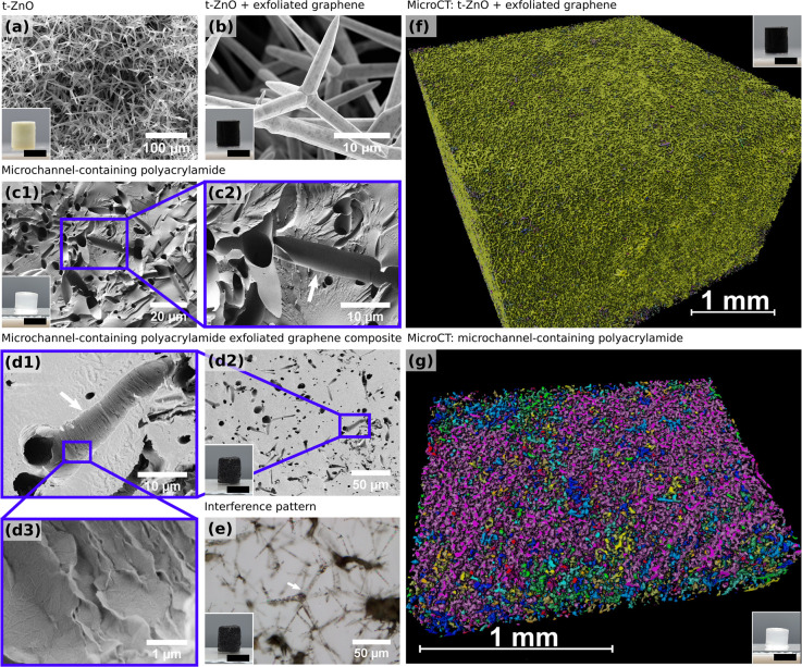
Scanning electron microscopy (SEM) reveals the structure of the microchannels in the hydrogel. SEM images of a t-ZnO template, a t-ZnO template coated with exfoliated graphene (t-ZnO-EG), a microchannel-containing polyacrylamide (PAM) hydrogel, and a polyacrylamide-exfoliated graphene (PAM-EG) composite with conductive microchannels are shown in Figure 2a–d. The insets show macroscopic images of the t-ZnO and t-ZnO-EG templates and the swollen hydrogel samples. Figure 2b and the inset show the coating of t-ZnO tetrapods by exfoliated graphene sheets demonstrating the uniform coating of t-ZnO with EG by the drop-casting method.26 Removing water from hydrogels results in shrinkage; thus, no quantitative statement about the channel size in the swollen hydrogel is possible. The tetrapodal structure originating from the sacrificial ZnO templates shown in Figure 2a is clearly visible in the hydrogel samples (Figure 2c,d). The arrows in Figure 2c,d each show a channel that has been cut into two halves. Microchannel-containing polyacrylamide shows very smooth channel surfaces (Figure 2c), while in the conductive hydrogels, the channel surface is uneven and rippled (Figure 2d), which shows the characteristic wrinkled structure of multilayered graphene.32,33 It is evident that the conductive filler material coats the channel walls and did not diffuse into the hydrogel matrix. This is also supported by the fact that, in the SEM, the hydrogel matrix was prone to charging, whereas the conductive channels were not (Figure S3). Multilayered graphene is known to show interference patterns on SiO2 due to strong scattering centers.34 Dehydrated PAM-EG samples cut with an ultramicrotome and mounted on a Si-wafer were analyzed with light microscopy in epi-illumination mode, and observed interference patterns are highlighted in Figure 2e. Figure 2f,g shows rendered micro-CT 3D images in a region of interest of a t-ZnO-EG and a network PAM scaffold, respectively. The colors in the 3D renderings designate connected components. The connectivity of the tetrapods in the ZnO-EG sample was calculated as 97.1% and that of the microchannel network in the PAM sample as 70.6%. Image artifacts and lower image contrast due to movements of the sample in the beam likely influenced the calculated connectivity of the network PAM sample. The decrease in connectivity in the hydrogel sample in comparison with the sacrificial template of around 30% can be explained by the hydrogel system itself, as swelling of the hydrogel could lead to the destruction of original connections and pathways. Nevertheless, as shown in Figure 2g, one connected region (purple color) extends over the entire region of interest in the network PAM scaffold.
Figure 2.
Representative SEM micrographs of the structure of (a) t-ZnO templates, (b) t-ZnO template coated with exfoliated graphene (t-ZnO-EG), (c) microchannel-containing polyacrylamide (PAM), and (d) microchannel-containing polyacrylamide-exfoliated graphene (PAM-EG) composites. White arrows in parts c and d indicate a channel that has been cut into two halves. The channel surface of the polyacrylamide gel is smooth and homogeneous, while the channels of the microchannel-containing PAM-EG composite are covered with exfoliated graphene. The characteristic wrinkled structure of multilayered graphene is visible in the high-magnification image (d3). (e) A thin layer of PAM-EG composite on a SiO2 wafer imaged with light microscopy shows an interference pattern (arrows) of multilayered graphene assembled on tetrapod arms. (f, g) Rendered X-ray microtomography 3D images of t-ZnO-EG and network PAM, respectively. The colors in the 3D renderings designate connected components. Inset scale bars: 6 mm.
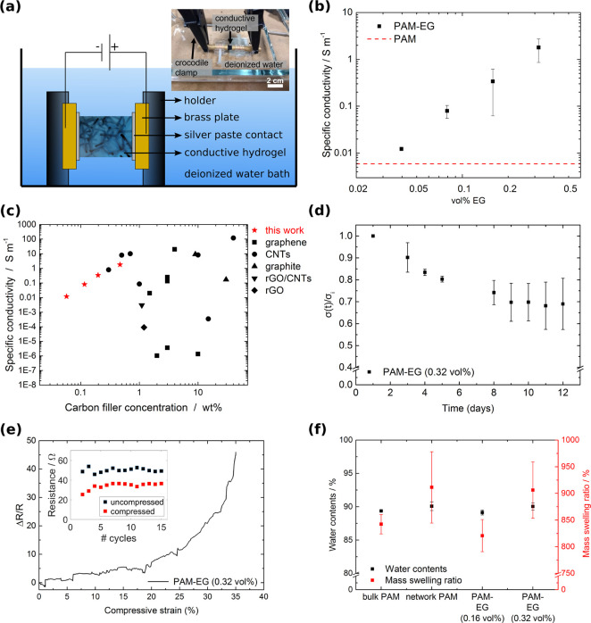
To determine the electrical conductivity of the PAM-EG composites, the two-point method was used, and triplicates of samples were measured in water. The setup is shown in Figure 3a. The voltage was increased from −1 to +1 V in step sizes of 0.05 V while measuring the current. All samples showed ohmic behavior (Figure S4). Figure 3b shows the specific conductivity of PAM-EG composites as a function of the filler concentration. The pure PAM samples exhibited a conductivity of 0.006 S m–1. Specific conductivity increased by more than 3 orders of magnitude with an increasing amount of filler material indicating the presence of percolating pathways consisting of graphene. Conduction between the graphene flakes is possible by either tunneling or direct contact.22 By adding increasing amounts of EG to the system, more direct contacts form between graphene sheets and, thus, contribute to a higher conductivity. The addition of 0.04 vol % EG results in a conductivity of 0.012 S m–1 corresponding to an increase of 50% in comparison to the pure PAM samples. A filler fraction of 0.32 vol % results in a conductivity of 1.8 S m–1. Comparing these values to the conductivity of heart tissue (around 0.1 S m–1)35 shows that the values achieved here make the material interesting for cardiac tissue engineering, where engineered cardiac patches are used for treating damaged heart tissue after a myocardial infarction.15,36 We exceed the value of heart tissue already for small filler concentrations of 0.16 vol % EG with a conductivity of 0.34 S m–1. Compared to previous approaches, shown in Figure 3c, our fabrication method allows us to decrease the amount of filler material by more than 1 order of magnitude, still exceeding the DC conductivity of heart tissue. Predetermining the conductive pathways, which pervade the material like an artificial nervous system, is thus beneficial to reach high conductivities at low filler concentration.
Figure 3.
Electrical conductivity of PAM-EG composites: (a) Schematic of the conductivity measurement setup. The sample was mounted with silver paste in a customized sample holder. The measurement took place in water to prevent drying of the hydrogel composites. (b) Specific conductivity of the PAM-EG composite as a function of EG concentration. Error bars represent standard deviation, N = 3. (c) Comparison of the conductivities of electrically conductive hydrogels based on carbon filler material. The red stars indicate the results for the PAM-EG composites from this work. The list of all electrically conductive hydrogels with corresponding references are shown in Table S1 in the Supporting Information. (d) Normalized conductivity (σ(t)/σ0) as a function of time. PAM-EG with 0.32 vol % measured over 12 days (N = 3). (e) Normalized change in resistance during cyclic compression of up to 35%. The inset shows the resistance values for the uncompressed and compressed state for 15 consecutive cycles. (f) Water content and mass swelling ratio of different samples.
For all applications, a sufficient long-term stability of the samples is required. To demonstrate the stability of our samples at extended times, the relative change in specific conductivity of PAM-EG (0.32 vol %) over a storage time of 12 days is shown in Figure 3d. During the first 9 days, the conductivity dropped by 31%. This is probably caused by further swelling of the hydrogel and redispersion of EG in water resulting in a partial destruction of conductive pathways. After 9 days, no further decrease of the conductivity was measured. Additionally, resistance measurements during cyclic compression of up to 35% for 15 cycles were performed. Figure 3e shows the normalized change in resistance during a compression of up to 35%. Upon compression, the change in resistance increased. This result suggests that more conductive pathways formed. Thus, PAM-EG composites may be a suitable material for pressure sensing applications. The inset shows the resistance values for the uncompressed and compressed state for 15 cycles. After the first cycle, the resistance of the uncompressed state increased by approximately 30%. This might be due to rearrangements of graphene sheets and partial destruction of conductive pathways. However, the resistance of the uncompressed and compressed state stayed at a constant level during the subsequent cycles demonstrating that the material is able to withstand cyclic compression. Swell tests in Figure 3f show that all samples exhibit a water content of approximately 90% and a mass swelling ratio of around 870%.
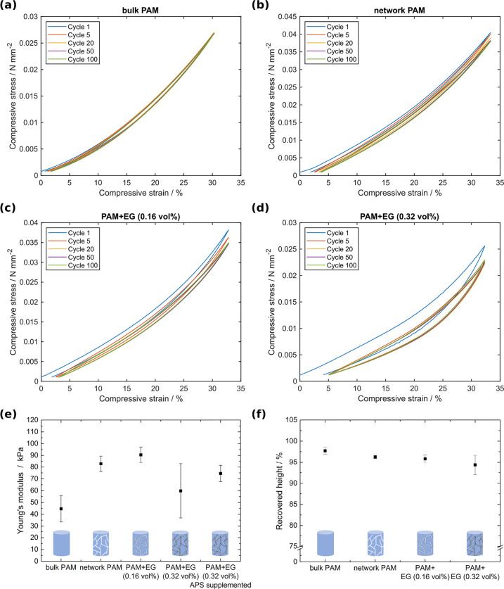
The mechanical properties of the prepared hydrogels were tested via cyclic compression tests. The microchannel-containing, conductive PAM-EG composites with two different filler amounts were compared to microchannel-containing PAM networks and bulk PAM samples. In Figure 4a–d, representative cyclic compressive stress–strain curves of all hydrogels and composites are shown for 100 consecutive cycles up to a compressive strain of 33%. All samples are viscoelastic due to the viscoelasticity of the hydrogel. The microchannel-containing PAM-EG hydrogels revealed a distinctive hysteresis of the initial cycle. This might be attributed to a preconditioning phenomenon:37 During the first cycle, the system adapts to the applied force including the rearrangement of graphene sheets, material interactions, and breaking of van der Waals forces. Consecutively, the system stays in an equilibrium state displaying no further significant change in the stress–strain curve. Figure 4e shows the compressive Young’s modulus determined up to a strain of 5% of the different hydrogel types over all cycles except the initial one. In comparison to the bulk PAM hydrogels (E = 45 kPa) the Young’s modulus of microchannel-containing PAM is 83 kPa and thus almost twice that of the bulk material. This can be explained by the introduction of water-filled microchannels into the hydrogel matrix, which leads to an enhanced stiffness as water generally has a high compressive bulk modulus (2.25 GPa).38
Figure 4.
(a−d) Representative cyclic stress−strain curves for 33% strain of bulk PAM, network PAM, and PAM-EG composites with 0.16 and 0.32 vol % filler content, respectively. All samples show viscoelastic behavior and a slight hysteresis. The microchannel-containing PAM-EG hydrogels revealed a distinctive hysteresis of the initial cycle, which is the result of a preconditioning phenomenon. (e) Initial Young’s modulus up to 5% strain. Error bars depict standard deviation, N = 3. (f) Recovered height after 100 cycles. Error bars depict standard deviation, N = 3.
The compressive Young’s moduli of microchannel-containing PAM-EG composites with 0.16 and 0.32 vol % filler increased by 102% to 91 kPa and by 33% to 60 kPa in comparison to bulk PAM, respectively. The microchannel-containing PAM-EG composites with 0.16 vol % filler reveal no further significant increase of the compressive modulus compared to microchannel-containing PAM hydrogels (increase by 10%) implying that the introduced EG does not induce a reinforcement of the material. This shows that our strategy to introduce conductive pathways is an excellent way to produce conductive hydrogels while not altering the matrix properties. However, for the PAM-EG composites with 0.32 vol % filler, a decrease in Young’s modulus was observed in contrast to PAM-EG composites with 0.16 vol % filler. This might result from interactions between EG and the components used in PAM polymerization such as the initiator ammonium persulfate (APS). APS is used in the production of graphene oxide sheets where it assists in enhanced oxidation of graphite flakes.39 By implication, this means that the decomposition of APS by the exfoliated graphene leads to a reduced number of formed free radicals, which are participating in the polymerization, resulting in a reduced number of polymer chains. Thus, the chains exhibit a longer chain length and, therefore, a higher elasticity. Nevertheless, by adjusting the amount of APS and the catalyst N,N,N′,N′-tetramethylethylenediamine (TEMED), the Young’s modulus could be restored to 74.5 kPa (Figure 4e).
The recovered height after 100 cycles and a compression of 33% is above 94% for all sample types indicating a good mechanical stability (Figure 4f). The slightly decreased recovered height for the PAM-EG composites might be attributed to the rearrangement of graphene flakes during the initial cycles as addressed above. The ultimate compressive strain of all samples is around 67% for all sample types with an ultimate compressive stress of approximately 0.1 N mm–2 (Figure S6).
In summary, we presented a highly versatile fabrication method for the preparation of microchannel-containing conductive hydrogels. The incorporation of exfoliated graphene frameworks into a polyacrylamide matrix generates conductive pathways, which pervade the hydrogel matrix similar to an artificial nervous system. This approach results in a very high conductivity of 0.34 S m–1 at an extremely low filler concentration of 0.16 vol % EG. Simultaneously, the effect of the incorporated EG on the mechanical properties of the hydrogel matrix is kept remarkably low, only leading to an increase of Young’s modulus of 10%.
In Figure 5, the weight-percent normalized conductivity is depicted as a function of the increase in Young’s modulus. Compared to other conductive hydrogel systems, our approach makes it possible to achieve excellent electrical conductivities while maintaining the hydrogel matrix properties.
Figure 5.
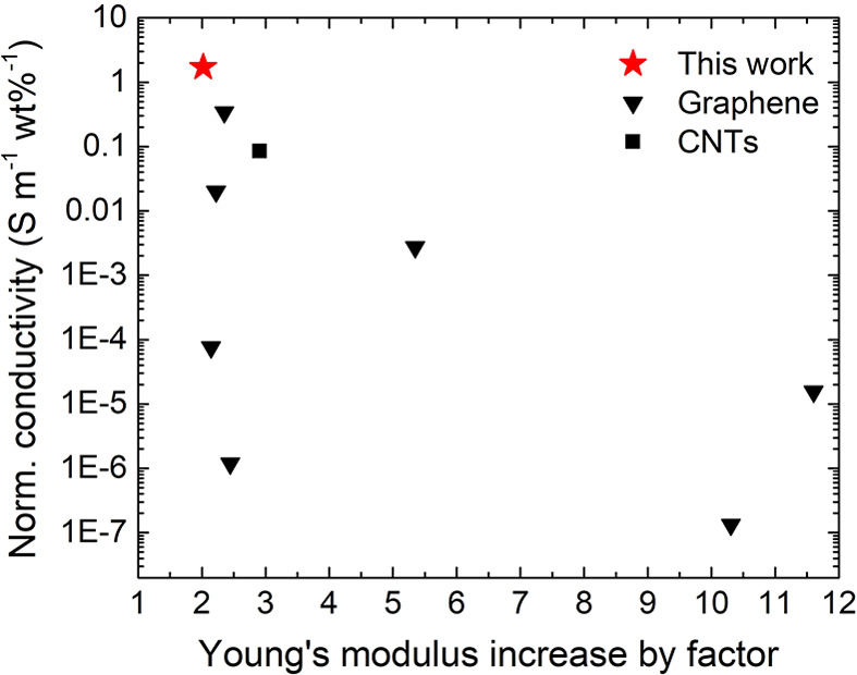
Ashby plot showing the weight-percent normalized conductivity as a function of increase in Young’s modulus for different conductive hydrogel systems based on carbon filler material. The red star indicates the results for the PAM-EG composites from this work. The list of all electrically conductive hydrogels with corresponding references is shown in Table S2 in the Supporting Information.
Further, the material provides a microchannel system that can be beneficial for liquid transport or drug delivery as the incorporation of such a microchannel network enhances diffusion shown in Figure S7. Furthermore, the conductive hydrogel is adaptable in its conductivity, porosity, mechanical properties, size, and shape while, additionally, the fabrication method is adaptable to other 1D and 2D nanomaterials (e.g., reduced graphene oxide, CNTs, MXenes (e.g., Ti3C2Tx), gold nanorods) as well as to other hydrogel systems (e.g., poly-N-isopropylacrylamide) leading to a wide variety of possible applications, e.g., in bioelectronics, biosensing, and biohybrid soft robotics.
Acknowledgments
We thank Helen Krol for assistance in the cell culture lab. The authors acknowledge the support by Dr. Fabian Wilde in setting up the P05 beamline at PETRA III, DESY for the micro-CT experiments. C.A. and C.S.-U. thank the Volkswagen Foundation for funding the project “Molecularly controlled, stimuli-sensitive hydrogels for dynamically adjustable biohybrid actuators”. M.H., F.S., F.R., and R.A. acknowledge funding by the German Research Foundation (Deutsche Forschungsgemeinschaft, DFG) under contract AD183/27-1. M.H., F.S., F.R., C.S.-U., and R.A. also thank the German Research Foundation for funding through the RTG 2154. C.S.-U. acknowledges support through the Max Planck School Matter to Life supported by the German Federal Ministry of Education and Research (BMBF) and the DFG for funding through the collaborative Research Centre CRC 1261 “Magnetoelectric Sensors: From Composite Materials to Biomagnetic Diagnostics”, project B7. R.R.S. and C.S.-U. acknowledge funding by the DFG under Germany’s Excellence Strategy 2082/1-390761711 (3D Matter Made to Order). R.R.S. also acknowledges funding by the BMBF project NanoPatho, FKZ 13N14476. This project has received funding from the European Union’s Horizon 2020 research and innovation program under grant agreement 785219 (GrapheneCore2) and 881603 (GrapheneCore3).
Supporting Information Available
The Supporting Information is available free of charge at https://pubs.acs.org/doi/10.1021/acs.nanolett.0c04375.
Experimental details, supplementary figures, and lists of conductive hydrogel composites and their electric and mechanical properties (PDF)
Author Contributions
○ C.A. and M.H. contributed equally to this work. All authors have given approval to the final version of the manuscript.
The authors declare no competing financial interest.
Supplementary Material
References
- Distler T.; Boccaccini A. R. 3D printing of electrically conductive hydrogels for tissue engineering and biosensors - A review. Acta Biomater. 2020, 101, 1–13. 10.1016/j.actbio.2019.08.044. [DOI] [PubMed] [Google Scholar]
- Jung I. Y.; Kim J. S.; Choi B. R.; Lee K.; Lee H. Hydrogel Based Biosensors for In Vitro Diagnostics of Biochemicals, Proteins, and Genes. Adv. Healthcare Mater. 2017, 6, 1601475. 10.1002/adhm.201601475. [DOI] [PubMed] [Google Scholar]
- Shin S. R.; Farzad R.; Tamayol A.; Manoharan V.; Mostafalu P.; Zhang Y. S.; Akbari M.; Jung S. M.; Kim D.; Comotto M.; Annabi N.; Al-Hazmi F. E.; Dokmeci M. R.; Khademhosseini A. A Bioactive Carbon Nanotube-Based Ink for Printing 2D and 3D Flexible Electronics. Adv. Mater. 2016, 28, 3280–3289. 10.1002/adma.201506420. [DOI] [PMC free article] [PubMed] [Google Scholar]
- Song H. S.; Kwon O. S.; Kim J. H.; Conde J.; Artzi N. 3D hydrogel scaffold doped with 2D graphene materials for biosensors and bioelectronics. Biosens. Bioelectron. 2017, 89, 187–200. 10.1016/j.bios.2016.03.045. [DOI] [PubMed] [Google Scholar]
- Fu F.; Wang J.; Zeng H.; Yu J. Functional Conductive Hydrogels for Bioelectronics. ACS Mater. Lett. 2020, 2, 1287–1301. 10.1021/acsmaterialslett.0c00309. [DOI] [Google Scholar]
- Zheng C.; Lu K.; Lu Y.; Zhu S.; Yue Y.; Xu X.; Mei C.; Xiao H.; Wu Q.; Han J. A stretchable, self-healing conductive hydrogels based on nanocellulose supported graphene towards wearable monitoring of human motion. Carbohydr. Polym. 2020, 250, 116905. 10.1016/j.carbpol.2020.116905. [DOI] [PubMed] [Google Scholar]
- Ding Q.; Xu X.; Yue Y.; Mei C.; Huang C.; Jiang S.; Wu Q.; Han J. Nanocellulose-Mediated Electroconductive Self-Healing Hydrogels with High Strength, Plasticity, Viscoelasticity, Stretchability, and Biocompatibility toward Multifunctional Applications. ACS Appl. Mater. Interfaces 2018, 10, 27987–28002. 10.1021/acsami.8b09656. [DOI] [PubMed] [Google Scholar]
- Guo B.; Ma P. X. Conducting Polymers for Tissue Engineering. Biomacromolecules 2018, 19, 1764–1782. 10.1021/acs.biomac.8b00276. [DOI] [PMC free article] [PubMed] [Google Scholar]
- Shin S. R.; Zihlmann C.; Akbari M.; Assawes P.; Cheung L.; Zhang K.; Manoharan V.; Zhang Y. S.; Yüksekkaya M.; Wan K. T.; Nikkhah M.; Dokmeci M. R.; Tang X. S.; Khademhosseini A. Reduced Graphene Oxide-GelMA Hybrid Hydrogels as Scaffolds for Cardiac Tissue Engineering. Small 2016, 12, 3677–3689. 10.1002/smll.201600178. [DOI] [PMC free article] [PubMed] [Google Scholar]
- Navaei A.; Moore N.; Sullivan R. T.; Truong D.; Migrino R. Q.; Nikkhah M. Electrically conductive hydrogel-based micro-topographies for the development of organized cardiac tissues. RSC Adv. 2017, 7, 3302–3312. 10.1039/C6RA26279A. [DOI] [Google Scholar]
- Sasaki M.; Karikkineth B. C.; Nagamine K.; Kaji H.; Torimitsu K.; Nishizawa M. Highly Conductive Stretchable and Biocompatible Electrode-Hydrogel Hybrids for Advanced Tissue Engineering. Adv. Healthcare Mater. 2014, 3, 1919–1927. 10.1002/adhm.201400209. [DOI] [PubMed] [Google Scholar]
- Wang S.; Guan S.; Xu J.; Li W.; Ge D.; Sun C.; Liu T.; Ma X. Neural stem cell proliferation and differentiation in the conductive PEDOT-HA/Cs/Gel scaffold for neural tissue engineering. Biomater. Sci. 2017, 5, 2024–2034. 10.1039/C7BM00633K. [DOI] [PubMed] [Google Scholar]
- Appiah C.; Arndt C.; Siemsen K.; Heitmann A.; Staubitz A.; Selhuber-Unkel C. Living Materials Herald a New Era in Soft Robotics. Adv. Mater. 2019, 31, 1807747. 10.1002/adma.201807747. [DOI] [PubMed] [Google Scholar]
- Min J. H.; Patel M.; Koh W.-G. G. Incorporation of conductive materials into hydrogels for tissue engineering applications. Polymers (Basel, Switz.) 2018, 10, 1078. 10.3390/polym10101078. [DOI] [PMC free article] [PubMed] [Google Scholar]
- Ganji Y.; Li Q.; Quabius E. S.; Böttner M.; Selhuber-Unkel C.; Kasra M. Cardiomyocyte behavior on biodegradable polyurethane/gold nanocomposite scaffolds under electrical stimulation. Mater. Sci. Eng., C 2016, 59, 10–18. 10.1016/j.msec.2015.09.074. [DOI] [PubMed] [Google Scholar]
- Taale M.; Schütt F.; Carey T.; Marx J.; Mishra Y. K.; Stock N.; Fiedler B.; Torrisi F.; Adelung R.; Selhuber-Unkel C. Biomimetic Carbon Fiber Systems Engineering: A Modular Design Strategy to Generate Biofunctional Composites from Graphene and Carbon Nanofibers. ACS Appl. Mater. Interfaces 2019, 11, 5325–5335. 10.1021/acsami.8b17627. [DOI] [PMC free article] [PubMed] [Google Scholar]
- Han J.; Wang H.; Yue Y.; Mei C.; Chen J.; Huang C.; Wu Q.; Xu X. A self-healable and highly flexible supercapacitor integrated by dynamically cross-linked electro-conductive hydrogels based on nanocellulose-templated carbon nanotubes embedded in a viscoelastic polymer network. Carbon 2019, 149, 1–18. 10.1016/j.carbon.2019.04.029. [DOI] [Google Scholar]
- Geim A.K. Nobel Lecture: Random walk to graphene. Rev. Mod. Phys. 2011, 83, 851. 10.1103/RevModPhys.83.851. [DOI] [PubMed] [Google Scholar]
- Novoselov K.S. Nobel Lecture: Graphene: Materials in the Flatland. Rev. Mod. Phys. 2011, 83, 837. 10.1103/RevModPhys.83.837. [DOI] [PubMed] [Google Scholar]
- Lee C.; Wei X.; Kysar J. W.; Hone J. Measurement of the elastic properties and intrinsic strength of monolayer graphene. Science 2008, 321, 385–388. 10.1126/science.1157996. [DOI] [PubMed] [Google Scholar]
- Phiri J.; Gane P.; Maloney T. C. General overview of graphene: Production, properties and application in polymer composites. Mater. Sci. Eng., B 2017, 215, 9–28. 10.1016/j.mseb.2016.10.004. [DOI] [Google Scholar]
- Marsden A. J.; Papageorgiou D. G.; Vallés C.; Liscio A.; Palermo V.; Bissett M. A.; Young R. J.; Kinloch I. A. Electrical percolation in graphene-polymer composites. 2D Mater. 2018, 5, 032003. 10.1088/2053-1583/aac055. [DOI] [Google Scholar]
- Nair R. R.; Blake P.; Grigorenko A. N.; Novoselov K. S.; Booth T. J.; Stauber T.; Peres N. M. R.; Geim A. K. Fine structure constant defines visual transparency of graphene. Science 2008, 320, 1308. 10.1126/science.1156965. [DOI] [PubMed] [Google Scholar]
- Trappmann B.; Gautrot J. E.; Connelly J. T.; Strange D. G. T.; Li Y.; Oyen M. L.; Cohen Stuart M. A.; Boehm H.; Li B.; Vogel V.; Spatz J. P.; Watt F. M.; Huck W. T. S. Extracellular-matrix tethering regulates stem-cell fate. Nat. Mater. 2012, 11, 642–649. 10.1038/nmat3339. [DOI] [PubMed] [Google Scholar]
- Chen C.; Wang Y.; Meng T.; Wu Q.; Fang L.; Zhao D.; Zhang Y.; Li D. Electrically conductive polyacrylamide/carbon nanotube hydrogel: reinforcing effect from cellulose nanofibers. Cellulose 2019, 26, 8843–8851. 10.1007/s10570-019-02710-8. [DOI] [Google Scholar]
- Rasch F.; Schütt F.; Saure L. M.; Kaps S.; Strobel J.; Polonskyi O.; Nia A. S.; Lohe M. R.; Mishra Y. K.; Faupel F.; Kienle L.; Feng X.; Adelung R. Wet-Chemical Assembly of 2D Nanomaterials into Lightweight, Microtube-Shaped, and Macroscopic 3D Networks. ACS Appl. Mater. Interfaces 2019, 11, 44652–44663. 10.1021/acsami.9b16565. [DOI] [PMC free article] [PubMed] [Google Scholar]
- Mishra Y. K.; Kaps S.; Schuchardt A.; Paulowicz I.; Jin X.; Gedamu D.; Freitag S.; Claus M.; Wille S.; Kovalev A.; Gorb S. N.; Adelung R. Fabrication of macroscopically flexible and highly porous 3D semiconductor networks from interpenetrating nanostructures by a simple flame transport approach, Part. Part. Syst. Charact. 2013, 30, 775–783. 10.1002/ppsc.201300197. [DOI] [Google Scholar]
- Mishra Y. K.; Modi G.; Cretu V.; Postica V.; Lupan O.; Reimer T.; Paulowicz I.; Hrkac V.; Benecke W.; Kienle L.; Adelung R. Direct Growth of Freestanding ZnO Tetrapod Networks for Multifunctional Applications in Photocatalysis, UV Photodetection, and Gas Sensing. ACS Appl. Mater. Interfaces 2015, 7, 14303–14316. 10.1021/acsami.5b02816. [DOI] [PubMed] [Google Scholar]
- Schütt F.; Signetti S.; Krüger H.; Röder S.; Smazna D.; Kaps S.; Gorb S. N.; Mishra Y. K.; Pugno N. M.; Adelung R. Hierarchical self-entangled carbon nanotube tube networks. Nat. Commun. 2017, 8, 1–10. 10.1038/s41467-017-01324-7. [DOI] [PMC free article] [PubMed] [Google Scholar]
- Rasch F.; Schmitt C.; Saure L. M.; Meyer R.; Adamski V.; Dengiz D.; Scherließ R.; Lucius R.; Synowitz M.; Mishra Y. K.; Hattermann K.; Adelung R.; Held-Feindt J.; Schütt F. Macroscopic Silicone Microchannel Matrix for Tailored Drug Release and Localized Glioblastoma Therapy. ACS Biomater. Sci. Eng. 2020, 6, 3388–3397. 10.1021/acsbiomaterials.0c00094. [DOI] [PubMed] [Google Scholar]
- Gutekunst S. B.; Siemsen K.; Huth S.; Möhring A.; Hesseler B.; Timmermann M.; Paulowicz I.; Mishra Y. K.; Siebert L.; Adelung R.; Selhuber-Unkel C. 3D Hydrogels Containing Interconnected Microchannels of Subcellular Size for Capturing Human Pathogenic Acanthamoeba Castellanii. ACS Biomater. Sci. Eng. 2019, 5, 1784–1792. 10.1021/acsbiomaterials.8b01009. [DOI] [PMC free article] [PubMed] [Google Scholar]
- Xu K.; Cao P.; Heath J. R. Scanning tunneling microscopy characterization of the electrical properties of wrinkles in exfoliated graphene monolayers. Nano Lett. 2009, 9, 4446–4451. 10.1021/nl902729p. [DOI] [PubMed] [Google Scholar]
- Schniepp H. C.; Li J. L.; McAllister M. J.; Sai H.; Herrera-Alonson M.; Adamson D. H.; Prud’homme R. K.; Car R.; Seville D. A.; Aksay I. A. Functionalized single graphene sheets derived from splitting graphite oxide. J. Phys. Chem. B 2006, 110, 8535–8539. 10.1021/jp060936f. [DOI] [PubMed] [Google Scholar]
- Aoki H.; Dresselhaus M.S.. Physics of Graphene; Springer International Publishing: Basel, 2014. [Google Scholar]
- Shin S. R.; Jung S. M.; Zalabany M.; Kim K.; Zorlutuna P.; Kim S. B.; Nikkhah M.; Khabiry M.; Azize M.; Kong J.; Wan K. T.; Palacios T.; Dokmeci M. R.; Bae H.; Tang X. W.; Khademhosseini A. Carbon-Nanotube-Embedded Hydrogel Sheets for Engineering Cardiac Constructs and Bioactuators. ACS Nano 2013, 7, 2369–2380. 10.1021/nn305559j. [DOI] [PMC free article] [PubMed] [Google Scholar]
- Dvir T.; Timko B. P.; Brigham M. D.; Naik S. R.; Karajanagi S. S.; Levy O.; Jin H.; Parker K. K.; Langer R.; Kohane D. S. Nanowired three-dimensional cardiac patches. Nat. Nanotechnol. 2011, 6, 720–5. 10.1038/nnano.2011.160. [DOI] [PMC free article] [PubMed] [Google Scholar]
- Suhr J.; Victor P.; Ci L.; Sreekala S.; Zhang X.; Nalamasu O.; Ajayan P. M. Fatigue resistance of aligned carbon nanotube arrays under cyclic compression. Nat. Nanotechnol. 2007, 2, 417–421. 10.1038/nnano.2007.186. [DOI] [PubMed] [Google Scholar]
- Wang H.; Li Q. Prediction of elastic modulus and Poisson’s ratio for unsaturated concrete. Int. J. Solids Struct. 2007, 44, 1370–1379. 10.1016/j.ijsolstr.2006.06.028. [DOI] [Google Scholar]
- Liu Y.; Wu X.; Tian Y.; Zhou X.; Yu B.; Zhang Q.; Du R.; Fu Q.; Chen F. Largely enhanced oxidation of graphite flakes via ammonium persulfate assisted gas expansion for the preparation of graphene oxide sheets. Carbon 2019, 146, 618–626. 10.1016/j.carbon.2019.02.052. [DOI] [Google Scholar]
Associated Data
This section collects any data citations, data availability statements, or supplementary materials included in this article.


