

Abstract
Summary: This study investigated the effects of flip angle setting in 3D balanced steady-state free precession (SSFP) imaging on CSF-parenchyma contrast and section aliasing artifacts. Theoretical derivations indicated that the extent of section aliasing artifacts decreased as the flip angle was lowered, at the expense of a sacrifice in CSF-parenchyma contrast. Experimental data agreed closely with theoretical predictions. A flip angle of about 40° is therefore recommended for 3D balanced SSFP MR ventriculocisternography.
The balanced steady-state free precession technique (SSFP; alternatively termed TrueFISP, FIESTA, or balanced fast field-echo (FFE) by different manufacturers) has recently evolved as an attractive means for MR ventriculocisternography (1–4). In addition to being able to provide strong T2/T1 contrast that highlights the CSF, the balanced SSFP imaging is known to be signal intensity-to-noise ratio efficient, directly 3D compatible, and inherently flow compensated (5, 6), all being highly advantageous. Previous reports have documented the potential of 3D SSFP imaging in MR ventriculocisternography for evaluation of cerebellopontine angle lesions, CSF rhinorrhea, and epidermoid or arachnoid cysts (4, 6), although detailed issues such as the optimization of imaging parameters are lacking. Therefore, in this study we investigate the influence of the radio-frequency excitation flip angle in 3D SSFP MR ventriculocisternography, one of the very few parameters in SSFP imaging that could be flexibly selected by the operators. Specifically, we hypothesize that the use of a large flip angle of approximately 70° (1, 3, 4) could lead to increased aliasing artifacts along the slab-selection direction, whereas lowering of the flip angle is able to reduce the artifacts at the expense of decreased contrast between CSF and the brain parenchyma.
Description of Technique
Theory
The MR signal intensity for 3D balanced SSFP imaging, assuming radio-frequency pulses are applied with 180° phase alternations (1, 7), is
 |
1) |
where M0 is the magnetization at thermal equilibrium and α is the flip angle. With TR ≪ T1 and TR ≪ T2 in state-of-the-art MR systems, equation (1) reduces to
 |
2) |
which shows that the T2/T1 weighting increases with flip angle (7). Figure 1 plots the signal intensities of three typical brain tissues (CSF, gray matter, and white matter) as a function of flip angle. To enhance CSF-parenchyma contrast, it is thus advantageous to choose a large flip angle around 70° (1).
Fig 1.

Steady-state signal intensities of CSF, gray matter (GM), and white matter (WM) as a function of flip angle. A flip angle of 70° is often chosen in MR ventriculocisternography to maximize CSF-parenchyma contrast.
One notices, however, that the flip angle across a 3D slab does not drop substantially to zero at the boundaries of the designated slab, as would be ideally expected. In addition, it can be noted from Figure 1 that, in 3D SSFP imaging, the signal intensity remains fairly strong even when the flip angle drops to 20°. Therefore, the actual slab profile for the SSFP signal intensity would be substantially thicker than the nominal slab thickness, depending on the magnitude of SSFP signals outside of the prescribed slab. In other words, the extent of section aliasing artifacts for 3D balanced SSFP imaging may exceed those expected for other 3D methods, possibly affecting the inner sections.
Computer Simulation
The slab profile in 3D SSFP imaging as a function of the designated flip angle (ie, flip angle at the slab center) was investigated first by using computer calculations. The excitation radio-frequency pulse was assumed to be a sinc-shaped pulse with no side lobes, lasting for 0.9 milliseconds with Hamming window smoothing (8). The profile of the flip angle distribution was then estimated by using Fourier transformation (9). The ideal designated slab thickness was defined as the full-width-at-half-maximum (FWHM) of the flip angle profile. Subsequently, the profile of the SSFP signal intensity distribution along the section direction was computed for CSF by using equation (2). The designated flip angle was varied from 10° to 80° and the SSFP signal intensity profiles plotted, with the actual slab thickness defined as FWHM of the SSFP signal intensity profile. The percentage section aliasing was derived as the difference between the actual and the ideal slab thickness, divided by ideal slab thickness.
In addition to the extent of section aliasing, the contrast between CSF and brain parenchyma was also calculated by using equation (2) as a function of flip angle. Because the gray matter and white matter show relatively poor contrast in SSFP imaging (1, 7), we simply used the white matter signals to represent the signals from brain parenchyma.
Imaging Experiments
Experimental validation of the theoretical calculations was carried out on six healthy subjects (age range, 23–48 years; all men) who voluntarily participation in this study and on four patients (age range, 33–84 years; all men) who were referred to the MR suite for an examination of possible CSF-related diseases. Imaging was performed on a 1.5-T MR system by using a 3D SSFP sequence. The patients were scanned with TR = 5.9 milliseconds, TE = 1.8 milliseconds (fractional echo), designated flip angle = 70°, FOV = 150–180 mm, matrix = 320 × 320, section thickness = 0.8 mm zero-filled to 0.4 mm, 84 sections within one single 3D slab after zero-filling interpolation, and four signal intensity averages. For the healthy subjects, five coronal scans were performed, with the designated flip angle varied from 30° to 70° at 10° increments. The imaging parameters were TR ∼ 5.5 milliseconds (varied slightly depending on the choice of designated flip angle), TE ∼ 1.7 milliseconds (minimum value with fractional echo), FOV = 180 mm, matrix = 256 × 256, section thickness = 2 mm, 36 sections within one single 3D slab, and three signal intensity averages. In all cases, written informed consent was obtained. The institutional review board of our hospital approved the experiment protocol.
The images were visually examined for the extent of the section aliasing artifacts by recording the numbers of sections showing wrap-around of the lateral ventricles from other regions. In addition, the signal intensities of CSF and white matter were measured from manually chosen regions of interest and the CSF-parenchyma contrast subsequently derived. Regions showing section aliasing artifacts were avoided when measuring signal intensities.
Results
Figure 2 shows the slab profiles at two designated flip angles 40° and 70°, along with the ideal profile for the flip angle distribution, all normalized to the value at the slab center. Note that at larger designated flip angles, the actual slab profiles for the SSFP signals tend to become wider. Figure 3 plots the percentage section aliasing as a function of the designated flip angle. Note that at a 70° flip angle, as chosen in previous studies (1, 3–5), the percentage section aliasing is as large as nearly 30%, meaning that about one-third of the sections would be subject to interference from CSF outside the image slab. Indeed, prominent section aliasing was clearly visible even in the 21st section out of a 84-section slab (Fig 4). Experimental measurements from our subjects agreed fairly well with the theoretical deductions (Fig 3).
Fig 2.

Steady-state signals across the imaging slab of a smoothed synch radio-frequency pulse lasting for 0.9 ms in time duration, plotted for two designated flip angles of 40° (dotted line) and 70° (thin solid line) along with the ideal flip-angle profile (thick solid line), all normalized to the value at the slab center. Note that, at larger designated flip angles, the actual slab profiles for the SSFP signals tend to become wider.
Fig 3.

Percentage section aliasing, calculated as widening of the full-width-at-half-maximum of the steady-state signal intensity profile relative to the desired slab thickness, plotted as a function of the designated flip angle (dotted line). Experimental measurements (circles) from our subjects agreed fairly well with the theoretical deductions. Note that, at a 70° flip angle, the percentage section aliasing is nearly 30%, meaning that about one-third of the sections would be subject to interference from CSF outside the image slab. By lowering the flip angle to 30° or 40°, the percentage section aliasing decreases to <20%.
Fig 4.
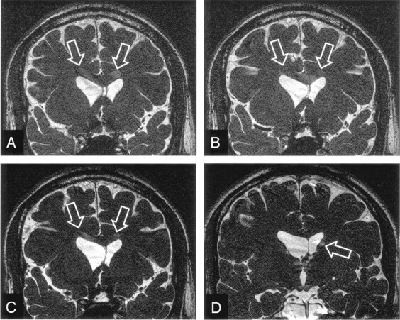
Increased section aliasing artifacts in 3D SSFP imaging on a 33-year male subject. Several inner sections, the 13th (A), 17th (B), and 21st (C) anterior sections in a 84-section volume acquired with a designated flip angle of 70°, are shown to exhibit prominent aliased CSF signals (A–C, arrows) from the lateral ventricles actually located at a posterior region (D). The posterior section also shows evidence of section aliasing from anterior region (D, arrow).
It is seen from Figure 3 that by lowering the designated flip angle, the percentage extent of section aliasing could be reduced; however, this is achieved at the expense of decreased CSF-parenchyma contrast, as is shown in Figure 5, which plots the CSF–white matter contrast. Experimental values again showed good agreement with theoretical predictions. Note that, as one reduces the designated flip angle to reduce section aliasing, contrast between CSF and white matter declines. Figure 6(A–C) demonstrate this situation of trade-off. An inner section (the 8th anterior section in a 36-section volume) exhibits aliased CSF signals from the lateral ventricles when the images were acquired by using a 70° flip angle. By lowering the flip angle to 50° (Fig 6B) and 30° (Fig 6C), the section aliasing artifacts reduce and become invisible, respectively, but the contrast between CSF and the brain parenchyma is lowered, as predicted.
Fig 5.

Contrast between CSF and white matter calculated as a function of the designated flip angle (dotted line), superimposed by experimental values (circles) measured from the images obtained from the healthy subjects recruited in our study. The measurements showed that the CSF-parenchyma contrast reduces as flip angle decreases, in good agreement with theoretical derivations.
Fig 6.

Images acquired from a 23-year-old man healthy subject showing comparison of section aliasing artifacts in 3D SSFP imaging, as a function of the designated flip angle. The 8th anterior section in a 36-section volume acquired with a designated flip angle of 70° (A), exhibits prominent aliased signals from CSF (arrows). By lowering the flip angle to 50° (B) and 30° (C), the section aliasing decreases (arrows) and becomes invisible, respectively. Also note the continuous reduction in the contrast between CSF and brain parenchyma from A to C.
Discussion
The 3D balanced SSFP imaging technique is attractive for MR ventriculocisternography because it is capable of providing submillimeter voxel resolution along all three directions (3, 4, 6). Unfortunately, the current literature is lacks comprehensive documentation on the optimization of imaging parameters in SSFP imaging, especially for neural imaging. Results from our study indicate that the flip angle effect alone is an important factor that presents an obvious trade-off between image contrast and aliasing artifacts in 3D SSFP MR ventriculocisternography. The typical designated flip angle of 70° (1, 3–6), aiming at maximizing fluid signals in SSFP imaging, is shown in our study to cause prominent section aliasing artifacts affecting nearly one-third of the imaging sections. The presence of the artifacts, if superimposed on the disease, could possibly hamper accurate diagnostic interpretation. Therefore, it would be desirable to reduce the extent of aliasing in 3D balanced SSFP imaging, even though the artifacts have not yet led to misleading diagnosis in our institution.
The nature and extent of section aliasing in 3D balanced SSFP imaging is quite different from other 3D techniques. As opposed to signals peaked at a small Ernst angle in nonsteady-state gradient-echo imaging (i.e., aliasing prominent only in some specific imaging sections) (10), signals from CSF in balanced SSFP are comparable in magnitude for a relatively wide range of flip angles (compare Figure 1, the flat region near 70°). Consequently, strong signals in 3D SSFP ventriculocisternography extend continuously outside of the imaging slab, causing section aliasing to affect a large number of contiguous imaging sections. In addition, the use of saturation bands adjacent to the 3D slab is not a desirable solution in balanced SSFP imaging, because the resulting lengthening in TR could lead to severe banding artifacts, making images less useful for clinical diagnosis (1). Similarly, the use of radio-frequency pulse with improved slab profiles designed by using, for example, Shinnar-LeRoux transform (11) is not effective for balanced SSFP imaging, because these improved radio-frequency waveforms are achieved at the expense of relatively long radio-frequency pulse duration (11, 12) that is not suitable for short-TR balanced SSFP imaging.
Conclusion
As shown both theoretically and experimentally in this study, a simple means to reduce the section aliasing artifacts is to use a smaller designated flip angle for SSFP imaging. By choosing a designated flip angle such that the SSFP signals vary more steeply with the actual flip angle (such as 40°; compare Figure 1), the section aliasing artifacts are shown to decrease. In our experience, we found that the designated flip angle of 40° reaches a good compromise between artifacts and contrast, showing nearly 60% reduction in the extent of section aliasing with only about 20% decrease in CSF-parenchyma contrast, as compared with the use of 70° flip angle. We therefore conclude that SSFP imaging at a flip angle of about 40° could serve as an effective method suitable for 3D MR ventriculocisternography in clinical practice.
Footnotes
Supported in part by the National Science Council under grants NSC-92-2218-E-002-017 and NSC-92-2218-E-110-006.
Presented at the 12th annual meeting of the International Society for Magnetic Resonance in Medicine, May 15–21, 2004.
References
- 1.Haacke EM, Wielopolski PA, Tkach JA, Modic MT. Steady-state free precession imaging in the presence of motion: application for improved visualization of the cerebrospinal fluid. Radiology 1990;175:545–552 [DOI] [PubMed] [Google Scholar]
- 2.Naganawa S, Koshikawa T, Fukatsu H, et al. MR cisternography of the cerebellopontine angle: comparison of three-dimensional fast asymmetrical spin-echo and three-dimensional constructive interference in the steady-state sequences. AJNR Am J Neuroradiol 2001;22:1179–1185 [PMC free article] [PubMed] [Google Scholar]
- 3.Schmitz B, Hagen T, Reith W. Three-dimensional true FISP for high-resolution imaging of the whole brain. Eur Radiol 2003;13:1577–1582 [DOI] [PubMed] [Google Scholar]
- 4.Tsuchiya K, Aoki C, Hachiya J. Evaluation of MR cisternography of the cerebellopontine angle using a balanced fast-field-echo sequence: preliminary findings. Eur Radiol 2004;14:239–242 [DOI] [PubMed] [Google Scholar]
- 5.Chung HW, Chen CY, Zimmerman RA, et al. T2-weighted fast MR imaging with true FISP versus HASTE: comparative efficacy in the evaluation of normal fetal brain maturation. AJR Am J Roentgenol 2000;175:1375–1380 [DOI] [PubMed] [Google Scholar]
- 6.Jayakumar PN, Kovoor JM, Srikanth SG, Praharaj SS. 3D steady-state MR cisternography in CSF rhinorrhoea. Acta Radiol 2001;42:582–584 [DOI] [PubMed] [Google Scholar]
- 7.Huang TY, Huang IJ, Chen CY, et al. Are TrueFISP images T2/T1-weighted? Magn Reson Med 2002;48:684–688 [DOI] [PubMed] [Google Scholar]
- 8.Sekihara K. Steady-state magnetizations in rapid NMR imaging using small flip angles and short repetition intervals. IEEE Trans Med Imaging 1987;6:157–164 [DOI] [PubMed] [Google Scholar]
- 9.Joseph PM, Axel L, O’Donnell M. Potential problems with selective pulses in NMR imaging systems. Med Phys 1984;11:772–777 [DOI] [PubMed] [Google Scholar]
- 10.Wilman AH, Riederer SJ. On the cause of increased aliasing in the slice-select direction in 3D contrast-enhanced magnetic resonance angiography. Magn Reson Med 2000;44:336–338 [DOI] [PubMed] [Google Scholar]
- 11.Pauly J, Le Roux P, Hishimura D, Macovski A. Parameter relations for the Shinnar-Le Roux selective excitation pulse design algorithm. IEEE Trans Med Imaging 1991;10:53–65 [DOI] [PubMed] [Google Scholar]
- 12.Shinnar M, Eleff S, Subramanian H, Leigh JS. The synthesis of pulse sequences yielding arbitrary magnetization vectors. Magn Reson Med 1989;12:74–80 [DOI] [PubMed] [Google Scholar]