Abstract
Fluoroscopy is a radiographic procedure for evaluating esophageal disorders such as achalasia, dysphasia and gastroesophageal reflux disease (GERD). It performs dynamic imaging of the swallowing process and provides anatomical detail and a qualitative idea of how well swallowed fluid is transported through the esophagus. In this work, we present a method called mechanics informed fluoroscopy (FluoroMech) that derives patient-specific quantitative information about esophageal function. FluoroMech uses a Convolutional Neural Network to perform segmentation of image sequences generated from the fluoroscopy, and the segmented images become input to a one-dimensional model that predicts the flow rate and pressure distribution in fluid transported through the esophagus. We have extended this model to identify and estimate potential physiomarkers such as esophageal wall stiffness and active relaxation ahead of the peristaltic wave in the esophageal musculature. FluoroMech requires minimal computational time, and hence can potentially be applied clinically in the diagnosis of esophageal disorders.
Keywords: flexible tube, image segmentation, convolutional neural network, one-dimensional flow, esophageal wall stiffness, esophageal active relaxation
1. Introduction
The esophagus is a multi-layered muscular tube that transports food from the pharynx to the stomach with the help of neurally activated peristaltic contractions. Esophageal disorders can cause disruption of the process of swallowing, and a variety of symptoms including dysphagia, chest pain, and heartburn. Some of these disorders are gastroesophageal reflux disease (GERD), achalasia and eosinophilic esophagitis (EoE). The esophageal wall properties and neural activation play a significant role in esophageal transport and are therefore, potentially important physio-markers of esophageal disorders. Hence, understanding the biomechanics of esophageal transport can provide important insights into the nature of these disorders. The mechanics of esophageal transport have been studied extensively using analytical study [3, 17], numerical simulations focused on particular aspects of esophageal transport [7, 16, 31], and fully-resolved models which capture the interaction between a fluid bolus and the esophageal walls [12, 13].
Among the methods for evaluating esophageal disorders are the barium swallow esophagram, video fluoroscopy swallowing exam (VFSE), and high-resolution manometry (HRM). Both the esophagram and VFSE are radiographic tests that examine the dynamic function of the esophagus. In a barium swallow, barium is used as a contrast material to clearly delineate the esophageal lumen on an X-ray. This can reveal structural abnormalities of the esophagus and stomach such as hiatal hernia, diverticula, dilatation, etc. Video fluoroscopy uses the same concept, but creates a real-time X-ray movie of bolus transport. In HRM, a catheter is passed transnasally through the esophagus into the stomach (see Fig. 1(a)). The catheter incorporates pressure sensors along its length that quantify the intraluminal pressure along the length of the esophagus as the patient swallows fluid or food. HRM provides information about the strength and velocity of peristaltic contractions as well as the tone of the upper and lower esophageal sphincters. Barium swallow and VFSE are non-invasive but provide only qualitative information about esophageal transport. On the other hand, HRM is invasive, but provides precise quantitative information about esophageal contractility. In this work, we present a method to partially bridge the gap between these methods. We have developed a method called mechanics informed fluoroscopy (FluoroMech) that can be used along with VFSE to predict the flow rate, pressure and esophagus wall state, thereby providing quantitative information about bolus transport and esophageal contractility.
Figure 1:
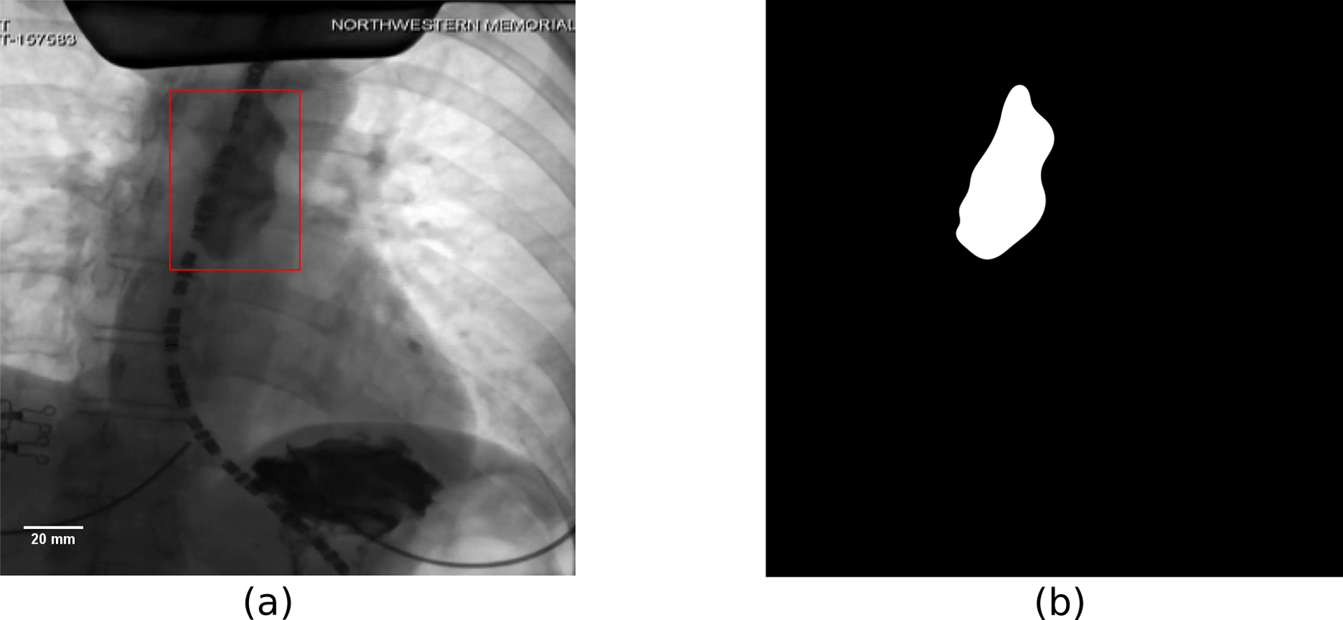
Example of an image from VFSE performed jointly with HRM on a normal subject in supine position. (a) Original esophagram image. The bolus is the dark region inside the red box. The dashed curve is the HRM catheter passing through the esophagus. The pressure sensors in the catheter can be seen as the black dashes which are separated by gaps of 1 cm. The diameter of the catheter is 4.2 mm and is used to define the scale shown in the figure. (b) Label image showing the bolus in white and the remainder as black. The original and label images were used to train the CNN.
Previous studies have used data from fluoroscopy and manometry for the analysis with fluid mechanics [7, 16] and provided important insights into esophageal transport and mechanisms of a variety of disorders. However, a drawback of these techniques is that substantial time and effort is required to manually obtain the shape of the bolus from the fluoroscopy images and then perform an analysis based on that geometry. Since the geometry varies from patient to patient as well as for different swallows in the same patient, this entire analysis has to be repeated for every test sequence. Hence, these methods are not practical for clinical applications. FluoroMech uses deep learning to perform automatic segmentation of image sequences from fluoroscopy. This eliminates the tedious manual process of segmenting the fluoroscopy images, thereby making the process significantly faster and much more convenient. These segmented images delineate the outline of the bolus which then becomes input to a one-dimensional model that predicts the fluid flow rate and pressure. We also present a method to predict the regional stiffness of the esophageal walls and the active relaxation at the locus of the bolus using the pressure predicted from the one-dimensional model and the shape of the bolus. Our analysis requires minimal input from the user and requires minimal computational time. Hence, FluoroMech can be used in clinical applications, particularly to aid in making VFSE a more powerful non-invasive diagnosis tool.
2. Image segmentation of fluoroscopy
The volumetric quantification of fluid inside the esophagus can be approximated from two-dimensional images of the bolus in fluoroscopy. Fig. 1(a) shows an example of a single image from a sequence of images generated from a VFSE of a normal subject performed with the subject in supine position. In general, a single VFSE generates 100 – 500 images depending on the time taken for each swallow sequence to complete. Hence, it is not feasible to manually outline the boundary of the barium bolus repetitively throughout the transport process. Rather, an automated technique is desirable to perform segmentation of the image sequences. There are several methods available in the literature for image segmentation such as thresholding [26], region growing [22], clustering [6], edge detection [27], artificial neural networks [5, 8, 11, 24, 25]. Surveys of the various image segmentation techniques used in medical applications were performed by [24, 28].
2.1. Neural network architecture
In this work, we used a convolutional neural network architecture (CNN) called TernausNet [8] to perform image segmentation. TernausNet is a modified form of the classical UNet [25] which consists of an encoder and decoder path with skip connections that combine feature maps from the encoder and decoder paths leading to precise localization. TernausNet takes advantage of transfer learning by replacing the encoder part of U-Net with VGG11/VGG16 network pretrained on ImageNet dataset, which consists of millions of images. Therefore, the low-level features learned from a huge dataset can be efficiently utilized and the total number of parameters to be learned is reduced significantly. In this work, the encoder part consists of VGG16. The decoder path is similar to that of the original TernausNet with the slight modification of having two sets of Conv 3 × 3 and ReLU at each level instead of one. The full network architecture is shown in Fig. 2. In order to prevent over-fitting, we have also introduced batch normalization after every convolution layer in the decoder section. The whole network consists of 36,319,201 parameters, of which 28,676,001 were pre-trained and 7,643,200 were trained.
Figure 2:
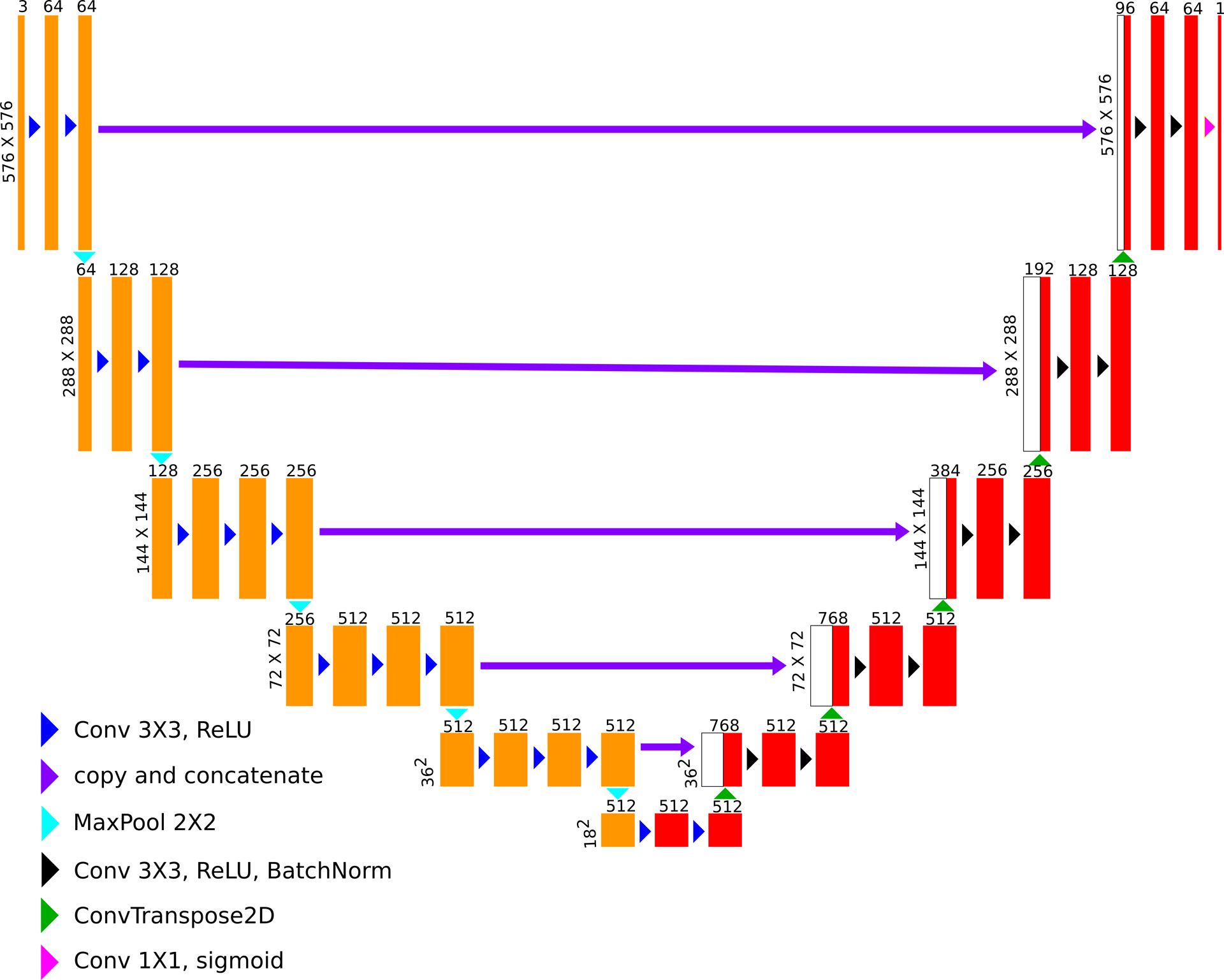
Neural network architecture (based on TernausNet). The feature maps marked in yellow represents the VGG16 encoder pre-trained with the ImageNet dataset. The feature maps in red represent the decoder which is trained using the fluoroscopy images.
2.2. Dataset
To train the CNN, it is necessary to have a dataset of esophagram images that show the bolus at various locations along the length of the esophagus in different shapes and sizes. We used 136 esophagram images collected from a total of 99 different swallows from 14 different subjects that include both normal controls and patients. The sole purpose of the CNN is to identify the bolus from the background, and for that, it does not require to be trained with fluoroscopy images from a large cohort of subjects that include both normal controls and patients with a large variety of esophageal disorders. The 136 images along with augmentations contained enough variability and were large enough to train and validate the CNN to identify the bolus in any fluoroscopy image irrespective of the state of the esophagus. Each of these images has a size of 576×576 pixels. We obtained these images from VFSE done in association with HRM recordings (hence, the presence of the catheter in Fig. 1(a)). These images were manually segmented for labeling as shown in Fig. 1(b). Since the training dataset is very small, it makes sense to take advantage of transfer learning through the pre-trained encoder to prevent over-fitting. In addition to that, we have also implemented various image augmentations such as rotation, height and width shifts, varying brightness, shearing, piecewise affine and scaling. This was done to prevent overfitting due to the lack of a huge dataset and to introduce generalizability into the model. These augmentations were applied randomly to varying extents, the range of which is provided in Table 1.
Table 1:
Details of data augmentations
| Augmentation type | Range | |
|---|---|---|
| Min | Max | |
| Rotation | −10.0o | 10.0o |
| Width shift | −10% | 10% |
| Height shift | −10% | 10% |
| Brightness | 50% | 150% |
| Shear | −5o | 5o |
| Zoom | 80% | 120% |
| Piecewise affine | 0.00 | 0.03 |
2.3. Training and segmentation prediction
The dataset of 136 images was divided into two parts: 112 images for training and 24 images for validation. This is a semantic segmentation problem, wherein each pixel belongs to one of the two classes: 1 for bolus and 0 for the background. We used a sum of binary crossentropy (BCE) and negative Intersection over Union (IOU) loss functions as the total loss (L) defined as follows:
| (1) |
| (2) |
| (3) |
where N is the total number of pixels in the output, yi and are the target binary value and predicted value of the i-th pixel, respectively. The ϵ added in the numerator and denominator of IOU is a small number (= 10−7), which is introduced to calculate IOU over both the classes: bolus and background. To evaluate the performance of the model, the predicted images were converted to their binary forms using various thresholds between 0.5 and 1.0, and IOU were calculated for each of them and then averaged.
The model was trained for 200 epochs with batches of 2 images using Keras, a high-level neural network API [4], which runs on top of TensorFlow [1], to train the network. The training was performed using RMSProp optimization algorithm with a learning rate of 0.001. The Intersection over Union for the validation set obtained at the end of the training was 0.75, which was good enough for our analysis, and show that the trained CNN is generalized to predict on a large variety of fluoroscopy images. The segmented output images were converted to binary form using a threshold of 0.5 for the final output. Some of the image frames for a sequence of images generated from a VFSE and the predicted segmentation of those images after thresholding are shown in Fig. 3(a)–(j).
Figure 3:
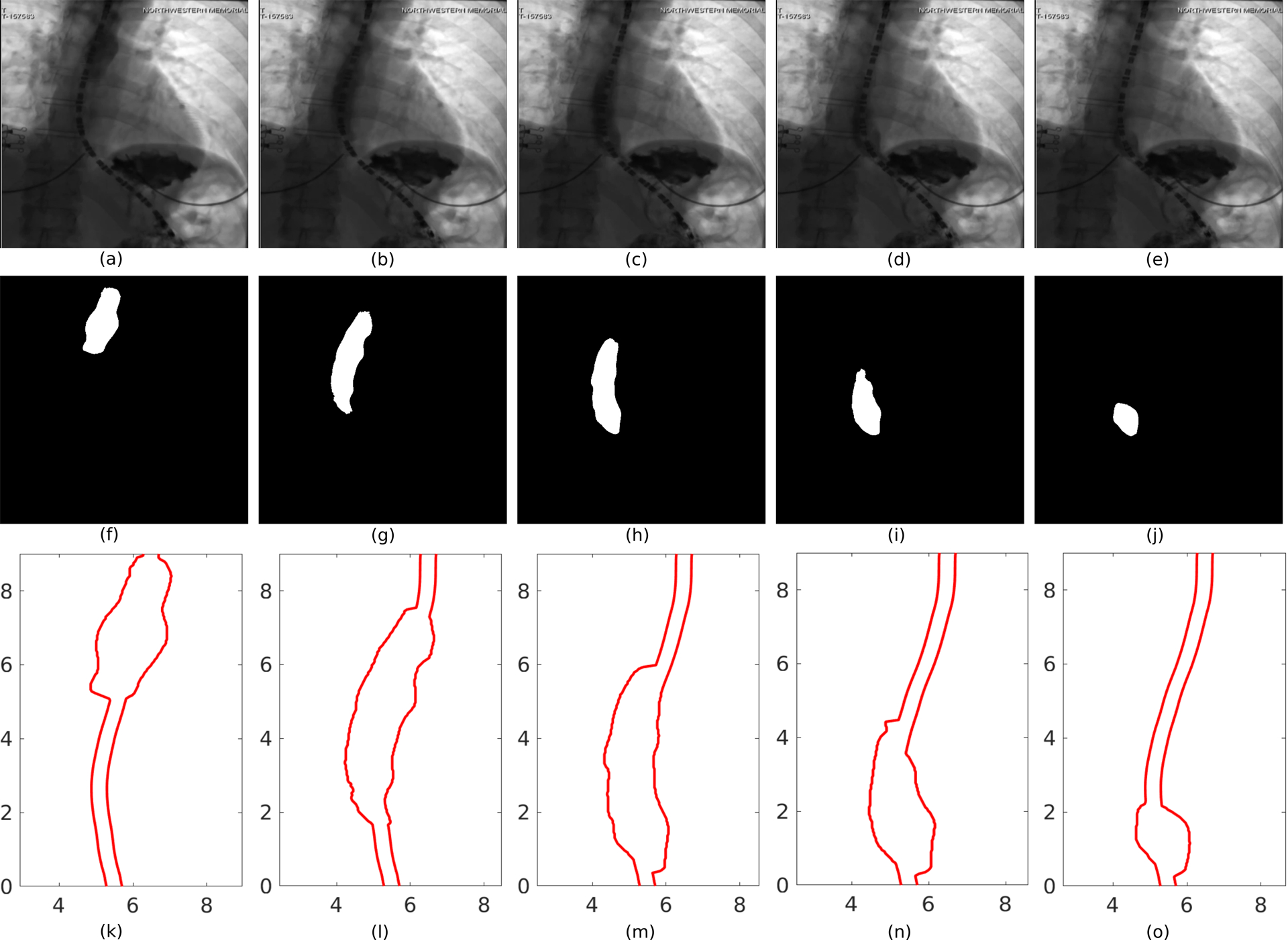
Segmentation of image frames of a VFSE. (a)-(e) Bolus transported from the proximal to the distal end of the esophagus and emptying into the stomach, (f)-(j) corresponding image segmentation, (k)-(o) corresponding outline of the esophageal lumen for analysis.
2.4. Post-processing
The sharp interface between the white and dark regions of the segmented images marks the outline of the bolus. It gives the shape of the inner mucosal surface of the esophagus at the location of the bolus, but no information about regions of esophageal contraction or relaxation. The diameter of the catheter (dashed curve in Fig. 1(a)) is approximately 4.2 mm. We used this as the scale for mapping the pixel data to length. In some image frames, the relaxed diameter of the esophagus can be identified at some locations along the length due to remnant barium lining the lumen. To simplify our analysis, we assumed that this diameter is the relaxed diameter of the esophagus throughout its length, although, in reality, the esophagus may be collapsed or the inner diameter may vary along the length [30]. Fig. 3(k–o) displays the shape of the esophageal lumen which is used for the analysis described in the next section. The semantic segmentation performed on the esophagram images basically assigns each pixel to one of the two classes: bolus (white region) and the remainder (dark region). The resulting segmented images do not show a smooth boundary for the bolus and is irregular at the scale of the resolution of the original image. Also, since the segmentation is done on each of the images separately, the continuity between the images at consecutive time frames is broken. Therefore, the pixel data were smoothed both in space and time without the loss of bolus geometry detail. The smoothing is performed by Gaussian weighted moving average over a window of 10 and 30 points in space and time, respectively.
3. Mathematical formulation
3.1. Governing equations
An important aspect of patient-specific analysis of esophageal transport is obtaining the flow rate and pressure field inside the esophagus with reasonable accuracy using limited computational resources and time. To that extent, we have used the formulation of a one-dimensional flow through a flexible tube [2, 10, 18, 21] in FluoroMech to model the transport process. The mass and momentum conservation equations in one-dimension are follows:
| (4) |
| (5) |
where ρ is the density of the fluid, μ is viscosity of the fluid, A is the cross-sectional area of the esophagus, Q is the flow rate, P is the pressure, t is the time and x is the spatial coordinate along the length of the esophagus with its positive direction defined as moving from the pharynx to the stomach. In our analysis, we only consider VFSE performed on subjects in supine position. Therefore, we do not have a gravity term in the momentum equation. To apply our analysis on VFSE performed on subjects in upright position, it is necessary to introduce a gravity term in Eq. 5. The flow rate, Q(x, t) is defined as follows:
| (6) |
where um is the mean velocity of the fluid across a cross-section. The factor 4/3 in Eq. 5 comes from assuming a parabolic velocity profile perpendicular to the direction of flow.
Eqs. 4 and 5 are non-dimensionalized to the following form:
| (7) |
| (8) |
where, χ = x/L, α = A/Ao, p = P/(ρc2), q = Q/(Aoc), τ = ct/L and ψ = 8πμL/(ρcAo). Here L is the length of the esophagus visible in the esophagram, Ao is the relaxed cross-sectional area of the esophageal lumen, and c is the average velocity of the center of the bolus. The center of the bolus (xb) was located at each time instant using the following relation:
| (9) |
In this instance, L = 11.86 cm, Ao = 59.04 mm2 and c = 3.5 cm/s. We assumed the properties of water (at STP) for the swallowed fluid, i.e ρ = 1000 kg/m3, μ = 8.9 × 10⁻⁴ Pa. s. Using these values, we get ψ = 2.413. The total time required for bolus to be transported through the esophagus was 5.1 seconds.
3.2. Initial and Boundary Conditions
The boundary conditions imposed on the FluoroMech model depend on the behavior of the upper and lower esophageal sphincters at the proximal and distal ends of the esophagus, respectively. The upper esophageal sphincter (UES) is located at the distal end of the pharynx and remains closed [15] in order to prevent the entry of air into the esophagus during breathing and reflux of the bolus from the esophagus back into the pharynx [19]. It relaxes for 0.32 – 0.5 seconds [9] in order to allow the bolus to enter the esophagus. The esophageal pressure topography in Fig. 4 illustrates this behavior of the UES. The horizontal high-pressure zone at the top marks the location of the UES, which remains contracted on the HRM catheter. It opens only to allow the bolus to enter the esophagus, which is visible as the break in the continuous high-pressure zone due to relaxation. The oblique band of pressure represents the peristaltic contraction which propels the bolus along the esophagus. Hence, the location of the proximal end of the bolus can be roughly identified to be just distal to the contraction. The lower esophageal sphincter (LES) is marked by the lower horizontal high-pressure zone. There is a break in high pressure in this location soon after the bolus enters the esophagus. This represents the relaxation of the LES to facilitate the bolus emptying into the stomach. In our analysis, the bolus is already inside the esophagus, and so the UES is closed. Hence, there is no flow at the entry, i.e. q(χ = 0, τ) = 0. Additionally, we assume that there was no initial flow inside the esophagus, i.e. q(χ, τ = 0) = 0. Since Eq. 8, contains a first-order derivative form for pressure, we have specified a reference value for the pressure (p) at the distal end equal to the intragastric pressure which in this scenario is 21.4 mmHg. This is a reasonable assumption because the LES relaxes immediately at the beginning of a swallow, and the distal end of the esophagus experiences the intragastric pressure.
Figure 4:
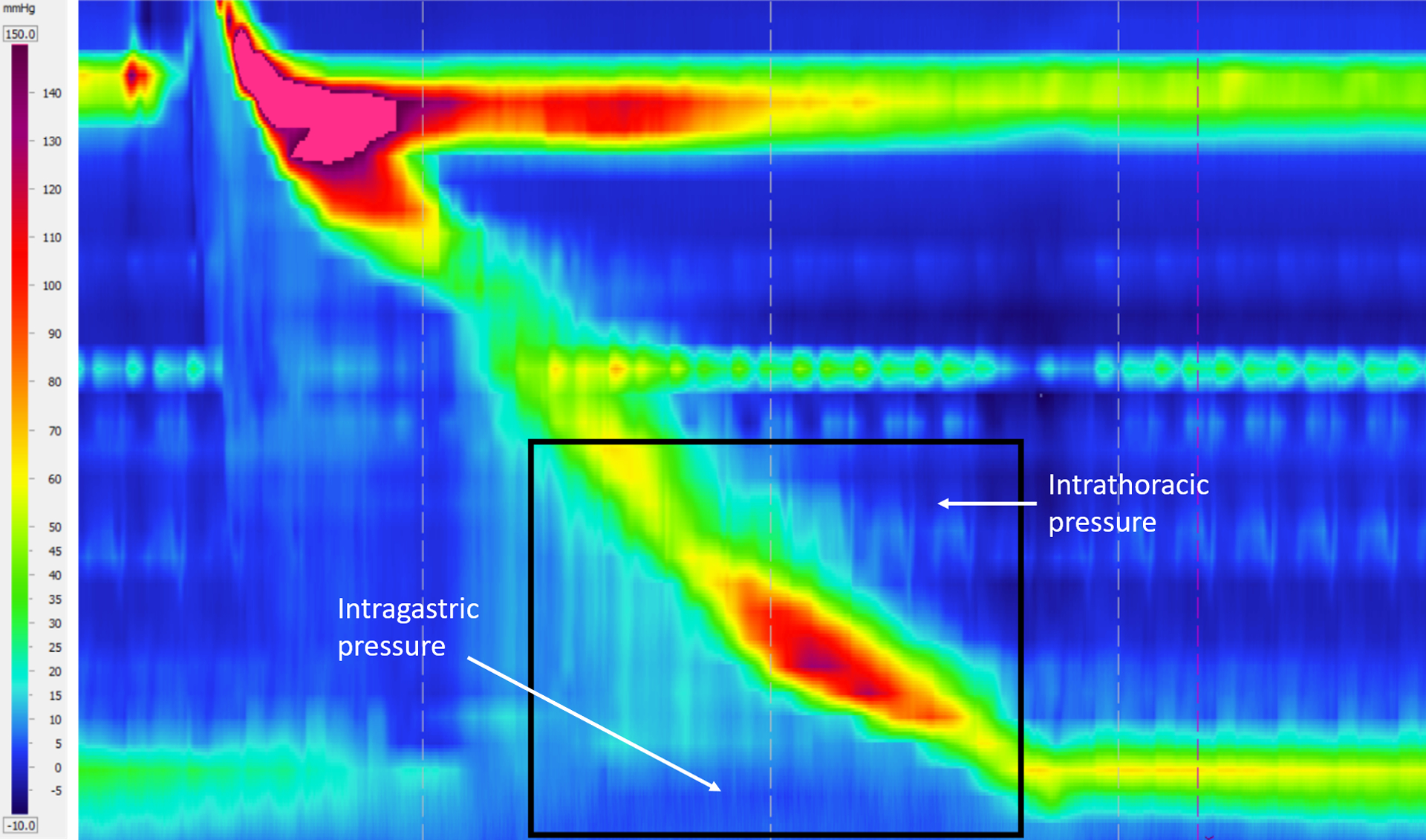
Esophageal pressure topography generated from pressure sensors on the HRM catheter. The horizontal axis represents time, and the vertical axis represents the length along the esophagus. The rectangular box shows the location of the EPT corresponding to the fluoroscopy. The horizontal high-pressure band (in red) at the top and bottom show the UES and LES tone, respectively. The peristaltic contraction is shown by the oblique high-pressure band that travels from the UES to the LES to push the bolus through the esophagus.
3.3. Enforcing volume conservation
The fluoroscopy images show only a two-dimensional projection of the esophagus. Assuming a circular cross-section, we calculated the total volume of fluid inside the esophagus (as shown in Fig. 5a). The volume V is non-dimensionalized using the product of the non-distended cross-sectional area and the length of the esophagus, i.e. V* = V/(AoL). In terms of the volume of fluid inside the esophagus, the bolus transport is categorized into two parts: pure transport (no flow at χ = 1) and emptying. From the VFSE image sequences we have observed that the transport without emptying occurs until τ = 0.5, and then the volume within the esophagus decreases continuously. Since we have no flow boundary condition at the proximal end, the volume within the esophagus can never exceed the total volume at τ = 0. However, during pure transport at τ < 0.5, there are some fluctuations in the calculated volume within the esophagus. This can be attributed to our calculation of volume assuming the esophagus is always perfectly circular in cross-section. Since we have no information about the actual shape of the cross-section at τ = 0, we can neither use the calculated volume at τ = 0, nor the maximum calculated volume during the whole transport in order to enforce volume conservation.
Figure 5:
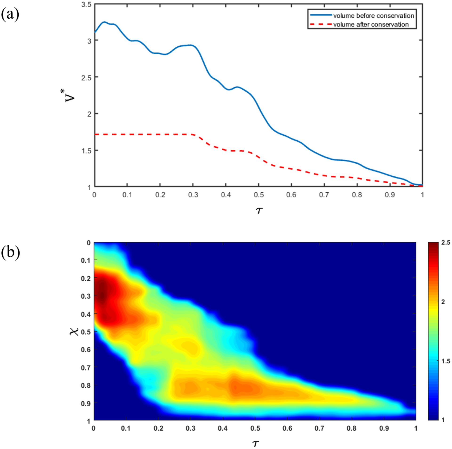
Enforcing volume conservation. (a) Non-dimensional volume (V ^ *) inside the esophagus. The blue line shows the total volume of fluid inside the esophagus calculated assuming a bolus with a circular cross-section with diameter obtained from the bolus width observed in the segmented images. The red dashed line shows the total volume inside the esophagus after volume correction using the fact that the swallowed bolus is 5 mL; (b) Ratio of the initially assumed circular cross-sectional area (A) and the corrected cross-sectional area (A ^ *). The oblique band of high cross-sectional area correction shows that the correction is performed only inside the bolus, and not in the relaxed parts of the esophagus where .
In reality, the shape of the esophagus cross-section is approximately elliptical [30], with the major axis being observed in the fluoroscopy images. Additionally, due contact with the surrounding organs, the esophagus cross-section might take irregular shapes. Hence, the volume of the bolus calculated assuming a perfectly circular cross-section does not match the volume of fluid swallowed during every test, i.e. Vo = 5 mL. Therefore, it is necessary to perform a volume correction so that our analysis uses the calculated volume that is consistent with the actual swallowed volume. Since fluoroscopy images do not contain any information about the three-dimensional geometry of the bolus, the only alternative is to perform a volume correction using the two-dimensional shape of the bolus. This was done by scaling the initially assumed circular cross-sectional areas as shown below:
| (10) |
where A* is the scaled cross-sectional area to conserve volume and β is the scaling factor. This method scales the cross-section of the esophagus at the bolus location only and does not change the relaxed sections.
We enforced a constant volume during pure transport (as shown by the red dashed line in Fig. 5a) until τ = 0.5. However, during emptying (τ > 0.5), the volume within the esophagus begins to decrease, so, we cannot scale the volume using a reference value. Therefore, the volume is scaled using β calculated at the beginning of the emptying process (τ = 0.5). In general, the shape of the esophageal cross-section varies along its length, and the shape it takes when distended depends upon the material properties of the wall. The β calculated at each time step during pure transport gives a measure of the shape of the cross-section. As the bolus is transported through the esophagus, the β takes on different values, thereby estimating the shape in finite segments along the length. At the beginning of emptying, the distal end of the bolus has already reached the end of the esophagus. After this, the length of the bolus progressively decreases without moving any forward. Therefore, the β calculated at τ = 0.5 is a reasonable scaling for volume during emptying.
During emptying, the volume within the esophagus must decrease. Therefore, if at any instant, the calculated volume inside the bolus is greater than it was in the previous time instant, we force the volume at the current instant to be equal to that of the previous instant. The effect of the bolus volume correction is shown in Fig. 5a. The ratio of the initially assumed circular cross-sectional area (A) and the scaled cross-sectional area (A*) is shown in Fig. 5b. We see that the cross-sectional area scaling occurs only at the location of the bolus since A/A* remains equal to 1 for the remainder of the esophagus. Comparing Fig. 5a and 5b, we see that the maximum scaling occurs before τ = 0.2 when the difference between the reference volume and the calculated volume is maximal.
It has been observed in fluoroscopy studies that sometimes the bolus gets split into two segments during transport in the upper esophagus. In such a scenario, our analysis can be applicable with some modifications. The two segments of the bolus have to be treated independently, and volume correction needs to be done separately using the reference volumes of the corresponding segments calculated at the instant when the bolus completely splits. The proximal segment continues to be in a state of pure transport, and the distal segment moves on from a state of pure transport to emptying. Although this method works in principle, the implementation is significantly involved and is beyond the scope of this paper.
3.4. Numerical solution
Using the cross-sectional areas α obtained after enforcing volume conservation, we solved for q and p in Eqs. 7 and 8 using the finite volume method. The flow rate (q) was calculated by solving Eq. 7. A staggered grid was used to discretize the domain as shown in Fig. 6. The flow rate q was calculated at the cell boundaries and pressure p was calculated at the cell centers. The cross-sectional area α was known for both the cell boundaries and centers. The quantities specified at the cell centers have subscripts in upper case, and those at the cell boundaries in lower case. The superscript o represents the value of a quantity in the previous time instant. Eq. 7 was solved using a fully-implicit method with the following discretized form:
| (11) |
where, N is the total number of cells, i, I = 2,3, …, N, (N + 1). Using the calculated values of q and the known values of α, we calculated the values of p at the cell centers using the following discretized form:
| (12) |
where i, I = 1,2, …, (N − 1). In this simulation, the total number of time steps and the total number of cells used were 510 and 171, respectively. Using these values, Δτ and Δχ was calculated as 0.003 and 0.006, respectively. The above mentioned numerical solution was implemented using MATLAB ver. R2018b.
Figure 6:

Staggered meshing of the domain. The cell boundaries and centers are shown in red and green, respectively.
3.5. Pressure variation with the shape and speed of the bolus
The intrabolus pressure during pure transport (before emptying) can be used to calculate the esophageal wall stiffness and active relaxation. Therefore, it is necessary to identify and estimate the factors that lead to pressure variations. The flow rate can be calculated by integrating Eq. 7 with respect to χ as follows:
| (13) |
where the cross-sectional area α is decomposed into the non-distended cross-section area (which is equal to 1 in non-dimensional form) and the extra volume present only inside the bolus (α′). Vχ is the volume inside the bolus calculated by integrating α′ from 0 to χ. The variation of Vχ is shown in Fig. 7, where bi and bf represent the location of the proximal and distal end of the bolus, respectively. Since the total volume Vo is conserved within the esophagus prior to the start of emptying, Vχ = 0 for χ < bi and Vχ = Vo for χ > bf. Therefore, using Eq. 13, we get q = 0 for χ < bi and χ > bf.
Figure 7:
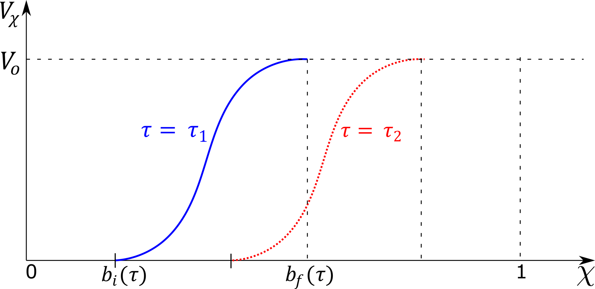
Volume inside the esophagus from 0 up to χ. The blue line shows the volume distribution at time instant τ1, and the red dotted line shows the same as the bolus has progressed in time at τ2. Before the beginning of the bolus bi(τ), there is no fluid inside the esophagus, and the volume is 0. The volume inside the esophagus rises from bi(τ) to the total volume swallowed (Vo = 5 mL) at the end of the bolus bf(τ).
The effect of fluid viscosity is captured by the term in Eq. 8. For a fluid with viscosity similar to water, we have observed that the viscous term is negligible compared to the other terms of Eq. 8. Therefore, we assume the flow to be inviscid and with a flat velocity profile, and write Eq. 8 as follows:
| (14) |
On integrating Eq. 14 with respect to χ from the distal end and using Eq. 13, we get
| (15) |
where the subscript χ indicates the location at which each of the quantities are calculated, and p1, q1 and α1 are the pressure, flow rate and cross-sectional area at χ = 1, respectively. Before emptying begins, q1 = 0 so, the second term of Eq. 15 becomes equal to 0. Since q = 0 for χ < bi and χ > bf, Eq. 14 implies ∂p/∂χ = 0 at these points. Therefore, p = p1 for all χ > bf and p = pi for all χ < bi wherein pi is the pressure at χ = bi. Our results showed that the maximum and minimum values of p are observed at χ = bi, so pi was used as the upper and lower bound of the pressure variation for each time step. At χ = bi, Vχ = 0 so, the third term of Eq. 15 becomes equal to 0. On applying these arguments to Eq. 15, we get
| (16) |
We define an average estimate of the bulk velocity of the bolus, ub for every time instant as follows
| (17) |
where, Lb = bf − bi, is the length of the bolus at each instant of time. Using Eq. 16 and 17, we get
| (18) |
From Eq. 18, we see that the pressure variation between its maximum and minimum can be attributed to the variation of the bulk velocity of the bolus and the change in length of the bolus during transport through the esophagus.
3.6. Estimating the stiffness and active relaxation of esophageal wall
As reported in [14], the fluid pressure developed within the esophagus is directly proportional to the cross-sectional area of the esophageal lumen. Hence, the pressure can be estimated using a tube-law of the form:
| (19) |
where k is the stiffness of the esophageal wall, θ is the active relaxation factor and po is the intrathoracic pressure. Note that k in Eq. 19 is an average estimate of the esophageal stiffness and assumed to be constant along the length of the esophagus. The variation of the bolus shape along the esophagus length is due the variation of θ. If there is relaxation then θ > 1, which effectively reduces the overall pressure developed inside the bolus. The schematic diagram in Fig. 8a shows the localized nature of active relaxation that leads to the formation of an ellipsoidal bolus. Without localized active relaxation, the shape of the bolus would typically be as shown in Fig. 8b. In localized active relaxation as shown in Fig. 8a, θ > 1 inside the bolus and θ = 1 distal to the bolus. The difference between the total pressure inside the bolus and distal to the bolus using Eq. 19, leads to the following form for θ after some mathematical manipulations:
| (20) |
where Δp is the pressure difference between the fluid inside the bolus and distal to the bolus, and α and α1 are the cross-sectional areas inside the bolus and distal to the bolus, respectively. Fig. 9 shows the variation of cross-sectional area in a typical bolus transport. In the above equation, α1 > 1, and due to negligible viscous losses, Δp << k. With these assumptions, the active relaxation in Eq, 20 can be approximated without significant errors as follows:
| (21) |
Sometimes it might be difficult to visualize the esophageal lumen distal to the bolus in fluoroscopy images. In such scenarios, it is impossible to accurately calculate active relaxation using this formulation. Since the minimum value of α1 is 1, Eq. 21 can be used to set bounds on the magnitude of θ as follows:
| (22) |
A simple mathematical manipulation of Eq. 19 gives the following relation:
| (23) |
Since α, θ > 1 and θ > α, the above equation leads to the following inequality:
| (24) |
The left-hand side of the above equation represents the effective stiffness of the esophageal walls with the presence of active relaxation. The right-hand side represents the lower bound of this effective stiffness. The esophageal stiffness experienced by the bolus is lower than the actual stiffness of esophagus wall due to active relaxation. Therefore, the lower bound of k/θ provides an estimate of the in-vivo stiffness of the esophageal walls at the location of the bolus.
Figure 8:

Effect of active relaxation on the shape of the bolus. (a) Bolus shape with active relaxation in a finite segment distal to the contraction. A prominent bulge is formed in the presence of localized active relaxation; (b) Bolus shape without localized active relaxation. Typically, there is no prominent bulge in the absence of localized active relaxation.
Figure 9:
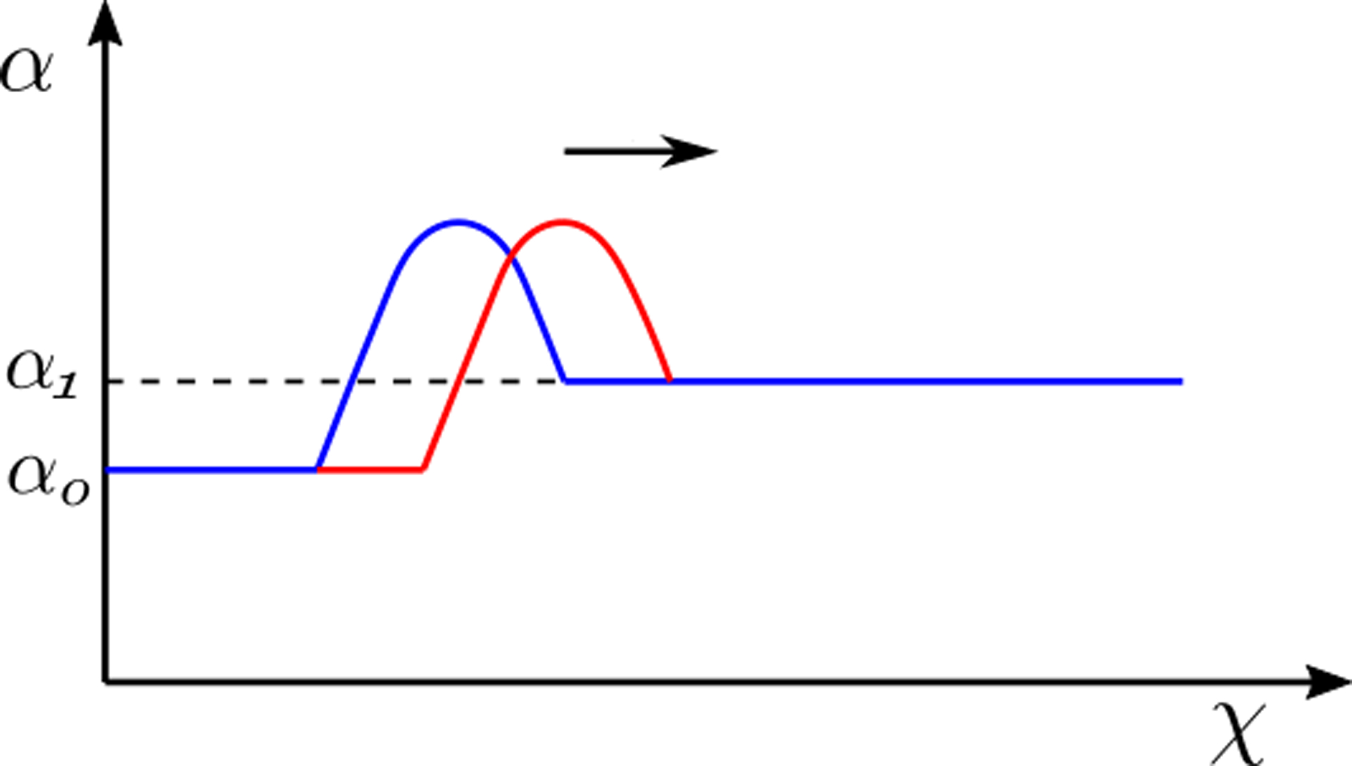
The variation of cross-sectional area shows the bolus moving in the positive χ direction. The transition from blue to the red line shows the movement of the bolus with time (also indicated by the arrow). The bulge at the bolus is due to localized active relaxation. The cross-sectional area distal to the localized bulge is α1, and this part of the esophagus does not experience active relaxation.
4. Results and Discussions
The variation of flow rate and pressure with non-dimensional time and distance along the length of the esophagus is shown in Fig. 10 and 11, respectively. There is no flow at χ = 1 for τ < 0.5, which indicates pure transport without emptying. The flow rate is non-zero only at the location of the bolus. This matches our observation from the fluoroscopy where the bolus is transported without emptying into the stomach. The variations of area with χ and τ lead to fluctuations in pressure (see Fig. 11). As we stated in Section 3.5, we observe in Fig. 11 that the maximum pressure variations can be estimated from the pressure at the proximal end of the bolus. According to Eq. 18, these fluctuations in pressure is estimated from the variation of the bulk speed ub and length Lb of the bolus as shown in Figs. 12a and 12b, respectively. Although p is calculated over the whole domain, the fluid pressure within the bolus is the most accurate description of the actual transport process. This is because the VFSE provides information only about the shape of the bolus. Therefore, we have ignored the calculated pressure proximal to the bolus and replaced with a reference value of zero. Additionally, the peristaltic contraction at the proximal end of the bolus, where the diameter is significantly less, cannot be observed in the fluoroscopy, and is fully occluded most of the time, thereby dividing the fluid domain into two parts. Our FluoroMech model does not incorporate this contraction zone, and instead treat this zone the same as the remainder of the non-bolus domain. Consequently, we do not see a high-pressure zone at the proximal end of the bolus as seen in the Fig. 4. The calculated fluid pressure is the sum of the contributions from the static and dynamic fluid pressures inside the bolus. In this particular scenario, the static pressure is the intragastric pressure specified as a boundary condition at the distal end of the esophagus and is equal to 21.4 mmHg. The static pressure is independent of the flow and remains constant throughout the fluid domain. On the other hand, the dynamic pressure depends only on the fluid flow and is shown as the pressure variations in Fig. 11. From the magnitude of the fluid pressure variations, we see that the dynamic pressure is 2 orders of magnitude smaller than the static pressure. The total pressure inside the bolus is therefore mainly due to the static pressure. The difference between the static pressure inside the bolus and the intrathoracic pressure (8 – 12 mmHg in this case) is balanced by the stresses developed in the esophagus walls due to elastic deformation. The dynamic pressure in the bolus accelerates or decelerates the bolus fluid and balances the viscous drag on the fluid at the esophagus walls. The low values of dynamic pressure compared to the static pressure indicate that the effect of viscosity and fluid acceleration/deceleration on the total fluid pressure in this case is significantly lower compared to the effect of elastic deformation of the esophagus walls in pressurizing the bolus fluid. The manometer readings of fluid pressure inside the bolus mainly represent the static pressure, and in this case, the measured intrabolus pressure lies between 20 – 25 mmHg. The dynamic pressure variations are too small to be accurately measured by manometry, and so cannot be validated with manometry data. The magnitude of pressure from manometry at the contraction is 50–110 mmHg (shown in Fig. 4). Therefore, the contraction pressure is roughly 3 orders of magnitude greater than the dynamic fluid pressure predicted by FluoroMech.
Figure 10:
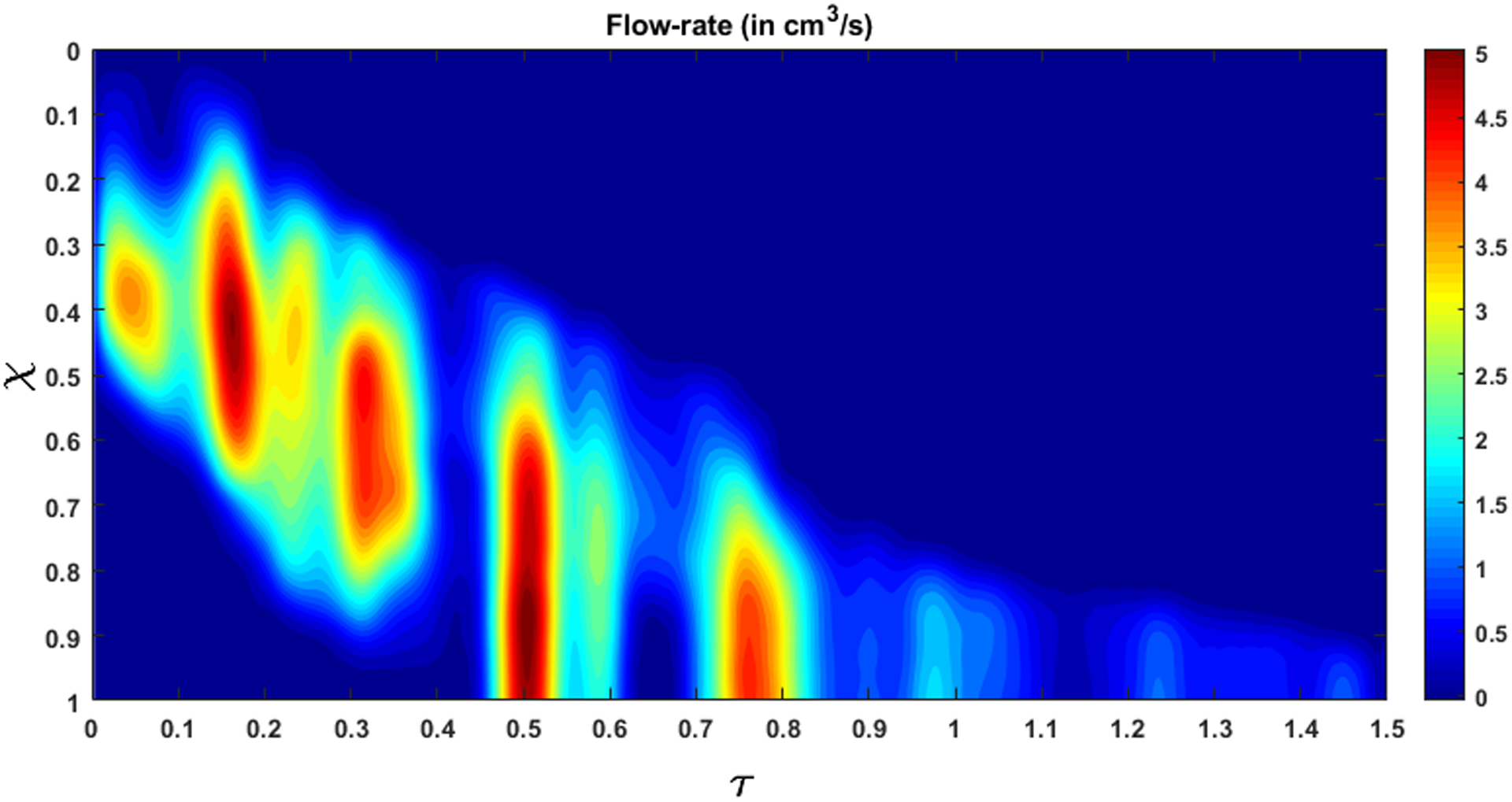
Flow rate within the esophagus. The high flow rate at τ = 0.5 marks the start of emptying.
Figure 11:
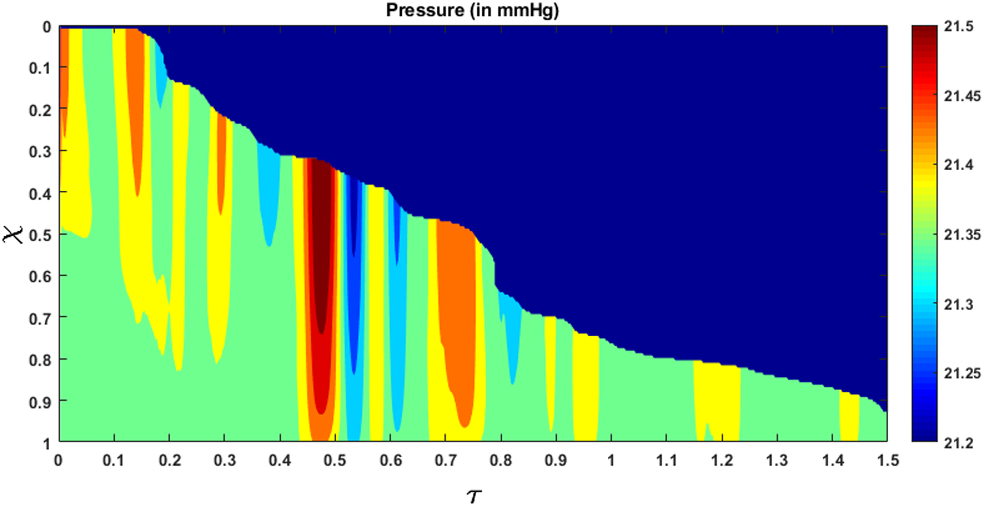
Fluid pressure within the esophagus. The high-pressure gradient near τ = 0.5 shows the LES requires a high pressure gradient to allow fluid to pass through it. The dynamic pressure variations are significantly small compared to the static pressure inside the esophagus.
Figure 12:
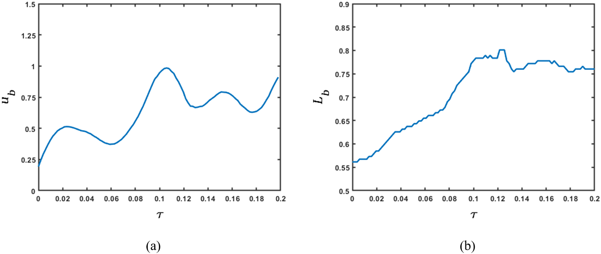
Variation of bolus speed and length before emptying. (a) Bulk speed of the bolus; (b) Length of the bolus. The rate of change of the product of bulk bolus speed and length of the bolus with respect to time quantifies the dynamic pressure variations shown in the previous figure. The variation of bulk bolus speed and its length provide physical intuition of the sources of pressure fluctuations.
Emptying begins at τ = 0.5, which corresponds to q > 0 at χ = 1. This continues until all fluid is emptied into the stomach. From Fig. 10 and 11 we see that during emptying, a high flow rate corresponds to a high intrabolus pressure. In our model, the reference intragastric pressure is specified at χ = 1, so, a high flow rate at χ = 1 requires a higher pressure to be developed inside the esophagus to drive the fluid out. This high pressure inside the bolus indicates the presence of the LES and shows how it behaves differently from the remainder of the esophagus. During normal esophageal transport, the walls distend to accommodate the incoming bolus, and contract back to their relaxed state once the bolus has passed. However, the LES does not distend like the rest of the esophagus, hence a greater pressure inside the bolus is required for the fluid to traverse it.
It is difficult to identify the sources of the dynamic pressure fluctuations as shown in Fig. 11 from the two-dimensional fluoroscopy study. Although our analysis is based on VFSE performed with the subject in supine position, internally the esophagus is never fully horizontal and might have many undulations with varying extents. These undulations can be thought of as small hills and valleys along the length of the esophagus. When the bolus moves up an undulation, it slows down locally and when it moves down an undulation, it locally accelerates. These local acceleration and deceleration lead to fluctuations in the calculated pressure. The esophagus might deform as well due to contact with surrounding organs, which in turn vary with time due to the heart beating, vasculature pulsating, respiration, and overall body movement leading to variations in cross-sectional areas and consequently the pressure.
The esophageal wall stiffness and active relaxation predicted by the FluoroMech model depends on the cross-sectional area only at the bolus. The variation of cross-sectional area during pure transport is shown in Fig. 13. In this figure, we see that the bolus cross-sectional area varies from 2 to 3.5. As described in Section 3.6, our model predicts the minimum stiffness of the esophageal walls which occurs at location of the bolus. The wall stiffness at the bolus is smaller than the rest of the esophagus due to active relaxation. Additionally, the cross-sectional areas are known most accurately at the bolus since that is the only part of the esophagus observed in fluoroscopy. Therefore, in order to calculate stiffness and active relaxation, we consider cross-sectional areas inside the bolus only as indicated by the two horizontal white dashed lines in Fig. 13. The intrathoracic pressure po can also be observed from the EPT in Fig. 4 as the pressure readings proximal to the peristaltic contraction. In this case, the intrathoracic pressure is approximately 8 – 12 mmHg. Using the pressure predicted by our model, and intrathoracic pressure observed from EPT, we calculated the lower bound of esophageal stiffness according to Eq. 24. This estimate of stiffness refers to lowest stiffness that the bolus encounters and captures the effect of active relaxation. Fig. 14 shows the variation of the minimum value of k/θ along the length of the esophagus lying between the white dash lines in Fig. 13. These values of stiffness correspond to the maximum cross-sectional area at any point along the length of the esophagus. In this plot, we have considered the mean of the range of values for intrathoracic pressure, i.e. 10 mmHg. The plot shows the variation of esophageal wall stiffness to be approximately 4.5 – 12.0 mmHg. On comparing Figs. 13 and 14, we see that the minimum stiffness correspond to the maximum cross-sectional areas and vice-versa, which is consistent with the tube-law in Eq. 19. It should be noted that the values of the calculated stiffness have a contribution from the surrounding organs as well. Some locations of the esophagus experience indentations from surrounding organs, and that appears in form of a prediction of relatively high stiffness. Since the stiffness is predicted using fluid pressure, there is no way to distinguish the effect of the surrounding organs from the actual stiffness of the esophagus walls. In Fig. 14 we see that the stiffness values are higher towards the two ends of the x-axis. At the left end, the peristaltic contraction collapses the esophagus, and therefore, our model captures this behavior by predicting a higher stiffness near this region. At the right end, the LES does not distend like the rest of the esophagus. This behavior is manifested through a higher predicted stiffness at the right end. Therefore, we hypothesize that the lower values of predicted stiffness are closer to reality.
Figure 13:
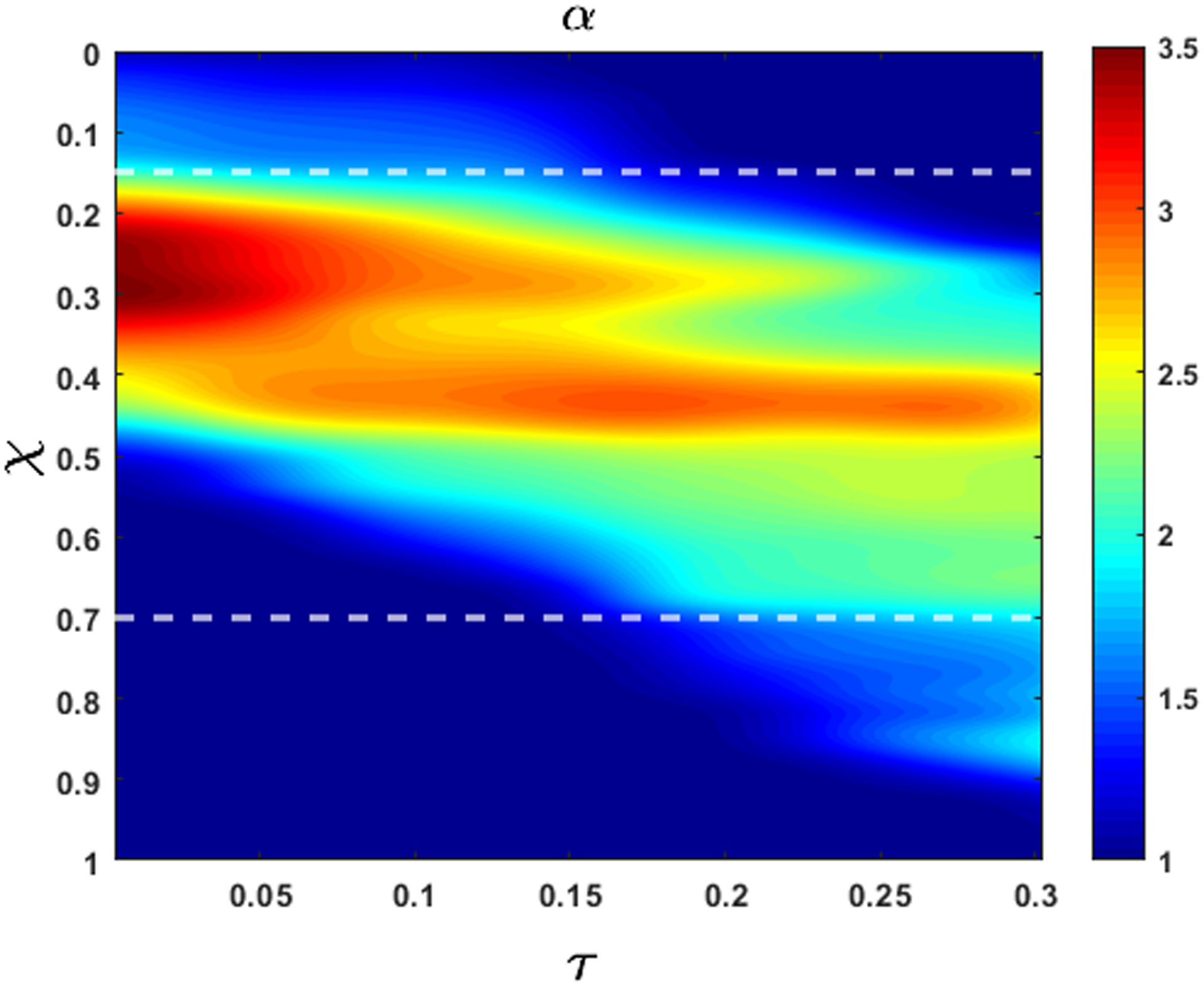
Variation of non-dimensional cross-sectional area with χ and τ during bolus transport without emptying. At τ = 1, α is higher but the bolus has a shorter length. Towards the end of the transport, the bolus elongates but α decreases due to conserved volume during pure transport. The white horizontal dashed lines (at χ = 0.15 and 0.7) mark the length of the esophagus that displays a prominent bolus that can be used to estimate stiffness and active relaxation of the esophageal walls.
Figure 14:
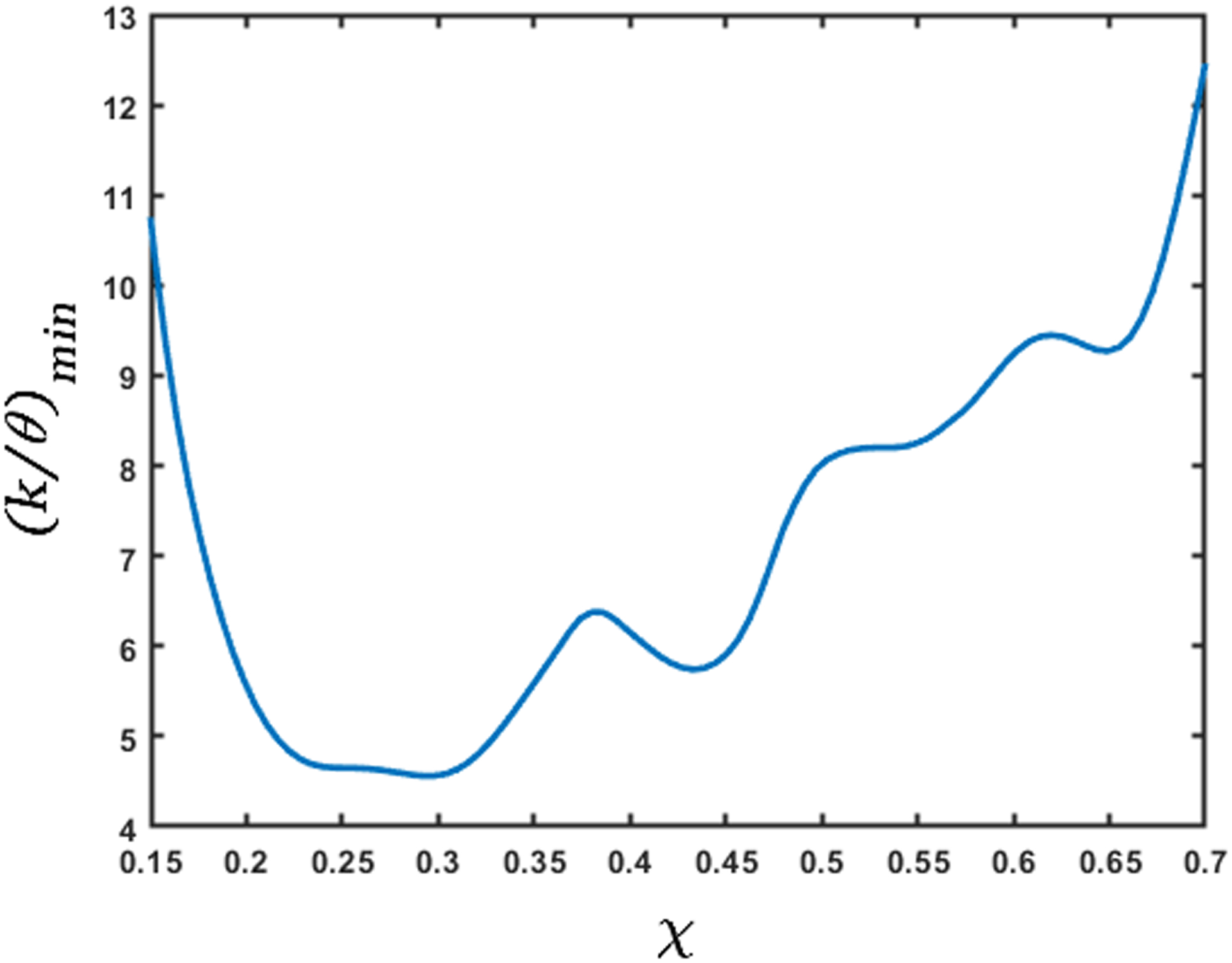
Variation of minimum stiffness (in mmHg) along the length of the esophagus. The x-axis represents the length of the esophagus marked by the dashed horizontal lines in Fig. 13. This measure of stiffness incorporates the effect of active relaxation; therefore, its low values correspond to the high values of cross-sectional areas. The predicted high stiffness at χ = 0.15 and 0.7 is due to the influence of the peristaltic contraction and the LES, respectively.
The in-vivo mechanical properties of human esophagus are reported in [14, 20, 23]. In these studies, a probe with a balloon/EndoFLIP (endolumenal functional lumen imaging probe) was inserted into the esophagus and the balloon/EndoFLIP was filled with water to distend the esophagus. The sensors in the probe measure the cross-sectional areas and pressure inside the esophagus. [20] reported the data of 13 healthy subjects (9 male; age range, 20–27 years), [23] reported data of 11 healthy subjects (5 male; age range, 22–39 years), and [14] reported data of 15 healthy subjects (6 male; age range, 21–68 years). These studies show a linear relationship between pressure and cross-sectional area, and were the motivation for the use of a linear tube-law in Eq. 19. The slopes of their reported plots give an estimate of the quantity Ao/K, where Ao is the relaxed cross-sectional area of the esophagus, and K is the stiffness of the esophagus walls. The Ao/K from [20] and [14] were approximately 11.6 mm2/mmHg and 9.1 mm2/mmHg, respectively. [23] reported the relation between pressure and cross-sectional areas at different regions of the esophagus. The Ao/K in these regions lies in the range 9.5 – 11.5 mm2/mmHg. Using the relaxed cross-sectional area in our analysis, we calculated Ao/K to be 4.9 – 13.1 mm2/mmHg for the subject analyzed. The relaxed cross-sectional area of the esophagus is reported in [30] as 7 − 59mm2. Using this range for cross-sectional areas, the stiffness from [20], [23], and [14] results to 0.6 – 5.0 mmHg, 0.6 – 6.2 mmHg, and 0.8 – 6.5 mmHg, respectively. Therefore, the stiffness of the esophagus of the subject in our analysis is of the same order and close to the range of values reported in literature. An accurate measure of the intrathoracic pressure would increase our accuracy for prediction of esophageal stiffness.
Fig. 15 shows the variation of the maximum active relaxation along the length of the esophagus lying between the white dashed lines in Fig. 13 according to Eq. 21. Since it is difficult to visualize the esophagus lumen distal to the bolus in the fluoroscopy images used for this paper, we assume α1 = 1, which correspond to the upper bound of active relaxation according to Eq. 22. We see that the maximum value of the active relaxation lies between 2 and 3.5. On comparing Figs. 14 and 15, we observe that the maximum relaxation occurs at the locations of minimum stiffness.
Figure 15:
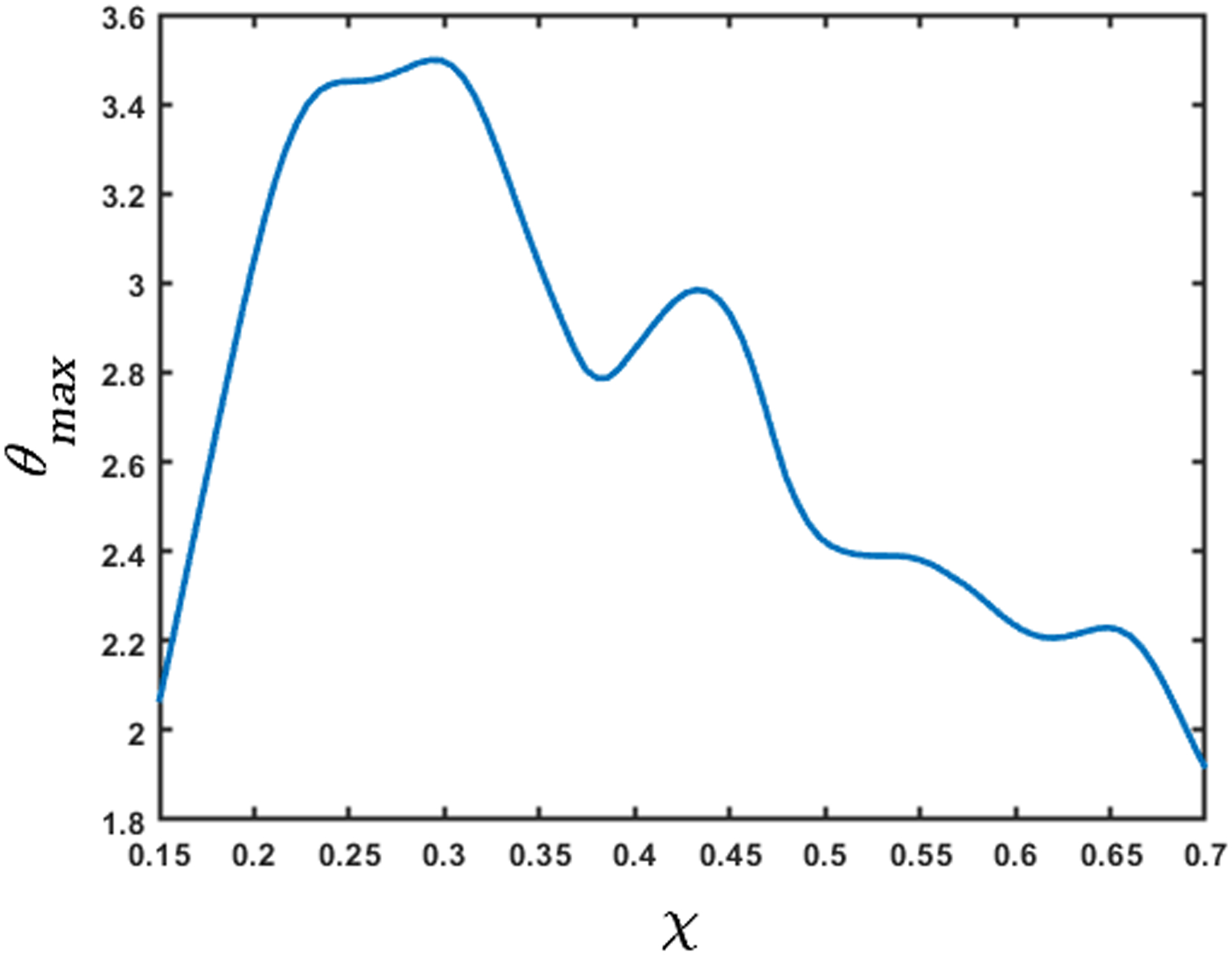
Variation of the maximum active relaxation factor. The x-axis represents the length of the esophagus marked by the dashed horizontal lines in Fig. 13. The high values of θmax correspond to the low values of stiffness. The low values of θmax at the χ = 0.15 and 0.7 are due to the influence of the peristaltic contraction and the LES, respectively.
Although the FluoroMech model provides a simple non-invasive technique to predict esophageal wall stiffness and active relaxation, the fluoroscopy images that are used as input to the model, impose certain limitations to the capability of FluoroMech. Due to the inherent lack of information about the three-dimensional geometry of the bolus, we make some assumptions about the esophageal cross-sectional areas by enforcing volume conservation of the bolus so that the transport follows the physical laws. The cross-sectional areas obtained after volume conservation might not be exactly the same as in reality, and might lead some inaccuracies in our predictions. The dynamic pressure variations due to the unnecessary variations in cross-sectional areas are negligible compared to the static pressure inside the bolus. Therefore, the effect of minor inaccuracies in extracting cross-sectional areas from fluoroscopy images in the prediction of esophageal wall stiffness and active relaxation is mitigated to a reasonable extent. The stiffness predicted by the model can be higher than the actual stiffness at some locations due to the surrounding organs pressing against the esophagus. The prediction of esophageal wall stiffness and active relaxation is sensitive to the relaxed lumen cross-sectional area and the cross-sectional area distal to the bolus, respectively. Identifying these cross-sectional areas in fluoroscopy images is sometimes difficult due to the lack of barium lining the esophageal lumen in such locations. This might add to some inaccuracies in our prediction. FluoroMech can be very easily applied to other imaging techniques such as computed tomography (CT) or magnetic resonance (MR) imaging that can provide a better imaging of the three-dimensional bolus, relaxed lumen cross-section and identify locations where the surrounding organs press against the esophagus, and hence predict wall stiffness and active relaxation more accurately. Additionally, the esophageal wall stiffness prediction is dependent on the accurate measurement of the intragastric and intrathoracic pressure. Therefore, FluoroMech used along with manometry (as described in this work) leads to better prediction of wall stiffness.
5. Conclusion
We have presented FluoroMech, a technique for analyzing fluoroscopy image data using deep learning and computational fluid dynamics. The image sequence from fluoroscopy was segmented using a Convolutional Neural Network to obtain the outline of the bolus as it transits the esophagus. This bolus outline then becomes the input to a computational model that solves the one-dimensional mass and momentum conservation equations to obtain the fluid flow rate and pressure. Since fluoroscopy provides information only about the shape of the bolus in a single two-dimensional plane, we made approximations regarding the esophageal cross-sectional areas to conserve the volume of swallowed fluid. We observed that the static pressure inside the bolus is significantly greater than the dynamic pressure. This indicates that the effect of elastic deformation is significantly greater than combined effect of the viscous drag at the esophageal walls and local acceleration or deceleration of the bolus fluid in pressurizing the bolus fluid. Based on our mechanistic study, we have categorized the esophageal transport into four zones: contraction zone behind the bolus, active relaxation zone at the bolus, stiff zone at the LES and a baseline zone for the remainder of the esophagus.
Using the shape of the bolus and the pressure predicted from this model, we have presented a method to estimate the esophageal wall stiffness. We concluded that the lower values of the predicted stiffness reflect the actual stiffness of the walls since contact with surrounding organs can lead to a higher predicted stiffness. The stiffness predicted by FluoroMech was of the same order and close to the range of values reported in other studies. We also presented a method to estimate active relaxation of the esophagus walls at the bolus using a relaxation factor. Since the dynamic pressure variations are negligible compared to the static pressure inside the bolus, the stiffness and active relaxation estimated by our model are not sensitive to minor inaccuracies in cross-sectional areas extracted from fluoroscopy images. Thus, FluoroMech reliably predicts the state and functioning of the esophagus.
Acknowledgments
We acknowledge the support provided by Public Health Service Grants R01-DK079902 and P01-DK117824, and National Science Foundation Grants OAC 1450374 and OAC 1931372 in the completion of this work. We also acknowledge the computational resources provided by Northwestern University’s Quest High Performance Computing Cluster. For this work, we have also utilized the Extreme Science and Engineering Discovery Environment (XSEDE) cluster Comet, at the San Diego Supercomputer Center through allocation TG-ASC170023, which is supported by National Science Foundation grant number ACI-1548562 [29].
References
- [1].Abadi Martín, Agarwal Ashish, Barham Paul, Brevdo Eugene, Chen Zhifeng, Citro Craig, Corrado Greg S., Davis Andy, Dean Jeffrey, Devin Matthieu, Ghemawat Sanjay, Goodfellow Ian, Harp Andrew, Irving Geoffrey, Isard Michael, Jia Yangqing, Jozefowicz Rafal, Kaiser Lukasz, Kudlur Manjunath, Levenberg Josh, Dan Mané Rajat Monga, Moore Sherry, Murray Derek, Olah Chris, Schuster Mike, Shlens Jonathon, Steiner Benoit, Sutskever Ilya, Talwar Kunal, Tucker Paul, Vanhoucke Vincent, Vasudevan Vijay, Fernanda Viégas Oriol Vinyals, Warden Pete, Wattenberg Martin, Wicke Martin, Yu Yuan, and Zheng Xiaoqiang. TensorFlow: Large-scale machine learning on heterogeneous systems, 2015. Software available from tensorflow.org.
- [2].Barnard ACL, Hunt WA, Timlake WP, and Varley E. A theory of fluid flow in compliant tubes. Biophysical Journal, 6(6):717–724, 1966. [DOI] [PMC free article] [PubMed] [Google Scholar]
- [3].Brasseur James G.. A fluid mechanical perspective on esophageal bolus transport. Dysphagia, 2(1):32, March 1987. [DOI] [PubMed] [Google Scholar]
- [4].Chollet François et al. Keras. https://keras.io, 2015.
- [5].Ciresan Dan, Giusti Alessandro, Gambardella Luca M., and Schmidhuber Jürgen. Deep neural networks segment neuronal membranes in electron microscopy images. In Pereira F, Burges CJC, Bottou L, and Weinberger KQ, editors, Advances in Neural Information Processing Systems 25, pages 2843–2851. Curran Associates, Inc., 2012. [Google Scholar]
- [6].Coleman GB and Andrews HC. Image segmentation by clustering. Proceedings of the IEEE, 67(5):773–785, May 1979. [Google Scholar]
- [7].Ghosh Sudip K., Kahrilas Peter J., Zaki Tamer, Pandolfino John E., Joehl Raymond J., and Brasseur James G.. The mechanical basis of impaired esophageal emptying postfundoplication. Am J Physiol Gastrointest Liver Physiol, 289:G21–G35, 2005. [DOI] [PubMed] [Google Scholar]
- [8].Iglovikov Vladimir and Shvets Alexey. Ternausnet: U-net with VGG11 encoder pre-trained on imagenet for image segmentation. CoRR, abs/1801.05746, 2018. [Google Scholar]
- [9].Jacob P, Kahrilas PJ, Logemann JA, Shah V, and Ha T. Upper esophageal sphincter opening and modulation during swallowing. Gastroenterology, 97(6):1469–1478, 1989. [DOI] [PubMed] [Google Scholar]
- [10].Kamm Roger D. and Shapiro Ascher H.. Unsteady flow in a collapsible tube subjected to external pressure or body forces. Journal of Fluid Mechanics, 95(1):1–78, 1979. [Google Scholar]
- [11].Kayalibay Baris, Jensen Grady, and van der Smagt Patrick. Cnn-based segmentation of medical imaging data. CoRR, abs/1701.03056, 2017. [Google Scholar]
- [12].Kou W, Bhalla AP, Griffith BE, Pandolfino JE, Kahrilas PJ, and Patankar NA. A fully resolved active musculo-mechanical model for esophageal transport. Journal of Computational Physics, 298:446–465, 2015. [DOI] [PMC free article] [PubMed] [Google Scholar]
- [13].Kou Wenjun, Griffith Boyce E., Pandolfino John E., Kahrilas Peter J., and Patankar Neelesh A.. A continuum mechanics-based musculo-mechanical model for esophageal transport. Journal of Computational Physics, 348:433–459, 2017. [DOI] [PMC free article] [PubMed] [Google Scholar]
- [14].Kwiatek Monika A., Hirano Ikuo, Kahrilas Peter J., Rothe Jami, Luger Daniel, and Pandolfino John E.. Mechanical properties of the esophagus in eosinophilic esophagitis. Gastroenterology, 140(1):82–90, 2011. [DOI] [PMC free article] [PubMed] [Google Scholar]
- [15].Lang Ivan M and Shaker Reza. Anatomy and physiology of the upper esophageal sphincter. The American Journal of Medicine, 103(5, Supplement 1):50S–55S, 1997. [DOI] [PubMed] [Google Scholar]
- [16].Li M, Brasseur JG, and Dodds WJ. Analyses of normal and abnormal esophageal transport using computer simulations. American Journal of Physiology-Gastrointestinal and Liver Physiology, 266(4):G525–G543, 1994. [DOI] [PubMed] [Google Scholar]
- [17].Li Meijing and Brasseur James G.. Non-steady peristaltic transport in finite-length tubes. Journal of Fluid Mechanics, 248:129–151, 1993. [Google Scholar]
- [18].Manopoulos Christos G., Mathioulakis Demetri S., and Tsangaris Sokrates G.. One-dimensional model of valveless pumping in a closed loop and a numerical solution. Physics of Fluids, 18(1):017106, 2006. [Google Scholar]
- [19].Mittal Ravinder. Motor function of the pharynx, esophagus, and its sphincters. Colloquium Series on Integrated Systems Physiology: From Molecule to Function, 3(3):1–84, 2011. [Google Scholar]
- [20].Orvar Kjartan B., Gregersen Hans, and Christensen James. Biomechanical characteristics of the human esophagus. Digestive Diseases and Sciences, 38:197–205, 1993. [DOI] [PubMed] [Google Scholar]
- [21].Ottesen JT. Valveless pumping in a fluid-filled closed elastic tube-system: one-dimensional theory with experimental validation. Journal of Mathematical Biology, 46(4):309–332, April 2003. [DOI] [PubMed] [Google Scholar]
- [22].Pal Nikhil R and Pal Sankar K. A review on image segmentation techniques. Pattern Recognition, 26(9):1277–1294, 1993. [Google Scholar]
- [23].Patel Rig S. and Rao Satish S. C.. Biomechanical and sensory parameters of the human esophagus at four levels. American Journal of Physiology-Gastrointestinal and Liver Physiology, 275(2):G187–G191, 1998. [DOI] [PubMed] [Google Scholar]
- [24].Pham Dzung L., Xu Chenyang, and Prince Jerry L.. Current methods in medical image segmentation. Annual Review of Biomedical Engineering, 2(1):315–337, 2000. [DOI] [PubMed] [Google Scholar]
- [25].Ronneberger Olaf, Fischer Philipp, and Brox Thomas. U-net: Convolutional networks for biomedical image segmentation. CoRR, abs/1505.04597, 2015. [Google Scholar]
- [26].Sahoo PK, Soltani S, and Wong AKC. A survey of thresholding techniques. Computer Vision, Graphics, and Image Processing, 41(2):233–260, 1988. [Google Scholar]
- [27].Senthilkumar R, Bharathi A, Sowmya B, and Sugunamuki KR. Image segmentation edge detection techniques using - soft computing approaches. pages 1–6, February 2018.
- [28].Sharma Neeraj and Aggarwal Lalit. Automated medical image segmentation techniques. Journal of Medical Physics, 35(1):3–14, 2010. [DOI] [PMC free article] [PubMed] [Google Scholar]
- [29].Towns J, Cockerill T, Dahan M, Foster I, Gaither K, Grimshaw A, Hazlewood V, Lathrop S, Lifka D, Peterson GD, Roskies R, Scott JR, and Wilkins-Diehr N. Xsede: Accelerating scientific discovery. Computing in Science & Engineering, 16(5):62–74, Sep-Oct 2014. [Google Scholar]
- [30].Xia Fan, Mao Jingfang, Ding Jinquan, and Yang Huanjun. Observation of normal appearance and wall thickness of esophagus on ct images. European Journal of Radiology, 72(3):406–411, 2009. [DOI] [PubMed] [Google Scholar]
- [31].Yang Wei, Fung Tat Ching, Chian Kerm Sim, and Chong Chuh Khiun. Finite element simulation of food transport through the esophageal body. World journal of gastroenterology, 13(9):1352—1359, March 2007. [DOI] [PMC free article] [PubMed] [Google Scholar]


