Abstract
Arterial spin labelling is an emerging non-invasive magnetic resonance imaging technique for estimating the cerebral perfusion without the requirement for gadolinium-based intravenous contrast agents. Despite the wide range of applications in epilepsy, dementia, brain tumours, vascular malformations and stroke imaging, obtaining clinically useful arterial spin labelling data is technically challenging and prone to numerous artefacts. The objective of this review is to provide a comprehensive pictorial overview of the various artefacts associated with arterial spin labelling, particularly three-dimensional fast spin echo pseudocontinuous arterial spin labelling with spiral readout. These artefacts could be broadly classified as those occurring during the magnetic labelling, arterial transit or image acquisition. Arterial spin labelling artefacts of clinical diagnostic utility are also elaborated. A thorough knowledge of the basis of these artefacts will avoid diagnostic pitfalls while interpreting arterial spin labelling images. Important tips to reduce or overcome these artefacts are also discussed.
Keywords: Arterial spin labelling (ASL), artefact, magnetic resonance imaging (MRI), post label delay (PLD), arterial transit artefact (ATA)
Introduction
Arterial spin labelling (ASL) has recently emerged as a novel non-invasive magnetic resonance imaging (MRI) technique for estimating the cerebral blood flow (CBF) quantitatively, which uses the magnetically labelled water in the flowing blood as the endogenous tracer to estimate cerebral perfusion.1,2 This technique is emerging to be used as a substitute for routinely available diagnostic investigative methods such as dynamic susceptibility contrast (DSC) perfusion and positron emission tomography (PET). The DSC method uses exogenous gadolinium chelate bolus as a tracer for the estimation of cerebral perfusion, whereas PET studies require radioactive ligands such as fluorodeoxyglucose for this purpose. Needless to say, these methods are more invasive and may not be repeatable as often as required by the clinical need for follow-up imaging. Again, with increasing awareness of gadolinium deposition in the brain and its higher risk of usage in vulnerable populations such as patients with renal insufficiency, magnetic resonance contrast media need to be administered with heightened caution in clinical practice. ASL, due to its non-invasive nature, is well suited to be considered as an alternative method for estimating CBF especially in the paediatric population and in patients with renal insufficiency.3,4 ASL MRI can be performed with technical variants such as pulsed arterial spin labelling (pASL), continuous arterial spin labelling (cASL) or pseudocontinuous arterial spin labelling (pcASL).4 pASL uses pulsed tagging of arterial water at the skull base whereas cASL uses continuous tagging. The former has the advantage of reduced tissue energy deposition (specific absorption ratio (SAR)), but with compromised signal strength. cASL, however, has a better signal to noise ratio (SNR), but with increased SAR. pcASL is a hybrid technique which combines the advantages of both the above techniques. Various advances and modifications of these techniques, such as the use of higher magnetic field strength, parallel imaging and three-dimensional (3D) acquisition methods have significantly improved the diagnostic quality of ASL images in the recent past.4–9 However, obtaining clinically useful ASL images is technically challenging and prone to numerous artefacts even now. These artefacts are commonly encountered in clinical imaging and a thorough knowledge of the basis of these artefacts and the remedies will avoid diagnostic pitfalls while interpreting ASL images.
Learning objectives
A quick overview of the technical aspects of ASL sequences.
Identification of commonly encountered ASL artefacts and the diagnostic utility of some of them.
Remedies to prevent, overcome or attenuate these artefacts in clinical practice.
Principles of ASL
The arterial blood water is magnetically labelled or tagged using an adiabatic inversion pulse to invert the spins at a plane caudal to the brain (upper neck). The negative magnetisation of these inflowing, magnetically inverted water protons mixes with the positive magnetisation of static tissue water protons, resulting in a small signal intensity decrease of 1–2%. Following a specific post-label delay (PLD), which is typically around 1.5 to 2.5 seconds, tagged images of the brain are acquired. A control image without tagging is also obtained. Subtraction of the tagged image from the control image gives the measure of this small signal intensity decrease, which is proportional to the CBF. Multiple acquisitions of the tagged and control paired images are performed, to improve the SNR. These differences in ASL images can be converted to absolute CBF maps based on the patient’s proton density images.4,9–11
There are different schemes of ASL implementation with pulsed or continuous tagging with two-dimensional or 3D acquisition schemes as previously mentioned.11 A recent consensus recommendation by the International Society for Magnetic Resonance in Medicine (ISMRM) Perfusion Study Group and the European Consortium for ASL in Dementia is to use 3D pcASL in clinical studies.12 This sequence has the advantage of a better SNR with acceptable SARs compared to pASL and cASL techniques, respectively.
Materials and methods
We have used representative images of cases encountered in clinical practice, from the picture archiving communication system at our institution, ASL is being performed on a 3T GE Discovery 750 W scanner (GE Healthcare, Milwaukee, WI, USA) using a 3D pcASL technique with the following technical parameters: Time to Repeat/Time to Echo (TR/TE 4852 ms/10.7 ms), PLD 2025 ms (adults), 1025–1525 (children), field of view (FOV) 24 × 24 cm, Number of excitations (NEX-3), slice thickness 4 mm in axial sections along the anterior commissure–posterior commissure (AC–PC) line. The average scan time was approximately 4.5–5 minutes. When artefacts were encountered, a repeat ASL sequence was acquired after modifying the ASL parameters (PLD)/patient positioning/tagging plane, etc., varying according to the requirement.
ASL artefacts
Artefacts can arise during various stages of sequence acquisition; that is, during tagging (magnetic labelling period), during transit (time between the tagging and image acquisition) or during the read-out phase (image acquisition). Various physiological changes also produce artefacts, which a radiologist must be aware of while interpreting ASL images.
The main aim of this review is to illustrate the numerous ASL artefacts, especially arising from the 3D pcASL scheme, with a special focus on how to identify, avoid, rectify or reduce them, and to interpret a few clinically relevant artefacts of high diagnostic sensitivity, which are useful in clinching the diagnosis in some cases. We have illustrated the artefacts encountered with 3D pcASL images acquired using the fast spin echo (FSE) ASL technique. Acquisition techniques used by other MRI schemes may show similar or different artefacts, or the artefacts have a different appearance. The artefacts are classified in Table 1 and detailed with remedial measures in Table 2 (modified from Amukotuwa et al.).13
Table 1.
Classification of pseudocontinuous ASL artefacts.
| Arising during labeling | Arising during transit | Arising during read-out/image acquisition |
|---|---|---|
| Ineffective labelling | Loss of spin label | Motion-related artefact |
| CSF labelling | Intra-arterial ASL artefact• Arterial transit artefact• Border zone artefact• Trapped ASL signal | Blurring |
| Occipital lobe hyperperfusion | ||
| Venous ASL signal |
CSF: cerebrospinal fluid; ASL: arterial spin labelling.
Modified from Amukotuwa et al.13
Table 2.
Summary of the various pseudocontinuous ASL artefacts, MRI appearance and technical remedies.
| Artefact | Cause | Technical explanation | MRI ASL appearance | Remedy |
|---|---|---|---|---|
| During labelling | ||||
| Ineffective labelling | Tortuosity of vessel in the tagging plane | Improper tagging of the blood in the vessel | Signal drop-out in the affected vascular territory | Changing the location of the tagging planeAcquiring a low resolution MRA prior to planning ASL may help |
| Susceptibility variations near tagging plane (e.g. metallic material) | Removal of the source of susceptibility, if possible | |||
| Head tilt/improper head flexion/extension | Ensure neutral symmetric head position | |||
| CSF labelling | Due to the pulsatile flow of CSF | Tagged CSF moves into the imaging plane | ‘Ring of fire’ appearance – high signal in peri-medullary CSF | Placing the tagging plane more caudally, so that CSF if tagged is attenuated as it reaches the imaging plane |
| During transit | ||||
| Loss of spin label | Administration of gadolinium-based contrast agent prior to ASL | Gadolinium decreases the T1 relaxation time > tagged arterial spins quickly decay back to equilibrium state, before reaching imaging volume | Complete absence of ASL signal in the whole brain parenchyma | Acquisition of ASL mages prior to administration of gadolinium |
| Arterial transit artefact | Delayed arterial transit (diminished cardiac output or arterial stenosis) | Transit time of arterial blood from tagging to imaging plane > PLD; labelled spins still in the intra-arterial compartment at time of imaging | Intra-arterial ASL signal: serpiginous high ASL signal in the basal cisterns and cortical sulci. Low parenchymal ASL signal-labelled blood has not yet reached parenchymal capillary bed nor undergone tissue exchange | Increase the PLD or use multi-delay ASL |
| Border zone artefact | Diminished blood flow in the watershed zones of the brain | Transit time of arterial blood from tagging to imaging plane > PLD; labelled spins still in the intra-arterial compartment at time of imaging | Paucity of signal in brain parenchyma more pronounced in the arterial watershed regions (mainly parieto-occipital) | Increase the PLD |
| Trapped ASL signal | Intracranial aneurysm or slow flow within vessels due to distal occlusion | Labelled spins still within the aneurysm sac or proximal to the site of arrest of flow at the time of imaging due to turbulent flow | High signal in the aneurysm sac or the distal end of the patent vessel before the occlusion | Bipolar crusher gradients applied prior to imaging the parenchyma can be used to suppress intra-arterial ASL signal |
| Venous ASL signal | Direct and/or rapid transit of blood from arteries into the venous sideUsually seen with arteriovenous shunting (e.g, most commonly high-flow vascular malformations) | The normal capillary bed is bypassed, therefore labelled water has not undergone tissue exchange, and there is incomplete T1 relaxation of labelled blood water detected in the venous side | High ASL signal in venous structures | No remedy – may aid in the diagnosis of AVF/AVM |
| During the read-out/acquisition | ||||
| Motion | Severe patient head motion | Misregistration of spins between the control and tagged images during spiral K space filling | High signal intensity spirals (seen in stacked spirals acquisition) | Avoid motion of the subject |
| Blurring | Stagnation of tagged spins | Stack of spirals acquisition | Smearing or streaking of high signal intensity structure along craniocaudal direction | Decreasing the number of slices in the Z direction |
| Use vascular suppression gradients | ||||
| Use of an alternative readout (echo planar imaging) | ||||
| Occipital lobe hyperperfusion | Patient’s eyes open during scan | Physiological occipital lobe activation | High ASL signal in the occipital lobes bilaterally | Patient is instructed to close eyes during acquisition |
CSF: cerebrospinal fluid; ASL: arterial spin labelling; AVF: arteriovenous fistula; AVM: arteriovenous malformation; PLD: post-label delay; MRI: magnetic resonance imaging; MRA: magnetic resonance angiogram.
Modified from Amukotuwa et al.13
Artefacts arising during labelling
Ineffective labelling of the flowing arterial blood water
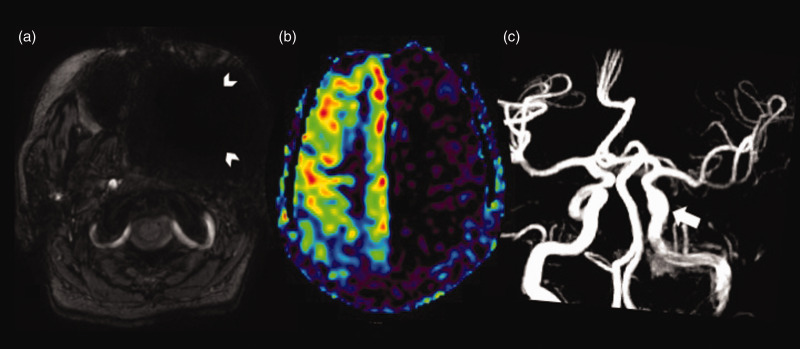
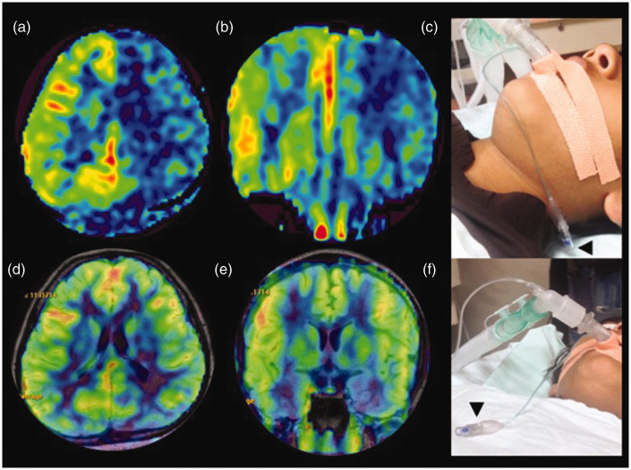
As a result of the tortuosity of the vessel in the tagging plane (a common finding in the elderly or hypertensive patients with tortuous neck vessels) or due to susceptibility variations near the tagging plane, such as metallic dental hardware (Figure 1) or anaesthetic devices (Figure 2) used for maintaining the airway in patients undergoing MRI under anaesthesia, a particular vessel may be less effectively labelled. The ASL images show signal drop-out in the affected vascular territory. Similar artefact may be encountered if the subject’s head is tilted or hyper-flexed/hyperextended, which may result in non-tagging, or asymmetrical tagging of a particular vessel leading to territorial signal drop-out or non- physiological asymmetric signal representation, which could be mistaken for pathological signal changes. A tortuous vessel may not be perpendicular to the direction of tagging, and marked tortuosity of the neck vessel causes blood to pass through the labelling plane more than once, hence resulting in poor labelling efficiency as it encounters multiple inversion pulses.13 This can be overcome by changing the location of the tagging plane if the artefact was due to vessel tortuosity. The acquisition of a low resolution magnetic resonance angiogram prior to ASL to assess the neck vessels is useful in planning the tagging plane in cases of neck vessel tortuosity.11 Removal of the susceptibility-inducing metallic object – when possible – or modifying the tagging plane to avoid the source of susceptibility will also help to reduce the territorial signal loss (Figure 2(d)–(f)).
Figure 1.
Susceptibility artefact from a metallic denture in the left maxillo-facial region. (a) Susceptibility weighted imaging showing hypointensity due to blooming in the left maxillo-facial region (white arrowheads). (b) Arterial spin labelling image showing signal loss in the left internal carotid artery (ICA) territory (white arrowheads). (c) Normal cavernous and supraclinoid segments of the left ICA (white arrow) on the time of flight magnetic resonance angiography reformatted image.
Figure 2.
Susceptibility artefact from the pilot balloon of the endotracheal tube. (a) and (b) Axial and coronal arterial spin labelling (ASL) images showing signal drop-out in the left internal carotid artery (ICA) territory due to susceptibility artefact from the metallic spring in the pilot balloon of the endotracheal tube (black arrowhead) in the left upper neck (c). (d) and (e) Axial and coronal reformatted ASL images showing normal signal in the left ICA territory after the pilot balloon of the endotracheal tube (black arrowhead) has been moved away from the tagging plane (f).
CSF labelling artefact
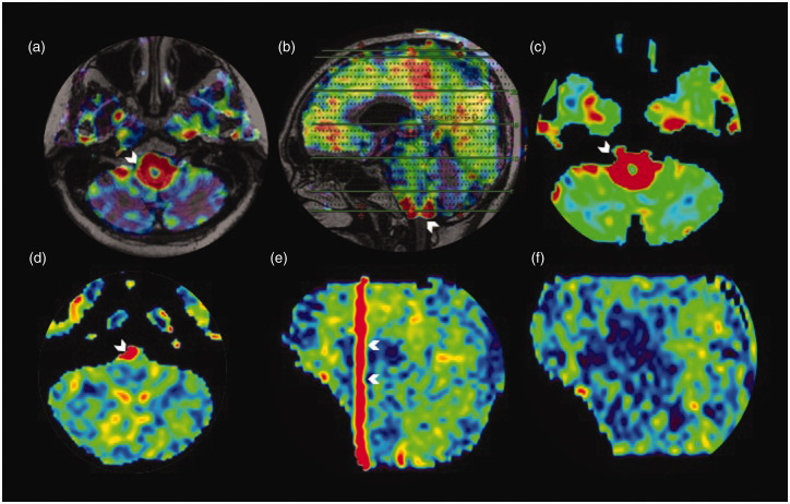
Due to the pulsatile flow of the cerebrospinal fluid (CSF), CSF tagged in the plane moves into the imaging plane. This is seen in ASL images as an area of increased ASL signal in the peri-medullary CSF space, giving rise to the ‘ring of fire’ artefact (Figure 3(a)). Sometimes the ‘ring’ can be partial (Figure 3(d)), occurring only on the anterior or posterior part of the foramen magnum. The blurring of the 3D spiral read-out smears the CSF artefact in the Z-axis (Figure 3(e)). This can be overcome by placing the tagging plane more caudally so that the tagged CSF does not reach the imaging plane within the PLD time. The technical explanation for the blurring/smearing artefact occurring in CSF labelling is detailed in the section ‘Trapped ASL signal’.
Figure 3.
Cerebrospinal fluid (CSF) labelling artefact. Axial arterial spin labelling (ASL) fluid-attenuated inversion recovery (FLAIR) sequence fused and unfused ASL image (a) and (c), respectively, showing the increased peri-medullary CSF bright red signal (shown by white arrowhead), which is also demonstrated in the sagittal reformatted FLAIR ASL fused image (white arrowhead in (b)).The axial ASL image (d) in a different patient showing the partial ring of fire artefact, seen as a high signal in the right cerebello-medullary and cerebello-pontine cistern (white arrowhead). Sagittal reformat showing the craniocaudal smearing (arrowheads in (e)). After relocating the labelling plane the artefact is eliminated (sagittal reformat (f)).
Artefacts arising during transit of labelled spins
Loss of spin label
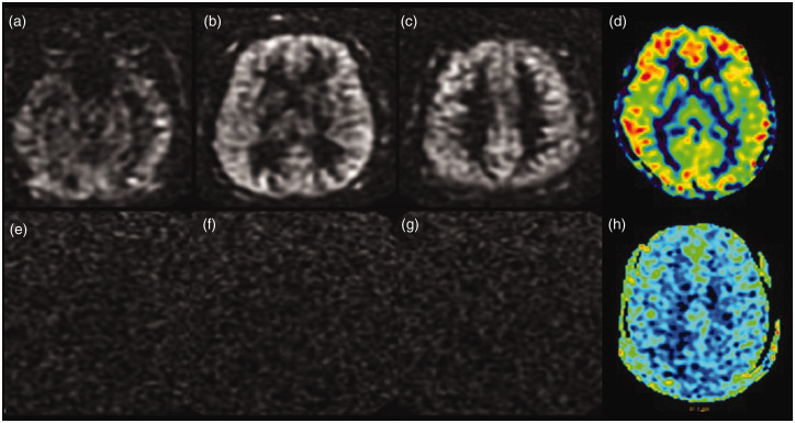
Gadolinium-based contrast administration prior to the acquisition of ASL can result in a significant signal loss in the images. The tagged blood water spins decay sooner to an equilibrium state, due to T1 reduction induced by gadolinium, before the passage through the parenchyma.14 The resultant ASL image shows complete loss of signal (Figure 4(e)–(g)). Hence ASL images should be acquired prior to administering intravenous gadolinium to obtain clinically useful information.9,13
Figure 4.
Loss of spin labelling post-gadolinium injection. Serial axial tagged raw arterial spin labelling (ASL) images before the administration of gadolinium (a)–(c) and the processed colour image (d) showing good parenchymal perfusion. Source images (e)–(g) and the processed colour image (h) obtained after the administration of gadolinium-based contrast show the complete absence of ASL signal.
In ASL, the tissue magnetisation of the voxel can be described by the Bloch equation as:
| (1) |
Where, Mb(t) is the longitudinal magnetisation per gram of brain tissue as a function of time; M0b is the value of Mb under fully relaxed conditions; T1 is the spin lattice relaxation time constant of free water protons, in the absence of flow; f is the brain blood flow in ml.g−1s−1; λ is the blood brain water partition coefficient in ml.g−1; Ma is arterial magnetisation per ml of blood.15
From equation (1) Mb will be a function of T1 of the brain water and the blood flow. Administration of gadolinium-based contrast agents into the blood pool changes the relaxation rate of water in the blood. So, the change in the longitudinal relaxation rate of water in the blood can be estimated from the relaxivity (ra) and the concentration of contrast agent (cb) in the blood by the equation:
| (2) |
Where Ra is 1/T1 and R0a is the intrinsic relaxation of water in the blood.16 Ultimately, the use of paramagnetic contrast agents affects the signal intensity of labelled images. The T1 values in the normal tissues are related to the macromolecular concentration, water binding and water content. In ASL, spin lattice relaxation is an important parameter as the difference in longitudinal magnetisation gives the image contrast related to the blood flow.
Intra-arterial ASL artefacts
Arterial transit artefact
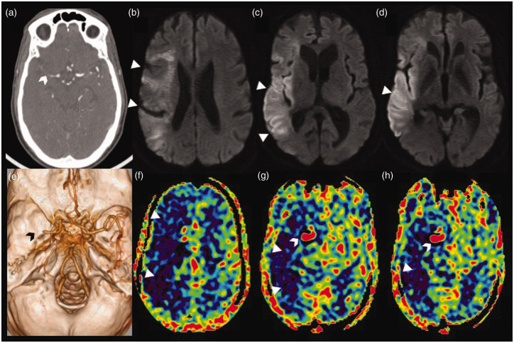
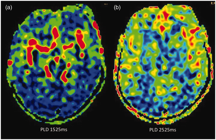
Delayed arterial transit may occur as a result of a significant arterial stenosis during the course of the passage of the labelled spin due to reduced flow as a result of physiological causes such as reduced cardiac output or increased resistance to distal flow.13,17 This causes the labelled spins to remain still in the intra-arterial compartment at the time of imaging as the transit time of arterial blood from the tagging plane to the imaging plane is longer than the PLD. The typical imaging findings are those of linear and serpiginous high ASL signals in basal cisterns and/or cortical sulci where the major intracranial arteries or branches lie, (corresponding to intra-arterial ASL signal) (Figure 5). This is associated with low parenchymal CBF as the labelled blood has not yet reached the parenchymal capillary bed.13,18,19 The blood within the major neck vessels (the carotid and vertebral arteries) is magnetically labelled in the neck and it takes a few seconds for the moving blood to reach the cortical capillaries. Hence the image acquisition (read-out) starts after a specific delay (the PLD) to acquire a parenchymal phase. Due to T1 relaxation there is a rapid signal decay of the labelled blood which allows only a narrow time window for image acquisition to achieve an adequate SNR. In cases of significant stenosis of an intracranial vessel distal to the tagging plane, this time window is further narrowed due to the delay in the bolus arrival time (BAT) and hence the particular vascular territory shows a low ASL signal. There is also simultaneous stagnation of the labelled spins proximal to the stenosis/occlusion, as demonstrated in a case of acute stroke in Figure 6, which causes a ‘blurring’ or ‘smearing’ artefact in the craniocaudal direction seen only in cases of segmented 3D FSE ASL acquisition with a ‘stack of spirals’ read-out.13,20 Arterial transit artefact (ATA) can be caused as a result of slow flow in the vessel proximal to narrowing or occlusion as in acute stroke (Figure 6). This is rectified by increasing the PLD (Figure 7) or by using multi-delay ASL. However, it should be noted that in ASL quantification, blood T1 assumes a significant role as previously mentioned and increasing the PLD will result in further T1 decay, which can reduce the intensity of ASL signals in the resultant image. To counter this, strategies such as either a multi-PLD ASL protocol with special software or a subtraction method with dual PLD are to be used.
Figure 5.
Arterial transit artefact. Axial arterial spin labelling (ASL) images (a) and (b) showing increased serpiginous ASL signal in the right fronto-temporal region (white arrowheads) – corresponding to the tortuous vessels on conventional images – time of flight magnetic resonance angiography (arrowhead in (c)) and susceptibility weighted axial image (arrowhead in (d)).
Figure 6.
Stagnation of arterial spin labelling (ASL) signal due to distal occlusion in an acute right middle cerebral artery (MCA) stroke. Axial computed tomographic angiogram image (a) showing cut-off of the proximal M1 segment of the right MCA with faint contrast opacification of the distal M1 MCA (white arrowhead). Volume rendered angiographic image (e) showing the right M1 MCA cut-off (black arrowhead) with paucity of the cortical branches. Serial axial diffusion weighted images (b)–(d) showing areas of diffusion restriction (white triangles) in the cortical right MCA territory with relative sparing of the ganglio-capsular region. Serial axial ASL images at corresponding levels (f)–(h) showing a larger area of perfusion defect, seen as a low ASL signal (white triangles), with increased ASL signal (white arrowhead) within the communicating segment of the right internal carotid artery and the patent proximal right MCA stump due to stagnation of labelled spins (arterial transit artefact).
Figure 7.
Reduction in arterial transit artefact (ATA) and improvement in parenchymal arterial spin labelling (ASL) signal by changing the post-labelling delay (PLD). In this paediatric patient who had undergone magnetic resonance imaging under anaesthesia, when ASL was acquired with the standard PLD of 1525 ms in children, there was significant ATA (a), possibly due to intravenous anaesthetic medication, and when the PLD was increased to 2525 ms the ATA has largely disappeared with improved parenchymal perfusion (b). A time of flight magnetic resonance angiography of the circle of Willis (not shown) was normal.
Border zone artefact
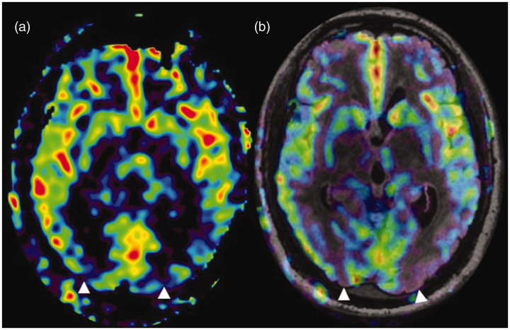
A low ASL signal in the arterial border zones results from diminished perfusion in the watershed zones of the brain parenchyma especially posteriorly (Figure 8). Increasing the PLD may improve the overall parenchymal signal but the watershed regions may still show hypoperfusion.21 These border zone signs are often accentuated when there is an ATA due to some underlying cause.
Figure 8.
Border zone sign. (a) and (b) Arterial spin labelling (ASL) processed image and ASL fluid attenuated inversion recovery (FLAIR) sequence fused image, respectively, showing parenchymal hypoperfusion in the parieto-occipital regions (watershed zones) (white triangles) in a patient with an ejection fraction of 24%.
Trapped ASL signal
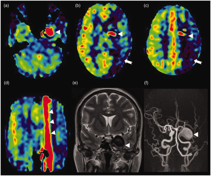
This finding is classically seen in aneurysms in which the labelled spins are still within the aneurysmal sac at time of imaging due to the turbulent flow, resulting in a high ASL signal within the aneurysm. This can also lead to a ‘smearing’ or ‘blurring’ artefact of the high ASL signal in the craniocaudal direction due to stack of spirals read-out in segmented 3D FSE ASL (Figure 9).13,18--20 In 3D pcASL with spiral read-out, phase encoding is performed along the slice direction and spiral encoding only in-plane. In the case of an aneurysm, the labelled spins are trapped within the aneurysm and this stagnation causes the high ASL in the K space corresponding to the anatomical location of the aneurysm signal relative to the background suppression. This causes a large and abrupt bright to dark intensity difference at its interface with the background, and accentuates the Gibbs ringing in the slice-encoding direction in the tagged image. With the use of Fourier transform, any object may be represented as a sum of multiple sine or cosine waves, each with a given amplitude and frequency. Fourier transform is the accurate method of depicting regions where there is a gradual change in signal intensity. An abrupt change in signal intensity at interfaces (in this case, the high ASL signal from trapped spins and the low signal of the suppressed background tissue) results in imprecise representation of the tissue interfaces and the tissues adjacent to interfaces. This imprecision is represented on the images by the Gibbs ringing phenomena.20 3D ASL images have few phase-encoding steps which makes the Gibbs ringing more pronounced, and is seen as a high signal streaking in the Z direction in the final ASL image. According to the study by Amukotuwa et al.,13 the radial K space filling is the cause of this artefact. We do not have any valid technical explanation regarding how the peculiarity of the K space filling causes this streaking artefact.13 The improper tagging of the pulsatile CSF in the cervical region at the tagging plane causes the tagged spins to get concentrated in the peri-medullary CSF, giving rise to a high ASL signal. This may again be seen as a smearing artefact cranial and caudal to the slice of increased peri-medullary CSF signal due to the Gibbs ringing effect. As this occurs along the slice-encoding direction (Z axis) it is better appreciated in coronal and sagittal reformatted ASL images.
Figure 9.
Trapped arterial spin labelling (ASL) signal in a giant aneurysm. Axial ASL image (a) showing increased ASL signal (white triangle) within the patent part of the giant aneurysm involving the cavernous segment of the left internal carotid artery. (b) and (c) Low ASL signal of the left internal carotid artery (ICA) territory (white arrow) mimicking hypoperfusion. This is most likely due to a delay in the arrival of labelled spins to the perfusion territory as they are trapped in the aneurysm. In addition, a minimal vascular steal effect may also contribute to the reduction in perfusion. The stagnation of spins within the aneurysm is seen as an increased ASL signal (white triangle) which is smearing craniocaudal to the aneurysm, better illustrated in the coronal reformatted ASL image (white triangles in (d)). T2 coronal image (e) showing the hypointense large left para-cavernous lesion with a signal intensity similar to the vascular flow voids (white triangle). Maximum intensity projections of time of flight magnetic resonance angiography (f) showing the giant right cavernous ICA aneurysm (white triangle).
Venous ASL signal
Most of the magnetically labelled arterial water is exchanged at the capillary level with tissue water, giving rise to the parenchymal ASL signal, when the capillary bed is normal with no vascular shunting. The labelled water being a diffusible tracer has a much longer ‘mean transit time’ in the imaging voxel (of about one second) and by this time, due to the much shorter T1 decay of labelled water, most labelled water will relax within the parenchyma or tissue capillary bed. Hence no significant venous ASL is observed in the normal brain venous system.
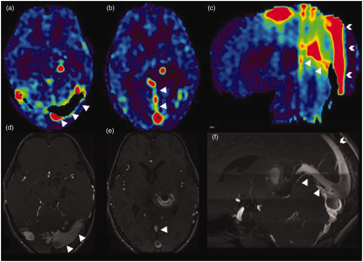
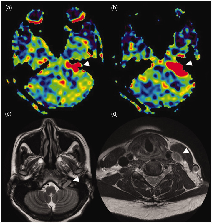
A high ASL signal in the venous structures (‘light bulb sign’) is seen in cases where there is a direct transit of blood from the artery to the veins. This is usually seen with arteriovenous shunting, most commonly high-flow arteriovenous connections without an intervening capillary bed, as seen in dural arteriovenous fistulas (DAVFs) (Figure 10), carotid cavernous fistula or arteriovenous malformations.22 The venous ASL signal alerts the radiologist to the possibility of an underlying shunting lesion, which may be occult on conventional MRI images. This finding warrants further evaluation with dedicated vascular imaging such as digital subtraction angiography. The venous ASL signal artefact may also be useful in the follow-up of such shunting lesions after treatment, as it can indicate shunt recurrence or persistence following therapy. Another clinical application lies in the detection of jugular stenosis or narrowing, which would result in a reversal of flow direction in the sigmoid sinus. Normally intracranial dural sinuses show a caudal flow, hence the tagged venous blood spins do not enter the imaging plane. However, venous reflux of blood from the internal jugular vein (IJV) into the sigmoid sinus can lead to ASL signal even with the absence of any arteriovenous shunts or vascular malformations. Figure 11 shows the venous ASL signal within the left IJV in the jugular fossa due to retrograde reflux flow, secondary to distal left IJV stenosis in the lower neck.
Figure 10.
Venous arterial spin labelling (ASL) signal in a dural arteriovenous fistula (DAVF). A case of a transverse and torcular DAVF. Axial ASL images (a) and (b) showing increased venous signal in the bilateral (left > right) transverse sinuses (white triangles in (a)) and in the torcula and straight sinus (white triangles in (b)) due to the fistula. The sagittal reformatted ASL image (c) showing increased venous signal in the straight sinus (white triangles) and posterior third of the superior sagittal sinus (white arrowheads) due to the venous reflux. This finding is confirmed by the corresponding time of flight magnetic resonance angiography (TOF MRA) midsagittal image (f). The white triangles in the axial TOF MRA images (d) and (e) showing the transverse sinus DAVF and prominent straight sinus, respectively.
Figure 11.
Venous arterial spin labelling (ASL) signal in jugular stenosis. (a) and (b) Axial ASL images showing increased signal in the left jugular fossa and distal left sigmoid sinus (white triangle). T2 axial image at the level of the skull base (c) showing loss of left internal jugular vein (IJV) flow void (white triangle). The left IJV in the neck (d) shows loss of intraluminal flow void (white triangle) due to slow flow (from IJV stenosis in the lower neck confirmed on Doppler ultrasound imaging (not shown).
Artefacts arising during read-out
Motion artefact
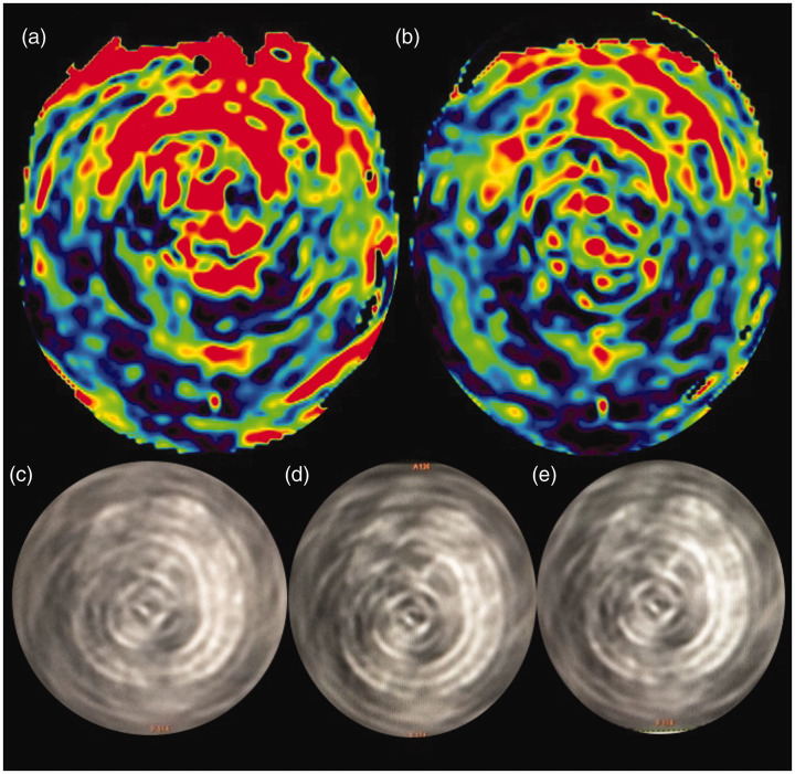
Severe patient motion affects the ASL image quality, seen as high signal intensity spirals in the case of 3D pcASL with stack of spirals read-out. Figure 12 shows an example of such spirals of high signal intensity.
Figure 12.
Motion-related spiral artefact. (a) and (b) Axial processed arterial spin labelling (ASL) images acquired with background suppression in an uncooperative paediatric patient. Severe head motion has led to spirals of high signal intensity due to the spiral three-dimensional read-out mode, inherent to these sequences. (c)–(e) Sequential axial source images of the same patient. Diagnostic quality images were re-obtained with patient sedation (images not shown).
Blurring
Blurring occurs as a result of stacking of signals and can cause a ‘smearing’ artefact, which is seen as an increased ASL signal in a craniocaudal direction (Figure 8(d)). This finding is better appreciated on the coronal and sagittal reformatted ASL images. The blurring can be reduced by decreasing the number of slices in the Z direction.13 If the source of the high signal is a vascular structure with flowing blood, such as an aneurysm, one could consider repeating the ASL sequence with vascular suppression gradients, to eliminate the high signal so that it cannot propagate in the craniocaudal direction. However, the detection of this artefact will sometimes contribute to the diagnostic sensitivity in such conditions as aneurysms of reversal or stagnant flow in a higher grade DAVF.
Occipital lobe hyperperfusion
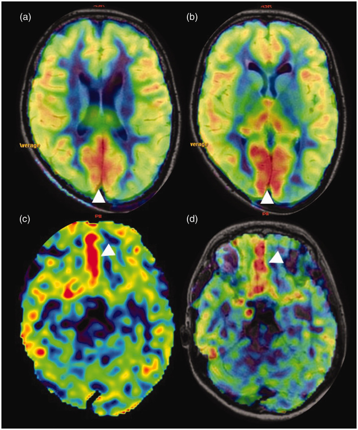
Physiological activation of the occipital lobes occurred as the patient’s eyes were open during the scan. This is seen as an increased ASL signal in the bilateral occipital lobes (Figure 13(a) and (b)) and is eliminated by instructing the patient to keep their eyes closed during the image acquisition. The physiological increase in ASL signal has broadened the outlook of functional ASL which can be a potential substitute for blood oxygenation level dependent functional MRI.9,23 The current limitation of this amazing prospect is the poor SNR of ASL images necessitating the averaging of multiple acquisitions. Relative hyperperfusion of the basi-frontal cortices is also a common artefactual finding on ASL (Figure 13(c) and (d)), which should not be misinterpreted as pathologically increased ASL signal or increased signal within the anterior cerebral artery branches.
Figure 13.
Physiological hyperperfusion. (a) and (b) Sequential axial arterial spin labelling (ASL) images show relative increased ASL signal of the bilateral occipital lobes. (c) and (d) ASL and corresponding fused ASL fluid attenuated inversion recovery (FLAIR) sequence images, respectively, showing increased ASL signal in the bilateral basi-frontal parasagittal frontal regions with no structural abnormality in the FLAIR sequence (image not shown).
Conclusions
The use of 3D pcASL has obviated most of the susceptibility artefacts arising at the skull base and air–tissue interfaces encountered with the former echo planar imaging-based ASL techniques. This review article aims to describe the technical basis of various ASL artefacts so that diagnostic pitfalls in interpreting ASL CBF maps can be alleviated. It is also important to realise that certain ASL artefacts (e.g. arterial transit artefact, blurring, increased venous signal, etc.) can point towards the diagnosis of an underlying vascular pathology and hence are clinically useful.
Acknowledgements
The author(s) would like to thank Alex Jose and PS Mahesh, senior MRI technologists, Department of Imaging Sciences and Interventional Radiology, Sree Chitra Institute of Medical Sciences and Technology for their technical inputs and help in the image reconstruction. The author(s) sincere thanks go to Sajith Rajamani, application specialist (internal and external research Support, GE Healthcare) and Ramesh Venkatesan, principal engineer, GE Healthcare, for their valuable input regarding the technical aspect of the ‘smearing’ artefact. They also thank Jospaul Lukas for the help in formatting the illustrations.
Footnotes
Conflict of interest: The author(s) declared no potential conflicts of interest with respect to the research, authorship, and/or publication of this article.
Funding: The author(s) disclosed receipt of the following financial support for the research, authorship, and/or publication of this article: The institute received research funding from GE Healthcare.
ORCID iDs: Deepasree Jaganmohan https://orcid.org/0000-0002-0005-9489
Chandrasekharan Kesavadas https://orcid.org/0000-0003-4914-8666
Bejoy Thomas https://orcid.org/0000-0003-0355-3375
References
- 1.Alsop DC, Detre JA. Multisection cerebral blood flow MR imaging with continuous arterial spin labeling. Radiology 1998; 208: 410–416. [DOI] [PubMed] [Google Scholar]
- 2.Williams DS, Detre JA, Leigh JS, et al. Magnetic resonance imaging of perfusion using spin inversion of arterial water. Proc Natl Acad Sci USA 1992; 89: 212–216. [DOI] [PMC free article] [PubMed] [Google Scholar]
- 3.Zaharchuk G. Theoretical basis of hemodynamic MR imaging techniques to measure cerebral blood volume, cerebral blood flow, and permeability. AJNR Am J Neuroradiol 2007; 28: 1850–1851. [DOI] [PMC free article] [PubMed] [Google Scholar]
- 4.Deibler AR, Pollock JM, Kraft RA, et al. Arterial spin-labeling in routine clinical practice. Part 1: Technique and artifacts. AJNR Am J Neuroradiol 2008; 29: 1228–1234. [DOI] [PMC free article] [PubMed] [Google Scholar]
- 5.Golay X, Petersen ET. Arterial spin labeling: benefits and pitfalls of high magnetic field. Neuroimaging Clin North Am 2006; 16: 259–268. [DOI] [PubMed] [Google Scholar]
- 6.Wang J, Alsop DC, Li L, et al. Comparison of quantitative perfusion imaging using arterial spin labeling at 1.5 and 4.0 Tesla. Magn Reson Med 2002; 48: 242–254. [DOI] [PubMed] [Google Scholar]
- 7.Ferré J-C, Petr J, Bannier E, et al. Improving quality of arterial spin labeling MR imaging at 3 Tesla with a 32-channel coil and parallel imaging. J Magn Reson Imaging JMRI 2012; 35: 1233–1239. [DOI] [PubMed] [Google Scholar]
- 8.Wolf RL, Detre JA. Clinical neuroimaging using arterial spin-labeled perfusion MRI. Neurotherapeutics 2007; 4: 346–359. [DOI] [PMC free article] [PubMed] [Google Scholar]
- 9.Ferré J-C, Bannier E, Raoult H, et al. Arterial spin labeling (ASL) perfusion: techniques and clinical use. Diagn Interv Imaging 2013; 94: 1211–1223. [DOI] [PubMed] [Google Scholar]
- 10.Haller S, Zaharchuk G, Thomas DL, et al. Arterial spin labeling perfusion of the brain: emerging clinical applications. Radiology 2016; 281: 337–356. [DOI] [PubMed] [Google Scholar]
- 11.Grade M, Hernandez Tamames JA, Pizzini FB, et al. A neuroradiologist’s guide to arterial spin labeling MRI in clinical practice. Neuroradiology 2015; 57: 1181–1202. [DOI] [PMC free article] [PubMed] [Google Scholar]
- 12.Alsop DC, Detre JA, Golay X, et al. Recommended implementation of arterial spin labeled perfusion MRI for clinical applications: a consensus of the ISMRM Perfusion Study Group and the European Consortium for ASL in Dementia. Magn Reson Med 2015; 73: 102–116. [DOI] [PMC free article] [PubMed] [Google Scholar]
- 13.Amukotuwa SA, Yu C, Zaharchuk G. 3D Pseudocontinuous arterial spin labeling in routine clinical practice: a review of clinically significant artifacts. J Magn Reson Imaging JMRI 2016; 43: 11–27. [DOI] [PubMed] [Google Scholar]
- 14.Aronen HJ, Niemi P, Kwong KK, et al. The effect of paramagnetic contrast media on T1 relaxation times in brain tumors. Acta Radiol 1998; 39: 474–481. [DOI] [PubMed] [Google Scholar]
- 15.Williams DS, Detre JA, Leigh JS, et al. Magnetic resonance imaging of perfusion using spin inversion of arterial water. Proc Natl Acad Sci USA 1992; 89: 212–216. [DOI] [PMC free article] [PubMed] [Google Scholar]
- 16.Barbier EL, Lamalle L, Décorps M. Methodology of brain perfusion imaging. J Magn Reson Imaging JMRI 2001; 13: 496–520. [DOI] [PubMed] [Google Scholar]
- 17.Detre JA, Samuels OB, Alsop DC, et al. Noninvasive magnetic resonance imaging evaluation of cerebral blood flow with acetazolamide challenge in patients with cerebrovascular stenosis. J Magn Reson Imaging JMRI 1999; 10: 870–875. [DOI] [PubMed] [Google Scholar]
- 18.King KF. Spiral. In: Bernstein MA, King K, Zhou X. (eds) Handbook of MRI pulse sequences. London: Elsevier Academic Press, 2004, pp. 928–954. [Google Scholar]
- 19.Delattre BM, Heidemann RM, Crowe LA, et al. Spiral demystified. Magn Reson Imaging 2010; 28: 862–881. [DOI] [PubMed] [Google Scholar]
- 20.Czervionke L, Czervionke J, Daniels D, et al. Characteristic features of MR truncation artifacts. Am J Roentgenol 1988; 151: 1219–1228. [DOI] [PubMed] [Google Scholar]
- 21.Hendrikse J, Petersen ET, van Laar PJ, et al. Cerebral border zones between distal end branches of intracranial arteries: MR imaging. Radiology 2008; 246: 572–580. [DOI] [PubMed] [Google Scholar]
- 22.Le TT, Fischbein NJ, André JB, et al. Identification of Venous Signal on Arterial Spin Labeling Improves Diagnosis of Dural Arteriovenous Fistulas and Small Arteriovenous Malformations. Am J Neuroradiol 2012; 33: 61–68. [DOI] [PMC free article] [PubMed] [Google Scholar]
- 23.Vidorreta M, Wang Z, Rodríguez I, et al. Comparison of 2D and 3D single-shot ASL perfusion fMRI sequences. NeuroImage 2013; 66: 662–671. [DOI] [PMC free article] [PubMed] [Google Scholar]


