

Abstract
We further develop a new framework, called PDE acceleration, by applying it to calculus of variation problems defined for general functions on , obtaining efficient numerical algorithms to solve the resulting class of optimization problems based on simple discretizations of their corresponding accelerated PDEs. While the resulting family of PDEs and numerical schemes are quite general, we give special attention to their application for regularized inversion problems, with particular illustrative examples on some popular image processing applications. The method is a generalization of momentum, or accelerated, gradient descent to the PDE setting. For elliptic problems, the descent equations are a nonlinear damped wave equation, instead of a diffusion equation, and the acceleration is realized as an improvement in the CFL condition from Δt ~ Δx2 (for diffusion) to Δt ~ Δx (for wave equations). We work out several explicit as well as a semi-implicit numerical scheme, together with their necessary stability constraints, and include recursive update formulations which allow minimal-effort adaptation of existing gradient descent PDE codes into the accelerated PDE framework. We explore these schemes more carefully for a broad class of regularized inversion applications, with special attention to quadratic, Beltrami, and total variation regularization, where the accelerated PDE takes the form of a nonlinear wave equation. Experimental examples demonstrate the application of these schemes for image denoising, deblurring, and inpainting, including comparisons against primal–dual, split Bregman, and ADMM algorithms.
Keywords: Nesterov acceleration, Accelerated gradient descent, PDE acceleration, Nonlinear wave equations, Image denoising, Image deblurring, Image restoration, Total variation, Beltrami regularization
Mathematics Subject Classification: 97N40, 65M06, 35Q93, 65K10
1. Introduction
Variational problems have found great success and are widely used, in image processing for problems such as noisy or blurry image restoration, image inpainting, image decomposition, and many other problems [2]. Many image processing problems have the form
| (1) |
where L is convex in ∇u1 and the corresponding gradient descent equation
is a nonlinear diffusion equation, where L = L(x, z, p). Solving (1), an elliptic problem, via gradient descent is inefficient, due in large part to the stiff stability (CFL) condition Δt ≤ CΔx2 for diffusion equations. This has led to the development of more efficient optimization algorithms, such as primal–dual methods [9] and the split Bregman approach [12] that avoid this numerical stiffness.2
Optimization is also widely used in machine learning. Typically for both modern machine learning and image processing problems, first-order methods based on computing only the gradient are preferable, since computing and storing the Hessian are intractable [4]. Although this generalization is with the caveat, most types of machine learning optimization problems are often structurally different than in image processing.
For both machine learning and image processing, discrete gradient descent is typically written as
| (2) |
where in machine learning the time step α is called the learning rate. And although gradient descent is provably convergent for convex problems [5], the method can be very slow to converge in practice.
To address this issue, many versions of accelerated gradient descent, typically described as momentum-based techniques, have been proposed in the literature and are widely used in machine learning [29]. At some heuristic level, gradient descent is often slow to converge because the local descent direction is not reliable on a larger scale, leading to large steps in poor directions and large corrections in the opposite direction. The descent is also dependent on the magnitude of the gradient, which slows or even traps descent when it is locally flat.
Accelerated descent methods typically incorporate some type of averaging of past descent directions, which provides a superior descent direction compared to the local gradient. One of the oldest accelerated methods is Polyak’s heavy ball method [18]
| (3) |
The term β(xk − xk−1) acts to average the local descent direction with the previous direction and is referred to as momentum. Polyak’s heavy ball method was studied in the continuum by Attouch et al. [1] and also by Goudou and Munier [13], who call it the heavy ball with friction. In the continuum, Polyak’s heavy ball method corresponds to the equations of motion for a body in a potential field, which is the second-order ODE
| (4) |
A more recent example of momentum descent is the famous Nesterov accelerated gradient descent [16]
| (5) |
In [16], Nesterov proved a convergence rate of O(1/k2) after k iterations for smooth convex problems. This is provably optimal for first-order methods.
The seminal works of Polyak and Nesterov have spawned a whole field of momentum-based descent methods, and variants of these methods are widely used in machine learning, such as the training of neural networks in deep learning [25,29]. The methods are popular for both their superior convergence rates for convex problems, but also their ability to avoid local minima in nonconvex problems, which is not fully understood in a rigorous sense. There has been significant interest recently in understanding the Nesterov accelerated descent methods. In particular, Su et al. [22] recently showed that Nesterov acceleration is simply a discretization of the second-order ODE
| (6) |
Other works have since termed this ODE as continuous time Nesterov [27]. We note the friction coefficient 3/t vanishes as t → ∞, which explains why many implementations of Nesterov acceleration involve restarting, or resetting the time to t = 0 when the system is underdamped [27].
However, it is the work of Wibisono et al. [29] that gives the clearest picture of Nesterov acceleration. They show that virtually all Nesterov accelerated gradient descent methods are simply discretizations of the ODE equations of motion for a particular Lagrangian action functional. This endows Nesterov acceleration with a variational framework, which aids in our understanding, and more importantly can be easily adapted to other settings. This framework was extended to the partial differential equation (PDE) setting by Sundaramoorthi and Yezzi in their initial works [23,24,30,31] where the first set of accelerated PDEs were formulated both for geometric flows of contours and surfaces (active contours) as well as for diffeomorphic mappings between images (optical flow).
In this manuscript, acceleration is addressed both in the continuum (space and time) and for a class of discrete problems. Our primary intended usage of the term “acceleration” refers to the physical interpretation of acceleration as the second time derivative of the evolving entity. In typical gradient descent, the gradient defines the velocity of the evolution. In accelerated descent, the gradient defines the acceleration of the evolution. Often, the gradient descent PDE for an energy function E(u) has the form
| (7) |
whereas what we are calling an accelerated gradient PDE generally has the form
| (8) |
where the addition of aut, with damping coefficient a, acts as a friction term to dissipate kinetic energy. Our secondary usage of the term acceleration applies to a special class of variational problems where a less restrictive CFL condition allows coarser time sampling of the discretized PDEs. Here an improvement in the CFL conditions for these PDEs is realized numerically by much larger step sizes for both their explicit and semi-implicit discretizations. Thereby, this allows another interpretation of the term “acceleration” as a raw computational speedup, as shown conceptually in Fig. 1.
Fig. 1.

Illustration of gradient descent PDE vs accelerated gradient PDE: gradient descent PDEs and the corresponding accelerated gradient PDEs generally follow different paths. Further, accelerated PDEs lead to discretization schemes with less restrictive CFL conditions corresponding to larger discrete steps than gradient descent PDEs, leading to faster convergence in the convex case. Note in the case of strictly convex problems B = C
We note there are also some acceleration-type methods that have appeared recently in image processing [3,6,14, 19,28], with the exception of [6,19], these methods are not derived from a variational framework, and so they lack energy monotonicity and convergence guarantees. Ratner and Zeevi [19] do not derive their approach from an action integral and therefore do not have the connections to Nesterov or the heavy ball method. They do not address stability or model analysis and likewise lack the convergence guarantees. Baravdish, Svensson, Gulliksson and Zhang do, however, address the fully linear case of the same nonlinear setup, motivated from the heavy ball method, but restricted to the Lp norm of gradient as a regularizer, focusing on mainly p = 1 (total variation) experiments. They prove the existence/uniqueness of weak solutions for a regularized version of the damped nonlinear wave equation and prove the exponential convergence rate from [8]. They, however, limit their analysis to a single discretization scheme, the Stormer–Verlet method, which is different from ours. Furthermore, they do not derive their approach from an action integral and thus lack connections to Nesterov. Our paper extends the analysis to multiple discretization schemes and multiple fidelities and gives a more thorough discussion of the stability (CFL) conditions for the PDEs. We also extend the connection of Nesterov acceleration to semi-implicit Euler.
Acceleration has also been applied to composite functionals, which have a strongly convex smooth term and a non-smooth convex term [7,10]. These methods are based on accelerating the forward/backward splitting algorithms for such composite functionals and use a regularization on the TV seminorm. We show in this paper that PDE acceleration can be applied directly to the non-smooth unregularized TV seminorm, due to a nonlinear stability condition we discuss in Sect. 4.5.
1.1. Contributions
The contributions of this paper are:
We extend the class of accelerated PDEs formulated in [23,24,30,31] to the setting of generic functions over , building on the variational insights pioneered by [29]. The method applies to solving general problems in the calculus of variations. In similar spirit to (4) and (6), the descent equations in PDE acceleration correspond to a continuous second-order flow in time which, for a broad class of regularized inversion problems to be addressed in Sect. 4, take on the specific form of damped nonlinear wave equations rather than the reaction–diffusion equations that arise as their traditional gradient descent counterparts. Accelerated PDEs can be solved numerically with simple explicit Euler or semi-implicit Euler schemes which we develop in Sect. 3.
We realize an improvement in the CFL condition from Δt ~ Δx2 for diffusion equations (or standard gradient descent), to Δt ~ Δx for wave equations. We also refer to this improved stability condition as acceleration since the maximum stable time step that the PDEs can take has increased.3 In fact, we will show early on in Sect. 3 that the improvements in the CFL condition for explicit numerical accelerated PDE schemes (compared with their gradient descent counterparts) are a completely general property of accelerated PDEs which applies even when the wave equation structure does not arise.
We apply the new numerical discretizations to a class of inversion problems: denoising, deblurring, and inpainting with various regularizers and show robust performance and improvements over existing methods.
In a companion paper [8], we study the PDE acceleration method rigorously and prove a convergence rate, perform a complexity analysis, and show how to optimally select the parameters, including the damping coefficient (these results are summarized in Sect. 2). That paper, however, does not analyze CFL conditions or stability, is more focused on convergence rate analysis, and addresses applications to minimal surface obstacle problems and improvements to a primal- dual method.
1.2. Paper Outline
This manuscript is organized as follows: In Sect. 2, we summarize the work of a companion paper [8], in which we rigorously study the PDE acceleration method, prove a convergence rate, perform a complexity analysis, and show how to optimally select the tuning parameters including the damping coefficient. In Sect. 3, we develop the explicit and semi-implicit Euler schemes and derive the improved CFL conditions for several explicit and semi-implicit numerical accelerated PDE schemes. In Sect. 4, we extend the derived numerical schemes: first-order accelerated, second-order accelerated, and semi-implicit scheme to two separate inversion problems for both Beltrami and TV regularization. In Sect. 5, we apply the method to quadratic, Beltrami, and total variation regularized problems in image processing including denoising, deblurring, and inpainting, obtaining results that are comparable to state-of-the-art methods, such as the split Bregman approach, and ADMM, and superior to primal–dual methods.
2. PDE Acceleration
We now present our PDE acceleration framework, which is based on the seminal work of [23,24,29–31] with suitable modifications to image processing problems. We consider the calculus of variation problem
The Euler–Lagrange equation satisfied by minimizers is
| (9) |
where Φ = Φ(x, p), ∇Φ = ∇pΦ, and Ψ = Ψ(x, z). We note that the gradient ∇E[u] satisfies
| (10) |
for all v smooth with compact support and is often called the L2-gradient due to the presence of the L2 inner product on the right-hand side.
We define the action integral
| (11) |
where k(t) and b(t) are time-dependent weights, ρ = ρ(x) represents a mass density, and u = u(x, t). Notice the action integral is the weighted difference between kinetic energy and potential energy E[u]. The PDE accelerated descent equations are defined to be the equations of motion in the Lagrangian sense corresponding to the action J. To compute the equations of motion, we take a variation on J to obtain
for smooth v with compact support in Ω×(t0, t1). Integrating by parts in t, we have
Thus, the PDE accelerated descent equations are
It is more convenient to define a(t) = k′(t)/k(t) and rewrite the descent equations as
| (12) |
For image processing problems, there is typically no Dirichlet boundary condition, so the natural variational boundary condition ∇pΦ(x, ∇u) · n = 0 is imposed on the boundary ∂Ω, where n is the outward normal. Often this reduces to the Neumann condition .
In a companion paper [8], we study PDE acceleration descent Eq. (12) rigorously. In particular, we prove energy monotonicity and a linear convergence rate. We summarize the results in Lemma 1 and Theorem 1.
Lemma 1 (Energy monotonicity [8]) Assume a(t), b(t) ≥ 0 and let u satisfy (12). Suppose either u(x, t) g(x) or ∇Φ(x, ∇u) · n = 0 on ∂Ω. Then
| (13) |
where . In particular, total energy is always decreasing provided b′(t) ≤ 0 and E[u] ≥ 0.
Theorem 1 (Convergence rate [8]) Let u satisfy (12) and let u* be a solution of ∇E[u*] = 0 in Ω. Assume Φ is uniformly convex in ∇u, Ψ is convex, and Ψzz is bounded above, u = u* on ∂Ω, a(t) = a > 0 is constant, and b(t) ≡ 1 and ρ ≡ 1. Then there exists C, β > 0 such that
| (14) |
We mention that the same convergence rate (14) holds for gradient descent
under the same conditions on E. The difference is that gradient descent is a diffusion equation, which requires a time step of Δt ~ Δx2 for stability, while PDE acceleration (12) is a wave equation which allows much larger time steps Δt ~ Δx. Thus, the acceleration is realized as a relaxation in the CFL condition.
While Theorem 1 provides a convergence rate, it does not give advice on how to select the damping coefficient a > 0. It was shown in [8] how to optimally select the damping coefficient in the linear setting, and we find this choice is useful for nonlinear problems as well. For convenience, we recall the results from [8], which apply to the linear PDE acceleration equation
| (15) |
where L is a linear second-order elliptic operator. A Fourier analysis [8] leads to the optimal choice
| (16) |
where λ1 is the first Dirichlet eigenvalue of L (or for the Neumann problem, the first eigenvalue corresponding to a nontrivial eigenfunction), and the optimal convergence rate
| (17) |
Notice that if L is degenerate elliptic, so λ1 = 0, which roughly corresponds to a non-strongly convex optimization problem, the method still converges when λ > 0, that is, the presence of a fidelity term in the image processing problem enables, and accelerates, convergence. This suggests why the algorithm is successful even for TV restoration, which is not strongly convex but has a fidelity.
3. Numerical Schemes for Accelerated PDEs
We now describe various time discretization strategies for the generic accelerated PDE
| (18) |
alongside related discretizations of the generic gradient descent PDE
| (19) |
for comparison. Note (18) represents the unit density (ρ = 1) and unit energy scaled (b = 1) case of (12). A key advantage of accelerated PDE schemes for regularized inversion problems, which we explore subsequently in Sect. 4, is that in typical cases where the gradient descent PDE (19) takes the form of a linear or nonlinear reaction-diffusion equation, the matching accelerated PDE (18) takes the form of a linear or nonlinear wave equation, whose explicit time discretization permits a much larger stable time step than the explicit discretization of (19). Therefore, due to their simplicity of implementation, as well as their immediately parallelizable structure, we will restrict our discussion to explicit update schemes and to the semi-implicit Euler scheme whose two-part update consists of partial updates which are both explicit in nature.
3.1. Explicit Forward Euler for Gradient Descent PDEs
We start by considering the explicit forward Euler discretization of the continuous gradient descent PDE (19). Using a forward difference in time to approximate the time derivative on the left-hand side, we obtain
This leads to the following simple discrete iteration
| (20) |
where un (x) ≐ u (x, n Δt) denotes the current iterate, Δun ≐ u(x, nΔt + Δt) − u(x, nΔt) the increment to be applied, un+1(x) ≐ u (x, (n + 1)Δt) the new iterate, and ∇En(x) ≐ ∇E(x, nΔt) the discrete approximation of the gradient computed at step n.
In most cases, stability considerations require an upper bound on the time step Δt (the CFL condition) dependent upon the discretization of ∇En [26]. Often this upper bound for stable time steps is computed using Von Neumann analysis by linearizing ∇En in (20) and taking a discrete Fourier transform (DFT) on both sides of the homogeneous part to obtain
Such a structure often arises when ∇En is computed explicitly using only the values of un. In such cases, its linearization will consist of a combination of un values whose DFT can be written in the form z(ω) Un(ω) where Un(ω) denotes the DFT of un. We will refer to z(ω) as the gradient amplifier,4 which is defined as
| (21) |
where Ln is the linearized homogeneous part of ∇En. This leads to the following update
which will be stable as long as the overall update amplification factor ξ(ω) does not have complex amplitude exceeding unity for any frequency ω. This condition can be expressed as
which leads to the time step restriction
For elliptic operators, which are common in regularized optimization in image processing, the gradient amplifier is real and nonnegative: z(ω) ≥ 0. In such cases, the stability constraint takes the form of the following CFL condition
| (22) |
where zmax ≐ maxω z(ω).
3.2. Fully Explicit Schemes for Accelerated PDEs
We now turn our attention to the explicit discretizations of the accelerated PDE (18). We will consider both first- and second-order approximations of the time derivatives and will exploit the following lemma in the Von Neumann stability analysis for each of these choices.
Root Amplitude Lemma Given a quadratic equation Aξ2 + Bξ + C = 0 with real coefficients (A ≠ 0), its roots will satisfy |ξ| ≤ 1 if and only if (or equivalently A > C and A + C > |B| for positive A).
Proof We first prove the result in the special case that A = 1 and B ≥ 0, in which case the roots are and claim that |ξ| ≤ 1 if and only if
If the roots are imaginary, then both have complex amplitude |ξ|2 = C > 0 which makes the right hypothesis necessary and sufficient. The left hypothesis automatically follows since (the first part for the roots to be imaginary and the second part equivalent to (B − 2)2 ≤ 0). In the case of real roots, we want the larger magnitude root to satisfy , which can be expressed as . This immediately yields B ≤ 2 as a necessary condition to keep the right side positive. Under this condition, we can square both sides and simplify to obtain the left hypothesis as necessary and sufficient. The right hypothesis automatically follows since (the first part for the roots to be real and the second part based on our condition). Combining the hypotheses yields B − 1 ≤ 1 which satisfies the necessary condition, thus completing the special case proof. The general case follows since the roots of Aξ2 + Bξ + C have the same magnitude as the roots of .
□
3.2.1. Second Order in Time Scheme
Using central difference approximations for both time derivatives gives a second-order discretization in time
which leads to the update
| (23) |
Applying the DFT to the linearized homogeneous part of the update scheme (23) yields
where z(ω) denotes the gradient amplifier (21). If we substitute Un±m = ξ±mUn, where ξ(ω) denotes the overall update amplification factor, then we obtain the quadratic equation
In the case of real z(ω), we may exploit the Root Amplitude Lemma to check the stability condition |ξ(ω)| ≤ 1. The first condition A ≥ C of the lemma (for positive A) is satisfied since for all positive a and Δt, and so we use the second condition A + C ≥ |B| to obtain the stability condition 2 ≥ |2 − Δt2z(ω)|, which may be rewritten as 0 ≤ Δ2z(ω) ≤ 4. In the case where z(ω) ≥ 0, we automatically satisfy the left-hand inequality for all ω, leaving us with
| (24) |
3.2.2. First Order in Time Schemes
Continuing to use a central difference for the second derivative but only a one sided difference (forward or backward) for the first derivative in time yields two alternative first-order time schemes.
Forward Difference Using forward differences in time yields the scheme
which leads to the update formula
| (25) |
Von Neumann analysis applied to the linearized homogeneous part of (23) yields the quadratic equation
for the update amplification factor ξ = ξ(ω). Since 1 + aΔt > 1 for all positive a and Δt, the first condition A ≥ C of the root amplitude lemma (for positive A) is always satisfied. We may therefore restrict out attention to the second condition A + C ≥ |B|, assuming real z(ω), to determine whether |ξ(ω)| ≤ 1. This gives the condition (1+aΔt)+1 ≥ |Δt2z(ω) − (2 + aΔt) which is equivalent to 0 ≤ Δt2z(ω) ≤ 2(2 + aΔt). In the case where z(ω) ≥ 0, we automatically satisfy the left-hand inequality for all ω, which leaves us with z(ω) Δt2 − 2aΔt − 4 ≤ 0. Plugging in the extreme case zmax and restricting Δt to lie below the positive root in order to keep the quadratic expression on the left negative yield
| (26) |
Notice that the CFL condition (24) for the second-order (central difference) scheme is sufficient but not necessary. If, however, we wish to obtain a condition independent of the damping a, then minimizing the upper bound with respect to a (by plugging in a = 0) recovers this prior second-order CFL condition.
Backward Difference Using backward differences in time yields
which has the corresponding update
| (27) |
Similar analysis yields the quadratic equation
for the amplification factor ξ(ω). The first condition A ≥ C of the lemma (for positive A) is always satisfied (1 ≥ 1 − aΔt) for all positive values of a and Δt. The second condition A + C ≥ |B|, assuming real z(ω) ≥ 0, of the lemma, can be expressed as Δt2z(ω) + 2aΔt − 4 ≤ 0. Plugging in the extreme case zmax and restricting Δt to lie below the positive root in order to keep the quadratic expression on the left negative give the following CFL condition
| (28) |
Notice that the CFL condition (24) for the central difference scheme is necessary (easily seen by applying the triangle inequality) but no longer sufficient as in the forward difference case. Furthermore, the constraint becomes increasingly restrictive as the damping coefficient a increases, making it impossible to formulate a sufficient damping-independent stability constraint. We will therefore give no further consideration to this scheme.
3.3. Recursive Increments and Properties of Explicit Schemes
For greater convenience in implementation, especially when upgrading existing gradient descent routines structured according to (20) with one array to store the evolving iterate un and another for its increment Δun, the explicit accelerated PDE discretizations can be expressed in terms of recursively defined increments. We give the explicit formulas in Eqs. (29)–(31), where Δun−1 denotes the previously increment (kept in just one more added array).5
| 47mm | Summary of explicit schemes | ||
| |||
| |||
| |||
Here we see more directly the traditional momentum style structure (i.e., heavy ball) in that the next increment Δun is expressed as a weighted combination of the gradient ∇En and the previous increment Δun−1. Recursion (30) is equivalent to the first order in time, explicit update (25) using forward differences while the recursion (31) is equivalent to the second order in time, explicit update (23) using central differences, and as such they must adhere to the same CFL conditions (26) and (24) derived earlier for these corresponding schemes.
3.3.1. The First-Order Scheme as a Sub-Case of the Second-Order Scheme
For any choice of damping α1 and time step Δt1 parameters used in the first-order scheme (denoted by subscript 1), we may obtain equivalent update iterations by substituting the following change of parameters into the second-order scheme (denoted by subscript 2)
| (32) |
This is easily shown by algebraic simplification of the second-order update (and stability condition) after applying the change of parameters. The simplified result will yield the first-order scheme (and stability condition) in the original damping and time step parameters. In short, the first-order scheme is always equivalent to the second-order scheme with a reduced time step and damping via the contraction factor .
A particular special case of this equivalency arises in considering the maximal stable time step for both schemes. For a fixed choice of damping a, the first-order scheme appears to allow a more generous upper bound than the second-order scheme. However, there is no effective difference when substituting (32) into the second-order scheme. Although the upper bound on the time step is smaller, the contracted time step is also smaller, such that the maximum stable time step in the first-order scheme rescales exactly to the maximum stable time step in the second-order scheme. Thus, so long as the damping is also contracted according to (32), the first-order scheme implemented with its maximum stable time step is equivalent to the second-order scheme implemented with its maximum stable time step.
We may also consider the backward version of the change of parameters (32) in order to map the second- order scheme into the first-order scheme. In this case, using parameters α2 and Δt2 in the second-order scheme is equivalent to applying the following change of parameters to the first-order scheme
| (33) |
However, this backward mapping only applies when the second-order parameters satisfy a2Δt2 < 2. When this condition is satisfied, we can show by direct substitution and algebraic simplification that the second-order scheme (and stability condition) is equivalent to the first-order scheme (and stability condition) with an amplified time step and damping coefficient via the amplification factor
Assuming the same condition is satisfied, the second-order scheme implemented with its maximum stable time step is equivalent to the first-order scheme implemented with its maximum stable time step after boosting the damping parameter according to (33).
3.3.2. Critical Damping in the Second-Order Scheme (Gradient Descent)
Unlike the forward mapping of the first order into the second-order discrete scheme, which is always possible for any choice of first- order discrete parameters a1 and Δt1, the backward mapping is not possible for certain choices of the second-order discrete parameters, namely for a2Δt2 ≥ 2, where the backward amplification factor is undefined. While Δt2 is upper bounded by the second-order scheme’s stability constraint, there is no such upper bound imposed on α2 since the stability constraint is independent of α2. As such for any stable, nonzero, second-order discrete time step Δt2, we may always choose the second-order discrete damping coefficient a2 high enough to enter into this parameter regime where a2Δt2 ≥ 2. In this case the second-order scheme will exhibit behavior that is no longer reproducible by the first-order scheme.
It is interesting to consider what happens at the transition point when a2Δt2 = 2. It is immediately seen, by plugging this into (31), that the second-order scheme becomes identical to the discrete gradient descent scheme (29) with an effective gradient descent time step of at this transition point (and if the second-order accelerated time step Δt2 was chosen to be the maximum stable step size of , the effective gradient descent time step Δt will also be the maximum stable gradient descent step size of 2/zmax). If we fix the second-order step size Δt2 and approach the transition point a2 = 2/Δt2 from below, where an equivalent first-order damping coefficient a1 can be obtained via (33), then we see that the damping in the matching first-order scheme becomes infinite as the damping in the second-order scheme approaches this critical value. This constitutes a discrete analog of the continuum property that the continuous gradient descent PDE (19) arises as the infinite frictional limit of the continuous accelerated descent PDE (18).
If we want a damping value α2 in the second-order scheme that will always keep us below this transition point for all choices of stable time step, then we must satisfy the inequality a2Δt2 < 2 for the maximum stable step size of . This leads to the following upper bound for the second-order damping coefficient.
Namely, the square of damping factor should be strictly less than the gradient amplifier.
3.3.3. Over-Damping in the Second-Order Scheme (Gradient Descent with Resistance)
Noting that gradient descent arises in both schemes (although only in the limiting sense for the first-order scheme) at the transition point when a2Δt2 = 2 and that both schemes offer equivalent discretizations of accelerated descent according to the rescalings (32) and (33) below this transition point, it is now interesting to consider what happens above this transition point in the second-order scheme. If we choose , then there will be stable time step choices for Δt2 that will bring us beyond this transition.
In the case a2Δt2 > 2, the second-order update in its recursive form (31) becomes a weighted combination of a step in the negative gradient direction as well as a backward step in the previous update direction. As such, the combined step can be interpreted as partially undoing the previous step, thereby slowing down the descent process. If we take the limiting case as the second-order damping coefficient a2 becomes infinite (keeping the same fixed time step Δt2), the stability of the scheme will not be affected, but the new update will fully subtract the previous update, thereby returning to the previous state before applying the new gradient step. Furthermore, after subtracting the previous update the amount of movement along the new gradient step will be zero for infinite a2. This can be seen by noting that the weight on the previous update in (31) approaches −1 from above and that the weight on the gradient approaches 0 from below as a2 → ∞. Therefore, in the limit, even if we initialize the recursion (31) with a nonzero starting update Δu0 (the discrete analog of an initial velocity), the effect will still be to remain motionless at the initial condition u0.
This leads to the interpretation of the over-damped case as a resisted version of gradient descent for any finite α2 > 2/Δt2, since we start with a gradient step in the first update, then partially undo it before taking a new gradient step in the second update, which is then partially undone before taking a new gradient step in the third update, and so on. Since the fraction of each gradient step which gets subtracted in the subsequent step remains fixed, rather than accumulating, we do not refer to this as deceleration but rather as resistance, which impedes the normal progress of gradient descent by a constant factor. As a2 increases, resistance increases, further slowing the progress of gradient descent, while completely halting it in the limit as a2 → ∞.
3.4. Semi-Implicit Schemes
We may use semi-implicit Euler style discretizations of (18) to obtain systems which more closely resemble the classic two-part Nesterov recursion. We may do this with any of the fully explicit schemes (23), (25), or (27) by replacing the explicit discretization ∇En of the gradient with a “predicted estimate” of its implicit discretization ∇En+1. This estimate is obtained by applying the same discretization of ∇E used in approximating ∇En ≈ E(un) to a partial update vn for the “look ahead” approximation . The partial update vn is obtained before hand via the fully explicit update without the gradient term (i.e., by treating ∇En as if it were zero). Using this strategy with the second order in time scheme (23) yields the two-step update
| (34) |
Notice the first and second steps, in isolation, both have a fully explicit structure. Von Neumann analysis can be employed to analyze the stability of this scheme according to the following update relationships between the DFT sequences Un, Vn, and Un+1 (transforms of un, vn, and un+1, respectively) where z(w) represents the gradient amplifier (21) associated with the linearization of ∇En (and therefore also with the linearization of ). We obtain
If we substitute the first expression into the second, followed by substitutions Un±m = ξ±mUn, then we obtain the quadratic equation
for the overall combined update amplification factor ξ(ω). We may use the root amplitude lemma to check the stability criterion |ξ(ω)| ≤ 1.
First Stability Condition: A ≥ C
The first condition from the lemma (for positive A) can be expressed in quadratic form as azΔt2 − (a2 + 2z) Δt − 2a ≤ 0 which will be satisfied between its positive and negative roots. Restricting our interest to only positive values of Δt therefore yields the constraint
where
To satisfy this independently of a, we examine the partial derivative of the upper bound g(a, z) with respect to a see that it starts out negative for a2 < 2z and then turns positive for a2 > 2z. The minimum upper bound is therefore attained when z(ω) = zmax and a2 = 2zmax yielding
While this upper bound is more generous than (24) for the fully explicit scheme, it only satisfies the first of the two stability conditions in the bounded root lemma. We now proceed to the second condition which will be more restrictive.
Second Stability Condition: A + C ≥ |B|
The second condition from the lemma (for positive A) can be expressed as
For small enough time steps, 2 + aΔt − 2Δt2z is positive, the absolute value signs can be removed, and the inequality holds. For larger time steps, 2 + aΔt − 2Δt2z becomes and the inequality can be rearranged into the following cubic form
Minimizing on the left with the case a = 0 and z(ω) zmax yields a stricter and therefore sufficient, stand-alone stability condition
| (35) |
Note that this upper bound is smaller, by a factor of , than the maximum stable time step (24) for the corresponding fully explicit scheme (23) or for its recursive equivalent (31).
4. Regularized Inversion via Accelerated PDEs
Here we consider a very general class of variational regularized inversion problems in the accelerated PDE framework. In particular, we assume energy functions with the form
with , , . The function f is a monotonically increasing penalty on the residual error between data measurements g and a forward in the form of linear operator applied to the reconstructed signal u, while r is a monotonically increasing penalty on the gradient of the reconstruction.
4.1. General Case (Nonlinear Wave Equation)
The continuum gradient of E has the form
where denotes the adjoint of the forward operator and where denotes the unit vector along the gradient direction of u. This gives rise to the following class of accelerated flows which take the form of a nonlinear wave equation
If, purely for the sake of understanding stability, we model the short time behavior of any of the presented discrete update schemes in the neighborhood of a particular spatial point x, by treating λ, c, and d as locally constant and by representing the forward model linear operator as a real convolution kernel K with adjoint KT, then ∇E can be approximated near x by the following linear expression
| (36) |
where the subscript [x] denotes the local point of spatially constant approximation (rather than a function argument). Assuming a uniform Cartesian grid oriented such that its first basis vector e1 = (1, 0, 0, …) aligns with ∇u at our local point x and that our spatial derivative discretizations become equivalent to central difference (second derivative) approximations with space step Δx in each direction, then we obtain the following local approximation of the gradient amplifier of (36)
| (37) |
Noting that the Fourier transform of the adjoint KT of a real convolution kernel is always the complex conjugate of the Fourier transform of the kernel K itself, we see that the gradient amplifier is real and positive and we can write the following upper bound as a function frequency ω
with equality in cases where the complex amplitude of DFT(K) is maximal at ω = (π, …, π). However, since this upper bound depends on the local point of approximation x, we need to maximize over x as well in order to exploit the CFL formulas presented earlier in terms of zmax. Doing so yields the following upper bound for the local gradient amplifier
| (38) |
where λmax ≐ maxx λ, cmax ≐ maxx c, dmax ≐ maxx d, and Kmax ≐ maxx,ω ≐ (|DFT(K)|2).
If we now plug (38) into the time step restriction (24) for the fully explicit second- order accelerated scheme (23), we obtain the following sufficient condition for stability
| (39) |
The corresponding condition for gradient descent is obtained by squaring Δx in the numerator and removing the radical (squaring) the denominator. As such, we note three favorable step size trends for PDE acceleration compared to PDE gradient descent. Most notably, when the regularizing coefficients cmax and dmax dominate, stable time step sizes are now directly proportional to spatial step sizes rather than to their squares, making the upper bound linear rather than quadratic in Δx. We see similar gains as well when the kernel K exhibits large amplification at one or more frequencies. In such cases, stable step sizes are inversely proportional to the maximum kernel amplification rather than to its square.
4.2. Quadratic Regularization (Linear Wave Equation)
The easiest special case to consider would be that of quadratic fidelity and regularity penalties without any forward model (more precisely with as the identity operator)
In this case, the gradient is linear and the local approximation (36) becomes exact with λ(x) = λ, c(x) = d(x) = c
The accelerated descent PDE therefore takes the form of a damped inhomogeneous linear wave equation.
| (40) |
In this case, the gradient amplifier z(ω) (21) is easy to compute. If central differences on a uniform N-dimensional Cartesian grid with space step Δx in each direction are used to approximate the spatial derivatives of the Laplacian ∇ · ∇, then
where ω = (ω1, …, ωN), which makes the local approximation (37) exact as well. Its upper bound
| (41) |
is attained at ω = (π, …, π), thereby making the general condition (39) necessary as well as sufficient for stability. Plugging all this into (29)–(31) yields the following fully explicit updates (and CFL conditions), with multi-index to indicate each grid location, and where the additive multi-index
is used to denote displacements to adjacent grid neighbors (δjk being the standard Kronecker delta).
| Explicit fidelity schemes for quadratic regularization | ||
| ||
| ||
| ||
|
4.3. Implicit Handling of the Fidelity Term
The portion of the continuum gradient which arises from the fidelity term is λ(u−g), which we have discretized explicitly in the above schemes as . Since this term, unlike the Laplacian discretization, does not depend upon neighboring grid locations, we could evaluate it implicitly at the updated value of u by plugging into any of these schemes and still rearrange the resulting expressions to obtain explicit updates for . Algebraic manipulation of these resulting implicitly handled fidelity schemes would yield the following equivalent schemes, restructured to reveal their similarity to the schemes (42)–(45).
| Implicit fidelity schemes for quadratic regularization | ||
| ||
| ||
| ||
|
Written in this form, it is easy to show by comparison that these schemes become equivalent to their explicit fidelity counterparts by a change of time step, damping parameter, or both. In the case of gradient descent, the implicit fidelity scheme (46) is identical to explicit fidelity scheme (42) with a smaller time step, using . The first-order implicit fidelity accelerated scheme (47) is equivalent to its explicit fidelity counterpart (43) with a larger damping coefficient, using a → a + λΔt. The second-order implicit fidelity accelerated scheme (48) is equivalent to the explicit fidelity scheme (44) with both a smaller time step and an adjusted damping coefficient (may be either larger or smaller depending on λ), using and . Finally, the implicit fidelity adaptation (49) of the semi-implicit scheme (45), obtained by replacing with , is equivalent to the original semi-implicit scheme (45) with both a smaller time step and a larger damping coefficient, using and .
The CFL conditions for these implicit fidelity schemes can therefore be obtained by applying these substitutions backward to the matching explicit (or semi-implicit) CFL conditions. While this often yields a larger maximum stable time step, the apparent gain is deceptive since there will be no numerical difference to the corresponding explicit (or semi-implicit) update with a smaller time step. As such, there is neither a computational nor a numerical advantage to handling the fidelity term implicitly. While we have illustrated this here for the special case of quadratic regularization, the parameter remappings showing equivalency between the explicit and partially implicit schemes depend only upon the damping and fidelity parameters. It is easy to see that the exact same analysis applies even in the nonlinear case of non-quadratic regularization, making this equivalency (and therefore the lack of benefit in implicitly handling the fidelity) more general.
Further generalization of this analysis is also possible in the accelerated cases for non-quadratic fidelity penalization as well as for nontrivial forward models . However, in such cases, equivalency would require substitution of a constant damping parameter α in the partially implicit scheme with a spatially varying damping in the equivalent explicit scheme. For example, in the case of a quadratic fidelity penalty paired with a convolution kernel K in the first-order accelerated implicit fidelity scheme (47), a constant damping parameter a would be have to be replaced by the spatially varying in order to use the explicit fidelity scheme (43) to obtain equivalent updates. This would require inversion of the matrix , as division by a scalar would no longer occur in the explicit update (43). However, since this inverse does not depend on u, its inverse could be computed/approximated just once and then reused in every update step (in cases where the damping does not change with time).
4.4. Beltrami Regularization
Another special case to consider is Beltrami regularization. We’ll consider the case of a quadratic penalty and an attenuating, mean-preserving convolution kernel K
| (50) |
The gradient ∇E is given by
In this case, the nonlinear variational gradient decomposes as in (36) to the form
The accelerated PDE (technically an integral partial differential equation with the convolution) takes the quasilinear form
| (51) |
Note that both coefficients c and d are bounded by β (an upper bound which is actually reached in both cases at any point and time where ∇u(x, t) = 0) and that max |DFT(K)| = 1 by our assumption that K attenuates while preserving the mean. Plugging this into (38) yields
| (52) |
if we assume a consistent discretization of
which converges, as ∇u → 0, to the central difference approximation of the β-scaled Laplacian with spatial step size Δx in each direction (see Sect. 4.2 for the multi-index subscript notation α and ek). If we let denote the discretization of , then we obtain the schemes in Eqs. (53)–(56)
| 92mm | Summary of schemes for Beltrami regularization | ||
| |||
| |||
| |||
| |||
4.5. Total Variation Regularization
If we consider the limit as β → ∞, the Beltrami regularization penalty converges to the total variation penalty
| (57) |
with a nonlinear variational gradient (36) that decomposes as
The accelerated PDE now takes the form of the nonlinear wave equation
| (58) |
In this case, the coefficient d vanishes, but the coefficient c no longer has a finite upper bound. Plugging this into (38) yields an infinite upper bound for the maximum gradient amplifier if at any point and time ∇u(x, t) = 0. Otherwise, by our earlier assumption on K (see Sect. 4.4) we obtain
| (59) |
For the explicit second-order accelerated scheme, this ensures the sufficient condition for a stable step. If we fix Δt, we may rearrange this inequality to obtain an equivalent sufficient condition
which takes the form of a lower bound on the spatial gradient.
Here an interesting nonlinear dynamic occurs to keep the implementation stable by preventing initiated instabilities from growing unbounded. If the spatial gradient falls below this lower bound and instabilities begins to propagate at one or more frequencies, they will eventually cause the spatial gradient to rise above the guaranteed stable lower bound at which point the instabilities will cease growing. In the absence of a kernel K, the fastest growing instability will occur at the highest digital frequency in each grid direction ω = (π, …, π) which corresponds to oscillations between immediately adjacent grid points; this in turn will most rapidly increase the discrete difference approximations of ‖∇u‖. In the presence of a strongly smoothing kernel, the fastest growing instability may occur at lower digital frequencies, thereby causing a low-grade ringing effect, with several grid points per period, until the amplitude of the oscillation is large enough to drive adjacent pixel differences back over the lower bound for ‖∇u‖.
A similar phenomenon occurs with both the first-order and semi-implicit schemes (and even with gradient descent), making all these schemes stable independently of the regularizer coefficient c. As such, purely for stability considerations alone, the necessary step size constraint will be connected to the lower bound λ of the gradient amplifier zmax rather than its upper bound in (59). This yields the following necessary conditions for stability. However, the schemes may only converge under these constraints in an oscillatory sense with a fluctuating level of “background noise” whose amplitude will depend upon the value of Δt.
| ||
| ||
| ||
|
We may exploit the behavior of this nonlinear stabilizing effect to obtain a more useful time step constraint by plugging in a minimal acceptable value of ‖∇u‖ for the final reconstruction into the stability condition for Δt. A natural way to approach this is by exploiting a quantization interval Q for the digital representation of u together with the following discrete approximation bounds for ‖∇u‖
If we now determine that instability-related distortions confined to a single quantization interval Q between neighboring pixels are acceptable, we substitute
into the upper bound for (59) to obtain
| (64) |
within the desired stable regime for ‖∇u‖. This in turn gives rise to the schemes in Eqs. (65)–(68), where denotes the discretization of .
| Summary of schemes for Total Variation regularization | ||
| ||
| ||
| ||
|
5. Experimental Examples
5.1. Beltrami Denoising
Our first application is to the problem of Beltrami regularization for image denoising and image inpainting [15,21,32], which corresponds to minimizing (50) in the absence of a kernel K via the accelerated PDE (51). In this case, g is the original noisy image, and the minimizer u is the denoised/inpainted image. For denoising, we typically set the parameter λ to be a positive constant, and for inpainting we can set λ = 0 in the region D ⊂ Ω to be inpainted and set λ to be large or ∞ in Ω \ D. The Beltrami regularization term interpolates between the interpolates between the TV norm ∫|Δu| and the H1 norm ∫|∇u|2—near edges where Δu is large, it behaves like the TV norm to preserve edges, and where Δu is small it behaves like the H1 norm in order to reduce staircasing. Recently, Zosso and Bustin [32] have proposed an efficient primal–dual projected gradient method for solving Beltrami regularized problems.
We use the first-order explicit scheme (54) with forward differences for ∇u and backward differences for div. We set the damping coefficient to via the linear analysis (16) and run the algorithm at its maximum stable step Δt (54) until the absolute difference between the current and previous iterates falls below 10−4. We note that the image is normalized so the pixel values fall in the interval [0, 1].
Figure 2 shows the results of applying the PDE accelerated Beltrami regularization to a noisy baboon test image with varying values of λ and β with single-threaded C++ code on a 3.2-GHz Intel processor running Linux. The corresponding runtimes are given in Table 1 and are favorably competitive with the runtimes reported in [32], who proposed a primal–dual projected gradient algorithm for Beltrami regularization. Notice the algorithm does slow down somewhat when λ is small and the denoising is heavily regularized, but the difference is far less pronounced compared to other explicit methods such as gradient descent.
Fig. 2.

Results of Beltrami regularization applied to a noisy baboon image with varying values of λ and β. The units of λ are thousands
Table 1.
PDE accelerated Beltrami regularization runtimes on the 512 × 512 baboon image
| λ = 1000 | λ = 5000 | λ = 7000 | ||||
|---|---|---|---|---|---|---|
| Time (s) | Iterations | Time (s) | Iterations | Time (s) | Iterations | |
| β2 = 1/5 | 0.55 | 124 | 0.27 | 60 | 0.23 | 50 |
| β2 = 1 | 0.81 | 183 | 0.38 | 85 | 0.32 | 71 |
| β2 = 5 | 1.20 | 273 | 0.54 | 122 | 0.45 | 101 |
5.2. Beltrami Inpainting
We also give an example of PDE acceleration for Beltrami regularized inpainting in Fig. 3. We used β = 1 and a = 5π, the inpainting took 687 iterations (11.48s) starting from an initial guess given by nearest neighbor interpolation. This is a good deal slower than the denoising examples. It is possible to give a partial explanation for this. Recall that the optimal damping parameter, and convergence rate, depends on the size of the first eigenvalue of the linearized operator on the given domain and the presence of a zeroth-order term λu. In inpainting, there is no zeroth-order term and the domain is highly irregular. Further, the inpainting domain is typically disconnected, so the eigenvalues on each connected component would be required, and this would lead to different choices of damping coefficient in each region. We plan to investigate this issue, and others, in future work.
Fig. 3.

An example of inpainting using the PDE accelerated Beltrami regularization framework on the cameraman image
5.3. Beltrami Deblurring
Finally, we give an example of PDE acceleration for Beltrami regularized deblurring. We used λ = 107, β = 1, and a = 4, and the deblurring was run using the second-order explicit scheme (55) with its maximum stable time step starting with the original blurred image as the initial guess. After 2038 iterations, it achieved its tenth-of-a-decibel rounded steady-state restored PSNR of 32.3dB. The original image was blurred with a Gaussian kernel of σ = 3 to create an blurry initial image with a signal-to-noise ratio of 25.6185 dB. In Fig. 4, we compare the accelerated PDE results, both visually and quantitatively according to the restored signal-to-noise ratio, with those obtained using primal–dual and L1 ADMM algorithms for the same parameters λ = 107 and β = 1. ADMM reached its tenth-of-a-decibel rounded steady-state restored PSNR of 31.8 dB after 2453 iterations, whereas primal–dual reached its tenth-of-a-decibel rounded steady-state restored PSNR of 27.8 dB after 63 iterations (significantly fewer iterations than both other algorithms, but also significantly lower restored PSNR).
Fig. 4.

Deblurring of an image using the explicit accelerated PDE scheme compared with the results of two other state-of-the-art methods (final signal-to-noise ratios shown for each restoration)
5.4. TV Denoising
We now consider the problem of total variation (TV) restoration, which has a long history in image processing [20]. The TV denoising problem corresponds to minimizing (57) in the absence of a kernel K via the accelerated PDE (58). In this case, state-of-the-art approaches include primal–dual methods [9] and the split Bregman method [12].
We again use the first-order explicit scheme (66), while discretizing the spatial gradient and divergence separately (using forward differences for the gradient and backward differences for the divergence), and homogeneous Neumann boundary conditions. Numerically, we set ∇u/∇u| = 0 whenever ∇u = 0, so no regularization is required, though we rarely encounter numerical gradients that are identically zero. This choice of discretization makes the discrete divergence the exact numerical adjoint of the discrete gradient.
We first consider a noisy square image, with dark region u = 0.25 and light region u = 0.75 with additive Gaussian noise with standard deviation σ = 0.3. Figure 5 shows the noisy square and the total variation denoising with the split Bregman algorithm and PDE acceleration. We compare PDE acceleration, primal–dual, and split Bregman on slices of the image at similar computation times in Figs. 6 and 7. Notice the primal–dual algorithm blurs the edges slightly at first, and they are restored only late in the flow (at t = 4 primal–dual has not yet converged). The PDE acceleration algorithm does a better job preserving edges (they are never blurred) compared to primal–dual and is slightly better than split Bregman at preserving edges by time t = 4.
Fig. 5.

Denoising of a synthetic image with total variation restoration with λ = 1000 via b split Bregman and c PDE acceleration. In PDE acceleration, we used Δt = Δx/2 and
Fig. 6.
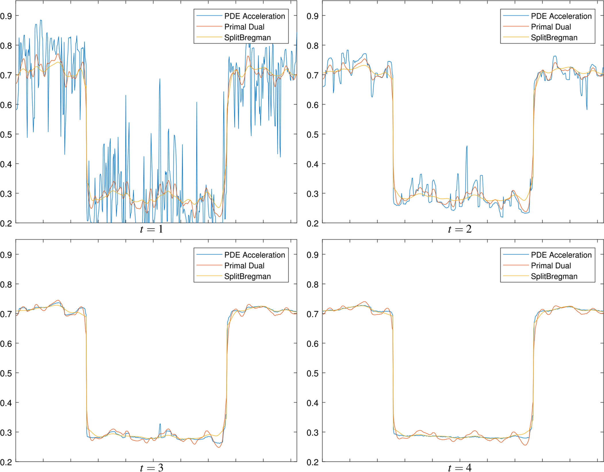
Comparison of PDE acceleration, primal–dual, and split Bregman algorithms for denoising a noisy square image. A one-dimensional slice of the image is displayed at the same computation time for each algorithm
Fig. 7.

Comparison of flows generated by a PDE acceleration and b primal–dual for solving the TV restoration problem on the noisy square image. Notice the edges are better preserved in PDE acceleration earlier in the flow
In the example above, we took Δt = Δx/2 for simplicity. Corroborating our analysis in Sect. 4.5, this explicit numerical scheme (66) behaves stably in L∞ in our experiments, meaning the solutions remain bounded in L∞ for all time, even for larger time steps which still satisfy the necessary conditions (60), (61), (62) or (63). For such larger time steps, though, we find the flow does not fully converge, yet remains stable via the nonlinear effect discussed in Sect. 4.5, but instead tends to an oscillatory steady state. Figure 8 shows a snapshot of the steady state for various values of the time step Δt. For Δt ≤ Δx, the steady state is a reasonable denoising; hence, we choose Δt = Δx or Δt = Δx/2 in most of this paper. Note that this closely matches the suggested time step bound in (67) for a quantization level of 1/255, given the other parameters utilized here, which would come out to Δt ≤ 1.189Δx.
Fig. 8.

Comparison of steady-state solutions for denoising the 2D noisy square for different time steps in PDE acceleration. The scheme is stable in L∞ for a variety of time steps though we observe Δt ≤ Δx is required to ensure the solution is a reasonable denoising
Figures 9, 10, and 11 compare the energy decay against CPU time for denoising the Lenna image with PDE acceleration, primal–dual, and split Bregman algorithms. The noise is additive zero mean Gaussian noise with standard deviation σ = 0.1, and the images take values in the interval [0, 1]. We note in Figs. 12 and 13 that PDE acceleration appears to yield a better quality image for the same energy level compared to primal–dual.
Fig. 9.

Comparison of logarithm of total energy versus CPU time for denoising the full 512×512 Lenna image with PDE acceleration, primal–dual, and split Bregman. We used the optimal damping from the linear analysis
Fig. 10.

Comparison of logarithm of TV seminorm energy versus CPU time for denoising the full 512 × 512 Lenna image with PDE acceleration, primal–dual, and split Bregman
Fig. 11.

Comparison of fidelity energy versus CPU time for denoising the full 512 × 512 Lenna image with PDE acceleration, primal–dual, and split Bregman
Fig. 12.

Comparison of PDE acceleration, primal–dual, and split Bregman for TV restoration of a noisy Lenna image with λ = 1000. Each algorithm was run for 150 iterations, which took 2.7s for PDE acceleration, 3.3s for primal–dual, and 28s for split Bregman
Fig. 13.

Comparison of PDE acceleration, primal–dual, and split Bregman for TV restoration of a noisy Lenna image with λ = 7000. Each algorithm was run for 50 iterations, which took 0.85s for PDE acceleration, 1.12s for primal–dual, and 10.4s for split Bregman
5.5. Variable Damping
We now give further considerations to variable damping. In Fig. 14, we show the initial condition and final converged result for five separate damping experiments. Note that the final result remains the same regardless of the damping coefficient that is chosen for a. From the linear analysis in (16) and our choice of λ = 1000 and β = 1 for the two tuning parameters, we have giving an optimal damping of 63.6. In Fig. 15, we compare an optimally damped system to a below optimal, above optimal, Nesterov, and critically damped system. The damping coefficients and convergence times in iterations are given in Table 2. The below optimal and above optimal are each one order of magnitude away from the optimal damping, respectively, and the critical damping is the point at which the second-order accelerated scheme is equivalent to gradient descent, i.e., the point at which the damping completely cancels out the momentum leaving only a first-order descent for the PDE. While the optimal damping will always give the fastest convergence for the PDE, if one is uncertain of the optimal damping, then using a greater than optimally damped but less than critically damped system will yield reasonable performance. While the Nesterov damping does converge faster than the above optimally damped example in Fig. 15, the increasing damping as a function of time will yield degraded performance and would likely necessitate an additional stopping criterion. Although the below optimally damped system is initially faster than the optimally damped system, it is subject to large oscillations in energy which while they do converge greatly slows down the final convergence time.
Fig. 14.

Initial (a) and final (b) condition of denoising experiment with variable damping. Note the final result does not change only the number of iterations required
Fig. 15.

Convergence experiment with variable damping for a Beltrami regularizer. Initial condition and converged result are given in Fig. 14
Table 2.
Coefficients and converge times of damping experiments for a 512 × 512 noisy Lena image
| Damping | Below optimal | Optimal | Above optimal | Nesterov | Critical | |||||
|---|---|---|---|---|---|---|---|---|---|---|
| a | Iterations | a | Iterations | a | Iterations | a | Iterations | a | Iterations | |
| λ = 1000, β2 = 1 | 6.36 | 1000 | 63.6 | 100 | 636 | 400 | 3/t | 250 | 1446 | 1000 |
6. Conclusion
We employed the novel framework of PDE acceleration, based on momentum methods such as Nesterov and Polyak’s heavy ball method, to calculus of variation problems defined for general functions on . The result was a very general set of accelerated PDEs whose simple discretizations efficiently solve the resulting class of optimization problems. We further analyzed their use in regularized inversion problems, where gradient descent diffusion equations get replaced by nonlinear wave equations within the framework of PDE acceleration, with far more generous discrete time step conditions.
We presented results of experiments on image processing problems including Beltrami regularized denoising and inpainting, and total variation (TV) regularized denoising and deblurring. In all cases, we can achieve state-of-the-art results with very simple algorithms; indeed, the PDE acceleration update is a simple explicit forward Euler update of a nonlinear wave equation. Future work will focus on problems such as TV inpainting, where there is no fidelity, how to choose the damping parameter adaptively to further accelerate convergence, and applications to other problems in computer vision, such as Chan–Vese active contours [11].
Acknowledgments
J. Calder was supported by NSF-DMS Grant 1713691, and A. Yezzi was supported by NSF-CCF Grant 1526848 and ARO W911NF-18-1-0281, and NIH R01 HL143350.
Biographies

Minas Benyamin is an Electrical Engineering Ph.D. student at the Georgia Institute of Technology. He graduated with his bachelors in Electrical Engineering from the University of Maryland College Park in May 2016 and received his Masters in Electrical Engineering from the Georgia Institute of Technology in May 2018.

Jeff Calder is an assistant professor of mathematics at the University of Minnesota. He obtained his Ph.D. in Applied Mathematics from the University of Michigan in 2014, and a B.Sc. in Mathematics and Engineering and M.Sc. in Mathematics from Queen’s University in 2008 and 2010, respectively. From 2014 to 2016, he was a Morrey Assistant Professor at the University of California, Berkeley, and he joined the faculty in the School of Mathematics at the University of Minnesota as an assistant professor in 2016. Dr. Calder’s research interests lie at the intersection of partial differential equations (PDE), applied probability, and machine learning, and he is interested in applications in image processing and computer vision. Some central themes of his research involve PDE continuum limits for discrete problems in machine learning.

Ganesh Sundaramoorthi is currently Principal Research Scientist at United Technologies Research Center in East Hartford, CT, USA. His research throughout his career has been in computer vision and optimization, both in theory and applications. He has applied some of his research to develop technology for video analysis, seismic image analysis, electron microscopy images, and medical (MRI & CT) images. He was on the faculty of KAUST within the Electrical Engineering and Applied Mathematics and Computational Science departments between 2011 and 2018. He was a postdoctoral research associate at the University of California, Los Angeles from 2008 to 2011. His PhD is in Electrical and Computer Engineering from the Georgia Institute of Technology in Atlanta, GA, USA in 2008. His PhD developed shape optimization methods for computer vision that aided in technology for video tracking, and medical image analysis. His Bachelor’s degrees were in Computer Engineering and Applied Mathematics, which he earned in 2003, also from Georgia Tech. He has served as Area Chair for the leading computer vision conferences, including IEEE Conference on Computer Vision and Pattern Recognition (CVPR) and IEEE International Conference on Computer Vision (ICCV).

Anthony Yezzi holds the position of Julian Hightower Chair Professor within the School of Electrical and Comptuer Engineering at Georgia Institute of Technology where he directs the Laboratory for Computational Computer Vision. He has over twenty years of research experience in shape optimization via geometric partial differential equations. He obtained his Ph.D. in Electrical Engineering in December 1997 from the University of Minnesota with a minor in mathematics. After completing a postdoctoral research appointment at Massachusetts Institute of Technology, he joined the faculty at Georgia Tech in August 1999. Dr. Yezzi’s research lies primarily within the fields of image processing and computer vision with a particular emphasis on medical imaging and 3D surface reconstruction. He has consulted for a number of companies including GE, 3M, MZA, Philips, Picker, and VTI. His work spans a wide range of image processing and vision problems including image denoising, edge-detection, segmentation, shape analysis, multi-frame stereo reconstruction, visual tracking, and registration. Some central themes of his research include curve and surface evolution, differential geometry, partial differential equations, and shape optimization.
Footnotes
Publisher’s Note Springer Nature remains neutral with regard to jurisdictional claims in published maps and institutional affiliations.
Nonconvex problems are also widely used, see, e.g., [17].
Primal–dual and split Bregman also avoid the non-smoothness of the L1 norm, which is an issue in descent-based approaches and often requires some form of regularization.
Acceleration can also be used in the sense that in Nesterov acceleration the gradient is forward looking and computed ahead of the current state [16]. The semi-implicit case which is an extension from the ODE framework of Nesterov uses a similar look ahead for its update scheme.
A discrete version of what is often called the symbol of the underlying linear differential operator that is being approximated.
For completeness, the first-order backward difference scheme can also be written recursively in the form Δun = (1 − aΔt) Δun−1−Δt2∇En.
References
- 1.Attouch H, Goudou X, Redont P: The heavy ball with friction method, I. The continuous dynamical system: global exploration of the local minima of a real-valued function by asymptotic analysis of a dissipative dynamical system. Commun. Contemp. Math 2(01), 1–34 (2000) [Google Scholar]
- 2.Aubert G, Kornprobst P: Mathematical Problems in Image Processing: Partial Differential Equations and the Calculus of Variations. Springer, New York: (2006) [Google Scholar]
- 3.Bähr M, Breuß M, Wunderlich R: Fast explicit diffusion for long-time integration of parabolic problems. In: AIP Conference Proceedings, vol. 1863, p. 410002. AIP Publishing; (2017) [Google Scholar]
- 4.Bottou L: Large-scale machine learning with stochastic gradient descent. In: Proceedings of COMPSTAT’2010, pp. 177–186. Springer; (2010) [Google Scholar]
- 5.Boyd S, Vandenberghe L: Convex Optimization. Cambridge University Press, Cambridge: (2004) [Google Scholar]
- 6.Baravdish G, Svensson O, Gulliksson M, Zhang Y: A damped flow for image denoising. arXiv preprint arXiv:1806.06732 (2018)
- 7.Calatroni L, Chambolle A: Backtracking strategies for accelerated descent methods with smooth composite objectives. arXiv preprint arXiv:1709.09004 (2017)
- 8.Calder J, Yezzi A: An accelerated PDE framework for efficient solutions of obstacle problems. Preprint (2018) [Google Scholar]
- 9.Chambolle A, Pock T: A first-order primal–dual algorithm for convex problems with applications to imaging. J. Math. Imaging Vis 40(1), 120–145 (2011) [Google Scholar]
- 10.Chambolle A, Pock T: An introduction to continuous optimization for imaging. Acta Numer. 25, 161–319 (2016) [Google Scholar]
- 11.Chan TF, Vese LA: Active contours without edges. IEEE Trans. Image Process 10(2), 266–277 (2001) [DOI] [PubMed] [Google Scholar]
- 12.Goldstein T, Osher S: The split Bregman method for l1-regularized problems. SIAM J. Imaging Sci 2(2), 323–343 (2009) [Google Scholar]
- 13.Goudou X, Munier J: The gradient and heavy ball with friction dynamical systems: the quasiconvex case. Math. Program 116(1–2), 173–191 (2009) [Google Scholar]
- 14.Hafner D, Ochs P, Weickert J, Reißel M, Grewenig S: FSI schemes: fast semi-iterative solvers for PDEs and optimisation methods. In: German Conference on Pattern Recognition, pp. 91–102. Springer; (2016) [Google Scholar]
- 15.Kimmel R, Malladi R, Sochen N: Image processing via the beltrami operator. In: Asian Conference on Computer Vision, pp. 574–581. Springer; (1998) [Google Scholar]
- 16.Nesterov Y: A method of solving a convex programming problem with convergence rate o (1/k2). Sov. Math. Dokl 27, 372–376 (1983) [Google Scholar]
- 17.Perona P, Malik J: Scale-space and edge detection using anisotropic diffusion. IEEE Trans. Pattern Anal. Mach. Intell 12(7), 629–639 (1990) [Google Scholar]
- 18.Polyak BT: Some methods of speeding up the convergence of iteration methods. USSR Comput. Math. Math. Phys 4(5), 1–17 (1964) [Google Scholar]
- 19.Ratner V, Zeevi YY: Image enhancement using elastic manifolds. In: 14th International Conference on Image Analysis and Processing (ICIAP 2007), pp. 769–774 (2007). 10.1109/ICIAP.2007.4362869 [DOI] [Google Scholar]
- 20.Rudin LI, Osher S, Fatemi E: Nonlinear total variation based noise removal algorithms. Phys. D Nonlinear Phenom 60(1–4), 259–268 (1992) [Google Scholar]
- 21.Sochen N, Kimmel R, Malladi R: A general framework for low level vision. IEEE Trans. Image Process 7(3), 310–318 (1998) [DOI] [PubMed] [Google Scholar]
- 22.Su W, Boyd S, Candes E: A differential equation for modeling Nesterov’s accelerated gradient method: theory and insights. In: Advances in Neural Information Processing Systems, pp. 2510–2518 (2014) [Google Scholar]
- 23.Sundaramoorthi G, Yezzi A: Accelerated optimization in the PDE framework: formulations for the manifold of diffeomorphisms. arXiv:1804.02307 (2018) [DOI] [PMC free article] [PubMed]
- 24.Sundaramoorthi G, Yezzi A: Variational PDE’s for acceleration on manifolds and applications to diffeomorphisms. In: Neural Information Processing Systems (2018) [Google Scholar]
- 25.Sutskever I, Martens J, Dahl G, Hinton G: On the importance of initialization and momentum in deep learning. In: International Conference on Machine Learning, pp. 1139–1147 (2013) [Google Scholar]
- 26.Trefethen LN: Finite difference and spectral methods for ordinary and partial differential equations. unpublished text, available at http://web.comlab.ox.ac.uk/oucl/work/nick.trefethen/pdetext.html (1996)
- 27.Ward C, Whitaker N, Kevrekidis I, Kevrekidis P: A toolkit for steady states of nonlinear wave equations: continuous time Nesterov and exponential time differencing schemes. arXiv:1710.05047 (2017)
- 28.Weickert J, Grewenig S, Schroers C, Bruhn A: Cyclic schemes for PDE-based image analysis. Int. J. Comput. Vis 118(3), 275–299 (2016) [Google Scholar]
- 29.Wibisono A, Wilson AC, Jordan MI: A variational perspective on accelerated methods in optimization. Proc. Natl. Acad. Sci 113(47), E7351–E7358 (2016) [DOI] [PMC free article] [PubMed] [Google Scholar]
- 30.Yezzi A, Sundaramoorthi G: Accelerated optimization in the PDE framework: formulations for the active contour case. arXiv:1711.09867 (2017) [DOI] [PMC free article] [PubMed]
- 31.Yezzi A, Sundaramoorthi G, Benyamin M: PDE acceleration for active contours. In: Proceedings of the IEEE Conference on Computer Vision and Pattern Recognition (2019) [Google Scholar]
- 32.Zosso D, Bustin A: A primal–dual projected gradient algorithm for efficient beltrami regularization. UCLA CAM Report 14–52 (2014). [Google Scholar]