

Abstract
This paper reports on a fully miniaturized brain-spinal interface (BSI) system for closed-loop cortically-controlled intraspinal microstimulation (ISMS). Fabricated in AMS 0.35μm two-poly four-metal complementary metal-oxide-semiconductor (CMOS) technology, this system-on-chip (SoC) measures ~ 3.46mm × 3.46mm and incorporates two identical 4-channel modules, each comprising a spike-recording front-end, embedded digital signal processing (DSP) unit, and programmable stimulating back-end. The DSP unit is capable of generating multichannel trigger signals for a wide array of ISMS triggering patterns based on real-time discrimination of a programmable number of intracortical neural spikes within a pre-specified time-bin duration via thresholding and user-adjustable time-amplitude windowing. The system is validated experimentally using an anesthetized rat model of a spinal cord contusion injury at the T8 level. Multichannel neural spikes are recorded from the cerebral cortex and converted in real time into electrical stimuli delivered to the lumbar spinal cord below the level of the injury, resulting in distinct patterns of hindlimb muscle activation.
Keywords: Brain-spinal interface, closed-loop neuromodulation, closed-loop neuroprosthesis, intraspinal microstimulation, neural recording, spike discrimination, spinal cord injury, system-on-chip
1. Introduction
Spinal cord injury (SCI) is among the most debilitating neural injuries that can be sustained. SCI is typically caused by a traumatic blow to the spine, interrupting signal transmission between the brain and muscles and resulting in an impairment of every body part that receives innervation below the level of the injury. While the focus of the pharmaceutical industry has been on the development of drugs used in acute stages after injury, purportedly to help stabilize the spinal cord, rescue vulnerable neurons from cell-death cascades, and minimize further injury, few options are available beyond the first few hours to days. Attempts to re-grow severed spinal cord fibers across the lesion to restore the neural circuits to their pre-injury state have been very challenging. While stem cell therapy has shown significant promise, clinical translation is still many years away. Hence, the development of advanced neuroprosthetics for restoration of function after SCI has garnered much attention over the past several years as one of the most rapidly growing and potentially influential directions for neuroscience and neuroengineering research [1]-[5].
Existing brain-machine interfaces (BMIs) have been most successful in using artificially generated electrical signals to mimic sensory inputs to the nervous system [6]. New approaches are also being developed that use the brain’s intrinsic signals as input commands for controlling external devices. For example, after SCI, it is now possible to use motor cortex command signals for directly manipulating a prosthetic limb [7], [8]. More recently, these approaches have also been extended to a closed-loop paradigm for real-time cortical control of the paralyzed limb itself in a human subject with cervical SCI [9].
In fact, the latest embodiments of implantable BMIs simultaneously feature the three functions of neural recording, embedded signal processing, and neural stimulation [10]-[15]. Operating in closed-loop fashion and acting as an artificial neural link, these devices reconnect two distinct regions of the cerebral cortex [13]-[15], as well as one region of the cerebral cortex to muscles [9], [16], [17] or the spinal cord [1], [2], [4], [5], [18], [19] in real time.
The majority of these closed-loop neuroprosthetic devices operate in a control mode by first deciphering the subject’s intent for volitional control of its body from the recorded cortical activity and then by activating the target to produce a motion [1], [4], [5], [9]. However, devising and implementing the related signal-processing and control algorithms is nontrivial and significant learning by the subject might be needed to complete the task depending on its complexity. Moreover, by virtue of the fact that control-mode approaches replace the pathways lost due to an injury, such neuroprosthetic devices need to remain functional throughout the subject’s lifetime, facing additional challenges with regard to chronic implantation.
Since the neural circuits above and below the injury level generally remain intact after an SCI [19] and a substantial number of descending fibers typically survive spinal injuries, it might be possible to employ closed-loop neuroprosthetic devices in a conditioning mode instead. In fact, closed-loop conditioning-mode approaches have been employed for functional reorganization in an intact nervous system [18], [20], and for facilitating synaptic connections and restoring function in an injured nervous system [21], [22]. Enhancement of descending spinal cord fiber tracts such as the corticospinal (CS) tract, through the use of neurophysiological principles of synaptic facilitation, may allow improved motor function within a relatively short time frame. CS synaptic facilitation could use the same cortical signals as control-mode approaches for triggering spinal cord stimulation, but would precisely dictate the timing of stimulation in one or more target regions of the spinal cord with a time delay with respect to cortical spike activity [20], [22].
This paper reports on the design, development, and validation of a brain-spinal interface (BSI) system-on-chip (SoC) for closed-loop intraspinal microstimulation (ISMS), as conceptually shown in Fig. 1. This system successfully converts in real time cortical spike activity into electrical stimuli delivered to the lumbar spinal cord below the level of the injury. This SoC is envisioned to be used in future conditioning-mode experiments designed to alter the synaptic efficacy of descending spinal cord connections, especially the CS tract. While future systems will likely have to support a wide variety of operation scenarios, in the present paper, we validate a few of the most essential ISMS triggering patterns using an anesthetized rat model of contusion injury to the thoracic spinal cord.
Figure 1:
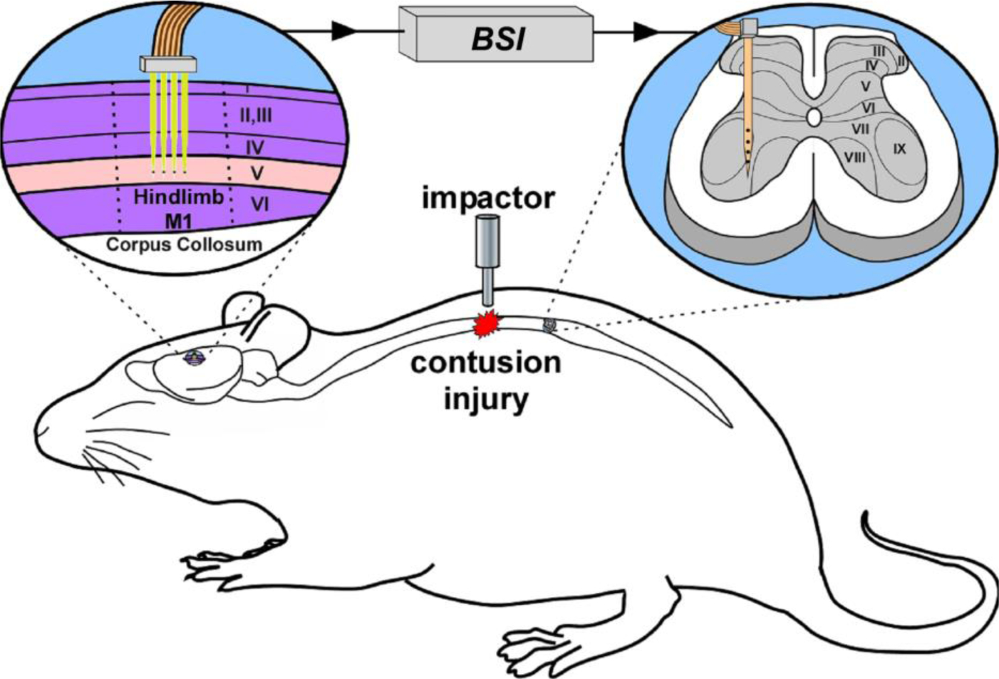
Conceptual illustration of a BSI system to enhance synaptic efficacy in CS pathways spared after an SCI.
2. ISMS Trigger-Generation Strategy
Fig. 2 illustrates the strategy of the BSI system for translating intracortical neural spike activity into multichannel ISMS triggers in real time [23]. For simplicity, Fig. 2 shows a representative case involving two recording and four stimulating channels in a sequential triggering mode, but the BSI system can support up to eight recording and stimulating channels along with a wide range of ISMS triggering patterns.
Figure 2:
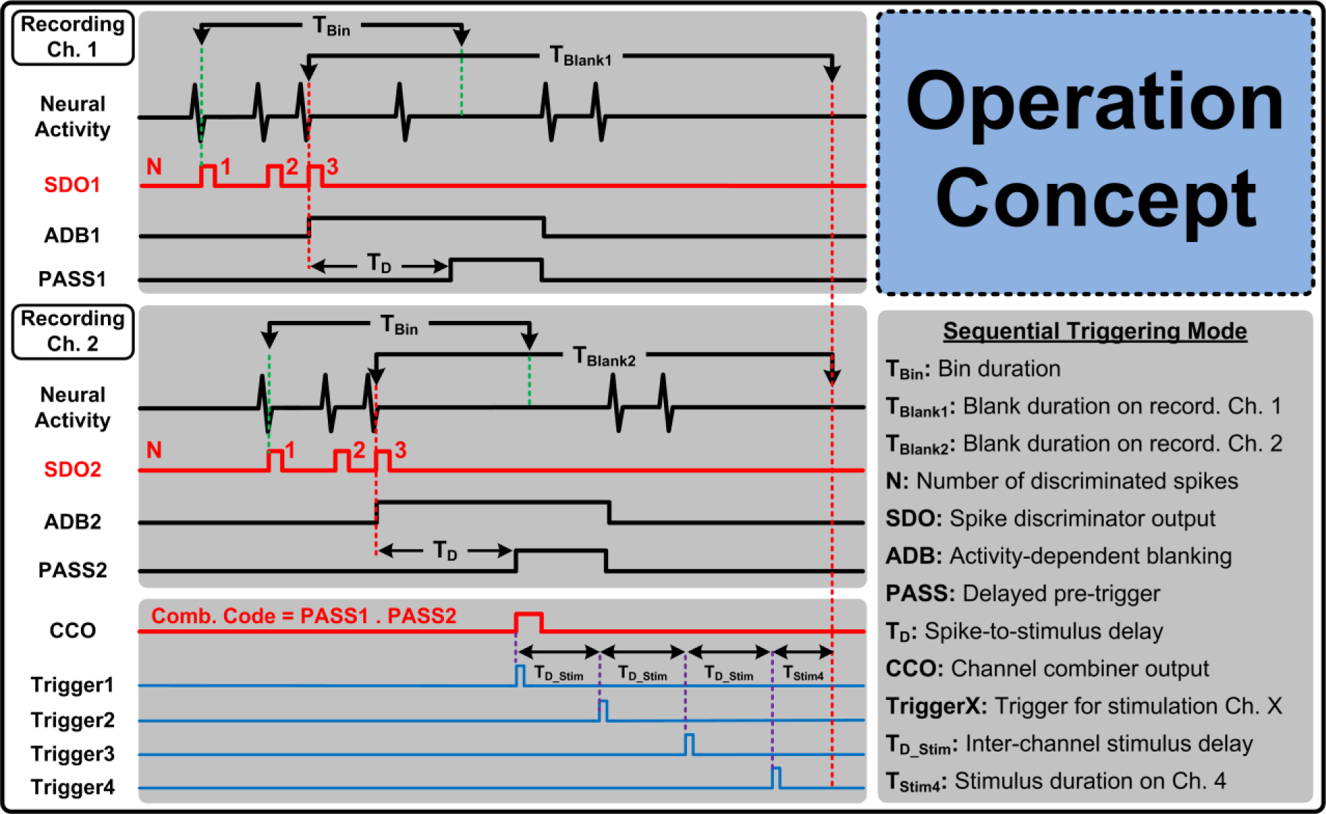
BSI system strategy for multichannel translation of intracortical neural spikes to ISMS trigger signals.
The BSI system discriminates each intracortical neural spike event from noise and other artifacts, and activates a spike discriminator output signal, SDO, on each recording channel accordingly. Once a pre-specified number of neural spikes, N, are discriminated on each recording channel within a pre-specified time-bin duration, TBin, the system activates a PASS signal on each recording channel after a programmable time delay, TD, following the discrimination of the last spike. ISMS triggers, Trigger1~4, are then generated based on any logic combination of the PASS signals. For example, Fig. 2 shows a representative case when sequential ISMS triggering is generated with user-adjustable inter-channel stimulus delay of TD_Stim, when N = 3 neural spikes are simultaneously discriminated on both recording channels. Hence, trigger generation is based on the logic AND function of the two PASS signals.
The BSI system also supports a paired sequential triggering mode in which simultaneous triggering occurs on the first two stimulating channels (Trigger1,2) followed by simultaneous triggering on the next two channels (Trigger3,4) after a delay of 3 × TD_Stim. Setting TD_Stim to zero results in simultaneous triggering on all four stimulating channels. For operation versatility, an individual triggering mode is also supported in which each trigger signal itself (i.e., TriggerX) is independently defined as a logic combination of the PASS signals using a unique 16b combination code for each stimulating channel.
Finally, the BSI system employs novel blanking schemes to disregard the input neural data on some or even all of the recording channels for specific time periods indicated as TBlank in Fig. 2. The rationale and implementation details of these blanking schemes for various ISMS triggering modes are further explained in Section 5.
3. BSI System Architecture
Fig. 3 illustrates the BSI system architecture and its operation timing. The system incorporates two identical 4-channel modules, with each module comprising a spike-recording front-end, digital signal processing (DSP) unit, and stimulating back-end. Each recording channel amplifies, bandpass filters, and digitizes the extracellular neural spikes. The DSP unit discriminates individual neural spikes on each recording channel in real time using thresholding and programmable time-amplitude windowing. Next, as stated previously, a decision maker within the DSP unit generates the ISMS trigger signals based on a programmable number of neural spikes discriminated on each recording channel and various other adjustable settings.
Figure 3:
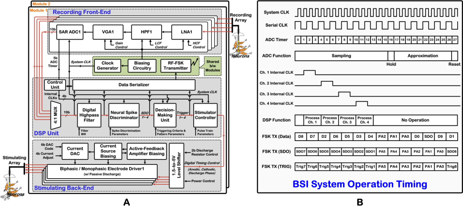
A) BSI system architecture. B) Operation timing of the BSI system for one analog-to-digital conversion cycle.
A stimulator controller uses the trigger signals as input and generates the requisite timing control signals for the stimulating back-end to deliver a train of ISMS current pulses via the stimulating array. This block also controls current pulse parameters such as duration as well as frequency and number within an ISMS train. The four channels of the stimulating back-end share a 6b current-mode DAC with 4b current-adjust mechanism for programming the current pulse amplitudes in the range of 0 to ~ 100μA (anodic) and 33.3μA (cathodic).
Moreover, the BSI system incorporates a clock generator, bias circuitry, as well as FSK transmitter (TX) that are all shared between the two modules. The clock generator provides the BSI system clock at nominal frequency of 1MHz with 5b programmability in frequency. The FSK TX operates at ~ 433MHz in three different modes, as illustrated in the operation timing in Fig. 3B. In one mode, this block transmits the 10b-digitized raw or highpass-filtered recorded data on one selected channel along with its corresponding SDO signal. In this mode, a 3b preamble is also scrambled within the bit-stream for synchronizing the TX with an outside receiver. In the other two modes, this block transmits either the SDO or the trigger signals on both modules of the SoC together with a 6b synchronizing preamble.
As shown in the system operation timing in Fig. 3B, each conversion cycle of the ADC takes 28μs, sampling the amplified/filtered neural spikes at ~ 35.7kSa/s/ch. Utilizing the 1MHz system clock and 5b ADC timer information from the recording front-end, the DSP unit generates an internal clock for each recording channel in order to manage the internal operations. Each of the internal clock signals lasts for two cycles of the 1MHz system clock, with one additional clock cycle as delay between the channels. Hence, the processing of each data channel by the DSP unit takes only three system clock cycles. Finally, an embedded data serializer in the DSP unit extracts a 500kHz serial clock from the 1MHz system clock to send the raw/filtered recorded data as well as the SDO and trigger signals to the FSK TX and/or input-output pads.
4. DSP Unit Architecture
The recording front-end and stimulating back-end circuitry leverages our previous silicon-verified designs for interfacing with the cortex [15], [24] and spinal cord [25], respectively. Hence, for brevity, this section focuses on a more detailed description of the DSP unit architecture and operation. Fig. 3A shows a simplified architecture of the DSP unit in each module. The core blocks include a digital highpass filter (HPF), neural spike discriminator, and decision-making circuitry, whereas auxiliary blocks include a control unit, data serializer, and stimulator controller. The core blocks of the DSP unit are described in more details below.
4.1. Digital HPF
Fig. 4 depicts a more detailed architecture of the 1st-order infinite impulse response (IIR) digital HPF, which removes any residual dc offsets or low-frequency noise/artifacts from the multiplexed input neural data. The filter transfer function is expressed as:
| (1) |
where factor K controls the filter bandwidth. With K equal to 1/16 or 1/8, the filter bandwidth can be set to be 366Hz or 756Hz, respectively, given a 1MHz system clock. Moreover, the HPF coefficients are chosen so that the filtering is performed only with arithmetic shifts, subtraction, and addition, obviating the use of power-hungry multiplier and divider stages.
Figure 4:
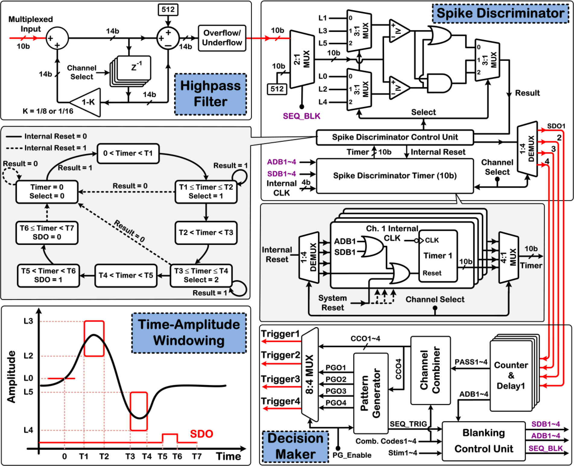
Architecture of the digital HPF, neural spike discriminator employing thresholding and time-amplitude windowing (bottom left), and decision maker of the DSP unit.
4.2. Neural Spike Discriminator
As shown in the bottom left corner of Fig. 4, the DSP unit employs thresholding and two user-adjustable time-amplitude windows for real-time neural spike discrimination. If the signal waveform crosses a user-positioned threshold level, L0, the spike discriminator is activated to check whether the signal waveform subsequently passes through both time-amplitude windows (solid red boxes). A negative threshold level, L1 (not shown), is used to discriminate waveforms with reverse polarity. If a spike event is accepted on any recording channel, the corresponding SDO signal is activated to flag the location of the discriminated neural spike in the recorded data and for the decision-making circuitry to subsequently generate the ISMS trigger signals. The timing parameters T1~4 (8b) and T5~7 (10b) are programmable in steps of 28μs, with maximum values of ~ 7.2ms and 28.6ms, respectively.
Fig. 4 also depicts the finite-state machine (FSM) diagram of the control unit of the neural spike discriminator, as well as the architecture of its timer block. For processing the data on each recording channel, the corresponding 10b timer information is selected and sent to the control unit. The timer information of each recording channel can be individually reset either internally or externally via the system reset signal, or via the blanking-related signals, as explained in more details in Section 5.
4.3. Decision-Making Unit
The decision-making unit is in charge of generating the four ISMS trigger signals for either the individual or sequential stimulus-triggering mode based on the received SDO signals as input and various user-defined settings. Specifically, counter & delay units within the decision maker count a programmable number of discriminated neural spikes (N ≤ 15) within a user-adjustable time-bin duration, TBin ≤ ~ 0.5s in steps of 56μs, and generate the PASS signal for each recording channel with a 10b-programmable delay, TD ≤ ~ 28.6ms in steps of 28μs, following the discrimination of the last spike. The four trigger signals are then generated based on the desired stimulus-triggering mode, which is selected by an 8:4 multiplexer at the decision maker output.
For ISMS triggering in individual mode, a channel combiner block generates each trigger signal, TriggerX, independently as a logic combination of the PASS signals using a unique 16b combination code for each stimulating channel. For ISMS triggering in the sequential mode, a pattern generator block generates the four trigger signals with a programmable constant inter-channel stimulus delay, TD_Stim ≤ ~ 1s in steps of 56μs.
To save in the number of programming and control bits for the BSI system parameter register, the pattern generator uses the same 16b combination code dedicated to the stimulating channel 4 in the individual triggering scenario to define the criteria for sequential triggering based on the PASS signals.
5. Blanking Schemes
As briefly stated in Section 2, the BSI system features blanking to disregard the input neural data on some or even all of the recording channels for specific periods of time. These blanking schemes ensure that stimulus artifacts, if present in the BSI system, will not lead to false-triggering. Moreover, since neural spikes can occur asynchronously at any time during the BSI system operation (e.g., during a period of stimulation), the blanking schemes provide a mechanism to prevent unwanted ISMS triggering during a period of stimulation, and to keep track of the trigger-generating spikes in any post hoc analysis of spike-stimulus pairs. Different blanking schemes for individual and sequential triggering modes are implemented by a blanking control unit within the decision maker that provides additional inputs to the neural spike discriminator, as described in more details below.
5.1. Blanking Scheme for Individual Triggering
In the individual triggering mode, each trigger signal itself (i.e., TriggerX) is defined as a logic combination of the PASS signals using a unique 16b combination code for each stimulating channel. As a representative case, Fig. 5A illustrates the blanking scheme for individual triggering on stimulating channel 3, initiated when trigger-generation criteria are satisfied on recording channel 1 only. Once spike-discrimination criteria are satisfied on any recording channel, an activity-dependent blanking signal, ADB, is activated on that same channel that blanks its input data by resetting the timer information of the recording channel in the neural spike discriminator until the falling edge of the corresponding PASS signal arrives (see Fig. 2.)
Figure 5:
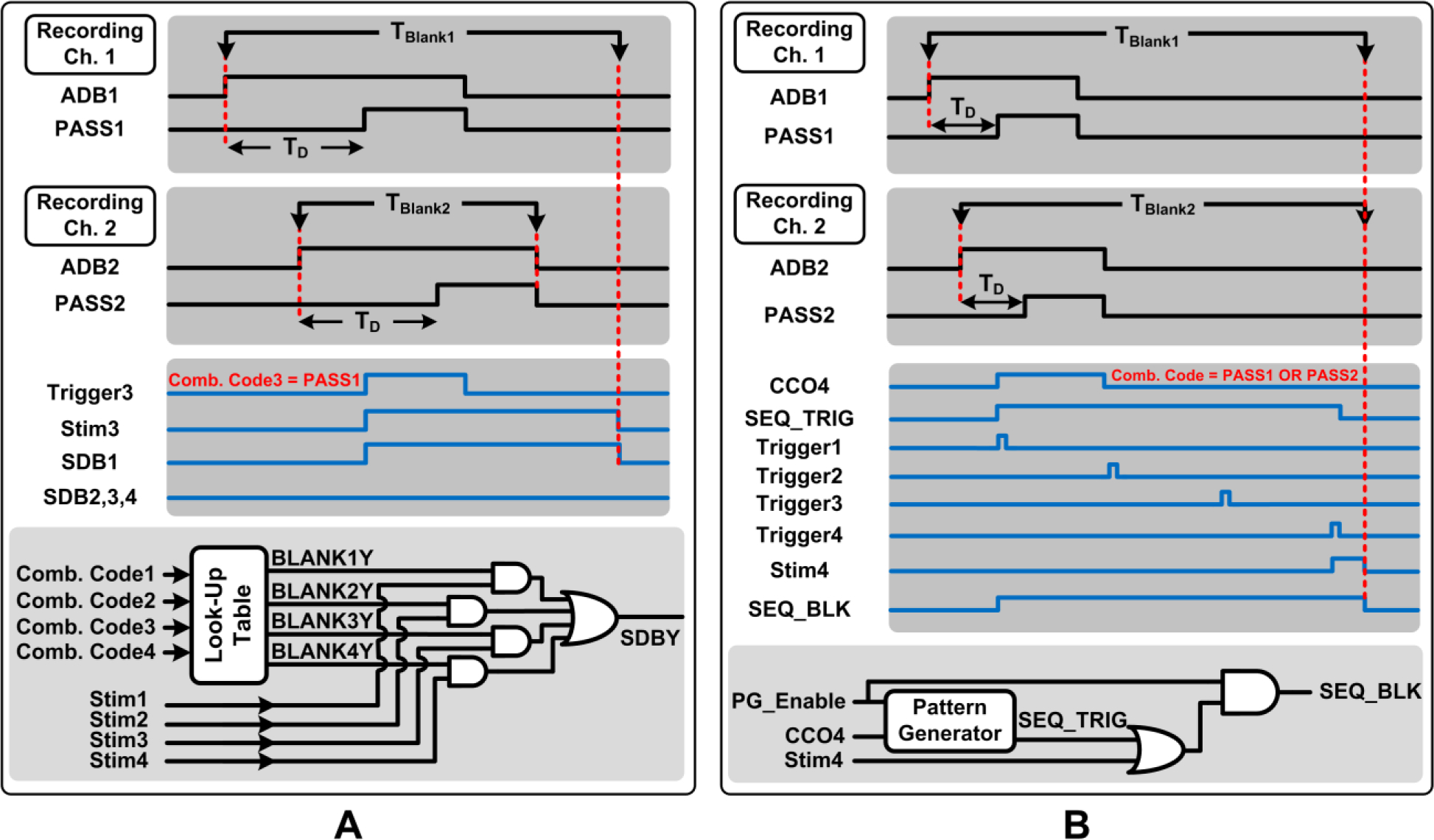
Illustration of the blanking scheme implemented by the blanking control unit of the decision maker for a representative case of A) individual triggering and B) sequential triggering.
However, depending upon the user-set combination code to define TriggerX, only a subset of the recording channels might be involved in ISMS trigger generation (e.g., recording Ch. 1, but not Ch. 2~4, in Fig. 5A). A second blanking signal, namely, stimulus-dependent blanking (SDB) is then employed to prolong the blanking duration only on those recording channels that are involved in ISMS trigger generation (i.e., recording Ch. 1 in Fig. 5A).
The blanking control unit incorporates a lookup table with the four user-defined combination codes as its input in order to generate a series of static command signals, BlankXY, at the output. In conjunction with StimX signals, which indicate the duration of stimulation on stimulating channel X and are provided via the stimulator controller of the DSP unit, the SDB1~4 signals are generated as shown in Fig. 5A (Y = 1~4). Specifically, in Fig. 5A, the Blank31 signal at the output of the lookup table and Stim3 signal will be active, whereas all other BlankXY and StimX signals will be inactive. This will activate the SDB1 signal only, and not SDB2~4. Hence, recording channel 1 will continue to be blanked beyond ADB1 until stimulation on channel 3 is ceased, while the other recording channels will not be blanked beyond the duration of their ADB signals. Similar to ADB signals, SDB signals perform blanking by resetting the timer information of the corresponding recording channels in the neural spike discriminator.
5.2. Blanking Scheme for Sequential Triggering
In the sequential triggering mode, all stimulating channels are engaged, which leads to maximum overall stimulus duration of several seconds per trigger depending on the user-set parameter TD_Stim. Hence, a blanking scheme is devised to disregard the input neural data on all recording channels until the end of stimulus duration. As a representative case, Fig. 5B illustrates the blanking scheme for sequential triggering, initiated when trigger-generation criteria are satisfied on recording channel 1 or 2. A sequential blanking output signal, SEQ_BLK, is generated by the blanking control unit that is active throughout the duration of sequential stimulation. This signal is then used to operate a 2:1 multiplexer at the front-end of the neural spike discriminator, as previously shown in Fig. 4. Specifically, the spike discriminator input is held at a constant level to disregard the multiplexed neural data. The internal clock signals of all recording channels are also de-activated in the DSP unit to save power during blanking.
6. Neurobiological Experiments
To test the ability of the BSI system to support various multichannel closed-loop operation scenarios, neurobiological tests were conducted using an anesthetized rat. These studies were performed in accordance with guidelines approved by the Institutional Animal Care and Use Committee (IACUC) at the University of Kansas Medical Center. The rat had received a contusion injury to the thoracic spinal cord at the T8 level three weeks prior to the neurobiological experiments, as shown in Fig. 6A. Details of the contusion procedure and consistency of outcome measures have been previously published [26]. As reported previously [27], SCI substantially alters the firing properties of single units across a wide swath of the cortex. Specifically, spontaneous firing rates are increased significantly for at least several weeks after injury. To develop neurophysiologically-relevant algorithms for cortically-controlled ISMS, it was necessary to conduct these studies using rats with spinal cord contusion injuries.
Figure 6:
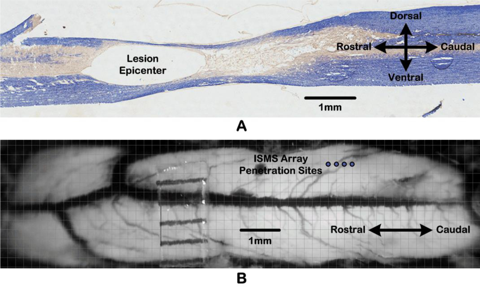
A) Micrograph of a sagittal section through thoracic spinal cord at the T8 level. B) Dorsal view of the lumbar spinal cord surface, showing penetration sites (blue circles) of the 4-shank ISMS microelectrode array.
Testing of the BSI system functionality was conducted after a second surgical procedure three weeks post-SCI. Specifically, a single-shank silicon microelectrode array with sixteen 703μm2 recording sites of iridium (average site impedance of 0.6MΩ at 1kHz) was implanted at a depth of 1,600μm in the whisker barrel field. The somatosensory barrel field was chosen for these particular experiments, as it allowed us to precisely control the timing of increased spike activity (above spontaneous spiking rates) via mechanical stimulation of the mystacial vibrissae of the anesthetized rat. Future studies to test the ability of conditioning-mode approaches to enhance synaptic efficacy of CS connections will utilize recordings from the hindlimb motor cortex of an ambulatory rat (see Fig. 1.)
Moreover, after performing a laminectomy on the T13-L1 vertebrae exposing lumbar segments of the spinal cord, a four-shank silicon microelectrode array with sixteen 1,250μm2 stimulating sites of iridium oxide (average site impedance of 30kΩ at 1kHz) was implanted in the lumbar cord. The four electrode shanks, which were 200μm apart, were positioned 0.8mm lateral to the midline blood vessel, as shown in Fig. 6B, and lowered to a depth of 2.274mm. Thus, while the stimulating electrode sites on each shank spanned a range of depths, the sites used in these particular experiments corresponded approximately to lamina VIII and IX, i.e., within the ventral spinal cord grey matter.
To record the electromyogram (EMG) signals evoked by ISMS, fine-wire electrodes were also implanted in three hindlimb muscles of the rat. Each EMG electrode consisted of two stainless steel wires, with the exposed implanted end of the wire (~ 1mm) folded back on itself (i.e., a hook electrode). EMG electrodes were inserted into the belly of each muscle with the aid of a 22-gauge hypodermic needle. For each EMG electrode pair, the wires were positioned ~ 5mm apart in each muscle. An additional ground lead was also placed into the base of the tail. EMG signals allowed us to validate the timing and efficacy of ISMS, as well as any differential muscle responses due to different locations of stimulating electrode sites within the spinal cord.
7. Experimental Results
The BSI SoC was fabricated in AMS 0.35μm 2P/4M CMOS, measuring ~ 3.46mm × 3.46mm including the bonding pads. Fig. 7 shows a micrograph of the fabricated chip. The electrical performance of each building block of the SoC was thoroughly characterized in benchtop tests prior to conducting neurobiological experiments. Table I tabulates the measured SoC electrical performance.
Figure 7:
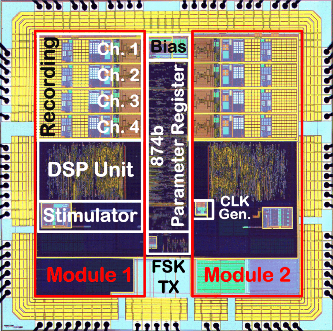
BSI SoC micrograph.
7.1. ISMS w/Individual Triggering from a Single Recording Channel
In our first experiment, the BSI system was programmed to generate individual ISMS triggers for stimulating on a single channel (channel 4) after real-time processing of the recorded neural data on a single recording channel (channel 1). The selected criteria for trigger generation were based on discriminating two neural spikes (N = 2) within a time-bin duration of < 0.5s, with TD set to 25ms. Furthermore, in this experiment, the BSI system delivered a single monophasic current pulse (15μA, 200μs) with passive discharge per ISMS trigger. Fig. 8 depicts the measured results from the BSI system. As can be seen in Fig. 8A–B, SDO1 signal correctly indicated the discrimination of two neural spikes upon which Trigger4 signal was generated 25ms after the second spike was discriminated. Note that the three stimulus artifacts in Fig. 8A, which were time-synchronized with the three Trigger4 signals in Fig. 8B, did not result in false-triggering due to the SDB-based blanking feature of the BSI system. Fig. 8C shows an expanded view of the discriminated spikes (in dark grey) that crossed the positive threshold level and subsequently passed through the two user-set time-amplitude windows. The signal waveforms in light grey were rejected by the BSI system for triggering purposes, as they did not satisfy all discrimination criteria at the same time. Finally, Fig. 8D depicts the fine-wire EMG signals recorded from three hindlimb muscles of the rat evoked by closed-loop cortically-controlled ISMS that was delivered to the lumbar spinal cord below the injury level. This indicated that the current pulse was effective in activating the firing of motor neurons at low current levels.
Figure 8:
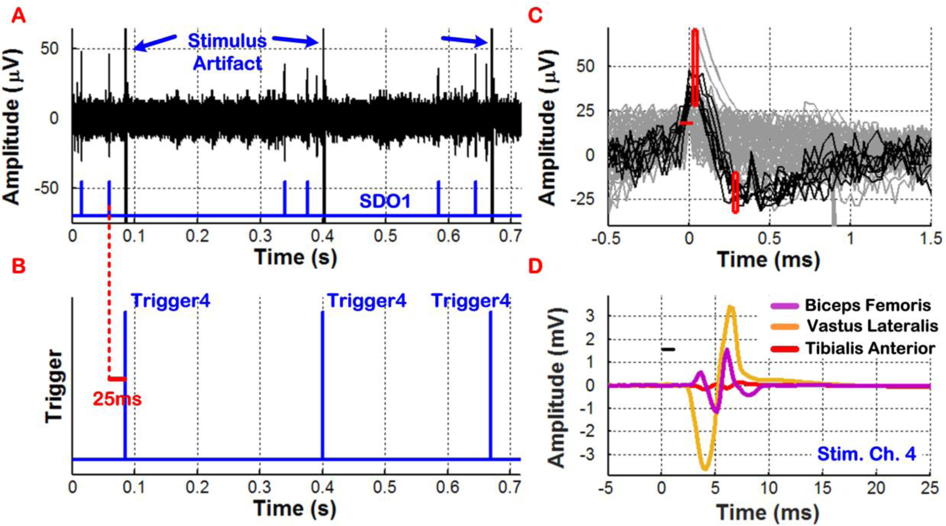
In vivo demonstration of real-time cortical control of ISMS in an SCI rat with individual triggering. ISMS was performed using a single current pulse on stimulating channel 4 and was triggered by neural spikes discriminated on recording channel 1. The ISMS current pulse with duration of ~ 1ms was applied at t = 0 and shown as a small black bar in plot D, which also depicts the EMG signals recorded from three hindlimb muscles of the rat that were evoked by ISMS.
7.2. ISMS w/Paired Sequential Triggering from a Single Recording Channel
In our second experiment, the BSI system was re-programmed to generate ISMS triggers upon discriminating three neural spikes (N = 3) within a time-bin duration of < 0.5s on recording channel 1. However, in this experiment, the BSI system was configured to support a paired sequential triggering scenario. Specifically, when the third neural spike was discriminated, ISMS triggers were generated for stimulating channels 1 and 2, followed by ISMS triggers for stimulating channels 3 and 4 after a 600ms delay. The TD and TD_Stim parameters were set to 20ms and 200ms, respectively. Moreover, the ISMS current pulse amplitude was slightly decreased from 15 to 10μA. Fig. 9 shows the measured results in this mode, verifying correct operation of the BSI system by generating Trigger1,2 and Trigger3,4 signals sequentially, when trigger-generation criteria were satisfied on recording channel 1. Distinct patterns of hindlimb muscle activation were also observed as a result of closed-loop cortically-controlled ISMS, as depicted in Fig. 9D–E. This experiment showed that multiple current pulses could be delivered in a preprogrammed fashion, following a single acceptance state for triggering.
Figure 9:
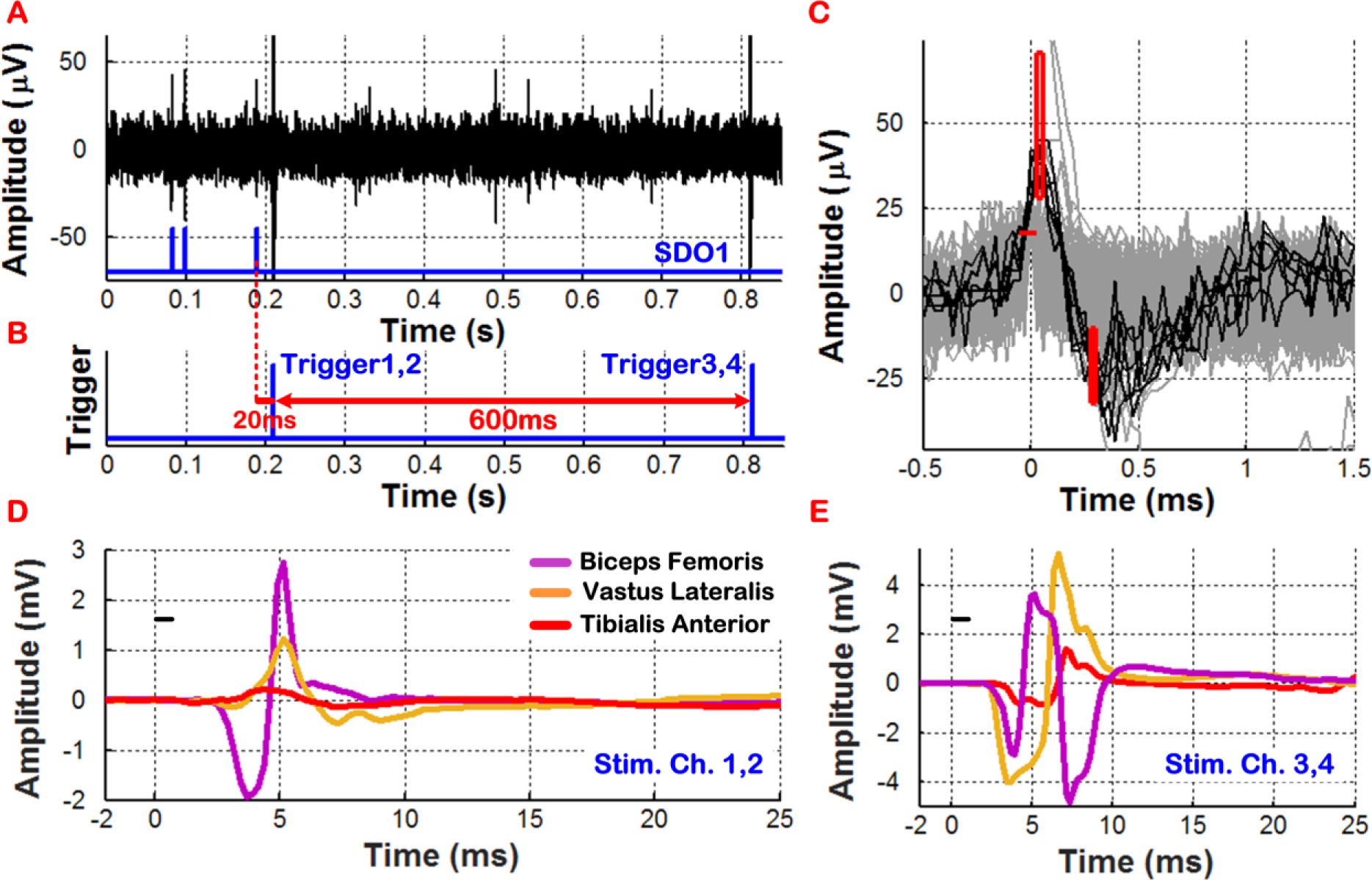
In vivo demonstration of real-time cortical control of ISMS in an SCI rat with paired sequential triggering. Triggered by neural spike activity on recording channel 1, ISMS was performed simultaneously on stimulating channels 1 and 2, followed by that on stimulating channels 3 and 4 after a delay of 600ms. Plots D and E show differentiated patterns of hindlimb muscle activation by cortically-controlled ISMS.
7.3. ISMS w/Sequential Triggering from a Combination of Multiple Recording Channels
Finally, the BSI system was programmed to generate ISMS triggers based on spike discrimination on multiple recording channels. Specifically, the criteria for trigger generation were based on discriminating two neural spikes (N = 2) within a time-bin duration of < 0.5s simultaneously on recording channels 1 and 4. The TD and TD_Stim parameters as well as the duration of PASS signals were selected to be 10ms, 220ms, 15ms, respectively. In this test, the BSI system was configured to support a sequential triggering case in which ISMS current pulses were delivered to stimulating channel 1, followed by channels 2, 3, and 4, each separated in time by 220ms.
Fig. 10A–C show the measurement results for a 1s window of neural activity on recording channels 1 and 4 in which four sequential triggers were generated when trigger-generation criteria were simultaneously satisfied on both recording channels (shortly after t = 0.2s). Fig. 10D–E show an expanded view of the discriminated neural spikes (in dark grey) that crossed the positive threshold level and subsequently passed through the two user-set time-amplitude windows. The signal waveforms in light grey were once again rejected by the BSI system for triggering purposes, as they did not satisfy all discrimination criteria. As seen in Fig. 10F–H, distinct patterns of hindlimb muscle activation were once again observed as a result of closed-loop cortically-controlled ISMS delivered to the lumbar spinal cord of the SCI rat below the injury level. Stimulation on channel 1 did not result in any muscle activation.
Figure 10:
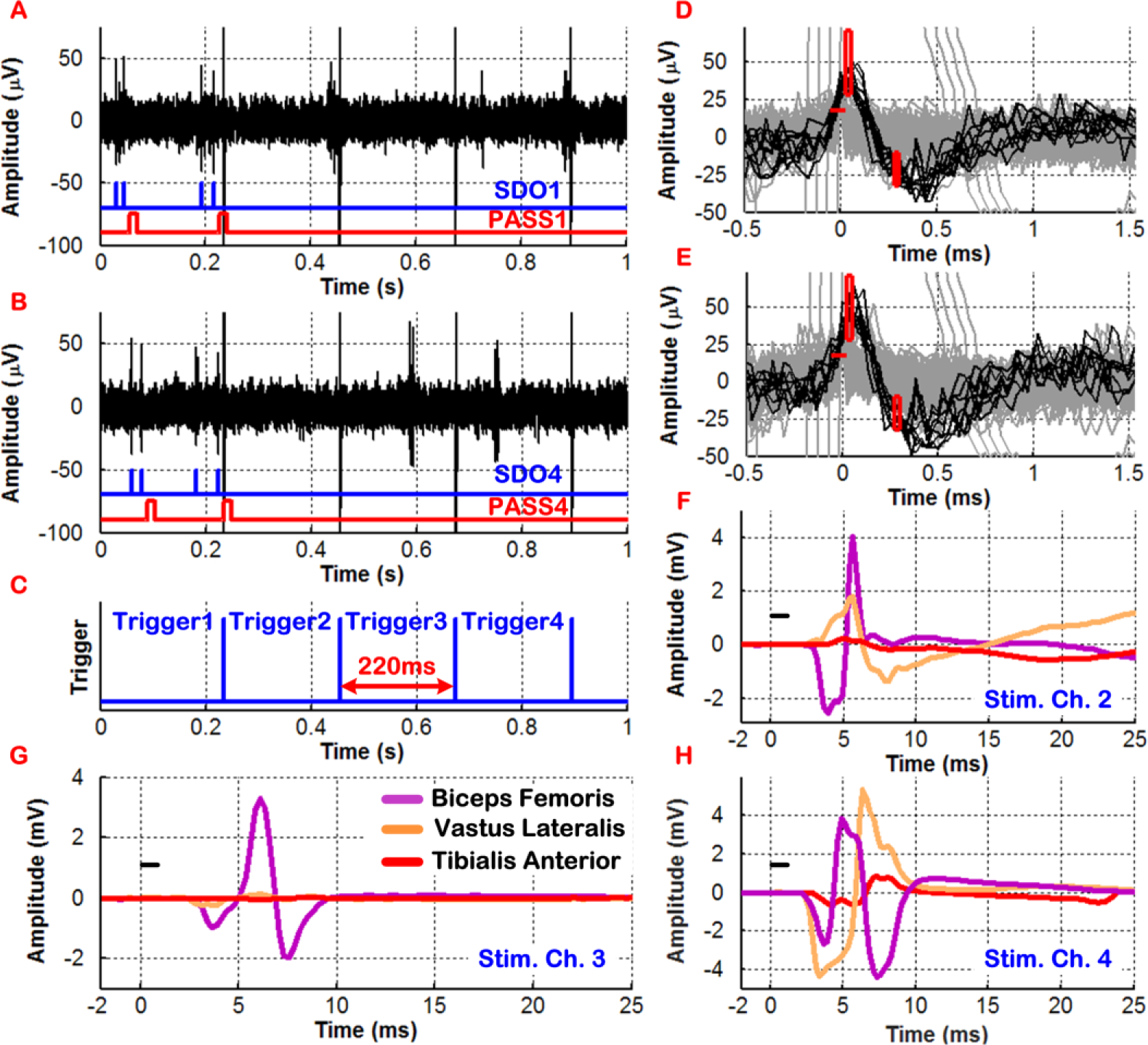
In vivo demonstration of real-time cortical control of ISMS in an SCI rat with sequential triggering based on simultaneous 2-channel discrimination of neural spikes. Plots F–H depict distinct patterns of hindlimb muscle activation by cortically-controlled ISMS.
It should also be noted that once trigger-generation criteria were met, the BSI system employed blanking based on the SEQ_BLK signal to prevent unwanted triggering during the period of sequential ISMS. This was evident in Fig. 10A–B in which the SDO and PASS signals were no longer active once trigger-generation criteria were met shortly after t = 0.2s. Hence, the four stimulus artifacts in Fig. 10A–B, which were time-synchronized with the trigger signals in Fig. 10C, did not result in any false-triggering in the BSI system.
7.4. BSI SoC Core Silicon Area and Power Distribution
Fig. 11 depicts the distribution of the core silicon area and power dissipation of the BSI SoC. The core area of the SoC was 2.78mm × 2.78mm, of which 20% was occupied by the two DSP units. As shown in an accompanying bar chart in Fig. 11, 38.5% of each DSP unit area was occupied by the decision-making circuitry, excluding the blanking control unit that occupied another 1%.
Figure 11:
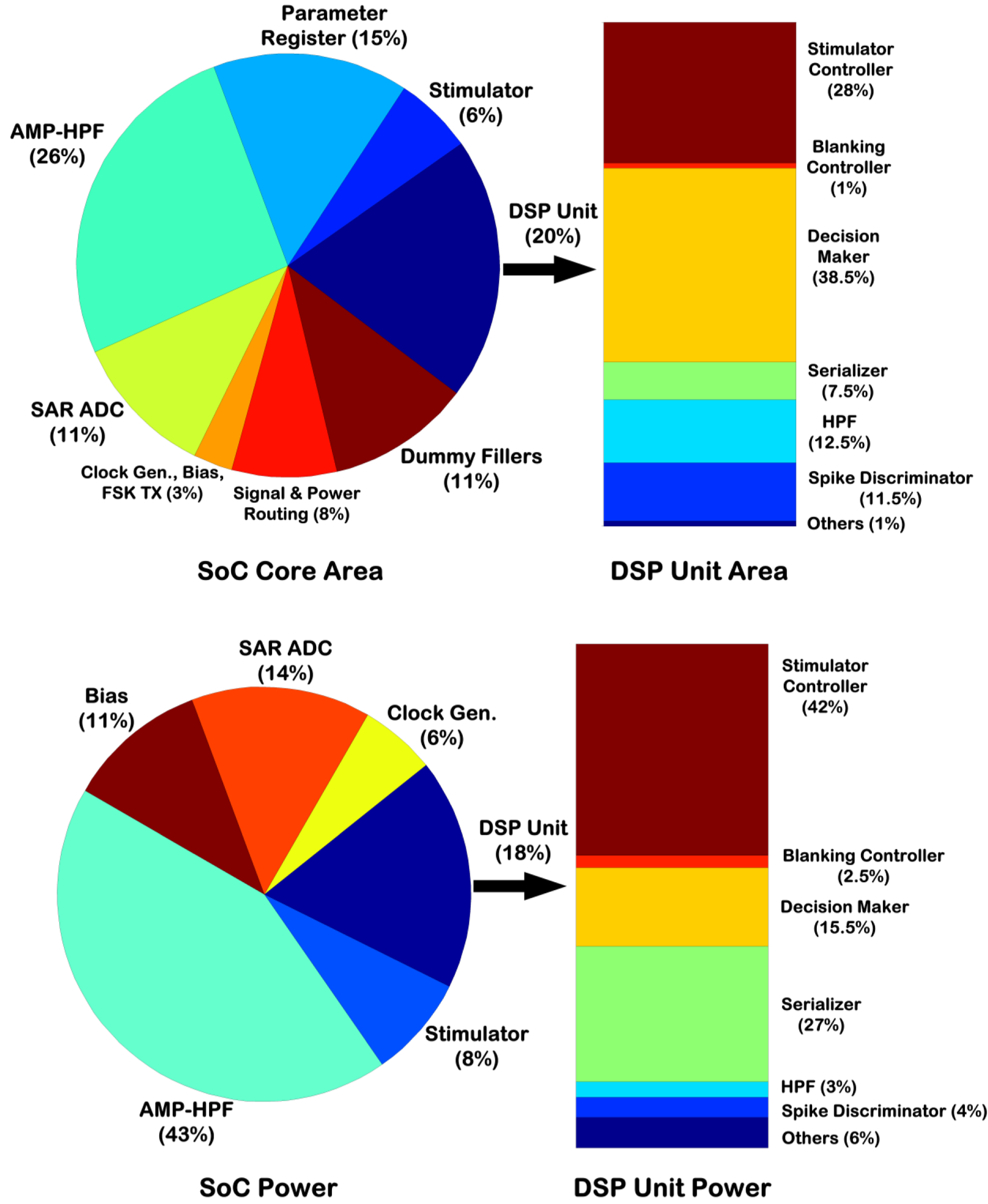
BSI SoC core silicon area and power distribution. The pie charts present the numbers from both modules of the SoC, whereas the bar charts present the numbers from one DSP unit.
The power pie chart was generated assuming a biphasic stimulus at 30Hz (anodic: 100μA, 200μs; cathodic: 33.3μA, 600μs) and recording bandwidth of 525Hz–5.1kHz. Excluding the FSK TX, the power dissipation of the entire SoC was measured to be 359μW, with the recording front-ends dissipating the largest percentage (43%) of SoC power. To obtain the distribution of power dissipation for one DSP unit, it was simulated using the Cadence™ NCSim tool and prerecorded neural data from an in vivo experiment. The resulting switching activity of the DSP unit was subsequently fed to the Encounter Digital Implementation (EDI) tool. The overall power dissipation of each DSP unit was found to be ~ 34.5μW from 1.8V using the typical corner model. This agreed favorably with the measured power dissipation of ~ 32μW from a power supply of 1.5V. The stimulator controller was the most power-hungry block, dissipating 42% of the DSP unit power. Moreover, the leakage power was found to be ~ 71nW.
8. Discussion
The neurobiological experiments in anesthetized rats demonstrated that a variety of predetermined triggering scenarios can be implemented in the BSI system for cortically-controlled ISMS. For example, as demonstrated in the first experiment, short-latency ISMS current pulses could be delivered to activate a single electrode site, resulting in contraction of a selected subset of muscles. Future therapeutic applications may utilize intraspinal stimulating currents that are below the threshold for evoking muscle contraction. This paradigm might be suitable for delivery of spike-timing-dependent stimulus within the physiological limits of Hebbian plasticity to enhance synaptic efficacy. Hence, it is feasible to use the BSI system in conditioning mode, a relatively simple decoding and stimulating paradigm that can potentially operate independent of the user state [22].
The second and third experiments demonstrated that the BSI system can be programmed for ISMS at multiple electrode sites within the spinal cord in a predetermined sequence. This paradigm might be useful in conditioning multiple locations within the spinal cord. It is well known that CS neurons in the motor cortex have multiple branches that often terminate in different spinal cord segments [28]. Hence, it is important for next-generation BSI systems to have independent control over the stimulus timing at each of the spinal cord termination sites.
Finally, as demonstrated in the third experiment, ISMS triggering can be implemented based on the discriminated spikes on multiple recording channels. This ability has one main advantage. By requiring spikes to occur within a narrow time window on multiple channels, it should be possible to reduce triggering events that result from normal spontaneous firing. If spikes generated from neurons within a local network occur closely together in time, it is more likely that they represent functionally relevant, rather than random, events. Furthermore, the ability to discriminate multiple spikes on the same recording channel within a pre-specified time-bin duration will allow re-programming of trigger requirements, if the overall spike rates change over time. Collectively, these tests show the feasibility of designing real-time BSI systems with a variety of input-output relationships for conditioning of descending spinal cord connections.
Any BSI system implementation as proposed herein will require significant advancements in microelectrode design and development of strategies for targeting specific spinal cord regions during implantation [29]. A major limitation of commercial microelectrodes is their inherent stiffness. While microelectrode arrays with stiff shanks have been used successfully in chronic studies in the cerebral cortex, these properties can be more problematic in the spinal cord, leading to breakage and/or tissue damage as the spinal cord moves. Hence, the initial demonstration of the BSI system functionality was performed in acute preparations involving anesthetized rats. Since the anesthetic regimen also alters the firing properties of cortical neurons, the BSI system functionality will ultimately have to be verified in awake animals. Such issues with chronic implantation of intraspinal electrodes in awake ambulatory animals may be mitigated in the near future as electrodes with more elastic properties (e.g., flexible shanks) become available [30].
Moreover, long-term stability of microelectrode recordings of intracortical spike activity still presents technological challenges. This hurdle is critical in a control-mode operation paradigm in which the BSI system and associated microelectrodes will need to be in place for the individual’s lifetime. However, it is possible that a conditioning-mode approach might require a temporary period of synaptic facilitation, especially if it can be implemented within the initial weeks to months after an injury, when the nervous system is particularly plastic. If a temporary treatment can be shown to have long-lasting, or ideally permanent, effects on synaptic efficacy, it is conceivable that a conditioning-mode BSI system will only need to be operational for a short period of time before it is subsequently explanted or its function is turned off. Until future proof-of-concept studies demonstrate that altered synaptic efficacy in descending spinal cord connections can be translated into functional improvement, this potential advantage is largely speculative. But any improvement in volitional movement resulting from enhanced CS efficacy might make the difference in whether an individual can effectively engage in rehabilitative therapy, and thus would have substantial clinical importance.
9. Conclusion
Spinal cord injury (SCI) is a devastating neural injury that currently afflicts > 1 million patients in the Unites States, causing significant financial and emotional burden for the patients and their caregivers. A unique combination of neurobiological tools with next-generation implantable device technology might offer a promising solution to facilitate motor recovery from SCI. This paper reported on the design and development of an integrated brain-spinal interface (BSI) for closed-loop cortically-controlled intraspinal microstimulation (ISMS). The BSI system was validated experimentally in a rat model of SCI by converting in real time multichannel neural spikes recorded from the cerebral cortex into electrical stimuli delivered to the lumbar spinal cord below the level of the injury, resulting in distinct patterns of hindlimb muscle activation in the SCI rat. In the future, this system is envisioned to offer a unique device-based approach for promoting functional recovery from SCI by enhancing the spared corticospinal connections via synaptic facilitation.
Table 1:
Measured Electrical Performance of SoC
| Recording Front-End | Stimulating Back-End | |||
|---|---|---|---|---|
| AC Gain @ 1 kHz | 52.2, 57.5, 60, 65.7 dB | Anodic | Cathodic | |
| Low Cutoff Frequency | 1.1 – 525 Hz | Stimulus Waveform | Asymmetric Biphasic & Monophasic w/Passive Discharge | |
| High Cutoff Frequency | 5.1 – 12.2 kHz | |||
| Total RMS Input Noise Voltage | 3.15 μV (BW = 12.2 kHz) | |||
| Output Current | 0 – 100 μA | 0 – 33.3 μA | ||
| NEF | 2.69 (BW = 12.2 kHz) | |||
| Output Impedance | > 100 MΩ | |||
| Crosstalk | < −69 dB | |||
| CMRR @ 1 kHz | > 55 dB | |||
| PSRR @ 1 kHz | > 63.4 dB | DAC Resolution | 6b | |
| Max. Sampling Frequency | 63 kSa/s | Voltage Compliance | ||
| ADC INL/DNL | < ±0.83 LSB | |||
| ENOB @ 1 kHz | 9.2b (fS = 35.7 kSa/s) 9.1b (fS = 63 kSa/s) |
|||
|
Power Consumption Amp-HPF SAR ADC |
27 μW (BW = 12.2 kHz) 6 μW (@ 1 MHz) |
DAC INL | < ±0.57 LSB | < ±0.47 LSB |
| DAC DNL | < ±0.56 LSB | < ±0.54 LSB | ||
| Supply Sensitivity | −69 nA/V | −10 nA/V | ||
| Power Consumption | 29 μW (Biphasic at 30 Hz, max. currents, anodic phase of 200 μs) | |||
| Digital Signal Processing Unit | ||||
| Filter Cutoff Frequency | 366 Hz & 756 Hz (@ 1 MHz) | ISMS Patterns | Sequential (3 modes), Individual | |
| # of Spikes (N) | ≤ 15 | # of ISMS Pulses per Train | 1 – 31 (5b) | |
| Bin Duration (TBin) | ≤ ~ 0.5 s | ISMS Pulse Freq. per Train | ≥ 122 Hz | |
| Spike-to-Stimulus Delay (TD) | ≤ ~ 28.6 ms | Inter-Channel Delay (TD_Stim) | ≤ ~ 1 s | |
| Power Dissipation | 32 μW (@ 1 MHz) | Blanking Schemes | Sequential, Individual | |
| Clock Generator | RF Transmitter | |||
| Output Frequency | 420 kHz – 2.5 MHz | Communication Scheme | FSK @ ~ 433 MHz | |
| Received Power @ Distance of 1 m | −55 dBm | |||
| Supply Sensitivity | −60 kHz/V | |||
| Power Dissipation | 21 μW (@ 1 MHz) | Power Dissipation | 200 μW | |
Acknowledgment
This work was supported by a generous gift from the Ronald D. Deffenbaugh Family Foundation. The authors would like to thank Dr. Dora Krizsan-Agbas for conducting the spinal cord contusion surgery.
Contributor Information
Shahab Shahdoost, Electrical Engineering and Computer Science Department, Case Western Reserve University, Cleveland, OH 44106 USA..
Jordan Borrell, Bioengineering Graduate Program, University of Kansas, Lawrence, KS 66045 USA..
Pedram Mohseni, Electrical Engineering and Computer Science Department, Case Western Reserve University, Cleveland, OH 44106 USA..
References
- [1].Capogrosso M, et al. (2016). A brain-spine interface alleviating gait deficits after spinal cord injury in primates. Nature, 539, 284–288. [DOI] [PMC free article] [PubMed] [Google Scholar]
- [2].Shahdoost S, et al. (2016). A miniaturized brain-machine-spinal cord interface (BMSI) for closed-loop intraspinal microstimulation. Proc. IEEE Biomed. Circ. Syst. Conf. (BioCAS), pp. 364–367. [Google Scholar]
- [3].Lo YK, et al. (2017). A fully integrated wireless SoC for motor function recovery after spinal cord injury. IEEE Trans. Biomed. Circ. Syst, 11(3), 497–509. [DOI] [PMC free article] [PubMed] [Google Scholar]
- [4].Grahn PJ, et al. (2014). Restoration of motor function following spinal cord injury via optimal control of intraspinal microstimulation: toward a next-generation closed-loop neural prosthesis. Front. Neurosci, 8(296), 1–12. [DOI] [PMC free article] [PubMed] [Google Scholar]
- [5].Zimmermann JB, Jackson A (2014). Closed-loop control of spinal cord stimulation to restore hand function after paralysis. Front. Neurosci, 8(87), 1–8. [DOI] [PMC free article] [PubMed] [Google Scholar]
- [6].Rauschecker JP, Shannon RV (2002). Sending sound to the brain. Science, 295(5557), 1025–1029. [DOI] [PubMed] [Google Scholar]
- [7].Collinger JL, et al. (2013). 7 degree-of-freedom neuroprosthetic control by an individual with tetraplegia. Lancet, 381(9866), 557–564. [DOI] [PMC free article] [PubMed] [Google Scholar]
- [8].Hochberg LR, et al. (2012). Reach and grasp by people with tetraplegia using a neurally controlled robotic arm. Nature, 485, 372–375. [DOI] [PMC free article] [PubMed] [Google Scholar]
- [9].Bouton CE, et al. (2016). Restoring cortical control of functional movement in a human with quadriplegia. Nature, 533, 247–250. [DOI] [PubMed] [Google Scholar]
- [10].Rhew HG, et al. (2014). A fully self-contained logarithmic closed-loop deep brain stimulation SoC with wireless telemetry and wireless power management. IEEE J. Solid-State Circuits, 49(10), 2213–2227. [Google Scholar]
- [11].Abdelhalim K, et al. (2013). 64-channel UWB wireless neural vector analyzer SoC with a closed-loop phase synchrony-triggered neurostimulator. IEEE J. Solid-State Circuits, 48(10), 2494–2510. [Google Scholar]
- [12].Stanslaski S, et al. (2012). Design and validation of a fully implantable, chronic, closed-loop neuromodulation device with concurrent sensing and stimulation. IEEE Trans. Neural Syst. Rehab. Eng, 20(4), 410–421. [DOI] [PubMed] [Google Scholar]
- [13].Zanos S, et al. (2011). The Neurochip-2: An autonomous head-fixed computer for recording and stimulating in freely behaving monkeys. IEEE Trans. Neural Syst. Rehab. Eng, 19(4), 427–435. [DOI] [PMC free article] [PubMed] [Google Scholar]
- [14].Azin M, et al. (2011). A miniaturized system for spike-triggered intracortical microstimulation in an ambulatory rat. IEEE Trans. Biomed. Eng, 58(9), 2589–2597. [DOI] [PubMed] [Google Scholar]
- [15].Azin M, et al. (2011). A battery-powered activity-dependent intracortical microstimulation IC for brain-machine-brain interface. IEEE J. Solid-State Circuits, 46(4), 731–745. [Google Scholar]
- [16].Ethier C, et al. (2012). Restoration of grasp following paralysis through brain-controlled stimulation of muscles. Nature, 485, 368–371. [DOI] [PMC free article] [PubMed] [Google Scholar]
- [17].Moritz CT, Perlmutter SI, Fetz EE (2008). Direct control of paralyzed muscles by cortical neurons. Nature, 456, 639–643. [DOI] [PMC free article] [PubMed] [Google Scholar]
- [18].Nishimura Y, et al. (2013). Spike-timing-dependent plasticity in primate corticospinal connections induced during free behavior. Neuron, 80, 1301–1309. [DOI] [PMC free article] [PubMed] [Google Scholar]
- [19].Nishimura Y, et al. (2013). Restoration of upper limb movement via artificial corticospinal and musculospinal connections in a monkey with spinal cord injury. Front. Neural Circ [DOI] [PMC free article] [PubMed] [Google Scholar]
- [20].Jackson A, Mavoori J, Fetz EE (2006). Long-term motor cortex plasticity induced by an electronic neural implant. Nature, 444, 56–60. [DOI] [PubMed] [Google Scholar]
- [21].McPherson JG, Miller RR, Perlmutter SI (2015). Targeted, activity-dependent spinal stimulation produces long-lasting motor recovery in chronic cervical spinal cord injury. Proc. Natl. Acad. Sci. USA (PNAS), 112(39), 12193–12198. [DOI] [PMC free article] [PubMed] [Google Scholar]
- [22].Guggenmos DJ, et al. (2013). Restoration of function after brain damage using a neural prosthesis. Proc. Natl. Acad. Sci. USA (PNAS), 110(52), 21177–21182. [DOI] [PMC free article] [PubMed] [Google Scholar]
- [23].Shahdoost S, Nudo RJ, Mohseni P (2017). Generation of stimulus triggering from intracortical spike activity for brain-machine-body interfaces (BMBIs). IEEE Trans. Neural Syst. Rehab. Eng, 25(7), 998–1008. [DOI] [PubMed] [Google Scholar]
- [24].Azin M, Mohseni P (2008). A high-output-impedance current microstimulator for anatomical rewiring of cortical circuitry. Proc. IEEE Int. Symp. Circ. Syst. (ISCAS), pp. 2502–2505. [Google Scholar]
- [25].Shahdoost S, et al. (2014). Towards a miniaturized brain-machine-spinal cord interface (BMSI) for restoration of function after spinal cord injury. Proc. 36th Annu. Int. IEEE Eng. Med. Biol. Conf. (EMBC), pp. 486–489. [DOI] [PubMed] [Google Scholar]
- [26].Krizsan-Agbas D, et al. (2014). Gait analysis at multiple speeds reveals differential functional and structural outcomes in response to graded spinal cord injury. J. Neurotrauma, 31, 846–856. [DOI] [PMC free article] [PubMed] [Google Scholar]
- [27].Frost SB, et al. (2015). Output properties of the cortical hindlimb motor area in spinal-cord-injured rats. J. Neurotrauma, 32, 1666–1673. [DOI] [PMC free article] [PubMed] [Google Scholar]
- [28].Shinoda Y, Yamaguchi T, Futami T (1986). Multiple axon collaterals of single corticospinal axons in the cat spinal cord. J. Neurophysiol, 55, 425–448. [DOI] [PubMed] [Google Scholar]
- [29].Grahn PJ, et al. (2016). MRI-guided stereotactic system for delivery of intraspinal microstimulation. Spine, 41(13), 806–813. [DOI] [PMC free article] [PubMed] [Google Scholar]
- [30].Tooker A, et al. (2012). Polymer neural interface with dual-sided electrodes for neural stimulation and recording. Proc. 34th Annu. Int. IEEE Eng. Med. Biol. Conf. (EMBC), pp. 5999–6002. [DOI] [PubMed] [Google Scholar]