Abstract
Host-guest interactions govern the chemistry of a broad range of functional materials, but direct imaging using conventional transmission electron microscopy (TEM) has not been possible. This problem is exacerbated in metal-organic framework (MOF) materials, which are easily damaged by the electron beam. Here, we use cryogenic-electron microscopy (cryo-EM) to stabilize the host-guest structure and resolve the atomic surface of zeolitic imidazolate framework (ZIF-8) and its interaction with guest CO2 molecules. We image step-edge sites on the ZIF-8 surface that provides insight to its growth behavior. Furthermore, we observe two distinct binding sites for CO2 within the ZIF-8 pore, which are predicted by density functional theory (DFT) to be energetically favorable. This CO2 insertion induces an apparent ~3% lattice expansion along the <002> and <011> directions of the ZIF-8 unit cell. The ability to stabilize and preserve host-guest chemistry opens a rich materials space for scientific exploration and discovery using cryo-EM.
Metal-organic frameworks (MOFs) are a large class of highly porous materials1–3 whose chemistry and crystalline structure can be tuned for potential applications in gas storage4–6, separations7, and catalysis8. Interactions between the host framework and guest molecule are central to such applications but are poorly understood at the molecular level. Although transmission electron microscopy (TEM) has been used to study the empty MOF framework9–14, imaging sub-nanometer guest insertion within the MOFs is still challenging. Of note, a recent study successfully imaged guest single-molecule magnets via TEM, but at relatively low dosage and large molecular size (> 1 nm)14. The weak bonding between the guest molecule and framework is easily damaged even under low electron doses15,16. Furthermore, guest molecules are likely to desorb from MOF pores under the high vacuum condition (~10−6 mbar) of the TEM at room temperature (supplementary text). Therefore, current studies rely on ensemble measurements using X-ray/neutron diffraction17,18, nuclear magnetic resonance19, or theoretical simulations20. However, the structural information obtained by these methods is averaged over bulk particles. Direct observations of individual MOF particles and their interaction with subnanometer guest species at high spatial resolution have not been possible.
Recently, cryogenic-electron microscopy (cryo-EM) was shown to be a powerful tool beyond structural biology. For instance, reactive lithium battery materials have been successfully stabilized for imaging and spectroscopy21–25. Such cryogenic condition may also reduce radiation damage to the MOF framework (supplementary text). However, cryo-EM procedures developed for biological or battery materials are not necessarily compatible with MOFs. Here, we establish a new cryo-EM protocol to reveal atomic host-guest structures within MOFs, demonstrating that these entities, held together by weak interactions, can be preserved for high-resolution imaging at cryogenic condition (Fig. 1). As an example of this general approach, we investigate the surface structure of a zeolitic imidazolate framework (ZIF-8) and its host-guest chemistry with CO2 molecules, with potential implications for both carbon capture and gas separations26.
Figure 1 |. Preserving and stabilizing host-guest interactions using Cryo-EM.
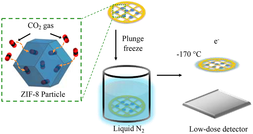
Vacuum-dried ZIF-8 particles are exposed to CO2 gas at ambient temperature and pressure after synthesis. In this environment, the particles are then plunge-frozen directly into liquid nitrogen to freeze in the host-guest structure and chemistry. Low-dose images are then recorded at cryogenic condition using a direct electron detector.
ZIF-8 is a body-centered cubic crystal that has a sodalite topology (space group ). The ZIF-8 particles (~100 nm in diameter) synthesized in this study (fig. S2) are confirmed to be highly crystalline via X-ray diffraction (XRD; fig. S1). Diffraction contrast from the ZIF-8 particles observed in low-magnification TEM images (Fig. 2a) further suggests a crystalline specimen. However, the bonding between the inorganic metal centers (Zn2+) and the organic linkers (2-methylimidazole) of the ZIF-8 framework is extremely sensitive to high electron doses. After exposure to ~50 e−/Å2 at room temperature, the ZIF-8 particle quickly becomes amorphized, as indicated by both the high-resolution TEM (HRTEM) image (Fig. 2b) and its fast Fourier transform (FFT; Fig. 2b inset). Indeed, previous studies12,13 have shown that MOF materials quickly lose their crystallinity with an accumulated electron dose of only ~10-20 e−/Å2, with ZIF-8 becoming completely amorphous after 70 e−/Å2 at room temperature. Consequently, any existing host-guest structure would be difficult to identify from the amorphized particle. To overcome these challenges, we established a flash-freezing protocol modified from cryo-EM methodologies used in structural biology27 to preserve the MOFs at their operating environment (e.g. empty or filled) for high-resolution imaging. First, the as-synthesized ZIF-8 particles were dispersed onto a carbon support TEM grid and vacuum-dried to remove all solvent from the ZIF-8 pore space. Samples were then directly plunged into liquid nitrogen while maintaining vacuum or kept in a 1 bar pressure CO2 environment (Fig. 1a, methods). This freezing process prevents any air exposure and kinetically inhibits CO2 desorption from the ZIF-8, preserving the host-guest interactions that were present at room temperature.
Figure 2 |. Electron irradiation of ZIF-8 at cryogenic temperatures.
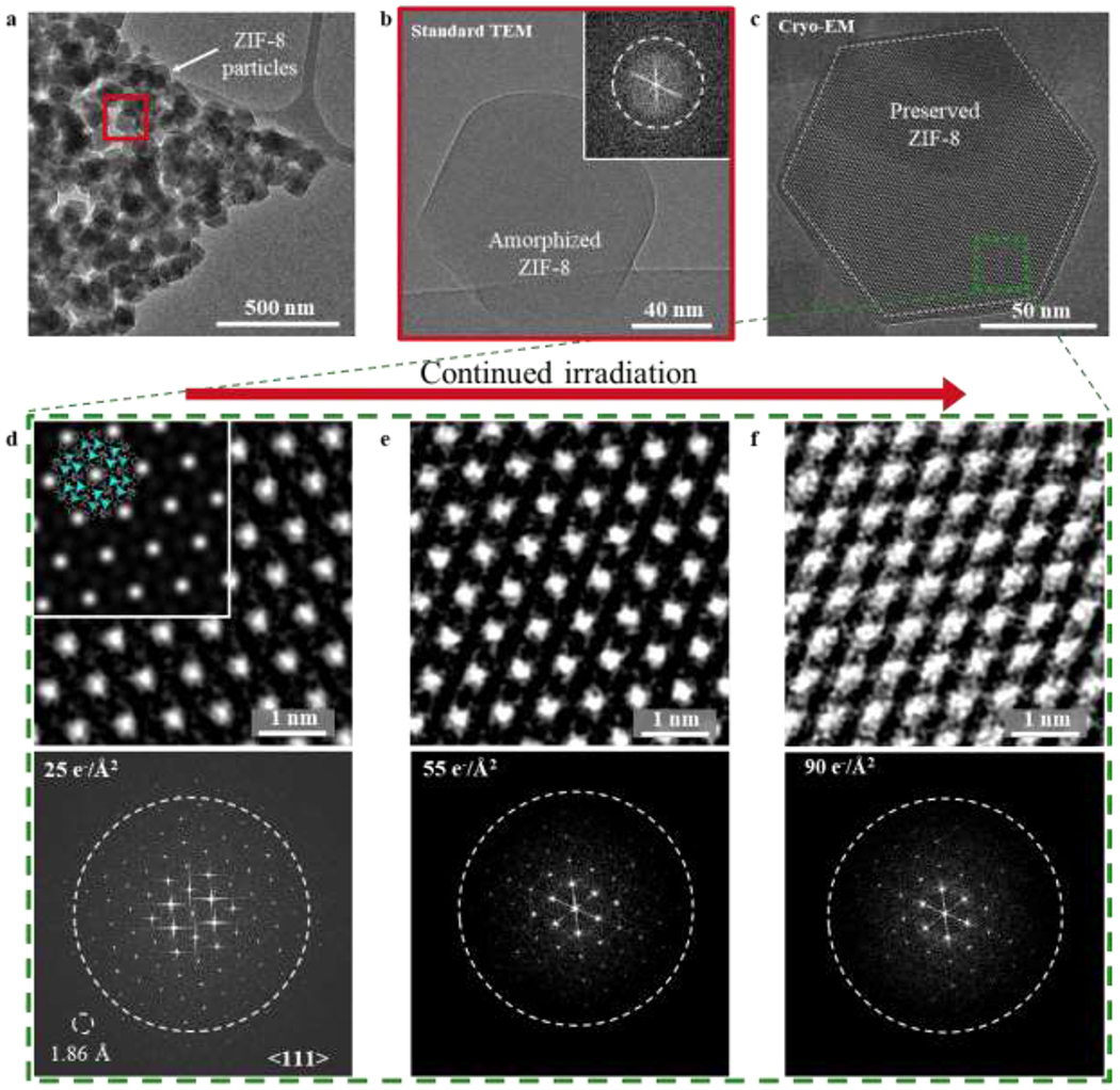
a, TEM image of ZIF-8 particles taken at room temperature with electron dose rate 2 e−/Å2/s for ~1s. Diffraction contrast suggests sample is crystalline. b, HRTEM image of red boxed region from (a). After accumulated electron dose of ~50 e−/Å2, ZIF-8 becomes completely amorphous. Inset: corresponding FFT showing no crystallinity in the sample. c, Cryo-EM image of ZIF-8 (outlined by dashed white line) taken along the <111> direction at −170 °C with electron dose rate of ~4.5 e−/Å2/s for 1.5s. At 225 nm underfocus, bright spots in the ZIF-8 lattice correspond to empty pore space. d, e, f, Magnified images of green boxed region from (c) exposed to electron doses of 25 e−/Å2 (d), 50 e−/Å2 (e), and 90 e−/Å2 (f) with corresponding FFT pattern below. The dashed circle on the FFT represents an information transfer of 2.5 Å. Information transfer of 1.86 Å is possible, as indicated by the reflection circled in (d). Inset of (d): The ZIF-8 atomic structure is overlaid onto the simulated TEM image, which is calculated using 225 nm underfocus and 100 nm sample thickness. The simulated image matches reasonably well with the experimental cryo-EM image.
Cryogenic temperature is known to reduce radiation damage induced by the electron beam15,28. In our cryo-EM imaging experiment, we keep the specimen at −170 °C and expose it to different cumulative electron doses to determine its radiation damage sensitivity (fig. S7). We use a magnification corresponding to a pixel size of 0.68 Å by 0.68 Å to facilitate imaging at atomic resolution. In addition, a direct-detection electron-counting camera has a high quantum efficiency to enable acquisition of images with high signal-to-noise at all frequencies and a high frame rate to allow recording of multiple frames per specimen area followed by subsequent frame alignment to minimize beam-induced drift29.
Figure 2c is a typical cryo-EM image of a ZIF-8 particle that was held under vacuum before flash-freezing. When viewed along the <111> zone axis, the ZIF-8 rhombic dodecahedral particle is hexagonal (dashed white lines) with well-defined {011} edge planes joined by sharp vertices (fig. S3). Furthermore, the crystalline structure of the ZIF-8 particle is clearly preserved. Under low dose and low temperature conditions, the ZIF-8 structure shows structure information down to 1.86 Å as evidenced by the FFT of this image (Fig. 2d, bottom), exceeding previously reported resolutions of ZIF-8. A simulated TEM image (Fig. 2d inset) also shows good agreement with the raw image. Even after exposure to 25 e−/Å2 that would ordinarily result in significant damage to the framework, ZIF-8 remains pristine at low temperatures (Fig. 2d). When the number of frames taken and the cumulative exposure are increased (Fig. 2e, f), ZIF-8 shows only partial loss of crystallinity after 90 e−/Å2 at low temperature, while the same specimen becomes fully amorphous after exposure of 50 e−/Å2 at room temperature (Fig. 2b). Quantitatively, the plot of normalized intensity in the FFT as a function of cumulative electron exposure (fig. S7) demonstrates that high-resolution information (3 Å) is still retained after 90 e−/Å2. These experiments and the corresponding raw, unprocessed images (fig. S5) establish the increased stability of ZIF-8 using cryo-EM, allowing further exploration into its surface atomic structure and host-guest chemistry.
The atomic surfaces of materials often provide insight into their growth mechanism. In particular, the shape and size uniformity of ZIF-8 particles has been attributed to the formation of surface steps30,31. Unfortunately, surface structures and their possible defects are more sensitive than the bulk to the electron beam, making atomic-resolution imaging difficult even at low electron doses12. To preserve and study such surface structures immediately after growth, the as-synthesized ZIF-8 particles were flash-frozen and imaged without vacuum-drying (methods). Using ~7 e−/Å2 cumulative electron dose, we have made a number of structure feature observations which were previously not seen at room temperature. Figure 3a is a denoised32 cryo-EM image of ZIF-8 after synthesis, which appears to be free of defects in the bulk and directly matches the ZIF-8 crystal structure projected along the <111> direction. Briefly, denoising was done by subtracting amorphous background signal from the Fourier transform to improve the visibility of crystalline components. At an overfocus of 250 nm, the hexagonal columns of bright contrast correspond to the “Zn clusters” centers of the framework, as confirmed by TEM simulation (methods). Here, we denote a “Zn cluster” as the collection of Zn metal centers and connecting ligands that comprise one of the six ZIF-8 hexagonal vertices visible along the <111> projection (Figure 3b inset). With cryo-EM, it is now possible to resolve atomically sharp surfaces of ZIF-8, demonstrating the striking resolution and stability afforded by this technique. We find that the exposed {011} ZIF-8 surfaces terminate with doubly-coordinated Zn clusters, indicating that Zn clusters on the surface are joined with two other clusters. By reducing the number of dangling ligands, this doubly-coordinated Zn cluster conformation exposes a thermodynamically stable termination surface. Interestingly, these surfaces are not atomically pristine. Instead, step-edge defects are clearly present in regions I (Fig. 3b) and II (Fig. 3c), which may play an important role in the growth mechanism of ZIF-8. Particle growth of ZIF-8 requires the addition of Zn clusters to the exposed surface. This process is not random. Whereas any two adatom clusters of Zn at a surface site would only be single-coordinated, addition of any two Zn clusters at a step-edge site would enable double-coordination of both (Fig. 3d). Therefore, it is thermodynamically favorable for ZIF-8 growth to initiate at step-edge sites rather than surface sites (Fig. 3e), which is consistent with our observations (fig. S4, S6). Finally, bright intensity is visible inside the 6-ring channels of ZIF-8 (Fig. 3b, c), which may come from the solvent molecule within the pore that exists during synthesis (i.e. acetone or methanol). Along with this observation, the low vapor pressure of guest molecules at cryogenic temperature (~10−10 mbar for CO2) suggests that host-guest interactions can be stabilized for imaging using cryo-EM (supplementary text).
Figure 3 |. Atomic surface and step-edge sites of ZIF-8 particles.
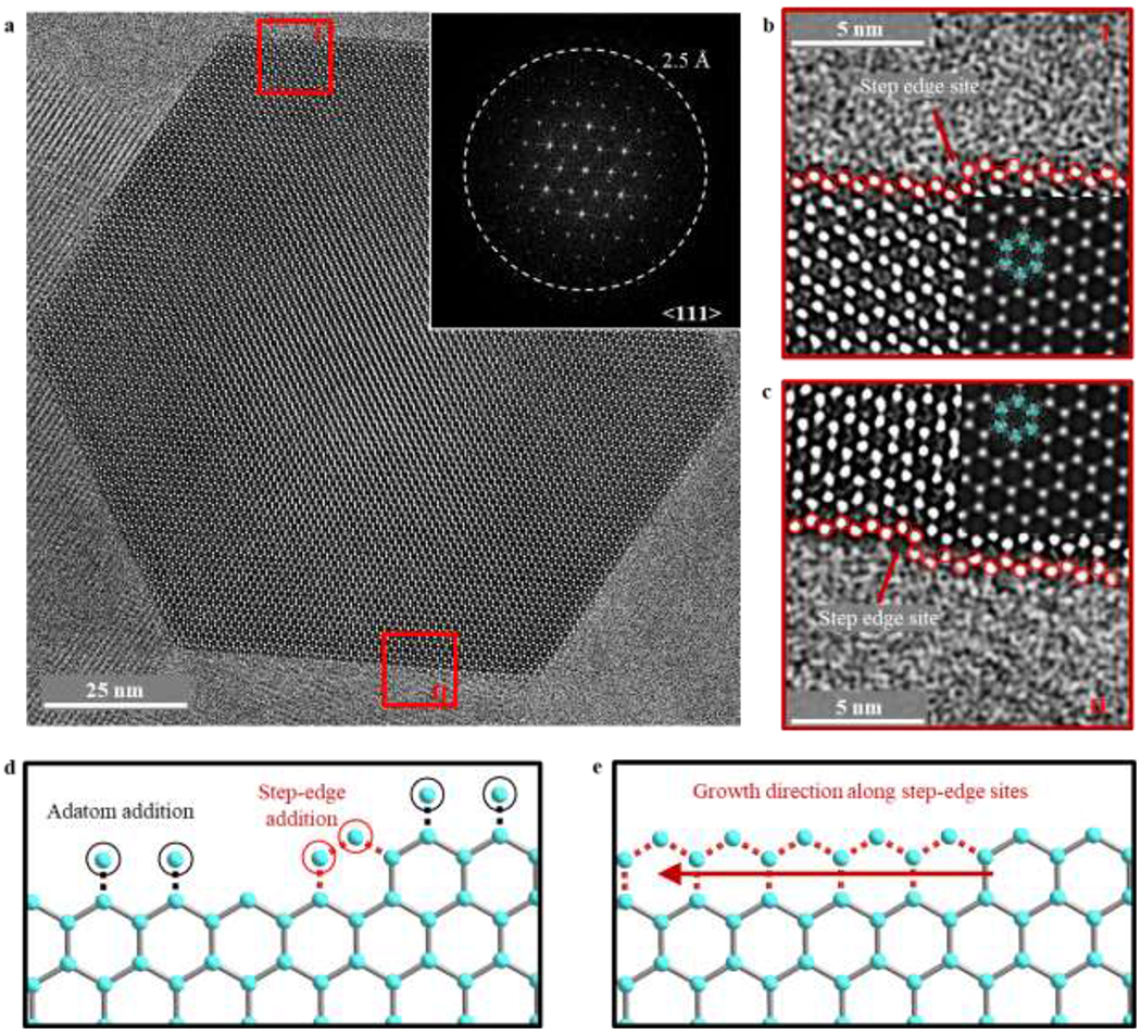
a, Denoised cryo-EM image of ZIF-8 after synthesis (not vacuum-dried) taken at 250 nm overfocus with electron dose rate of ~4.5 e−/Å2/s for 1.5s. Bright spots correspond to Zn clusters. Inset: corresponding FFT pattern. White dashed circle represents information transfer of 2.5 Å. b, c, Magnified images of region I (b) and region II (c) boxed in red from (a). The ZIF-8 atomic structure is overlaid onto a simulated TEM image in the second inset, which is calculated using 250 nm overfocus and 100 nm sample thickness. The simulated TEM image matches well with the experimental cryo-EM image. The Zn clusters on the surface are double-coordinated and are outlined in red circles. A step-edge site is observed in both (b) and (c), indicated by the red arrow. d, Schematic of possible surface additions of Zn clusters during ZIF-8 growth. Whereas adatom addition (circled in black) would result in single-coordinated Zn clusters, addition at the step-edge site (circled in red) would result in double-coordinated Zn clusters. e, Schematic of ZIF-8 growth initiated at the step-edge site, which is thermodynamically more favorable.
Raw, unprocessed cryo-EM images of an empty (Fig. 4a) and CO2-filled (Fig. 4d) ZIF-8 particle appear to be very similar when taken at an underfocus of 225 nm. To make a fair comparison between these two images, we correct the “contrast inversion” (methods) introduced by the contrast transfer function (CTF) of the objective lens33. Here, the weak-phase object approximation applies to sample thicknesses up to ~100 nm owing to the low density of ZIF-8, which reduces its effective scattering thickness13. This standard image processing procedure (methods) generates CTF-corrected images of empty ZIF-8 (Fig. 4b) and CO2-filled ZIF-8 (Fig. 4e) in which the regions of bright intensity represent mass density34,35, making interpretation of such CTF-corrected images more straightforward. Zn clusters at the unit cell vertices appear as bright dots, forming the expected hexagonal honeycomb lattice along the <111> projection in both the empty and filled ZIF-8 particle. Within the ZIF-8 pore, distinguishing features between the empty and filled state are quite dramatic. Whereas density is absent within the center pore space of empty ZIF-8 unit cells, bright contrast is clearly visible in the middle of the CO2-filled ZIF-8 pore. This suggests that CO2 adsorption is centered within the 6-ring window along the <111> direction. Indeed, TEM simulations (fig. S8, S9) and density-functional theory (DFT) calculations of favorable CO2 binding sites in ZIF-8 support our observations36. Using such calculations, we simulate the structure of a ZIF-8 unit cell with the DFT-optimized binding location of CO2 molecules (simplified as red spheres) projected along the <111>. The simulated structure (Fig. 4g) matches well with the CTF-corrected cryo-EM image (Fig. 4e), providing strong evidence that CO2 molecules are successfully preserved within the framework at cryogenic conditions and can be directly imaged using cryo-EM.
Figure 4 |. Host-guest structures within ZIF-8 viewed along <111> projection.
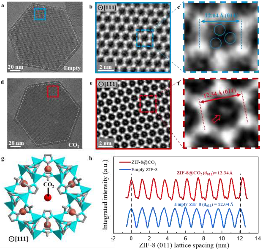
a, Cryo-EM image of vacuum-dried, empty ZIF-8 (outlined by white dashed lines) taken with electron dose rate of ~4.5 e−/Å2/s for 1.5s along the <111> projection. b, CTF-corrected denoised image of blue boxed region from (a). Bright regions correspond to mass density. c, Magnified image of a single ZIF-8 unit cell from (b). Density (circled in blue) near the interior edge of the unit cell may correspond to the organic imidazolate linkers. d, Cryo-EM image of CO2-filled ZIF-8 particle (outlined by white dashed lines) taken with electron dose rate of ~4.5 e−/Å2/s for 1.5s along the <111> projection. e, CTF-corrected denoised image of red boxed region from (d). Bright regions correspond to mass density. Contrast in the center of the 6-ring window is clearly observed for multiple unit cells. f, Magnified image of a single ZIF-8 unit cell from (e). Density at the center of the unit cell (indicated by red arrow) likely corresponds to CO2 adsorbed within ZIF-8. g, Simulated structure of ZIF-8 with DFT-predicted binding site of CO2 (simplified as red spheres) along the <111> projection. This is consistent with the experimental cryo-EM image from (f). h, Integrated intensity of ZIF-8 plotted over 10 unit cells along the <011> direction, indicating a 3% lattice expansion when CO2 is introduced to ZIF-8.
Close inspection of a single ZIF-8 unit cell reveals several key features of the host material during guest insertion. In the empty ZIF-8 pore (Fig. 4c), there are three areas of density (circled in blue) just inside the edges of the unit cell. This contrast likely comes from the three organic imidazolate linkers that protrude into the pore space, forming the 6-ring windows that connect each individual pore. Interestingly, these moieties are not observed in ZIF-8 unit cells after CO2 loading (Fig. 4f), suggesting that the imidazolate linkers can rotate out of view to open the narrow 6-ring window (3.4 Å) for CO2 (3.3 Å kinetic diameter) adsorption and diffusion throughout the framework. These results support previous descriptions of a “gate opening” phenomenon in ZIF-8, which explain how molecules larger than the 6-ring window (e.g. N2 3.6 Å kinetic diameter) can be accommodated into ZIF-8 pores via linker rotation37–40. Although it is generally accepted that flexibility of the 6-ring windows occurs at various loading conditions, the ZIF-8 pore cavity itself is largely thought to remain rigid upon CO2 insertion at ambient pressures. Surprisingly, we discover a 3% expansion of the <011> lattice repeat during CO2 loading at atmospheric pressure. Figure 4h plots the integrated pixel intensities for the empty and CO2-filled ZIF-8 unit cells along the <011> direction. The <011> lattice spacing for the empty ZIF-8 averaged over 10 unit cells is measured to be 12.04 Å (fig. S10), which matches well with the experimental value of 12.03 Å from XRD measurement37. The precision in this TEM lattice measurement is approximately 0.07 Å (methods). After CO2 loading, the ZIF-8 <011> lattice expands to 12.34 Å (fig. S11). Though lattice expansions of this magnitude (~3%) are possible for ZIF-8 (ref. 41), they have predominantly been observed at high pressure loadings (~104 bar) of non-interacting gas molecules (e.g. N2, O2, Ar). However, the CO2 still induces a similar unit cell expansion at much lower pressure (~1 bar CO2 loading) in our experiments. This observation implies a strong interaction between CO2 and the ZIF-8 framework, which further suggests ZIF-8 might be a promising carbon capture material.
To reinforce our results, it is important to investigate the host-guest structures along more than one zone axis. Projected in the <001> direction, the rhombic dodecahedral ZIF-8 particle appears as a square (Fig. 5a, 5d). With CTF-correction to address the contrast inversion issue mentioned above, the cryo-EM images of empty (Fig. 5b) and CO2-filled (Fig. 5e) ZIF-8 can be more easily interpreted. Contrast is strongest for the Zn clusters, which are located at the bright square spots. These clusters are connected by the imidazolate linkers that are visible as lines of white contrast. When viewed along the <001> direction (Fig. 5c), ZIF-8 displays two structurally distinct pore cavities: one is located at the vertex of the Zn cluster (circled in green) and the second is adjacent to the square edge of the Zn cluster (boxed in orange). Both cavities do not appear to contain any density in the empty ZIF-8 (Fig. 5c). Upon CO2 adsorption, bright contrast can be observed in the center of the 4-ring window (Fig. 5f). Interestingly, this appears only in the pore cavity located at the vertex of the Zn cluster and not the cavity at the Zn cluster edge. Although adsorption at the center of these particular 4-ring windows is different from the CO2 binding location observed along the <111> direction, DFT calculations show that CO2 binding centered around the 4-ring window is also energetically favorable36. The simulated ZIF-8 structure with the predicted CO2 adsorption site (Fig. 5g) closely resembles the cryo-EM image (Fig. 5f), indicating that more than one adsorption site exists. Furthermore, the lattice expansion observed for the <011> direction is also present along the <002> direction (Fig. 5h). Whereas an 8.56 Å <002> lattice spacing is measured for the empty ZIF-8 (fig. S12), the <002> expands 3% to 8.78 Å after CO2 insertion (fig. S13). The similar unit cell expansion and additional adsorption sites revealed here demonstrate the increased information gained by simply observing the particles along different crystallographic directions. To identify possible adsorption sites beyond the two observed here, a full tomographic tilt series of a single ZIF-8 particle can now be enabled by the additional stability afforded by cryo-EM.
Figure 5 |. Host-guest structures within ZIF-8 viewed along <001> projection.
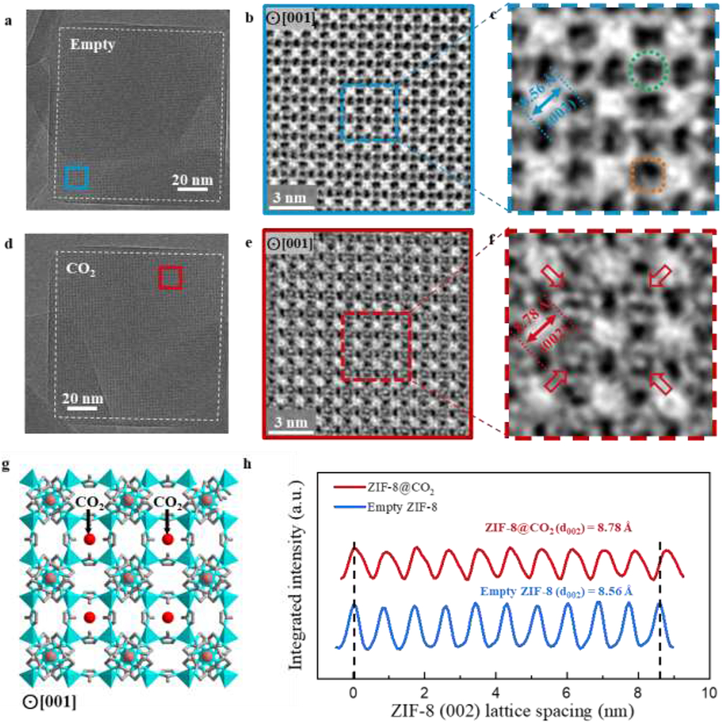
a, Cryo-EM image of vacuum-dried, empty ZIF-8 (outlined by white dashed lines) taken with electron dose rate of ~4.5 e−/Å2/s for 1.5s along the <001> projection. b, CTF-corrected denoised image of blue boxed region from (a). Bright regions correspond to mass density. c, Magnified image of ZIF-8 unit cells in blue box from (b). Green circle indicates pore cavity at the vertices of the Zn clusters. Orange square indicates pore cavity at the edges of the Zn clusters. d, Cryo-EM image of CO2-filled ZIF-8 particle (outlined by white dashed lines) taken with electron dose rate of ~4.5 e−/Å2/s for 1.5s along the <001> projection. e, CTF-corrected denoised image of red boxed region from (d). Bright regions correspond to mass density. Contrast near the center of the 4-ring window is clearly observed for multiple unit cells. f, Magnified image of ZIF-8 unit cells in red box from (e). Density near the center of the unit cell (indicated by red arrows) likely corresponds to CO2 adsorbed within ZIF-8. Note that only the pore cavity at the vertices of the 4-ring window contain the density in the center. g, Simulated structure of ZIF-8 with DFT-predicted binding site of CO2 (simplified as red spheres) along the <001> projection. This is consistent with the experimental cryo-EM image from (f). h, Integrated intensity of ZIF-8 plotted over 10 unit cells along the <002> direction, indicating a 3% lattice expansion when CO2 is introduced to ZIF-8
Our work here demonstrates the powerful utility for cryo-EM to preserve and image atomic MOF surface structures and guest molecules within its pore cavities. We revealed that ZIF-8 growth likely initiates at a step-edge surface site and discovered structural changes in ZIF-8 during CO2 insertion. This study opens opportunities to further investigate such host-guest interactions to develop a complete picture of MOF adsorption kinetics at the single particle level. Using cryo-EM, the many applications of different MOFs with distinct guest molecules can be probed at the atomic level. New discoveries and findings will provide insight to their fundamental operation and shape future designs of these tunable materials.
Supplementary Material
Acknowledgements
The authors thank Dave Bushnell and Dong-Hua Chen for training at the Stanford-SLAC cryo-EM facilities. Yuzhang Li acknowledges the Intelligence Community Fellowship for funding. Part of this work was performed at the Stanford Nano Shared Facilities (SNSF), supported by the National Science Foundation under award ECCS-1542152. R.S. acknowledges support from the National Institutes of Health (NIH) under grant no. U54 CA199075. W.C. acknowledges support by the NIH under grant nos. P41GM103832 and S10OD021600. Y.C. acknowledges support from the Department of Energy, Office of Basic Energy Sciences, Division of Materials Science and Engineering, under contract DE-AC02-76SF00515.
Footnotes
Supplementary information is available in the online version of the paper.
Competing financial interests
The authors declare no competing financial interests.
References and Notes
- 1.Li H, Eddaoudi M, O’Keeffe M & Yaghi OM Design and synthesis of an exceptionally stable and highly porous metal-organic framework. Nature 402, 276 (1999). [Google Scholar]
- 2.Yaghi OM et al. Reticular synthesis and the design of new materials. Nature 423, 705 (2003). [DOI] [PubMed] [Google Scholar]
- 3.Furukawa H, Cordova KE, O’Keeffe M & Yaghi OM The chemistry and applications of metal-organic frameworks. Science 341, 1230444 (2013). [DOI] [PubMed] [Google Scholar]
- 4.Eddaoudi M et al. Systematic design of pore size and functionality in isoreticular MOFs and their application in methane storage. Science 295, 469–472 (2002). [DOI] [PubMed] [Google Scholar]
- 5.Rosi NL et al. Hydrogen storage in microporous metal-organic frameworks. Science 300, 1127–1129 (2003). [DOI] [PubMed] [Google Scholar]
- 6.Sumida K et al. Carbon dioxide capture in metal–organic frameworks. Chem. Rev 112, 724–781 (2011). [DOI] [PubMed] [Google Scholar]
- 7.Li J-R, Kuppler RJ & Zhou H-C Selective gas adsorption and separation in metal–organic frameworks. Chem. Soc. Rev 38, 1477–1504 (2009). [DOI] [PubMed] [Google Scholar]
- 8.Lee J et al. Metal–organic framework materials as catalysts. Chem. Soc. Rev 38, 1450–1459 (2009). [DOI] [PubMed] [Google Scholar]
- 9.Lebedev OI, Millange F, Serre C, Van Tendeloo G & Férey G First direct imaging of giant pores of the metal− organic framework MIL-101. Chem. Mater 17, 6525–6527 (2005). [Google Scholar]
- 10.Cravillon J et al. Rapid room-temperature synthesis and characterization of nanocrystals of a prototypical zeolitic imidazolate framework. Chem. Mater 21, 1410–1412 (2009). [Google Scholar]
- 11.Wiktor C, Turner S, Zacher D, Fischer RA & Van Tendeloo G Imaging of intact MOF-5 nanocrystals by advanced TEM at liquid nitrogen temperature. Microporous Mesoporous Mater. 162, 131–135 (2012). [Google Scholar]
- 12.Zhu Y et al. Unravelling surface and interfacial structures of a metal–organic framework by transmission electron microscopy. Nat. Mater 16, 532 (2017). [DOI] [PubMed] [Google Scholar]
- 13.Zhang D et al. Atomic-resolution transmission electron microscopy of electron beam–sensitive crystalline materials. Science 359, 675–679 (2018). [DOI] [PubMed] [Google Scholar]
- 14.Aulakh D et al. Direct Imaging of Isolated Single-Molecule Magnets in Metal–Organic Frameworks. J. Am. Chem. Soc 141, 2997–3005 (2019). [DOI] [PubMed] [Google Scholar]
- 15.Egerton RF, Li P & Malac M Radiation damage in the TEM and SEM. Micron 35, 399–409 (2004). [DOI] [PubMed] [Google Scholar]
- 16.Wiktor C, Meledina M, Turner S, Lebedev OI & Fischer RA Transmission electron microscopy on metal–organic frameworks–a review. J. Mater. Chem. A 5, 14969–14989 (2017). [Google Scholar]
- 17.Rowsell JLC, Spencer EC, Eckert J, Howard JAK & Yaghi OM Gas adsorption sites in a large-pore metal-organic framework. Science 309, 1350–1354 (2005). [DOI] [PubMed] [Google Scholar]
- 18.Easun TL, Moreau F, Yan Y, Yang S & Schröder M Structural and dynamic studies of substrate binding in porous metal–organic frameworks. Chem. Soc. Rev 46, 239–274 (2017). [DOI] [PubMed] [Google Scholar]
- 19.Witherspoon VJ, Xu J & Reimer JA Solid-State NMR Investigations of Carbon Dioxide Gas in Metal–Organic Frameworks: Insights into Molecular Motion and Adsorptive Behavior. Chem. Rev (2018). [DOI] [PubMed] [Google Scholar]
- 20.Landers J, Gor GY & Neimark AV Density functional theory methods for characterization of porous materials. Colloids Surfaces A Physicochem. Eng. Asp 437, 3–32 (2013). [Google Scholar]
- 21.Li Y et al. Atomic structure of sensitive battery materials and interfaces revealed by cryo–electron microscopy. Science 358, 506–510 (2017). [DOI] [PubMed] [Google Scholar]
- 22.Wang X et al. New insights on the structure of electrochemically deposited lithium metal and its solid electrolyte interphases via cryogenic TEM. Nano Lett. 17, 7606–7612 (2017). [DOI] [PubMed] [Google Scholar]
- 23.Zachman MJ, Tu Z, Choudhury S, Archer LA & Kourkoutis LF Cryo-STEM mapping of solid–liquid interfaces and dendrites in lithium-metal batteries. Nature 560, 345 (2018). [DOI] [PubMed] [Google Scholar]
- 24.Li Y et al. Correlating structure and function of battery interphases at atomic resolution using cryoelectron microscopy. Joule 2, 2167–2177 (2018). [Google Scholar]
- 25.Li Y, Li Y & Cui Y Catalyst: How Cryo-EM Shapes the Development of Next-Generation Batteries. Chem 4, 2250–2252 (2018). [Google Scholar]
- 26.Park KS et al. Exceptional chemical and thermal stability of zeolitic imidazolate frameworks. Proc. Natl. Acad. Sci 103, 10186–10191 (2006). [DOI] [PMC free article] [PubMed] [Google Scholar]
- 27.Chiu W Electron microscopy of frozen, hydrated biological specimens. Annu. Rev. Biophys. Biophys. Chem 15, 237–257 (1986). [DOI] [PubMed] [Google Scholar]
- 28.Egerton RF Mechanisms of radiation damage in beam‐sensitive specimens, for TEM accelerating voltages between 10 and 300 kV. Microsc. Res. Tech 75, 1550–1556 (2012). [DOI] [PubMed] [Google Scholar]
- 29.Li X et al. Electron counting and beam-induced motion correction enable near-atomic-resolution single-particle cryo-EM. Nat. Methods 10, 584 (2013). [DOI] [PMC free article] [PubMed] [Google Scholar]
- 30.Moh PY, Cubillas P, Anderson MW & Attfield MP Revelation of the molecular assembly of the nanoporous metal organic framework ZIF-8. J. Am. Chem. Soc 133, 13304–13307 (2011). [DOI] [PubMed] [Google Scholar]
- 31.Wagia R, Strashnov I, Anderson MW & Attfield MP Insight and control of the crystal growth of zeolitic imidazolate framework ZIF-67 by atomic force microscopy and mass spectrometry. Cryst. Growth Des 18, 695–700 (2018). [Google Scholar]
- 32.Kilaas R Optimal and near‐optimal filters in high‐resolution electron microscopy. J. Microsc 190, 45–51 (1998). [Google Scholar]
- 33.Zou X, Hovmöller S & Oleynikov P Electron crystallography: electron microscopy and electron diffraction. 16 (Oxford University Press, 2011). [Google Scholar]
- 34.Rohou A & Grigorieff N CTFFIND4: Fast and accurate defocus estimation from electron micrographs. J. Struct. Biol 192, 216–221 (2015). [DOI] [PMC free article] [PubMed] [Google Scholar]
- 35.Zhang K Gctf: Real-time CTF determination and correction. J. Struct. Biol 193, 1–12 (2016). [DOI] [PMC free article] [PubMed] [Google Scholar]
- 36.Fischer M & Bell RG Interaction of hydrogen and carbon dioxide with sod-type zeolitic imidazolate frameworks: a periodic DFT-D study. CrystEngComm 16, 1934–1949 (2014). [Google Scholar]
- 37.Fairen-Jimenez D et al. Opening the gate: framework flexibility in ZIF-8 explored by experiments and simulations. J. Am. Chem. Soc 133, 8900–8902 (2011). [DOI] [PubMed] [Google Scholar]
- 38.Zhang C et al. Unexpected molecular sieving properties of zeolitic imidazolate framework-8. J. Phys. Chem. Lett 3, 2130–2134 (2012). [DOI] [PubMed] [Google Scholar]
- 39.Haldoupis E, Watanabe T, Nair S & Sholl DS Quantifying Large Effects of Framework Flexibility on Diffusion in MOFs: CH4 and CO2 in ZIF‐8. ChemPhysChem 13, 3449–3452 (2012). [DOI] [PubMed] [Google Scholar]
- 40.Zhang K et al. Exploring the framework hydrophobicity and flexibility of ZIF-8: from biofuel recovery to hydrocarbon separations. J. Phys. Chem. Lett 4, 3618–3622 (2013). [Google Scholar]
- 41.Hobday CL et al. Understanding the adsorption process in ZIF-8 using high pressure crystallography and computational modelling. Nat. Commun 9, 1429 (2018). [DOI] [PMC free article] [PubMed] [Google Scholar]
Associated Data
This section collects any data citations, data availability statements, or supplementary materials included in this article.


