Abstract
Background
Over the past half-century, cardiac pacing technology has been reported. In this study, we designed, prepared, and tested the performance of a self-energized cardiac pacemaker driven by piezoelectric vibration energy collection technology, which converts the kinetic energy of the heart into electrical energy. A record in vivo output current of 54 nA was obtained in an adult rat by the implanted piezoelectric transducer.
Methods
First, the kinetic energy of the heart was collected by an implanted piezoelectric energy collector and supplied to the cardiac pacemaker. Then, the heart was pierced from the outside, and the cardiac tissue was stimulated by the pacing electrode, and self-powered pacing.
Results
The average voltage and average current of the piezoelectric vibration energy harvester in vitro were 3.5 mV and 60 nA, respectively. After implantation of the device into rats, the average voltage and current were measured immediately and reached 3.2 mV and 54 nA, respectively. The average voltage and average current reached 3.0 mV and 48 nA after 1 week, and 2.1 mV and 31 nA after 12 weeks. The electrical performance of the self-powered pacemaker in this study is based on piezoelectric energy collection technology. The implanted piezoelectric vibration energy collector drives the pacemaker to generate electrical pulses, which directly stimulates the myocardial tissue through the epicardium to achieve the pacing effect.
Conclusions
These results evidence the feasibility of the in-situ epicardial pacing strategy. This research will promote the design and development of self-powered cardiac pacemakers.
Keywords: Self-powered, piezoelectric vibration energy harvesters, electrical properties, cardiac pacemaker
Introduction
Pacemakers are among the most common electronic medical devices implanted to aid in the restoration of heart function in clinical practice. Using a pulse generator to provide battery-powered electrical pulses, pacemakers excite and contract the heart by stimulating the heart muscle through electrodes. They are applied in the treatment of some cardiac dysfunctions caused by arrhythmias and heart failure (1-3). At present, implanted medical devices such as pacemakers are used to maintain normal vital signs in millions of patients worldwide (4). With the wide application of pacemakers, many complications related to batteries and implanted devices of pacemakers can also arise (5,6). Furthermore, routine battery replacement to ensure adequate power supply is inavoidable, but this greatly increases the health risks for patients. Therefore, the development of self-powered pacemakers has become the main priority of pacemaker-related research.
Researchers have exerted great efforts to develop novel self-powered medical devices. The optimal approach is direct conversion of biomechanical energy (such as muscle stretching, heartbeat, blood flow, and gas flow caused by respiration) into electrical energy (7-9). Mechanisms of biomechanical energy conversion include electromagnetic induction, triboelectricity, staticity, and piezoelectricity (7,10,11). Among them, the piezoelectric method has the greatest application prospect in implantable self-powered medical devices, as it holds potential for high power density, high output stability, and device flexibility (12,13). However, challenges still exist in creating commercial pacemakers that can be directly driven by implantable piezoelectric energy collectors (14). Attaining adequate power output to drive pacemakers has become a key challenge for implantable piezoelectric energy collectors (15). The efficiency of piezoelectric energy collectors is closely related to the piezoelectric material, manufacturing process, structural design, implantation position, and mode of energy collection (16,17).
Therefore, we designed a new type of pacemaker model with self-energized characteristics. By using an implantable piezoelectric energy collector, the kinetic energy of the heart was collected and supplied to the pacemaker chip to attain an effective pacing treatment, and self-functional pacing was achieved by stimulating the cardiac tissue with a pacing electrode. Piezoelectric energy harvesting is the key to this new self-powered cardiac pacemaker, and is also the main focus of verification in this paper.
We present the following article in accordance with the ARRIVE reporting checklist (available at http://dx.doi.org/10.21037/atm-21-2073).
Methods
Design of the self-powered cardiac pacemaker system based on piezoelectric vibration energy acquisition technology
Figure 1 shows the structural design parameters and the material selection for the piezoelectric energy collector. The cystic piezoelectric element was prepared by bending components in a fixed position at an angle of 5 degrees to the left and right sides. Figure 2 compares and analyzes the stress distribution and output voltage characteristics of the piezoelectric layer of the device under the same displacement function without (Figure 2A) and with (Figure 2B) a metal layer. As shown in the figure, we found that the metal layer allowed stress to be distributed more evenly on the piezoelectric layer, and could generate a higher voltage output. As the 2 piezoelectric layers have identical properties and a function frequency of 1 Hz, we inferred that they would have matching resistors. Therefore, the energy collector with the higher voltage output characteristics would generate a higher power output. This indicated that the piezoelectric energy collector with a flexible metal layer would have better energy conversion efficiency.
Figure 1.
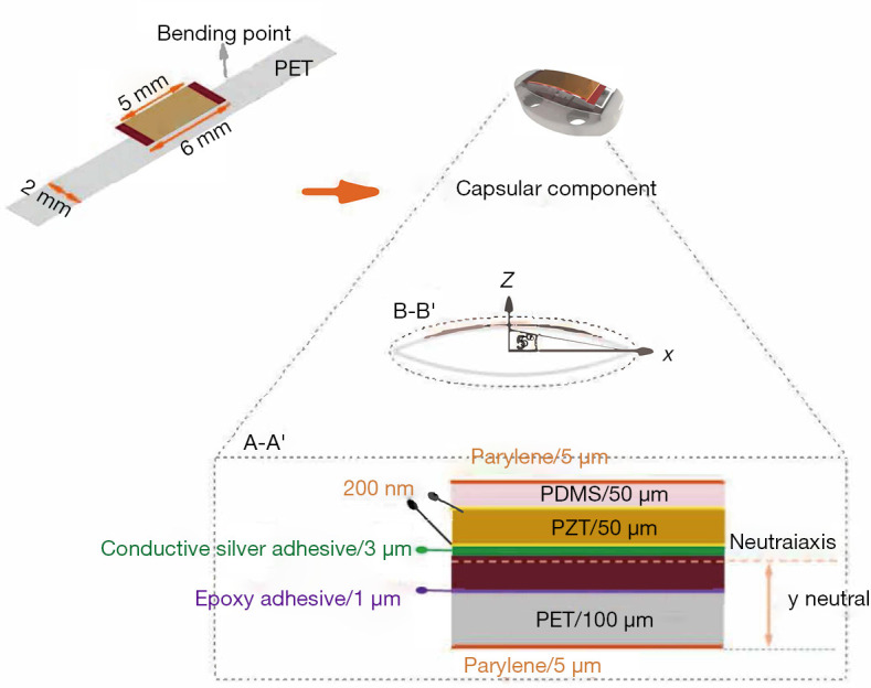
Design and dimensional annotation of the flexible piezoelectric energy harvester.
Figure 2.
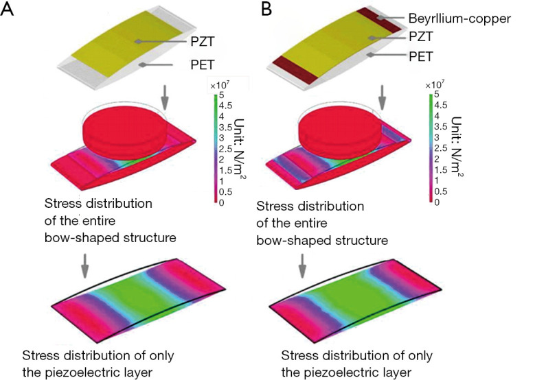
Finite element analysis of the piezoelectric energy harvester unit with and without a metal layer. (A) Results of finite element analysis for stress distribution and the corresponding output voltage of the piezoelectric energy harvester unit without a beryllium-copper layer. (B) Results of finite element analysis for stress distribution and the corresponding output voltage of the piezoelectric energy harvester unit with a beryllium-copper layer under the same vertex deformation of 1.54 mm.
Preparation of piezoelectric vibration energy harvester
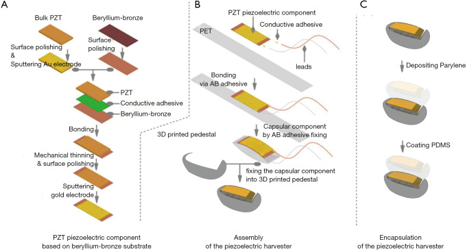
Figure 3 shows the detailed construction process of the piezoelectric vibration energy collector. The flexible buckling piezoelectric laminated layer comprises 3 layers: the piezoelectric layer, metal, and polymer. Firstly, the PMM-Pt [(72%) Pb (MGI/3NB2/3)O3 − (28%) PbTiO3, 300 µm, TrSx2A, TrS Ceramics] was graphed into rectangular blocks of 10×20×0.3 mm3 using ultraviolet (UV) laser cutting at 800 W (Figure 3A). It was then bonded to the polished bronze substrate (10×25×0.05 mm3) with epoxy conductive silver adhesive at 100 °C, and then subjected to 24 hours of vacuum hot-pressing. Next, a mechanical grinding method was employed to reduce the PMN-PT sheet to a thickness of 50 µm. Under the condition of air pressure 1.5 Pa and power 100 W, Cr/Au (−200 nm) film, as the top electrode, was deposited by magnetic sputtering (TRP-450, Sky Technology Development Co., Ltd., Shenyang, China). Polarization of the PMN-Pt piezoelectric film was performed by applying a 3.5 kV/cm electric field at 20 °C for 10 minutes with a high voltage electrode (C2911Bi Nanjing Owen Instrument Technology Co., Ltd., Nanjing, China). The beryllium copper foil was bonded to the central position of the 10×60×0.1 mm3 polyethylene terephthalate (PET) film with an epoxy resin binder (Figure 3B). Leads were used to connect the gold electrode at the top with the Copper electrode at the bottom through a silver epoxy conductive adhesive. Finally, the flexural structure was bent and fixed using PET with a string length of 30 mm.
Figure 3.
Fabrication process of the piezoelectric energy harvester. (A) Fabrication process of the piezoelectric component. The (B) assembly and (C) encapsulation of the piezoelectric energy harvester.
To prevent the device from slipping after implantation, the piezoelectric composite layer element was fixed with an auxiliary base, the concave of which was designed to match the convex surface of the heart and was made using three-dimensional (3D) printing technology and polylactic acid (PLA) material with high biocompatibility. Figure 3C shows the core/shell packaging process used to isolate the device from body fluids and tissues, for which leakproof biocompatible materials including polydimethylsiloxane (PDMS) and polyparaxylene C were used. PDMS (Sylgard184, Downing Corning, USA) was coated on the surface of the piezoelectric energy collector and distributed as uniformly as possible (≈40 µm) by airflow. Then, the inner gas was removed into a vacuum chamber, and finally cured at 80 °C for 1 hour to form the PDMS encapsulation layer. As PDMS is vulnerable to damage, to further improve the reliability and leakproof performance of the PDMS layer, a polyparylene C (parylene C) film with a thickness of 5 µm was laid on the outer surface as a second packaging layer to ensure the device was electrically insulated and packaged reliably.
Statistical analysis
SPSS 24.0 software was used for statistical analysis. The experimental data were expressed as mean ± standard deviation (). The independent sample t-test and one-way analysis of variance (ANOVA) were applied, and the homogeneity of variance test was performed at the same time. When the variance was homogeneous, the LSD statistical method was used for comparisons between groups. P<0.05 indicated a significant difference.
In vitro test of the output performance of the piezoelectric vibration energy harvester
The open-circuit voltage and short-circuit current were under the peak loading forces of 0.5 and 0.6 N at the frequencies of 1, 2, and 3 Hz.
In vitro test results of the piezoelectric vibration energy harvester
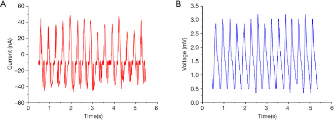
The open-circuit output characteristics of the piezoelectric energy collector are shown in Figure 4. Using the piezoelectric energy harvester, the open-circuit voltage and the short-circuit current increased to 3.5 mv and 60 nA, respectively.
Figure 4.
Analysis of the in vitro output performance of the piezoelectric energy harvester. The electrical properties of the piezoelectric energy harvester were measured with the thumb pressed against the side of the index finger: (A) current (nA): 60, and (B) voltage (mV): 3.5.
In vivo experiment of the piezoelectric energy collector
All animal experiments were approved by the Naval Military Medical University (Second Military Medical University) Animal Care Center (CHEC2019-103), following all guidelines, regulations, legal, and ethical standards as required. The in vivo experiment was performed in female Sprague Dawley (SD) rats (age: 6–7 weeks, weight: 170–180 g). Three rats were in one cage. There are 6 cages. Before surgery, the rats were fasted for 12 hours. Anesthesia was maintained with Rodent Anesthesia Machine and isoflurane at a flow rate of 0.7 L/min. After being anesthetized, the rats were fixed on the operating table, with the head of the table maintained at 60 degrees. The rats’ chest hair was removed with depilation cream, and cold light was applied to the chest. The rats were disinfected 3 times with iodine volt and covered with surgical towel.
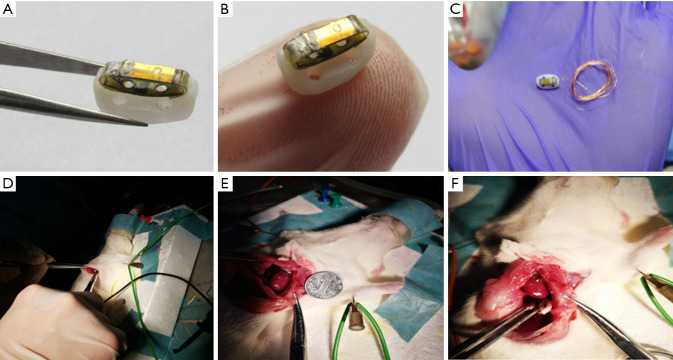
The subcutaneous fascia, pectoralis major, and serratus anterior were separated by a longitudinal incision 2–3 mm from the left edge of the sternum, to expose the 3rd and 4th ribs. The intercostal muscles of the 3rd and 4th ribs were obtusely separated, and then these ribs were gently spread. The pleura was cut with ophthalmic scissors, with the left lung being carefully protected. Then, the pericardium was cut, and the chest was opened with eyelid openers to fully expose the bottom of the heart. A preprepared UV-sterilized flexible flexion piezoelectric vibratory energy collector was then quickly implanted and fixed in the pericardium, facing the apex of the heart. The blood around the chest was cleaned with a cotton swab and observed for bleeding spots. After it had been confirmed that there was no bleeding, the skin was sutured with thread 0 and disinfected with iodine volt. Finally, the anesthetic machine was removed, and the rats were placed in a cage. The surgical method is shown in Figure 5.
Figure 5.
The process of implanting the piezoelectric vibrator near the cardiac apex. (A) The piezoelectric vibrator for rats; (B) the piezoelectric vibrator prototype compared with an index finger; (C) the piezoelectric vibrator with wire; (D) chest incisions; (E) size comparison between exposed rat hearts and a coin; (F) after implantation of the piezoelectric vibrator.
Results
In vivo test results of the piezoelectric vibration energy harvester
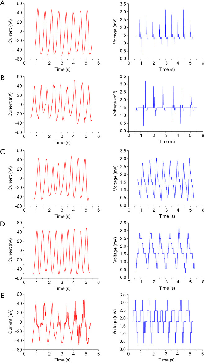
Figure 6 shows the time series data of the output current plotted for different voltage sweep frequencies after implantation of the piezoelectric vibrator.
Figure 6.
Time series data of the output current plotted for different voltage sweep frequencies after implantation of the piezoelectric vibrator.
Table 1 shows the results of the piezoelectric vibration energy collector in vitro. The average test voltage and average current of the device were approximately 3.5 mV and 60 nA, respectively. After implantation of the device into rats, the average immediate test voltage reached 3.2 mV and the average current was 54 nA. At 1 week after implantation, the average test voltage and the average current were approximately 3.0 mV and 48 nA, respectively. At 12 weeks after implantation, the average test voltage and the average current were approximately 2.1 mV and 31 nA, respectively. Both the voltage and current showed a gradual downward trend in vivo.
Table 1. Summary of output current plotted for different voltages after implantation of the piezoelectric vibrator.
| Parameter/implant time | In vitro | Immediately after implantation | After 1 week | After 2 weeks | After 4 weeks | After 12 weeks |
|---|---|---|---|---|---|---|
| Voltage (mV) | 3.5 | 3.2 | 3.0 | 2.8 | 2.6 | 2.1 |
| Current (nA) | 60 | 54 | 48 | 43 | 39 | 31 |
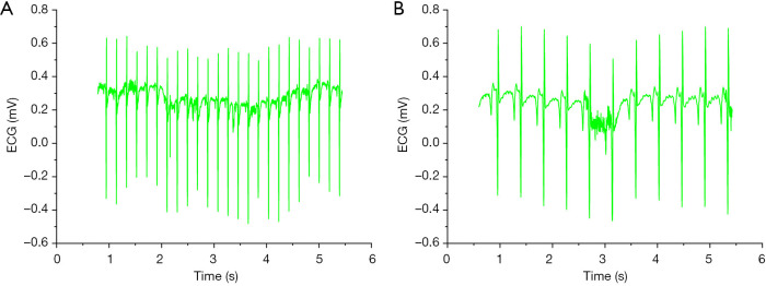
We also measured the heart rate of the rats before and after implantation of the piezoelectric vibrational energy collector. As shown in Figure 7A, the heart rate of the rats was 190 beats/min before implantation, and as shown in Figure 7B, the rate was 188 beats/min after device implantation.Then, the rats were euthanized according to the rules.
Figure 7.
Heart rate of the rats before and after implantation of the piezoelectric vibrator. (A) Heart rate of the rats before device implantation: 190 beats/min; (B) heart rate of the after device implantation: 188 beats/min.
Discussion
Figure 8 shows a schematic illustration of the circuits of the piezoelectric vibrator. Following this strategy, here we present a first step in this direction.. At the same time, a strategy of epicardial in situ pacing was proposed, and a method for constructing a self-powered cardiac pacemaker was explored.
Figure 8.
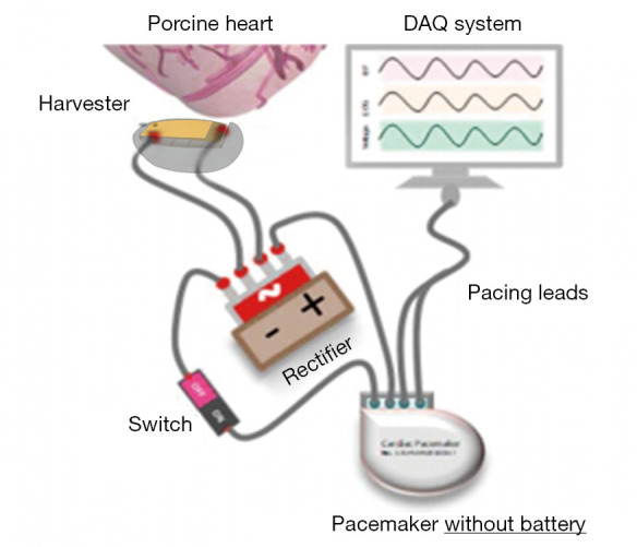
Schematic illustration of the circuits of the piezoelectric vibrator.
Based on the heart state and the internal environment of rats, a piezoelectric vibration energy collector was designed to collect the kinetic energy of the heart. The preparation and packaging processes, and the implantation procedure were carried out, and the mechanical and electrical reliability of the device was evaluated.
Before the device was implanted into the rats, the average voltage was 3.5 mV and and the average current was 60 nA; after implantation, the average voltage was 3.2 mV and the average current was 54 nA. One week after the implantation procedure, the average test voltage and the average current were 3.0 mV and 48 nA, respectively; after 2 weeks, the average test voltage and the average current were 2.8 mV and 43 nA, respectively; after 4 weeks, the average voltage and average current were 2.6 mV and 39 nA, respectively; and after 12 weeks, the average test voltage and the average current were 2.1 mV and 31 nA, respectively.
After connecting the output electricity to batteries removed from commercial heart pacemakers, we obtained the required electrical pulse signals and verified that the heart kinetic energy collected by the implanted piezoelectric vibratory energy collector was sufficient to maintain the normal level of work of a commercial pacemaker, thus showing the feasibility of using implantation-based piezoelectric energy harvesting technology in the operation of self-powered cardiac pacemakers.
Herein, we have presented an epicardial pacing strategy in which a pacemaker is driven by an implanted piezoelectric vibratory energy collector, which generates electrical pulses, and the cardiac tissue is directly stimulated through the epicardial membrane to achieve a pacing effect. Our results prove the feasibility of using this in-situ epicardial pacing strategy. This research will contribute to the promotion of the design and development of cardiac pacemakers.
Supplementary
The article’s supplementary files as
Acknowledgments
Funding: This work was supported by the National Natural Science Foundation of China (grant no. 81470592).
Ethical Statement: The authors are accountable for all aspects of the work in ensuring that questions related to the accuracy or integrity of any part of the work are appropriately investigated and resolved. The research experiments conducted in this article involving animals were approved by the Ethical Committee and responsible authorities of Naval Military Medical University (No. CHEC2019-103) following all guidelines, regulations, legal, and ethical standards as required.
Reporting Checklist: The authors have completed the ARRIVE reporting checklist. Available at http://dx.doi.org/10.21037/atm-21-2073
Data Sharing Statement: Available at http://dx.doi.org/10.21037/atm-21-2073
Conflicts of Interest: All authors have completed the ICMJE uniform disclosure form (available at http://dx.doi.org/10.21037/atm-21-2073). The authors have no conflicts of interest to declare.
(English Language Editor: J. Reynolds)
References
- 1.Göbel CH, Göbel A, Niederberger U, et al. Occipital Nerve Stimulation in Chronic Migraine: The Relationship Between Perceived Sensory Quality, Perceived Sensory Location, and Clinical Efficacy-A Prospective, Observational, Non-Interventional Study. Pain Ther 2020;9:615-26. 10.1007/s40122-020-00194-0 [DOI] [PMC free article] [PubMed] [Google Scholar]
- 2.Tsai SY, Maass K, Lu J, et al. Efficient Generation of Cardiac Purkinje Cells from ESCs by Activating cAMP Signaling. Stem Cell Reports 2015;4:1089-102. 10.1016/j.stemcr.2015.04.015 [DOI] [PMC free article] [PubMed] [Google Scholar]
- 3.Bhattacharyya S, Bhakta M, Munshi NV. Phenotypically silent Cre recombination within the postnatal ventricular conduction system. PLoS One 2017;12:e0174517. 10.1371/journal.pone.0174517 [DOI] [PMC free article] [PubMed] [Google Scholar]
- 4.Catalan-Matamoros D, Lopez-Villegas A, Tore-Lappegard K, et al. Patients' experiences of remote communication after pacemaker implant: The NORDLAND study. PLoS One 2019;14:e0218521. 10.1371/journal.pone.0218521 [DOI] [PMC free article] [PubMed] [Google Scholar]
- 5.Zhang T, Liu Y, Zou C, et al. Single chamber permanent epicardial pacing for children with congenital heart disease after surgical repair. J Cardiothorac Surg 2016;11:61. 10.1186/s13019-016-0439-6 [DOI] [PMC free article] [PubMed] [Google Scholar]
- 6.Swanson LE, Huibregtse BA, Scansen BA. A retrospective review of 146 active and passive fixation bradycardia lead implantations in 74 dogs undergoing pacemaker implantation in a research setting of short term duration. BMC Vet Res 2018;14:112. 10.1186/s12917-018-1431-2 [DOI] [PMC free article] [PubMed] [Google Scholar]
- 7.Elvira-Hernández EA, Romero-García J, Ledezma-Pérez A, et al. Synthesis of ZnO Nanorod Film Deposited by Spraying with Application for Flexible Piezoelectric Energy Harvesting Microdevices. Sensors (Basel) 2020;20:6759. 10.3390/s20236759 [DOI] [PMC free article] [PubMed] [Google Scholar]
- 8.Chung J, Heo D, Kim B, et al. Superhydrophobic Water-Solid Contact Triboelectric Generator by Simple Spray-On Fabrication Method. Micromachines (Basel) 2018;9:593. 10.3390/mi9110593 [DOI] [PMC free article] [PubMed] [Google Scholar]
- 9.Quattrocchi A, Montanini R, De Caro S, et al. A New Approach for Impedance Tracking of Piezoelectric Vibration Energy Harvesters Based on a Zeta Converter. Sensors (Basel) 2020;20:5862. 10.3390/s20205862 [DOI] [PMC free article] [PubMed] [Google Scholar]
- 10.Xu Z, Shan X, Yang H, et al. Parametric Analysis and Experimental Verification of a Hybrid Vibration Energy Harvester Combining Piezoelectric and Electromagnetic Mechanisms. Micromachines 2017;8:189. 10.3390/mi8060189 [DOI] [Google Scholar]
- 11.Park IW, Kim KW, Hong Y, et al. Recent Developments and Prospects of M13- Bacteriophage Based Piezoelectric Energy Harvesting Devices. Nanomaterials (Basel) 2020;10:93. 10.3390/nano10010093 [DOI] [PMC free article] [PubMed] [Google Scholar]
- 12.Kim HS, Lee DW, Kim DH, et al. Dominant Role of Young's Modulus for Electric Power Generation in PVDF−BaTiO3 Composite-Based Piezoelectric Nanogenerator. Nanomaterials (Basel) 2018;8:777. 10.3390/nano8100777 [DOI] [PMC free article] [PubMed] [Google Scholar]
- 13.You S, Zhang L, Gui J, et al. A Flexible Piezoelectric Nanogenerator Based on Aligned P(VDF-TrFE) Nanofibers. Micromachines (Basel) 2019;10:302. 10.3390/mi10050302 [DOI] [PMC free article] [PubMed] [Google Scholar]
- 14.Gruenwald W, Bhattacharrya M, Jansen D, et al. Electromagnetic Analysis, Characterization and Discussion of Inductive Transmission Parameters for Titanium Based Housing Materials in Active Medical Implantable Devices. Materials (Basel) 2018;11:2089. 10.3390/ma11112089 [DOI] [PMC free article] [PubMed] [Google Scholar]
- 15.Chae SH, Ju S, Choi Y, et al. Electromagnetic Linear Vibration Energy Harvester Using Sliding Permanent Magnet Array and Ferrofluid as a Lubricant. Micromachines (Basel) 2017;8:288. 10.3390/mi8100288 [DOI] [PMC free article] [PubMed] [Google Scholar]
- 16.Pan CT, Wang SY, Yen CK, et al. Polyvinylidene Fluoride-Added Ceramic Powder Composite Near-Field Electrospinned Piezoelectric Fiber-Based Low-Frequency Dynamic Sensors. ACS Omega 2020;5:17090-101. 10.1021/acsomega.0c00805 [DOI] [PMC free article] [PubMed] [Google Scholar]
- 17.Ostasevicius V, Janusas G, Milasauskaite I, et al. Peculiarities of the third natural frequency vibrations of a cantilever for the improvement of energy harvesting. Sensors (Basel) 2015;15:12594-612. 10.3390/s150612594 [DOI] [PMC free article] [PubMed] [Google Scholar]
Associated Data
This section collects any data citations, data availability statements, or supplementary materials included in this article.
Supplementary Materials
The article’s supplementary files as


