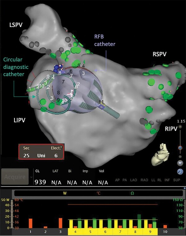
Figure 1.

The RFB and circular diagnostic catheter as visualised using the electroanatomical mapping system. The RFB and the circular diagnostic catheter are shown at the ostium of LIPV during ablation, where the bottom panel reflects the RF power being delivered (yellow bar, 0–40 W), temperature measured (orange bar, 0–60 Celsius), starting impedance (dark green, 0–150 Ohms), and current impedance (bright green, 0–150 Ohms) for each of the 10 individual electrodes. The bottom panel also shows the posterior electrodes #1–#3 are turned off. LIPV, left inferior pulmonary vein; LSPV, left superior pulmonary vein; RF, radiofrequency; RFB, radiofrequency balloon catheter; RIPV, right inferior pulmonary vein; RSPV, right superior pulmonary vein.
