Abstract
Purpose
This study aims to characterize the performance of a prototype rapid kilovoltage (kV) x‐ray image guidance system onboard the newly released Halcyon 2.0 linear accelerator (Varian Medical Systems, Palo Alto, CA) by use of conventional and innovatively designed testing procedures.
Methods
Basic imaging system performance tests and radiation dose measurements were performed for all eleven kV‐cone beam computed tomography (CBCT) imaging protocols available on a preclinical Halcyon 2.0 LINAC. Both conventional CBCT reconstruction using the Feldkamp–Davis–Kress (FDK) algorithm and a novel, advanced iterative reconstruction (iCBCT) available on this platform were evaluated. Standard image quality metrics, including slice thickness accuracy, high‐contrast resolution, low‐contrast resolution, regional uniformity and noise, and CT Hounsfield unit (HU) number accuracy and linearity were evaluated using a manufacturer‐supplied QUART phantom (GmbH, Zorneding, Germany) and an independent image quality phantom (Catphan 500, The Phantom Laboratory, New York, NY). Due to the simplified design of the QUART phantom, we developed surrogate and clinically feasible strategies for measuring slice thickness and high‐ and low‐contrast resolution. Imaging dose delivered by these eleven protocols was measured using a computed tomography dose index phantom and pencil chamber with commonly accepted methods and procedures. A subset of measurements were repeated on a conventional C‐arm LINAC (TrueBeam and Trilogy, Varian Medical System) for comparison. Clinical patient images of pelvic and abdominal regions are also presented for qualitative assessment as part of a feasibility study for clinical implementation.
Results
Image acquisition time was 17–42 s on the Halcyon system compared with 60 s on the C‐arm LINAC systems. The kV imager projection offset, imaging and treatment isocenter coincidence and the couch three‐dimensional match movement all achieved less than1 mm mechanical accuracy. All major image quality metrics were within either the national guideline or vendor‐recommended tolerances. The designed surrogate approach with the QUART phantom showed a range of 0.24–0.35 cycles/mm for spatial resolution, a contrast‐to‐noise ratio (CNR) of 2–20 for FDK reconstruction and a tolerance of 0.5 mm for slice thickness. Other metrics derived from the Catphan images obtained on the Halcyon and C‐arm LINACs showed comparable values for the FDK reconstruction. The iterative reconstruction tended to reduce noise, as evidenced by a higher CNR ratio. The fast scan pelvis protocols for Halcyon resulted in 50% lower dose compared to the standard scans, and the thorax fast protocol similarly delivered 10% lower dose than the standard thoracic scan. Preliminary patient images indicated that rapid kV CBCT with breath‐hold is feasible, with improved imaging quality compared to free‐breathing scans.
Conclusion
Independent and comprehensive characterization of the kV imaging guidance system on the Halcyon 2.0 system demonstrated acceptable image quality for clinical use. The imaging unit onboard the Halcyon meets vendor specifications and satisfies requirements for routine clinical use. The fast kV imaging system enables the potential for volumetric CBCT acquisition during a single breath‐hold and the iterative reconstruction tends to reduce the noise therefore has the potential to improve the CNR for normal size patient.
Keywords: fast CBCT imaging, KV‐IGRT, ring gantry LINAC
1. Introduction
Cancer is among the leading causes of death worldwide. In 2012, there were 14 million new cases and 8.2 million cancer‐related deaths worldwide.1, 2 Within the next two decades, the number of new cancer diagnoses will rise to 22 million2. Critically, more than 60% of the world's new cancer cases occur in Africa, Asia, and central and South America, with 70% of the world's cancer deaths also occurring in these regions.2 Among the newly diagnosed cancer patients, half of the population would benefit from radiation therapy in the management of their disease.3, 4 It is also expected that the number of cancer patients who receive radiation therapy will continue to increase. During the last decade, image‐guided radiation therapy (IGRT) has become increasingly popular due to its capability to provide more precise tumor localization and real‐time motion control. More recently, image‐guided adaptive radiation therapy (ART) has shown significant promise in improving treatment effectiveness. Several studies have shown the potential or realized benefits of adaptive radiotherapy in terms of improving tumor coverage while simultaneously sparing organs‐at risk.5, 6 High‐quality and accurate image guidance is a key driver of these adaptive strategies. To address the global need for radiation therapy with enhanced imaging guidance, a compact ring shape medical linear accelerator (LINAC) system, Halcyon (Varian Medical System), has been designed to achieve high‐quality therapy and operational efficiencies with lower installation and operational demands. Several groups have independently characterized an early version of this system (Halcyon 1.0) and showed promising results in terms of much improved efficiency and simplified operations.7, 8, 9
More recently, the Halcyon 2.0 system has been released with several major upgrades over the previous version. One of the key innovations is the integration of a kV x‐ray IGRT imaging system. The kV system contains several advanced features including fast kV‐cone beam computed tomography (CBCT) acquisition, increased field‐of‐view (FOV), extended scan range and a novel iterative CBCT (iCBCT) reconstruction algorithm. These features could enable novel applications and more robust IGRT. However, prior to considering potential applications, comprehensive evaluation and characterization of the IGRT system on‐board Halcyon is necessary. Given the novel imaging features available on the Halcyon 2.0 system, a comprehensive QA program must also be established for accepting, commissioning and monitoring the integrated kV imaging unit onboard the platform. Therefore, in this study, we focus on evaluating kV imaging performance with the goal of comprehensively characterizing the fast imaging capabilities and imaging qualities. In addition, innovative QA strategies were proposed based on the newly released QUART phantom (GmbH) on Halcyon. The results and methodology presented here might be useful for other institutes that are in the process of implementing kV‐IGRT on this newly released platform in their clinic.
2. Materials and methods
2.A. Overview of the kV‐IGRT system on Halcyon 2.0
The Halcyon 2.0 system (Fig. 1) has a kV imaging system consisting of a kV x‐ray source [labeled as A in Fig. 1(b)] with one half‐bowtie filter attached producing a tube voltage of 40 to 150 kV, and an amorphous Si detector [labeled as B in Fig. 1(b)] with an active area of 43 cm × 43 cm (1280 × 1280 pixels). The kV imaging system is orthogonal to the MV beamline [labeled as C in Fig. 1(b)] and rotates with the gantry as shown in Fig. 1(c). The kV detector has a fixed lateral offset of 17.5 cm with a fixed source‐to‐imager‐distance (SID) of 154 cm and a fixed source‐to‐axis distance of 100 cm. This is a different design from the Varian On‐board imaging (OBI) system used on C‐arm LINACs, which has a movable kV detector with smaller active area (40 cm × 30 cm) and a movable source with two bowtie filters (half‐fan and full‐fan). The fixed kV geometry and compact design allows the system to achieve a maximum speed of 4 rotations per minute (RPM) in contrast to 1 RPM on C‐arm LINACs, and also allows the use of an anti‐scatter grid with a high grid ratio of 15:1.
Figure 1.

The Halcyon radiation treatment system. (a) External view of the Halcyon system with a large bore size of 1 m diameter (b) Internal view of fixed kV source (“A” in figure), kV detector (“B” in figure), and MV beamline (“C” in figure). (c) Drawing of kV and MV beamline arrangement. [Color figure can be viewed at wileyonlinelibrary.com]
Kilovoltage volumetric CBCT imaging with eleven scanning protocols is currently available in the clinical mode. The details of those scanning protocols are described in Table 1. All kV imaging protocols use a full 360° trajectory but with a different number of projections. The maximum volumetric image size has a longitudinal scan range of 24.5 cm and a scan FOV of 49.1 cm in diameter. The preset imaging protocols utilize fixed scanning energies (80, 100, 125, and 140 kV), but have adjustable mAs settings and longitudinal scanning range. A matrix size of 512 × 512 pixels and a nominal of 2 mm slice thickness is pre‐programmed for reconstruction of each protocol. The measured slice thickness, or tomographic section thickness, of a reconstructed image depends on the reconstruction algorithm used and the exact definition of resolution. The reconstructed slice thickness for Head, Head Low Dose, Image and Image Gently is 2.2, and 2.5 mm for all other kV CBCT protocols. Halcyon provides more predefined three‐dimensional (3D) modes than C‐arm LINACs produced by the same vendor to reduce the need for mode editing and to achieve more user‐friendly CBCT mode adjustment. Among the eleven protocols, six (Image Gently, Image Gently Large, Head, Head Low Dose, Breast and Thorax Fast) are using the shortest possible scan time of 16.6 s. Scan times for the other modes (Pelvis Fast, Thorax, Pelvis, Pelvis Large Fast and Pelvis Large) range from 21.1 to 40.6 s, according to the higher projection count or dose to be delivered. The two fast acquisition modes (in thorax and pelvis protocols) can reduce the estimated regular scan times by at least 40%. Even the image acquisition of the regular protocols is also much faster compared to a C‐arm machine, which is around 60 s. The fast imaging protocols can potentially be used for acquiring images during a single breath‐hold.
Table 1.
kV CBCT protocols provided by Halcyon
| Mode | Energy (kV) | Default (mAs) | # of proj. | mA/ms per proj. | Scan time (s) | Recon FOV (mm) | iCBCT available? |
|---|---|---|---|---|---|---|---|
| Image Gently | 80 | 93 | 463 | 20/10 | 16.6 | 281 | Y |
| Image Gently Large | 100 | 98 | 491 | 20/10 | 384 | Y | |
| Head | 139 | 463 | 30/10 | 281 | Y | ||
| Head Low Dose | 46 | 463 | 10/10 | 281 | Y | ||
| Breast | 125 | 49 | 491 | 10/10 | 491 | N | |
| Thorax Fast | 295 | 491 | 60/10 | 491 | N | ||
| Pelvis Fast | 592 | 592 | 100/10 | 21.2 | 491 | Y | |
| Thorax | 301 | 859 | 35/10 | 30.8 | 491 | N | |
| Pelvis | 1074 | 895 | 80/15 | 36.7 | 491 | Y | |
| Pelvis Large Fast | 140 | 698 | 698 | 100/10 | 25 | 491 | Y |
| Pelvis Large | 1456 | 809 | 90/20 | 40.6 | 491 | Y |
All CBCT modes support image reconstruction with the conventional Feldkamp–Davis–Kress (FDK)‐based algorithm. A nonlinear reconstruction algorithm, iterative CBCT (iCBCT),10 is also provided for several protocols including Head, Pelvis and Image Gently. The Halcyon iCBCT and standard FDK reconstruction use the same underlying acquisition process, and therefore yield the same imaging dose. However, the iCBCT is designed to provide enhanced image quality with reduced noise, improved uniformity, and better contrast to noise ratio (CNR). The iCBCT algorithm uses statistical reconstruction to ensure the reconstructed volume is consistent with the measured projections (data fidelity) while applying an edge‐preserving noise reduction filter (regularization). Underlying details of the statistical reconstruction algorithm have been discussed in previous research articles.10 The iCBCT reconstruction parameters are currently preset for selected protocols for operational convenience.
2.B. Overview of kV imaging performance characterization
Following the national guidelines and AAPM task group reports,11, 12, 13, 14 a series of tests were performed to characterize the basic performance of the kV‐IGRT system and are outlined in Table 2. The test details, including phantom used, setup, acquisition settings, and analysis are discussed in Sections 2.C–2.F below. Furthermore, a set of scans acquired on an anthropomorphic phantom with various diameters was performed as an advanced test to further evaluate the pelvis protocol. This is described in detail in Section 2.G.
Table 2.
Tests performed
| Detailed tests | Test phantoms | |
|---|---|---|
| Mechanical accuracy |
|
MPC phantom |
| Geometric accuracy |
|
IsoCube phantom |
| Patient setup accuracy |
|
Morning QA phantom |
| Image quality tests (regular and iCBCT reconstructions) |
|
QUART Phantom and Catphan |
| kV x‐ray tube test |
|
Unfors Xi system |
| Dosimetry |
|
computed tomography dose index phantom |
2.C. Mechanical, geometric and patient setup accuracy test
Mechanical accuracy of kV imaging system of Halcyon is tested on three aspects of (a) laser localization accuracy, (b) kV imager projection offset accuracy, and (c) kV field edge accuracy. The laser localization accuracy test is to verify the fixed offset between the virtual isocenter outside the bore and real isocenter inside the bore. kV imager projection offset accuracy test is to verify the mechanical and imaging isocenter coincidence on all kV projection along with a high speed of rotation. kV field edge accuracy test should also be verified since the scan range is adjustable in each protocol by changing the position of the kV blades (only in Y direction).
These three mechanical tests related to kV‐IGRT system integrity can be performed using the system's internal machine performance check (MPC). MPC is an automated, vendor‐released tool first developed for the TrueBeam platform. MPC provides a streamlined process to check both mechanical and dosimetric features of the LINAC by taking a set of kV and MV EPID images. Its performance has already been independently evaluated by several groups.15, 16 The MPC on Halcyon comprises the same concept and process, but differs in that it must be performed daily before any clinical treatment can be delivered. Figure 2(a) shows the drum phantom used for MPC on Halcyon 2.0.
Figure 2.

Phantoms used in machine performance check, imaging, and treatment coincidence test and 3D match accuracy test. (a) Drum phantom for MPC test; (b) Isocube phantom and (c) Varian morning QA phantom. [Color figure can be viewed at wileyonlinelibrary.com]
Geometric accuracy test includes the test of imaging and treatment isocenter coincidence, which was evaluated with an IsoCube phantom as shown in Fig. 2(b). A 2 mm diameter metal ball is embedded at the center of the cube. Both kV and MV images were taken at four cardinal angles to evaluate the offset between kV imaging and treatment isocenters. Patient setup accuracy is normally tested by using both two‐dimensional (2D)/2D and 3D/3D match procedures. Since no 2D/2D match capability is available for kV‐IGRT onboard Halcyon, only 3D match accuracy was evaluated with the morning QA phantom (Varian Medical System) as shown in Fig. 2(c). The phantom was set up with a known offset in three directions and corrected after a 3D shift was applied based on the kV volumetric images.
2.D. kV volumetric imaging quality test
2.D.1. Phantoms used for kV image quality characterization
Two standard physical phantoms, the Catphan (The Phantom Laboratory, Salem, NY) and the QUART (GmbH) phantoms, were used to comprehensively assess the eleven available imaging protocols. These two phantoms are shown in Fig. 3.
Figure 3.
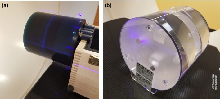
Physical phantoms for characterizing Halcyon image quality. (a) Catphan and (b) QUART phantom. [Color figure can be viewed at wileyonlinelibrary.com]
As a standard phantom and used by many CBCT QA‐related studies before, the Catphan 500 [shown in Fig. 3(a)] provides complete characterization of imaging performance for CBCT scanners. The Catphan consists of four modules enclosed in a 20 cm housing, including slice geometry and sensitometry module, high‐resolution module, low‐contrast module, and uniformity module. More details of Catphan can be found in the technical manual.17 It can be used for measuring the imaging system's sensitometry, uniformity, geometric accuracy, and low‐contrast sensitivity.
The QUART phantom, however, as shown in Fig. 3(b), is a relatively simplified phantom that comes with the Halcyon machine. It is expected to be used as the primary phantom for Hounsfield unit (HU) calibration and kV/MV CBCT image quality QA of the Halcyon system. It is designed to be lightweight with transparent material for easier alignment and lower manufacturing cost. The phantom is made of Acrylic (PMMA) and has a diameter of 160 mm. It contains a central, 3 cm thick module with four cylindrical holes of 15 mm diameter, including two air, one PTFE (Teflon) and one Polystyrene insert for high‐ and low‐contrast measurement with respect to PMMA. Nominal HU values of the materials are 120 HU for PMMA (body), −35 HU for Polystyrene, and 990 HU for Teflon. The QUART phantom also includes two 0.5 mm thick air gaps angled by 30° relative to the phantom axis for slice thickness measurements. Two identical, 6 cm thick homogeneous PMMA modules are inserted and used as uniformity modules. Two 6 mm thick polycarbonate plates are interfaced to both cylinder faces for stable positioning on the couch surface. It can be used to directly measure HU accuracy (PMMA, Polystyrene, Teflon, and air inserts), image uniformity (using uniformity modules), and geometrical accuracy. Compared to the Catphan and other volumetric imaging quality phantoms, the QUART phantom has a simplified design and minimum feature sets required for quantitative verification of system performance.
We acquired CBCT images with all eleven protocols by using these two phantoms, and performed image quality analysis. The analysis of Catphan‐based images was performed according to that recommended by previous publications,18, 19 which include high‐resolution and low‐resolution sensitivity, image slice thickness, image uniformity, HU accuracy, and geometric accuracy. For the QUART phantom images, in addition to the directly measurable quantities, surrogate strategies are needed to measure slice thickness, high‐ and low‐contrast resolution, which will be discussed in the following section.
2.D.2. Image quality analysis by use of QUART phantom
Strategies of measuring high‐contrast resolution
In medical imaging field, modular transfer function (MTF) is the most fundamental measurement of spatial (high contrast) resolution. MTF can be calculated from acquired images of a sharp‐edged object. Experience has shown that the best indicators of image sharpness are the spatial frequencies where MTF is 50% of its low‐frequency value (MTF50).20 MTF50 is ideal parameter for comparing the sharpness of imaging systems because image contrast is half its low frequency or peak values, hence detail is still quite visible. The eye is relatively insensitive to detail at spatial frequencies where MTF is below about 10%.
Traditional direct “high‐contrast resolution” measurements involve observing an image of a bar pattern, and looking for the highest spatial frequency (in lp/cm) where the bars are visibly distinct. This measurement, also called “vanishing resolution”, corresponds to an MTF of roughly 10–20%. Because this is the spatial frequency where image information disappears, it is strongly dependent on observer bias and hence is a poor indicator of image sharpness. Although this traditional measurement can be applied to the Catphan since it provides line‐pair pattern, there is no periodic pattern within the QUART phantom that can be used for visually measuring the spatial resolution directly. Therefore, an alternative strategy should be designed in order to perform tests with QUART phantom.
Considering the design of the QUART phantom, we proposed to measure the edge spread function (ESF) at the center slice of acrylic/air boundary of the QUART phantom (as shown in Fig. 4), and calculate the MTF curve. The spatial frequencies where MTF is reduced to 50% and 10% are quantified for evaluating the spatial resolution. We first derive the averaged edge spread data for a selected rectangular region. The derivative of the ESF is then computed to obtain the line spread function (LSF), and the discrete Fourier transform is applied to the LSF to yield the MTF. The LSF is often normalized to have an area of unity prior to calculating the MTF, resulting in MTFmax = 1.
Figure 4.
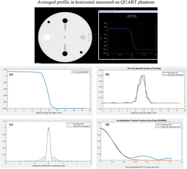
The measurement of edge spread function (ESF) and calculation of MTF for analysis of high‐contrast resolution using QUART phantom. (a) Measured ESF; (b) The corresponding calculated LSF; (c) Calculated MTF; and (d) Zoomed‐in of the calculated MTF. [Color figure can be viewed at wileyonlinelibrary.com]
Strategies of measuring low‐contrast resolution
The QUART phantom does not contain structures with varied size and CT number differences for visual assessment of low‐contrast resolution. The Polystyrene insert (opposite the white Teflon insert) of the QUART phantom in the Acrylic body represents the structure with the smallest HU step in the phantom, and this insert can be visible in all CBCT modes. Considering this, we proposed to use a quantitative evaluation of a CNR ratio between the Polystyrene insert and the Acrylic body as a surrogate of low‐contrast resolution.
The measurement procedure is shown in Fig. 5. By using the histogram tool provided on Halcyon console, an region of interest (ROI) inside the Polystyrene insert and one next to it can be delineated. The CNR can be calculated with the following formula,
where the noise can be obtained from the standard deviation (SD) values of the histogram statistics of background (Acrylic). This CNR value can be used to compare different CBCT modes or evaluate change from baseline values for satisfying the QA requirements. As an alternative strategy, the noise in the given ROI can be measured. The calculated signal‐to‐noise‐ratio (SNR) of ROI within acrylic insert, SNRA, can also be used as a surrogate of low‐contrast measure. Both CNRP/A and SNRA are reported in this study.
Figure 5.
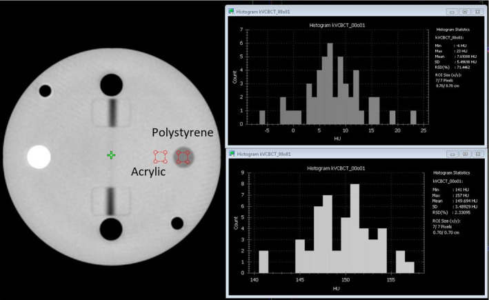
Steps of measuring low‐contrast resolution with the surrogate strategies. [Color figure can be viewed at wileyonlinelibrary.com]
Strategies of measuring slice thickness
The traditional approach to measure the slice thickness with Catphan is to measure the full width of half maximum (FWHM) of a projection from a fine structure with a specific incline angle θ. The measured slice thickness, s, can be calculated by the following Eq. (1),
| (1) |
While a fine structure, such as a wire, is available in the Catphan, a relatively large air gap is used in the QUART phantom. This module provides a visible structure for slice thickness measurement on MV CBCT images but created uncertainties (blurriness) when used to measure slice thickness on kV CBCT images. Therefore, we presented two approaches to determine FWHM: one measures FWHM with post processing on averaged profiles derived across the gap projection and the other visually measure the FWHM after creation of a binary image.
For the first method, the averaged area profile across the gap projection was derived as shown in Fig. 6(a) and the FWHM was determined based on this profile as shown in Fig. 6(b). In this case, the FWHM is 4.9 mm and the incline angle is 30° as described before. Therefore, the slice thickness is calculated as 2.8 mm (vs 2.5 mm as expected).
Figure 6.
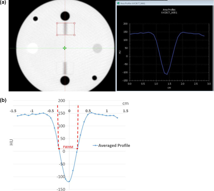
Steps of determine slice thickness based on FWMH analysis on HU profile cross the air gap projection on QUART Phantom. (a) Averaged HU profile across the air gap projection. (b) FWHM is determined based on the profile. [Color figure can be viewed at wileyonlinelibrary.com]
For the second method, the blurriness of the gap needed to be reduced in order to visually determine the width of the projection directly without post processing. For images scanned with a specific protocol, the central slice, which displays the air gap, was first selected as shown in Fig. 7(a). An ROI is placed to cover the air gap in the QUART phantom without extending to the adjacent air insert (the black circle) to obtain the minimum HU value (min). Similarly, an ROI is placed on the background region (Acrylic) to obtain the mean HU value (mean). By adjusting the window width to 1 and window level equal to (min + absolute value (min − mean) × 0.5), a binary image is generated. A maximum ROI covering all the visible dark region (ROI1) and a minimum ROI covering just within the visible dark region (ROI2) were determined, respectively [as shown in Fig. 7(b)]. The slice thickness can be measured as the average of the horizontal lengths of these two ROIs. In the example shown in Fig. 7, the HUmin = −151 and HUmean = 140; therefore, the window width should be set to 1 and window level to −5.5. On the binary images, the horizontal length of ROI1 and ROI2 are 5.1 mm and 3.6 mm, respectively. The averaged horizontal length of two ROIs is 4.35 mm, therefore the slice thickness, calculated using the formula above, is 2.51 mm (vs 2.5 mm as expected). In addition, the vertical length of the air gap displayed on all images should be equal to a fixed physical length of 2 cm. Although this quantity is irrelevant to the slice thickness measurement, this measurement can be used as an overall consistency check across protocols.
Figure 7.
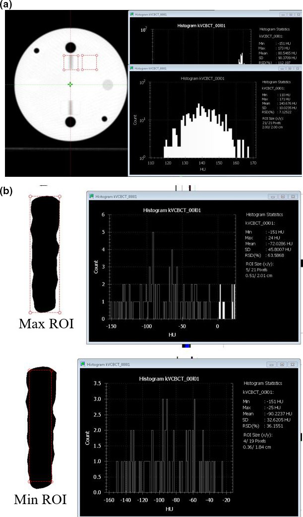
Steps to estimate slice thickness based on direct visual measurement with QUART Phantom. (a) Determination of HUmin and HUmean to calculate the window/level for direct visual measurement. The minimum HU is determined from region of interest (ROI) over the air gap projection region and the mean HU is determined from background region. (b) Drawing of max ROI covers the all dark region and min ROI covers only inside of the dark region. [Color figure can be viewed at wileyonlinelibrary.com]
2.E. kV x‐ray tube parameter measurement
The x‐ray tube tests were performed with RaySafe Unfors Xi system (Unfors RaySafe AB, Billdal, Sweden). Parameters of x‐ray tube, such as kVp, exposure, and time, were measured and compared to the programed value. A total of nine settings with four tube voltage (80, 100, 125 and 140 kV) and various mAs values were tested.
2.F. Dosimetry measurement
The computed tomography dose index (CTDI) phantom and the Unfors Xi CT detector, including an ion chamber with a 10 cm active length and a built‐in bias voltage, were used in this study for kV volumetric imaging dose measurement. The CTDI phantom was centered on the couch and aligned to external lasers before moving the table into the bore. The UNFORS CT detector (Unfors RaySafe AB) was connected to the UNFORS base unit and the detector was positioned inside the center CTDI phantom cavity. All other cavities were plugged with acrylic cylinders. Readings were taken in the phantom for each protocol at the center and four peripheral positions. The 16 cm head phantom was used for Head, Head Low Dose, Image Gently and Image Gently Large protocols; while the 32 cm body phantom was used for the remaining seven protocols. The measurements were performed with the default kVp and mAs settings in clinical mode as that shown in Table 1 and compared to the value reported by the vendor.
2.G. Feasibility of clinical implementation
Although the main purpose of this study was to characterize machine performance, a few examples of real patient images were also presented to demonstrate feasibility of clinical implementation of this system. An imaging trial on human subjects was approved by an institutional review board. Patients undergoing radiation therapy in our department were recruited for the preliminary qualitative study. Scans on pelvic site and abdominal site were performed and shown as examples as the feasibility study. The Pelvis Large protocol was used to image the pelvic site and patient was instruct to breath normally; the Pelvis Large Fast protocol was used to image the abdominal site and the patient was instructed to hold breath at end exhalation. Default kV and mAs settings and maximum scan range were used for both cases. These images were used for qualitative evaluation only in this study.
3. Results
3.A. Volumetric imaging acquisition and reconstitution time
A total of 19 image datasets were successfully acquired using the default settings under the 11 protocols with both FDK and iCBCT (when available). Operation was found to be straight‐forward and the process was efficient with preset values. Figure 8 shows both image acquisition time and reconstruction time of each imaging protocol. The Pelvis Large Protocol has the longest acquisition time of 42 s; the Head, Head Low Dose, Image Gently, Image Gently Large, Thorax Fast, and Breast protocols have the shortest time of approximately 17 s. The measured acquisition times for all protocols were within 2 s of the values reported by the vendor. Both the FDK and iCBCT had the same acquisition time, but the iCBCT option had an increased reconstruction time of, on average, 7.7 s longer than for FDK reconstruction. The iCBCT reconstruction time is longer for low‐dose scans such as Head, Head Low Dose, Image Gently, and Image Gently Large compared to the high dose scan. The overall imaging times (acquisition + reconstruction) are well below 60 s for most of the protocols, compared to that as the average of CBCT protocols on a C‐arm LINACs.
Figure 8.
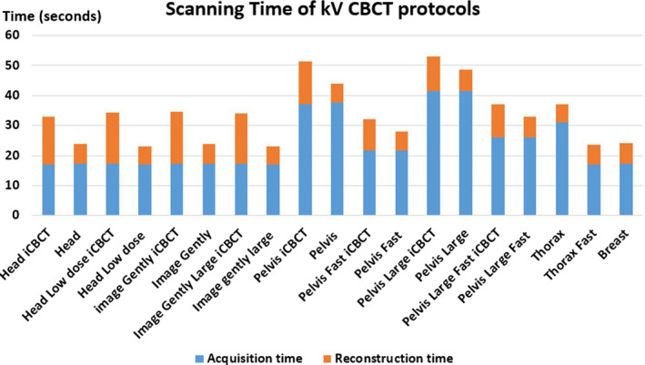
Scanning and reconstruction times of all available CBCT protocols. [Color figure can be viewed at wileyonlinelibrary.com]
3.B. Overall machine performance
The summarized machine performance results and the tolerances used are shown in Table 3. The tolerance settings are either provided by vendors or defined according to the AAPM task group reports. Overall all test results were within tolerance.
Table 3.
Tests performed to characterize kV‐IGRT system and suggested tolerances
| Detailed tests | Test results | Suggested tolerances | |
|---|---|---|---|
| Mechanical accuracy |
|
<1 mm | 1 mm |
|
<0.2 mm | 0.5 mm | |
|
<1.7 mm | 2 mm | |
| Geometric accuracy |
|
<1 mm | 2 mm |
| Patient setup accuracy |
|
<0.5 mm | 1 mm |
| Image quality tests (regular and iCBCT reconstructions on all protocols) |
|
C: ≥5 lp/cm | C: not worse than 5 lp/cm |
| Q: per protocol (0.25–0.68 cycles/mm) | Q: per protocol | ||
|
C: all HU inserts are visible | C: all HU inserts are visible | |
| Q: per protocol (2–20 for regular CBCT) | Q: >2 | ||
|
C: ±30 HU | ±40 HU | |
| Q: ±30 HU | |||
|
C: ±50 HU | ±50 HU | |
| Q: ±50 HU | |||
|
C: <0.5 mm | 0.5 mm | |
| Q: <0.5 mm | |||
|
<1 mm | 1 mm | |
| Dosimetry |
|
<20 mGy within specs | Per protocol (1–40 mGy) |
|
<20 mGy within baseline | Per protocol (1–40 mGy) | |
In the table, C represents the measurements with the Catphan phantom, and Q represents the measurement with the QUART phantom.
3.C. Mechanical, geometric, and patient setup accuracy
As described above in Section 2.C, the kV images derived from the Drum phantom are automatically analyzed via MPC software. The kV imager projection offset and field size deviations for a 4‐month period are illustrated in Fig. 9. It demonstrates that the imager projection offset is well within the tolerance of 0.5 mm and the field edge is within 1.7 mm. The geometric accuracy test and patient setup test are similar to those performed on C‐arm LINACs. For geometric accuracy, the imaging coincidence was within 1 mm at all four angles. The measured couch 3D shifts after automatic matching from a volumetric kV CBCT scan were measured within 0.5 mm along each direction, indicating a good 3D Volumatic match accuracy.
Figure 9.
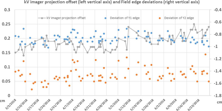
MPC results on kV imager projection offset and field edge measurement over a 4‐month period. [Color figure can be viewed at wileyonlinelibrary.com]
3.D. Volumetric imaging quality tests
3.D.1. CT number accuracy and uniformity
Figure 10 shows the CT number accuracy of all scanning protocols on the Catphan phantom. All HU values were within ±50 HU. The largest variation was observed for Teflon using Pelvis Large protocol, but still within the manufacturer‐specified tolerance. The HU deviations from the standard values between FDK and iCBCT were similar, with a noted improvement of HU accuracy for the Image Gently and Head Low Dose using iCBCT. Similar results were observed on the QUART phantom (not shown here) with all HU values well within ±40 HU. An important part of that variation is related to the simplification of assuming equal nominal HU values of the materials for all kV energies. If the energy dependency was taken into account, the nominal HU value for Teflon, for instance, would have to be lower for scans at 140 kVp than for 80 kVp, which is visible when comparing the HU errors of the Image Gently mode (80 kV) with the Pelvis Large mode (140 kV) in Fig. 10(b).
Figure 10.
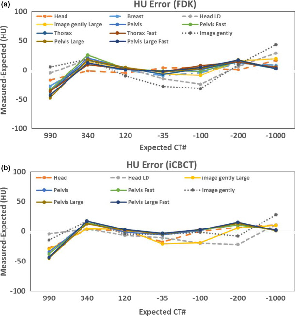
HU offset (measured HU minus expected HU) using Catphan. Standard HU value: Teflon (990), Delrin (340), Acrylic (120), Polysterene (−35), LDPE (−100), PMB (−200), Air (−1000). (a) Filtered back projection reconstruction for all available kV CBCT scanning protocols. (b) Iterative reconstruction for eight available protocols. [Color figure can be viewed at wileyonlinelibrary.com]
3.D.2. High‐contrast resolution measurements based on QUART phantom
For all protocols, the high‐contrast resolution was better than 5 lp/cm when directly measured with the line‐pair patterns on the Catphan. For the QUART phantom, the results of MTF50 from all protocols are shown in Fig. 11 below. The spatial resolution depended on both pixel size and imaging parameters. It ranged from 0.37 cycles/mm for Head protocols to 0.24 cycles/mm for Pelvis protocol and resolution was similar in both directions. The iCBCT tended to have slightly higher resolution than the regular CBCT. As mentioned in Figs. 4(b) and 4(c), the MTF is to a large degree limited by the reconstruction pixel size (rather than by the resolution of the imaging hardware), especially for the modes with the largest reconstruction diameter. For Image Gently, Head and Head Low Dose, the reconstructions have a pixel size of 0.55 mm, the Image Gently Large 0.75 mm, and all other modes 0.96 mm. With these values, the reconstruction pixel size is the most important factor limiting MTF. Figure 11 confirms the relation between pixel size and MTF50.
Figure 11.
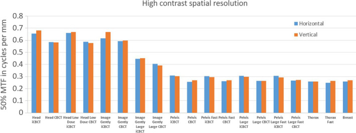
High‐contrast spatial resolution presented as 50% of MTF (MTF50) for all protocols and with QUART phantom. [Color figure can be viewed at wileyonlinelibrary.com]
3.D.3. Low‐contrast resolution measurements based on QUART phantom
For the QUART phantom, the CNRP/A and SNRA are shown in Fig. 12, which demonstrates the increase in CNR and SNR with increasing dose by use of both FDK and iCBCT. For protocols with the iCBCT option available, the SNR on iCBCT‐based images increases about 200–500% compared to the FDK‐based images yielding the same imaging dose. This observation is especially useful for the low‐dose protocols where image noise is the key limiting factor to obscure the clinical use of the acquired image. The measured SNR or CNR can also be used as baseline for future QA.
Figure 12.
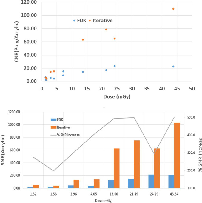
Top panel CNRP/A and bottom panel signal‐to‐noise‐ratioA as a function of kV CBCT imaging dose (used for various protocol) for two different reconstruction techniques, FDK (blue) and iCBCT (orange). [Color figure can be viewed at wileyonlinelibrary.com]
3.D.4. Slice thickness measurements based on QUART phantom
The slice thickness, as derived by use of both methods described in Section “Strategies of measuring slice thickness”, is shown below in Fig. 13. All results were within ±0.5 mm tolerance. Both approaches provide consistent results, but the HU profile method tended to overestimate the slice thickness and the direct visual measurement of FWHM based on binary images tended to underestimate the quantities slightly.
Figure 13.
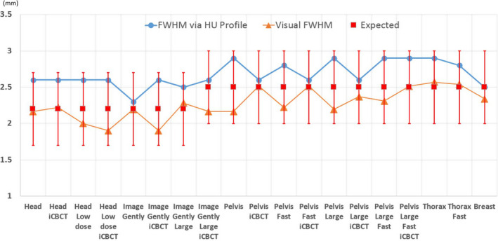
Slice thickness (y axis in the plot) measured using the two approaches described in Section 2.D.2. The blue line with circles represents the FWHM measured with HU profile; the orange line with triangle markers represents the FWHM derived directly based on visual measurement; the red squared represents the expected values ±0.5 mm tolerance. [Color figure can be viewed at wileyonlinelibrary.com]
3.E. X‐ray tube test
Table 4 summarizes the results of x‐ray tube parameter measurement. For the tested kVp and mAs settings, the tube voltage is within ±2 kV; the exposure time is within 2.5 ms. The direct measurement of tube current is not feasible and we report the total mAs settings used.
Table 4.
X‐ray tube parameter test
| Settings | Total (mAs) | Expected (kVp) | Measured (kVp) | Expected time (ms) | Measured time (ms) |
|---|---|---|---|---|---|
| 1 | 2.5 | 80.0 | 81.6 | 50.0 | 50.3 |
| 2 | 0.4 | 80.0 | 78.8 | 20.0 | 22.1 |
| 3 | 2.5 | 100.0 | 99.1 | 50.0 | 51.2 |
| 4 | 0.3 | 100.0 | 99.6 | 10.0 | 12.0 |
| 5 | 2.5 | 125.0 | 123.1 | 50.0 | 51.9 |
| 6 | 0.6 | 125.0 | 124.2 | 10.0 | 11.8 |
| 7 | 2.5 | 140.0 | 138.0 | 50.0 | 52.2 |
| 8 | 1.0 | 140.0 | 140.8 | 10.0 | 10.3 |
| 9 | 2.0 | 140.0 | 138.9 | 20.0 | 20.3 |
3.F. Radiation dose measurement
Figure 14 shows the comparisons between measured CTDI data and reported data in the protocol definitions. The vendor‐provided data assumed a perfect linearity with total mAs, which leads to an underestimation for imaging protocols with low settings of mAs/projection. This is the main reason that our measurement is slightly higher than the reported values, especially on Head Low Dose protocol and Breast protocol. In addition, CTDI measurements tend to have some systematic differences, depending on the variations of phantom and chamber setup and/or other measurement details. The fast scans yield half of the dose compared to the regular scan on pelvis protocols, and are only about 10% lower for thorax fast protocol. The “Large” protocols yield higher CTDI values due to the higher mAs settings. The measured results also demonstrated that comparable measurement results were obtained under both service mode and clinical mode.
Figure 14.
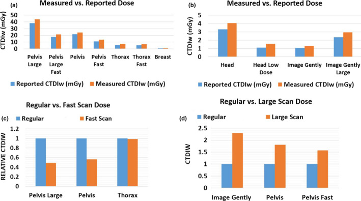
Imaging dose measurement with CDTI phantoms. (a) Measured vs reported dose on Halcyon with computed tomography dose index (CTDI) body phantom. (b) Measured vs reported dose on Halcyon with CTDI head phantom (c) Comparison of imaging dose between regular and fast scan protocols. CTDIW is normalized to regular scan. (d) Comparison of imaging dose between regular and large scan protocols. CTDIW is normalized to regular scan. [Color figure can be viewed at wileyonlinelibrary.com]
Additionally, Fig. 15 shows the comparison of imaging dose across three different Varian LINACs. Again, comparable results across machines were observed for Head and Pelvis protocols which are two protocols available on all LINACs.
Figure 15.
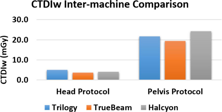
Inter‐machine imaging dose comparison on Head and Pelvis protocols. [Color figure can be viewed at wileyonlinelibrary.com]
3.G. Preliminary results on clinical patients
Within the clinical mode, the overall process was found to be smooth and efficient. Figure 16 shows the Halcyon kV CBCT images for pelvic and abdominal site. Although some streaking artifacts are presented in the CBCT images, the overall image quality is visually similar to those acquired on a multislice CT simulator. For the abdominal site, CBCT images acquired on TrueBeam are also presented. Due to the limitation of slow gantry motion, the images derived on TrueBeam were from free‐breathing scans. Fewer visual artifacts are noticeable in the Halcyon images, likely due to a combination of motion control and imaging system differences. Notice that the duodenum was visible on Halcyon images and was contoured (the blue structure) by a physician on this CBCT dataset. The fast gantry motion allows single‐breath breath‐hold CBCT imaging, which not only reduces the artifacts for localization purpose but also has the potential to be used for online structure delineation.
Figure 16.
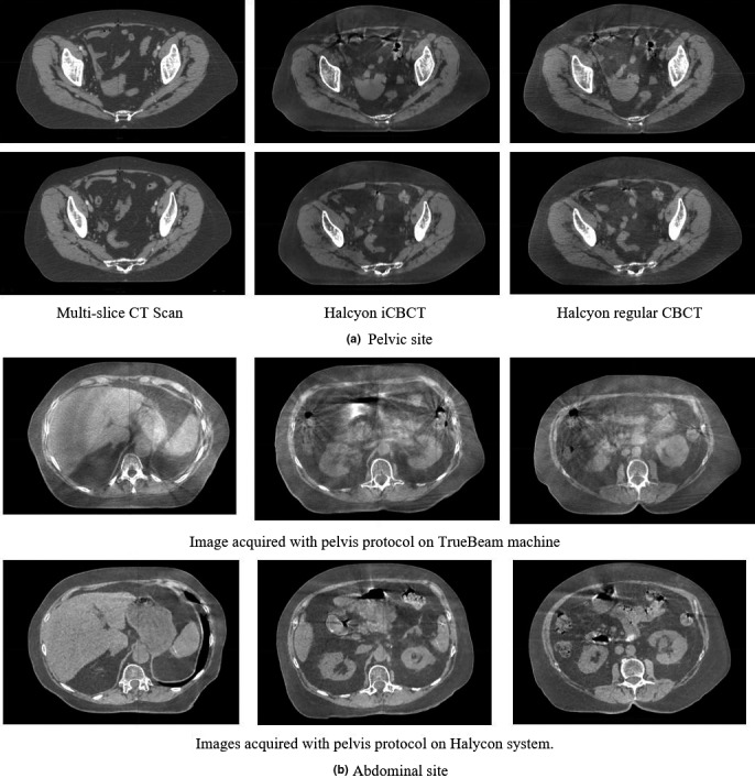
(a) The acquired pelvis images from both multislice CT scanner and Halcyon LINAC. Left column: multislice CT scans; middle column: Halcyon CBCT scans with pelvis large protocol; right column: Halcyon iCBCT scans with pelvis large protocol. (b) The acquired abdominal CBCT images from TrueBeam LINAC with free breathing and on Halcyon LINAC with breath‐hold on expiration (using Pelvis Large Fast protocol with 25 s scan time). Left, middle, and right are difference slides but from the same scan.
4. Discussions
We have characterized the performance of the kV‐IGRT system available on a preclinical Halcyon 2.0 LINAC. In summary, the system has a rapid kV volumetric imaging acquisition, simple operational process, and meets or exceeds recommended mechanical and geometric accuracy, and image quality requirements and specifications. Currently, there are no reports available to describe this kV‐IGRT system or evaluate performance. The performed tests and QA criteria used in this work were mainly adapted from AAPM guidelines and vendor recommendations. Individual institutions might have different testing or QA policies, the purpose of this work to potentially provide reference results for system benchmarking across different centers. Compared to the previously available MV imaging function on the Halcyon 1.0 system, the addition of kV imaging likely provide better soft tissue contrast and improved visualization, which could provide additional information to support clinical decision‐making but also could, potentially, enable adaptive radiation therapy on this system. Quantifying the performance of these eleven kV protocols and establishing QA procedures are the focus of this study; however, the strategies and procedures here can also be applied to MV modules with adjustments on tolerance values.
For image quality testing, we performed measurements by use of the newly released QUART phantom which comes with the Halcyon LINAC as well as the standard Catphan phantom which has been widely used and previously provided for C‐arm Varian LINACs. The results obtained on both phantoms in this study are within either AAPM guidelines or vendor‐recommended specifications. The QUART phantom is easy to handle and has low cost. However, compared to Catphan phantom, QUART phantom lacks modules for direct visual assessment of some imaging features, for example, modules for visual assessment of line‐pair visibility, low‐contrast resolution and fewer number of HU accuracy inserts. Therefore, we innovatively developed alternative strategies to measure spatial and low‐contrast resolution with QUART phantom. Potentially, phantoms from various other vendors can also be used for the tests if they satisfy the measurement requirements. Surely, the baseline for those phantoms needs to be established as well, including the appropriate QA procedures. We also evaluated the performance of iCBCT via basic image quality metrics in phantom. The iCBCT reconstruction tended to improve the SNR and CNR by reducing noise without sacrificing other image quality metrics. However, according to the algorithm, iCBCT is not designed to reduce motion artifacts and metal artifact.
As demonstrated in the patient images, the fast CBCT protocol allows volumetric image acquisition within a single breath‐hold. The rapid gantry movement potentially enables both breath‐hold imaging and delivery, which can reduce motion artifact and potentially ease motion management requirements. The preliminary patient images also indicated that (a) the breath‐hold images are feasible with the fast protocol on Halcyon and (b) a superior image quality to free‐breathing imaging could be achieved based on the initial qualitative assessment. Different to the focus on machine characterization of this paper, a more comprehensive and quantitative study will need to be conducted for patient imaging quality improvement and CBCT‐based delineation accuracy in the future.
Compared to Varian C‐arm LINACs, the Halcyon kV CBCT images have a larger FOV and longer scan range than those on TrueBeam and Trilogy (e.g., Halcyon pelvis FOV 49.2 cm with a maximum scan range of 25.4 cm vs TrueBeam pelvis half Fan scan FOV 46.5 cm with a maximum scan range of 17.6 cm). Even the slowest protocol on Halcyon is faster than the 60‐s scan on C‐arm Varian LINACs. The use of high grid ratio anti‐scatter grid (15:1 on Halcyon vs 10:1 on Varian TrueBeam) greatly reduced the scatters from patient into the imager and improved the quality of the raw image data. Besides the large FOV, rapid acquisition, reduced noise, the preset protocols, and user‐friendly interface further simplifies the operation process and make the machine more suitable for a resource‐thin setting or a busy clinic. Except the factors mentioned above, all other major image quality metrics measured with Catphan as well as the kV imaging dose measured on Halcyon are comparable to those measured on Varian C‐arm LINACs.
Our future work will focus on the long‐term stability test of this system and potential measurement on multiple Halcyon 2.0 LINACs for consistency test. A delineation study based on patient kV CBCT images derived on Halcyon is currently underway. Motion artifacts and truncation artifacts (for large patients) will also be investigated in the future work.
5. Conclusions
The performance of the kV‐IGRT system on Halcyon 2.0 was characterized with multiple image quality phantoms following national guidelines and vendor recommendations. Overall, all system tests met or exceed recommendations. The designed testing procedures and results presented in this study can provide a reference and baseline for future Halcyon imaging system testing. Fast imaging protocols make it possible to acquire single‐breath breath‐hold CBCT images, which have the potential to streamline image guidance and motion management. iCBCT demonstrated image quality with reduced noise level and can potentially improve the soft tissue visualization on some patients. In summary, iCBCT and fast imaging acquisitions are suggested for average size patients while caution should be taken when scanning large patients with these techniques.
Contributor Information
Bin Cai, Email: bcai@wustl.edu.
Hua Li, Email: li.hua@wustl.edu.
References
- 1. Torre LA, Bray F, Siegel RL, Ferlay J, Lortet‐Tieulent J, Jemal A. Global cancer statistics, 2012. CA Cancer J Clin. 2015;65:87–108. [DOI] [PubMed] [Google Scholar]
- 2. Institute, N. N. C. Cancer Statistics . https://www.cancer.gov/about-cancer/understanding/statistics.
- 3. Tyldesley S, Delaney G, Foroudi F, Barbera L, Kerba M, Mackillop W. Estimating the need for radiotherapy for patients with prostate, breast, and lung cancers: verification of model estimates of need with radiotherapy utilization data from British Columbia. Int J Radiat Oncol Biol Phys. 2011;79:1507–1515. [DOI] [PubMed] [Google Scholar]
- 4. Barton MB, Jacob S, Shafiq J, et al. Estimating the demand for radiotherapy from the evidence: a review of changes from 2003 to 2012. Radiother Oncol. 2014;112:140–144. [DOI] [PubMed] [Google Scholar]
- 5. Burridge N, Amer A, Marchant T, et al. Online adaptive radiotherapy of the bladder: small bowel irradiated‐volume reduction. Int J Radiat Oncol Biol Phys. 2006;66:892–897. [DOI] [PubMed] [Google Scholar]
- 6. Henke L, Kashani R, Yang D, et al. Simulated Online adaptive magnetic resonance–guided stereotactic body radiation therapy for the treatment of oligometastatic disease of the abdomen and central thorax: characterization of potential advantages. Int J Radiat Oncol Biol Phys. 2016;96:1078–1086. [DOI] [PMC free article] [PubMed] [Google Scholar]
- 7. Michiels S, Poels K, Crijns W, et al. Volumetric modulated arc therapy of head‐and‐neck cancer on a fast‐rotating O‐ring linac: plan quality and delivery time comparison with a C‐arm linac. Radiother Oncol. 2018;128:479–484. [DOI] [PubMed] [Google Scholar]
- 8. Li Y, Netherton T, Nitsch PL, et al. Independent validation of machine performance check for the Halcyon and TrueBeam linacs for daily quality assurance. J Appl Clin Med Phys. 2018;19:375–3822. [DOI] [PMC free article] [PubMed] [Google Scholar]
- 9. Li Y, Netherton T, Nitsch PL, et al. Normal tissue doses from MV image‐guided radiation therapy (IGRT) using orthogonal MV and MV‐CBCT. J Appl Clin Med Phys. 2018;19:52–57. [DOI] [PMC free article] [PubMed] [Google Scholar]
- 10. Wang A, Maslowski A, Messmer P, et al. Acuros CTS: a fast, linear Boltzmann transport equation solver for computed tomography scatter – part II: system modeling, scatter correction, and optimization. Med Phys. 2018;45:1914–1925. [DOI] [PubMed] [Google Scholar]
- 11. Klein EE, Hanley J, Bayouth J, et al. Task group 142 report: quality assurance of medical acceleratorsa). Med Phys. 2009;36:4197–4212. [DOI] [PubMed] [Google Scholar]
- 12. Bissonnette J‐P, Balter PA, Dong L, et al. Quality assurance for image‐guided radiation therapy utilizing CT‐based technologies: a report of the AAPM TG‐179. Med Phys. 2012;39:1946–1963. [DOI] [PubMed] [Google Scholar]
- 13. Langen KM, Papanikolaou N, Balog J, et al. QA for helical tomotherapy: report of the AAPM Task Group 148a). Med Phys. 2010;37:4817–4853. [DOI] [PubMed] [Google Scholar]
- 14. Kutcher GJ, Coia L, Gillin M, et al. Comprehensive QA for radiation oncology: report of AAPM Radiation Therapy Committee Task Group 40. Med Phys. 1994;21:581–618. [DOI] [PubMed] [Google Scholar]
- 15. Clivio A, Vanetti E, Rose S, et al. Evaluation of the machine performance check application for TrueBeam Linac. Radiat Oncol. 2015;10:97. [DOI] [PMC free article] [PubMed] [Google Scholar]
- 16. Barnes MP, Greer PB. Evaluation of the truebeam machine performance check (MPC) geometric checks for daily IGRT geometric accuracy quality assurance. J Appl Clin Med Phys. 2017;18:200–206. [DOI] [PMC free article] [PubMed] [Google Scholar]
- 17. Laboratory, T. P. The Phantom Laboratory; 2013.
- 18. Bissonnette J‐P, Moseley DJ, Jaffray DA. A quality assurance program for image quality of cone‐beam CT guidance in radiation therapy. Med Phys. 2008;35:1807–1815. [DOI] [PubMed] [Google Scholar]
- 19. Miura H, Ozawa S, Okazue T, Kawakubo A, Yamada K, Nagata Y. Image quality and absorbed dose comparison of single‐ and dual‐source cone‐beam computed tomography. J Appl Clin Med Phys. 2018;19:360–366. [DOI] [PMC free article] [PubMed] [Google Scholar]
- 20. Greer PB, van Doorn T. Evaluation of an algorithm for the assessment of the MTF using an edge method. Med Phys. 2000;27:2048–2059. [DOI] [PubMed] [Google Scholar]


