Abstract
In this study, we propose a new mounting method to improve accelerometer sensing performance in the 50 Hz–10 kHz frequency band for knee sound measurement. The proposed method includes a thin double-sided adhesive tape for mounting and a 3D-printed custom-designed backing prototype. In our mechanical setup with an electrodynamic shaker, the measurements showed a 13 dB increase in the accelerometer's sensing performance in the 1–10 kHz frequency band when it is mounted with the craft tape under 2 N backing force applied through low-friction tape. As a proof-of-concept study, knee sounds of healthy subjects (n = 10) were recorded. When the backing force was applied, we observed statistically significant (p < 0.01) incremental changes in spectral centroid, spectral roll-off frequencies, and high-frequency (1–10 kHz) root-mean-square (RMS) acceleration, while low-frequency (50 Hz–1 kHz) RMS acceleration remained unchanged. The mean spectral centroid and spectral roll-off frequencies increased from 0.8 kHz and 4.15 kHz to 1.35 kHz and 5.9 kHz, respectively. The mean high-frequency acceleration increased from 0.45 mgRMS to 0.9 mgRMS with backing. We showed that the backing force improves the sensing performance of the accelerometer when mounted with the craft tape and the proposed backing prototype. This new method has the potential to be implemented in today's wearable systems to improve the sensing performance of accelerometers in knee sound measurements.
Keywords: knee sounds, acoustic sensing, vibration analysis, biomedical instrumentation, noninvasive biosensing, accelerometer mounting, acoustic emission, materials in vibration and acoustics, sensors and actuators
1 Introduction
The knee is a modified hinge joint that consists of ligaments such as the anterior cruciate ligament (ACL) and posterior cruciate ligament, the meniscus that provides structural integrity to the knee under various mechanical loading conditions, and fat and soft tissue layers [1]. Being the largest joint, it is one of the most complex structures in the human body and plays an important role facilitating daily activities such as walking and running [2]. During such activities, knee injuries often occur among different groups including athletes, military personnel, and even sedentary population due to the lack of exercise and low muscle strength [2–4]. More than 6 million people are hospitalized every year in the Unites States due to knee-related injuries such as meniscus tears and ACL tears [5]. Knee injuries are also one of the most common causes of missed workdays [6]. Most patients need rehabilitation, and the health of the knee is typically monitored by patient surveys, subjective examination by a medical doctor, or expensive imaging techniques [7]. Subjective methods are rarely accurate, and imaging may not be easily available. Thus, an objective, accurate, and readily available knee health monitoring method can provide a substantial value.
Thus, researchers have investigated the use of vibroarthographic signals, so-called joint sounds as a means of augmenting existing methods for knee health monitoring [2]. Joint sounds represent the acoustic response to the vibrations associated with joint articulation, and they are used to derive physiological biomarkers in a variety of biomedical and biomechanical applications, including but not limited to knee health assessment [8–10]. By measuring and recording these acoustic signatures of the knee, researchers have built a better understanding of the internal dynamics of the joint [11]. Substantial work has been devoted to developing signal-processing and machine learning algorithms to discover the underlying knee health information contained in these sounds [12,13]. The accuracy of such methods depends on the quality of the recordings, which is influenced by the performance of the sensing system [9]; however, the sensing approach, and in particular the interface between the sensor and the skin have not yet been optimized from a scientific standpoint.
Accelerometers or microphones are used as the acoustic sensor modality in such devices [2,14–16]. As manufacturing technologies have been developed and accelerometers with low noise and high sensitivity have become ubiquitous, the recording quality has improved [17–19]. Even with these advancements, however, recording knee sounds have been challenging due to the low acoustic level of the signals. Acoustic impedance mismatch of the skin–air interface results in a high level of internal reflection of acoustic signals [20]. In addition, skin has frequency-dependent damping characteristics, and this damping effect is more apparent at higher frequencies [21,22]. This damping behavior precludes recording of high-frequency content extending up to 20 kHz [23]. To capture the acoustic information in a wide frequency band, a broadband and low-noise air or contact microphone should be used. Our lab previously compared air microphones and contact microphones for knee sound measurements [17]. Air microphones were shown to be more prone to background noise, while contact microphones are affected by the rubbing noise on the skin. Note that, in that study, contact microphones were attached to the skin by using only an adhesive tape that is attached on top of the microphone. To reduce background noise, contact microphones can offer more convenient sensing performance and reproducibility with a low-noise mounting method, where the rubbing noise is reduced [17].
In the literature, different methods have been described for the mounting of accelerometers on the skin. Shark used hypoallergenic medical adhesive patches for the placement of the accelerometer [24]. Chu et al. used a special soft silicone rubber with low shear resistance and a slippery surface for mounting [25]. Silicone rubber was bonded to the outer edge of the microphone, and a sterile surgical lubricant was used between the skin and the rubber. McCoy et al. used adhesive tapes that are attached on top to fix accelerometers without any control on the shape of the tapes and the pressure is applied on the accelerometers [2]. Decker et al. proposed using cyanoacrylate for this purpose [26]. Double-sided adhesive tapes have been used by researchers in acoustic measurements in biomedical applications [27–29]. However, the effect of the mounting method on the sensing performance of the accelerometer in knee sound measurements has not been studied explicitly.
In this study, we propose a new mounting method for accelerometers to acquire knee sounds with improved quality in the 50 Hz–10 kHz frequency band. The choice of the frequency band is governed by the facts that (1) the reported knee sound characteristics suggests that most of the power is below 10 kHz [17] and (2) the frequency bandwidth of the accelerometer used in this study is 10 kHz. We propose that the backing force can improve the sensing performance of the accelerometer in knee sound measurements. We performed a parametric study with five different mounting materials and four different backing tapes. The effect of the backing force level on sensing performance was also investigated in a custom-designed test setup. The vibration model of the setup was studied, and the measurements are compared with the transfer function calculated for the model. The results of the parametric study informed the design of a prototype capable of enhancing the sensing ability of the accelerometers to measure the knee sounds. A proof-of-concept human subjects study was designed to validate the results of the parametric study and to show the improvement in the sensing performance with the custom-designed backing prototype.
2 Methods
In this section, the methodology used in this study is discussed. First, the test setups for the parametric study and their vibrational model are presented. Then, the details of the backing prototype design are described, and the protocol of a proof-of-concept human subjects study is presented. Finally, signal-processing and data analysis methods are explained.
2.1 Parametric Study for Accelerometer Mounting.
To find the best mounting method for improved sensing performance of the accelerometer on the skin, we performed a parametric study. First, the effect of mounting material on sensing performance was investigated. For that purpose, five different mounting materials were used. Then, noise performances of different backing tapes were studied. The results of the mounting material and backing tape selections were used to construct a backing force analysis setup. Five different levels of the backing force were applied through a custom-designed test setup. Finally, the vibration model of mounting material selection and backing force analysis setups are presented.
2.1.1 Mounting Material Selection.
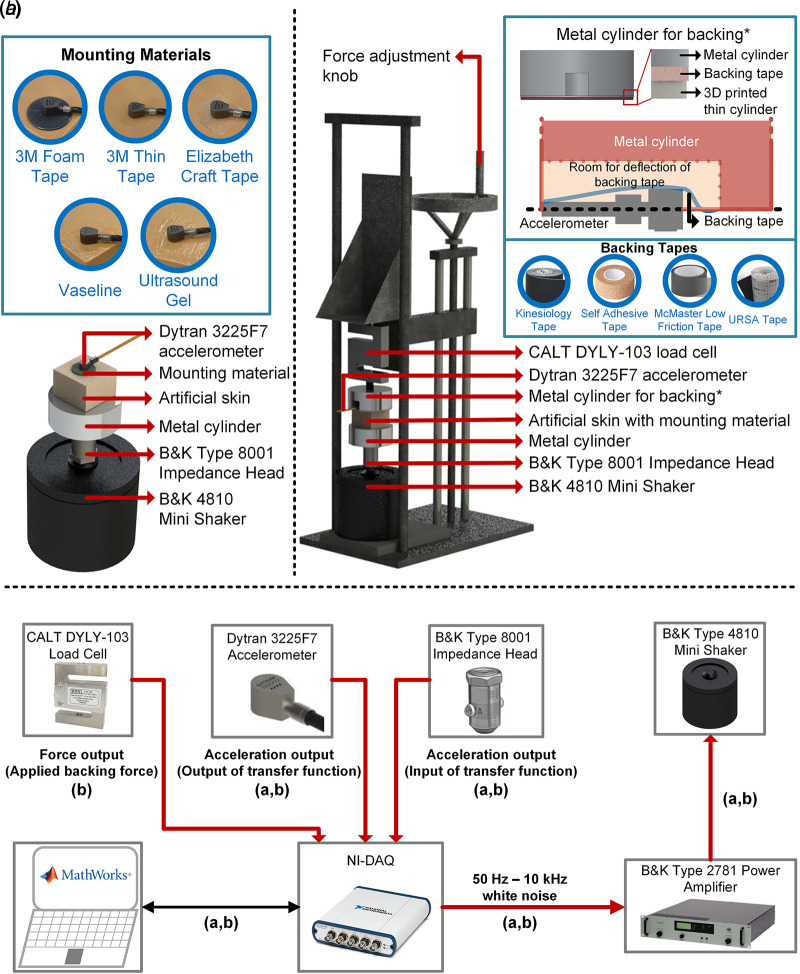
The effect of mounting material on the performance of the accelerometer was investigated by the setup shown in Fig. 1(a). To study the different mounting materials, we analyzed the resultant transfer functions. A Type 4810 electrodynamic mini shaker (Brüel & Kjær, Denmark) was used as the excitation source. The frequency range of the shaker is from direct current up to 18 kHz, which covers the frequency range of interest, 50 Hz–10 kHz. A 3225F7 uniaxial accelerometer (Dytran Instruments Inc., Chatsworth, CA) was used as the output of the system, which had been calibrated 3 months before the start of this study. The sensitivity of the accelerometer is 100 mV/g in the 50 Hz–10 kHz frequency band. The input acceleration was measured by a Type 8001 impedance head (Brüel & Kjær, Denmark) that was fixed on the shaker. The sensitivity of the impedance head is 30 pC/g, and it was connected to a Type 2647-D charge to constant current live drive converter (Brüel & Kjær, Denmark) with 1 mV/pC sensitivity in 50 Hz–10 kHz frequency band. An 8 mm thick skin-like component (Sawbones, WA) was used to simulate the human skin. To accommodate the skin patch on the shaker, a metal solid cylinder was fixed on the impedance head, increasing the contact surface. Then, the skin patch was glued on the metal cylinder on the impedance head using cyanoacrylate adhesive.
Fig. 1.
Test setups for (a) mounting material selection and (b) backing force analysis. (c) Electrical connections in setups (a) and (b).
In the literature, double-sided and adhesive tapes have been used to attach accelerometers on the skin in different biomedical applications [2,24–29]. In this study, five different mounting materials were selected as follows: (1) 3M 200MP foam double-sided tape and (2) 3M double-sided thin tape (3M Company, MN), (3) double-sided craft tape (Elizabeth Craft Designs, Inc., CO), (4) ultrasound gel (Thera Sonic, USA), and (5) Vaseline (Blueseal, IA). Ultrasound gel was included since it is widely used by the medical community in ultrasound imaging as a mechanical couplant [30,31]. Conversely, Vaseline was chosen due to its availability and relatively thick viscosity compared to ultrasound gel, which can be useful when fixing the accelerometer on skin.
As the excitation, a 3-s, 66% duty cycle (2-s excitation, 1-s no excitation) subsequential digital white noise with 50 Hz–10 kHz bandwidth was generated in matlab (The MathWorks, MA) with a total duration of 60 s. A USB-4431 data acquisition unit (DAQ, National Instruments, TX) with four analog inputs and one analog output was employed to collect data. The output of the DAQ was used to excite the shaker, and the shaker was connected to a Type 2781 power amplifier (Brüel & Kjær, Denmark). The outputs of the accelerometer and impedance head were connected to the input ports of the DAQ and sampled at 50 kHz.
2.1.2 Backing Tape Selection.
We hypothesized that the application of backing force can improve the sensing performance of the accelerometer in this application. When the backing force is applied using tape, the tape can generate rubbing noise due to nonzero friction on the contact surface with the accelerometer. In the literature, researchers have used Kinesio tape and self-adhesive tapes as backing tapes to attach accelerometers on the skin [17,24]. We selected the Kinesio tape, self-adhesive tape, URSA tape (URSA, UK), and ultra-low friction tape (McMaster-Carr, IL) for this analysis. URSA tape was included in this study due to its smooth surface, which would have potentially offered a low-noise solution to the problem. Low-friction tape was used due to its potential for low-noise performance. We also proposed that we could combine low-friction tape with other backing tapes—i.e., we could mount the adhesive-lined part of low-friction tape to the corresponding part of the other tape. In this way, we could still use Kinesio, self-adhesive, or URSA tape, while the low-friction tape could offer a smoother contact surface with the accelerometer. We compared noise power spectral density (PSD) of the accelerometer for eight cases: (1) no backing tape, (2) Kinesio tape, (3) Kinesio and low-friction tapes, (4) self-adhesive tape, (5) self-adhesive and low-friction tapes, (6) URSA tape, (7) URSA and low-friction tapes, and (8) low-friction tape.
For the quantitative analysis of the noise generated by the backing tape, the accelerometer was glued and fixed on a metal surface, and a researcher manually wrapped backing tapes around his finger; this tape was then rubbed against the accelerometer to generate a noise analogous to the actual measurement. We used a capacitive force sensor (CS8-10N, SingleTact, CA) to monitor the applied force in real time. The force was held at 1 ± 0.1 N throughout the measurements. The output of the accelerometer was sampled by the DAQ at 50 kHz. We obtained measurements for 512 s for each case. The total recording was divided into 1024 equal intervals each being 500 ms, and averaging was applied to obtain the noise PSD.
2.1.3 Backing Force Analysis.
The custom-designed setup for the backing force analysis is shown in Fig. 1(b). As in the mounting tape selection setup, we used a mini shaker, an impedance head, a skin patch, and an accelerometer. The same excitation described in Sec. 2.1.1 was used in the backing force analysis. In addition, we designed a metal cylinder for backing to apply force on the accelerometer. We drilled a hole with 3 cm diameter and 1 cm height into a 5 cm diameter and 2 cm height metal cylinder to accommodate the accelerometer. A groove was also drilled for the cable of the accelerometer to protect it from direct contact with the cylinder. Three screw holes were drilled on the metal cylinder to fix the backing tape; however, we initially observed that tapes largely deform and tear when attached using the three screws. To address the problem, we used a 3D-printed, 2 mm thick washer. We placed the backing tape between the 3D-printed washer and the metal cylinder, and we fixed it by using the screws. With these additions, we observed no deformation in the tape under backing forces of up to 2 N.
The backing cylinder was attached to the load cell (CALT DYLY-103, China) to monitor the applied force simultaneously with acceleration measurements. The backing body (metal cylinder for backing and load cell) was attached to an adjustment knob. The position of the backing body could thus be adjusted by moving the knob.
Electrical connections for the backing force analysis are shown in Fig. 1(c). The load cell is connected to the DAQ through an in-line adapter (Honeywell, OH). Before each measurement, the force level was adjusted and thereafter recorded during the measurements to detect possible deviations in time. We selected two mounting methods: (1) craft tape and (2) Vaseline, and three backing tapes: (1) low-friction tape, (2) Kinesio and low-friction tapes, and (3) self-adhesive and low-friction tapes for this analysis. The details of these decisions are presented in Sec. 3.1. We used five different backing forces: 0, 0.5, 1, 1.5, and 2 N. With backing forces greater than 2 N, we observed that backing tapes started to deform, hence obtaining a constant level of the backing force became unattainable. In addition, as presented in Sec. 3.2, the backing force attenuates low-frequency vibrations below 1 kHz, and the attenuation would gradually increase with the increasing backing force. Although the results of the knee sounds measurements presented in Sec. 3.3 show no significant change in the recorded low-frequency signals with backing, higher levels of the backing force (>2 N) could result in the loss of this information. We thus set 2 N as the upper limit of the backing force studied.
2.1.4 Analytical Modeling.
The custom-designed setups presented in Figs. 1(a) and 1(b) are modeled as a 2-degrees-of-freedom system as demonstrated in Fig. 2. msk, ksk, and csk are the mass, stiffness, and damping of the skin patch, respectively. The adhesive tape is modeled as a massless spring-damper system of kadh and cadh, and the accelerometer is considered as the mass ma. A set of spring and damper (kb and cb) is added to the system when backing the force is applied. Due to relatively high resonant frequency (>60 kHz) of the accelerometer, its stiffness is not considered in the model. The load frame is also considered as a rigid fixed support since it is much stiffer than the skin patch and the adhesive tape. The analytical model is used to study the effects of mounting material and backing force as experimentally described in Secs. 2.1.1 and 2.1.3, respectively. For the mounting material selection study and the backing force analysis under no force condition, kb and cb are set to zero.
Fig. 2.
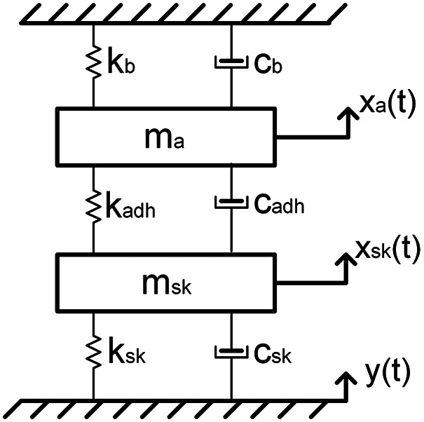
Mechanical system model of the accelerometer with the backing body
The equation of motion of the system can be expressed as follows:
| (1) |
| (2) |
where y(t) is the displacement of the base, t represents time, and xsk(t) and xa(t) are the displacements of the skin patch and the accelerometer, respectively.
The mechanical properties and dimensions of the utilized components in the model are listed in Table 1. The stiffness of the skin patch is calculated as the stiffness of a bar under axial load, and the stiffness of the backing tape is calculated as the stiffness of a simply supported beam under transverse bending force. The transfer function of the system is thus
| (3) |
where represents the imaginary unit, ω is the angular frequency, and
| (4) |
| (5) |
Table 1.
The properties and the dimensions of the materials in the setup
| Quantity | Value |
|---|---|
| Mass density of the skin patch—ρSkin patch (kg/m3) | 1215 [32] |
| Mass of the accelerometer—m2 (g) | 1 |
| Surface area of the skin patch—ASkin patch (cm2) | 16 |
| Contact area of the accelerometer with the skin patch—AAccelerometer (cm2) | 0.085 |
| Thickness of the skin patch—tSkin patch (mm) | 8 |
| Thickness of the adhesive tape—tAdhesive tape (μm) | 30 |
| Thickness of the backing tape—tBacking tape (μm) | 127 |
| Width of the backing tape—wBacking tape (mm) | 9 |
| Length of the backing tape—lBacking tape (mm) | 30 |
| Young's modulus of the skin patch—ESkin patch (MPa) | 50 [33] |
| Young's modulus of the adhesive tape—EAdhesive tape (MPa) | 0.7 [34,35] |
| Young's modulus of the backing tape—EBacking tape (MPa) | 550 [36] |
The mounting method of accelerometers can significantly alter the frequency response by modifying the effective stiffness in between the sensor and the test structure [37]. The addition of a layer of adhesive decreases the stiffness between the accelerometer and the object, which can lead to a change in the measured vibration response of the structure. Thus, the stiffness value kadh is varied in the model to investigate the effect of different mounting materials on the transfer function of the system. In addition, the effect of the backing tape (kb and cb) on the transfer function was studied. With pressure, better bonding between the adhesive and accelerometer/skin patch can be achieved. Under 2N backing force, the applied pressure on the adhesive tape can be calculated as PAdhesive = 240 kPa, and at this level, the stiffness of the adhesive tape is expected to be doubled compared to no pressure case [34,38].
2.2 Prototype Design.
The results of the parametric study, presented in Sec. 3.1, suggested that the best performance of an accelerometer is achieved when (1) it is mounted by the craft tape and (2) the low-friction tape is used as the backing tape under 2 N force. Therefore, we designed a custom 3D-printed prototype with low-friction tape to apply force on the accelerometer as shown in Fig. 3. The prototype was printed by an Ultimaker-3 3D printer (Ultimaker Inc., The Netherlands) with polylactic acid filament. A hollow space was designed inside the prototype to provide sufficient room for the deflection of backing tape. We designed a small notch on each of the two sides of the prototype for the accelerometer cable.
Fig. 3.
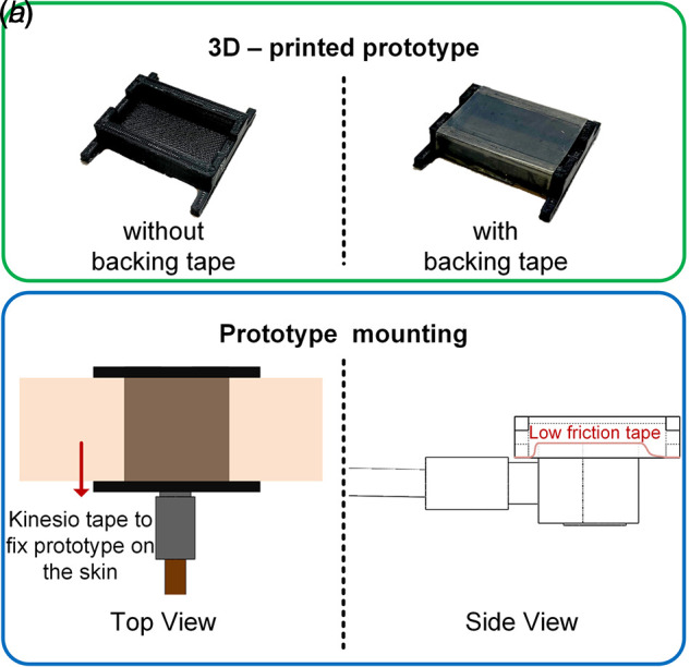
Prototype design for knee sound measurements: (a) 3D-printed prototype and (b) top and side views of the design with accelerometer
Since monitoring the force level during knee sound measurements would not be feasible, we measured the level of the backing force while the knee was not moving. We attached the backing prototype on the knee and measured the applied force with the same SingleTact force sensor in Sec. 2.1.2. The force sensor was placed between the accelerometer and the prototype. The measurement was performed 20 times by detaching and attaching the prototype with new Kinesio tape each time. The recorded backing force was 1.8 ± 0.15 N.
2.3 Knee Sounds Measurement Protocol.
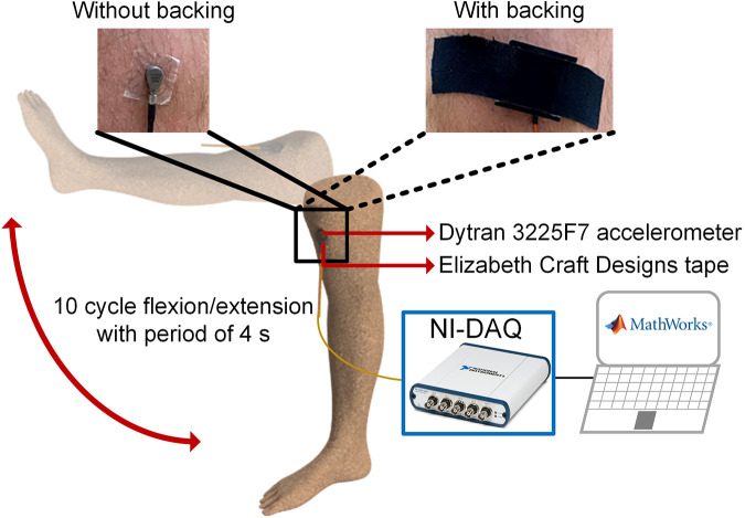
This study was approved by the Georgia Institute of Technology Institutional Review Board, and all subjects provided written consent. In this study, three female (height = 160.0 ± 0.5 cm, weight = 51.0 ± 3.0 kg, and age = 24.0 ± 3.5 years) and seven male (height = 179.0 ± 2.8 cm, weight = 73.1 ± 7.2 kg, and age = 26.9 ± 3.0 years) subjects participated. Each subject was asked to perform ten unloaded knee flexion/extension cycles with a period of 4 s. A metronome was used to guide the subjects to follow the desired pace throughout the measurements. Both the with- and without- backing cases were studied by having the subject perform the same flexion/extension exercise with both setups. Each measurement was taken three times to analyze the consistency of the measurement. The accelerometer was attached on the medial side of the patella (medial retinaculum) of each subject. This placement was selected to acquire knee sounds with minimal attenuation by soft tissue [29]. The measurement setup is shown in Fig. 4. The knee sounds were sampled by the DAQ at 50 kHz and saved on a laptop for postprocessing.
Fig. 4.
Knee sound measurement protocol and accelerometer placement with and without the backing force
2.4 Signal Processing and Data Analysis.
We used Welch's method for transfer function estimation in both the mounting material selection and the backing force analysis studies with a Hamming window with a length of 1 s and overlap of 0.7 s [39]. The acceleration output of the impedance head was used as the input x(t), and the acceleration output of the accelerometer was used as the output y(t) of the system. Both signals were bandpass filtered with 50 Hz and 10 kHz cut-off frequencies. The transfer function was calculated as follows:
| (6) |
where Pyx(f) is the cross power spectral density of the input and the output, and Pxx(f) is the power spectral density of the input.
In postprocessing of the knee sounds, we used two approaches to quantify how backing affects sensing performance: (1) we extracted two spectral features, spectral centroid frequency, and spectral roll-off frequency, and (2) we calculated two root-mean-square (RMS) accelerations by dividing the frequency spectrum into two bandwidths of 50 Hz–1 kHz and 1–10 kHz. For the remainder of this article, the 50 Hz–1 kHz frequency band will be referred to as the low-frequency band, and the 1–10 kHz frequency band will be referred to as the high-frequency band.
Spectral centroid frequency is an indication of the center of mass of the spectrum. It was calculated from the fast Fourier transform (FFT) of the signal by calculating the weighted mean as follows:
| (7) |
where N is the number of distinct frequency bins, which is half of the number of FFT points, an is the FFT coefficient of the nth frequency bin, and fn is the frequency value of nth frequency bin [40]. Spectral roll-off frequency is the 95th percentile of the power spectral distribution [40]. The changes in these spectral features can be visualized as indications of the change in frequency content of the signal.
In addition to the spectral features, we used the low-frequency band and high-frequency band RMS accelerations to observe the changes in measured power with backing. By combining these two types of features, we can potentially analyze the changes in recorded signals with backing. The signal-processing method is shown in Fig. 5.
Fig. 5.
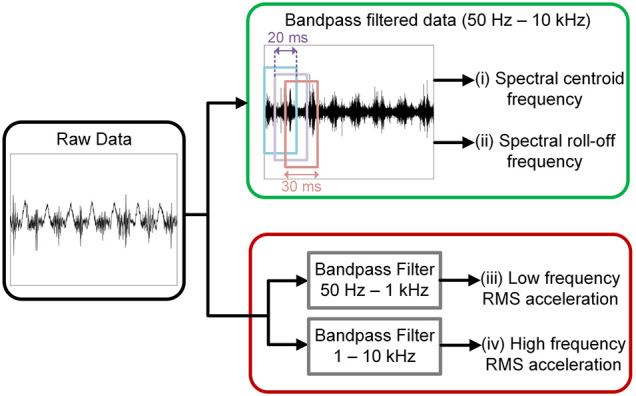
Signal-processing procedure for feature extraction from knee sound measurements
For the statistical analysis of the changes in features, we first used the Anderson–Darling test for normality [41]. We found that the data were not normally distributed, and thus, the Wilcoxon Signed-Rank test was performed for the statistical significance analysis [41]. For the analysis of consistency between measurements with backing, intraclass correlation (ICC) values of the features were calculated using average measure model (i.e., ICC(1,k)) to assess the reproducibility of the measurements. In ICC calculation, a 95% confidence interval was used [41].
3 Results and Discussion
In this section, first, the results of the parametric study are presented and discussed; this includes the results from the mounting material selection study and the backing force analysis. The response of the vibration model is presented and compared with the experimental results. Then, the results of the proof-of-concept human study are given.
3.1 Parametric Study.
The power spectrum of the input (impedance head) and the output (Dytran accelerometer) accelerations for the mounting material analysis tests are shown in Fig. 6. These data were collected for the craft tape case, which is selected as a representative case for this study. The output has a relatively flat power spectrum, while the accelerometer power spectrum drops by up to 40 dB for frequencies greater than 1 kHz as shown in Fig. 6(a). The input–output coherence of these measurements is shown in Fig. 6(b). High coherence (>0.95) in the 50 Hz–10 kHz frequency band suggests a reliable vibration measurement.
Fig. 6.
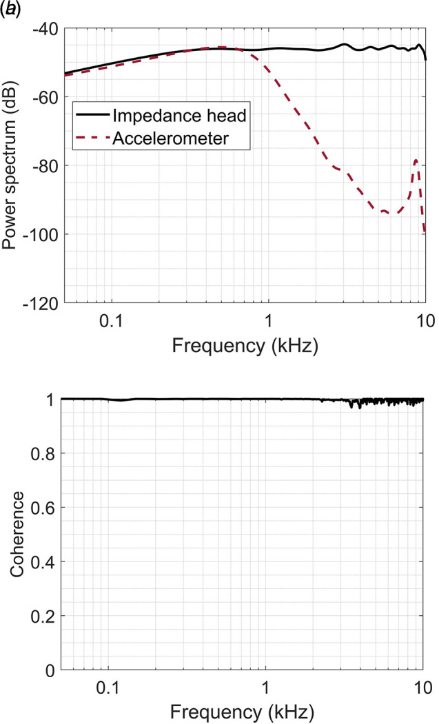
Measurement results of craft tape-mounted accelerometer under no force: (a) Welch's power spectrum of the impedance head and accelerometer outputs and (b) the coherence of the measurement
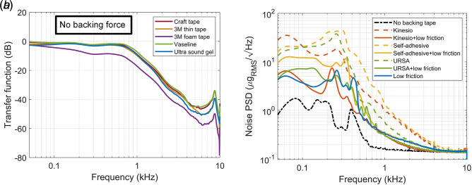
The transfer functions estimated by the method described in Sec. 2.4 for the five different mounting materials in the 50 Hz–10 kHz frequency band are shown in Fig. 7(a). We observe that the 3M foam tape presents the lowest response (12 dB lower on average in 50 Hz–10 kHz frequency band) from the studied mounting materials. This can be attributed to the greater thickness of the foam tape compared to other tapes and the damped nature of the foam material. We decided to use craft tape and Vaseline as mounting materials in the backing force analysis since they demonstrate a slightly higher response throughout the frequency band.
Fig. 7.
The results of (a) mounting tape and (b) backing tape selection tests
The noise PSDs of eight different backing tapes are presented in Fig. 7(b). We observe that the cases with low-friction tape have lower noise PSD compared to other tapes. During measurements, we also observed that URSA tape was not sufficiently elastic to be used in backing force application. With these quantitative results and practical observations, we decided to use (1) low-friction tape, (2) Kinesio and low-friction tapes, and (3) self-adhesive and low-friction tapes as the backing tapes in the backing force analysis. While low-friction tape modifies the interface of the backing material and accelerometer leading to a reduced spectral noise in all cases, Kinesio and self-adhesive tapes are still used for the next study as each material provides a different levels of elasticity.
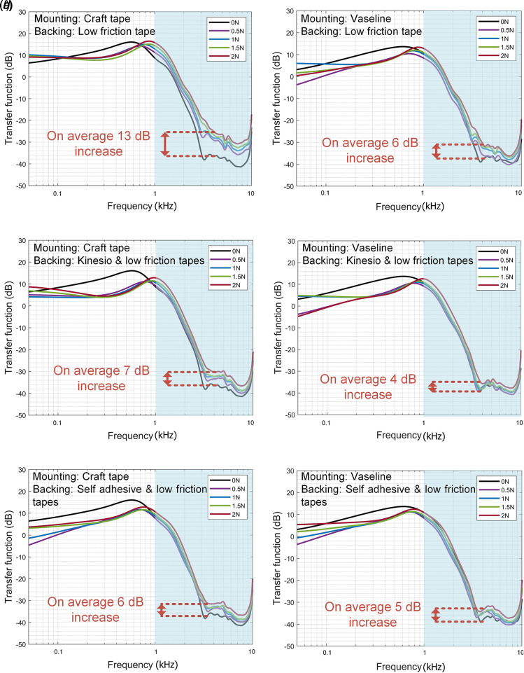
The transfer functions measured from the response acceleration are plotted in Fig. 8 for various backing and mounting methods under backing forces of 0, 0.5, 1, 1.5, and 2 N. In the high-frequency band, we observe performance improvement for all cases under backing force. The improvement is greater for craft tape compared to Vaseline with any backing tape, and it is greater for low-friction tape compared to other backing tapes with any mounting material. By using craft tape as the mounting material and low-friction tape as backing tape, in the 1–10 kHz frequency band, a 13 dB increase in transfer function is obtained at 2N backing force. As the backing force increases, we observe higher improvement in the high-frequency band. However, it is not practically feasible to increase the force more than 2N since it starts deforming the backing tape and thus impedes the ability to obtain a constant level of backing force over time.
Fig. 8.
The result of backing force analysis under different conditions: mounting material is craft tape and Vaseline with (a) and (b) low-friction tape, (c) and (d) Kinesio and low-friction tapes and (e) and (f) self-adhesive and low-friction tapes as backing tape, respectively
Overall, we showed that by using craft tape as the mounting material and low-friction tape as the backing tape under 2N backing force, a 13 dB sensitivity improvement can be achieved in the high-frequency band, while the performance in the low-frequency band experiences only a slight reduction. This mounting method has the potential to be used in knee sound measurement for improved sensing performance.
3.2 Analytical Modeling.
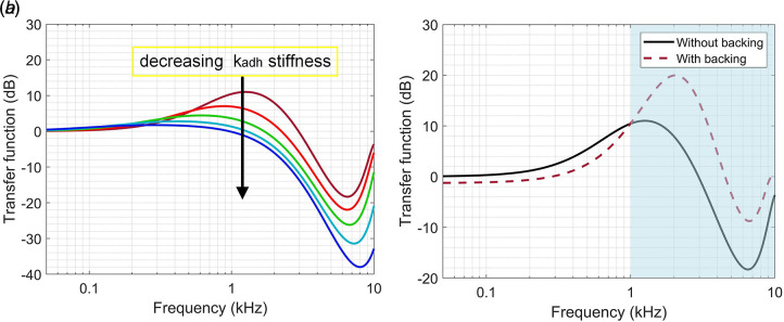
The transfer function of the modeled system in the 50 Hz–10 kHz for mounting material selection setup is plotted in Fig. 9(a). Stiffness of the adhesive is decreased by 10% steps starting from the value reported in Sec. 2.1.4. The adhesive is expected to have lower stiffness (smaller kadh) in the system when the foam tape is used due to its multilayer and thick structure. We observe a decrease in the transfer function as the stiffness of the adhesive is decreased in Fig. 9(a), which is consistent with our experimental result plotted in Fig. 7(a).
Fig. 9.
Transfer function of the vibration model for (a) mounting material selection setup with different kadh stiffness values and (b) backing force analysis without and with backing
In Fig. 9(b), the transfer function is plotted without and with backing for the backing force analysis vibration model. The low-frequency content (<1 kHz) decreases in the transfer function, while higher frequencies (>1 kHz) increase when the backing is added. This result is also consistent with the experimental results plotted in Fig. 8.
Overall, the vibration model for the experimental setup yields a consistent response with the experimental results supporting the validity of the model.
3.3 Knee Sounds Measurements.
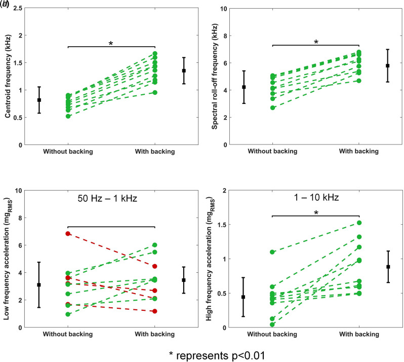
We used the custom-designed prototype described in Sec. 2.2 to record knee sounds with the protocol explained in Sec. 2.3. Spectral features and low- and high-frequency RMS accelerations were used to validate the performance of backing. The results are shown in Fig. 10. In Figs. 10(a) and 10(b), centroid frequency and spectral roll-off frequency increase with backing for all ten subjects. Mean centroid frequency increases from 0.8 kHz to 1.35 kHz, while mean spectral roll-off frequency increases from 4.15 kHz to 5.9 kHz. The differences between without and with backing cases are found to be statistically significant for both features with p < 0.01.
Fig. 10.
Results of knee sound measurements—changes in (a) centroid frequency, (b) spectral roll-off frequency, (c) low-frequency, and (d) high-frequency RMS accelerations with backing prototype
In Fig. 10(c), we observe no statistically significant difference in low-frequency RMS acceleration between without and with backing cases. Mean low-frequency RMS acceleration was found to be 3.1 mgRMS and 3.3 mgRMS without and with backing, respectively. There is also no consistent trend in this feature: it is increasing for six subjects and decreasing for four subjects. In contrast, high-frequency RMS acceleration is increasing for all subjects with backing, and the difference is statistically significant as shown in Fig. 10(d). Mean high-frequency RMS acceleration increases from 0.45 mgRMS to 0.9 mgRMS with backing.
The increase in the spectral centroid frequency implies that the center of mass of the power spectrum is shifted to higher frequencies. This can be achieved by only acquiring more high-frequency content or less low-frequency content from knee sounds. The increase in spectral roll-off frequency also indicates more high-frequency content.
Although the spectral features suggest that more high-frequency content is present in the recordings collected using the backing, they are insufficient in showing that backing does not decrease low-frequency performance and improve high-frequency performance as a counterproductive result. To address this concern, high- and low-frequency RMS accelerations were used. We observed that no statistically significant change is found when comparing the low-frequency RMS accelerations, while a statistically significant increase is found when comparing the high-frequency RMS accelerations. This suggests that we can acquire a wider range of knee sound frequency content with backing. This result is consistent with the parametric study and modeling results.
Intraclass correlation values (i.e., ICC(1,k)) of spectral centroid frequency, spectral roll-off frequency, and low-frequency and high-frequency RMS accelerations are calculated as 0.89, 0.91, 0.79, and 0.87, respectively, for the knee sounds recordings with backing. Since the ICC values are greater than 0.7, we can conclude that the measurements taken with backing are consistent for each subject, and backing does not generate a random effect on the measurement [41].
Overall, we found that backing force improves accelerometer sensing performance in knee sound measurements. To address the challenge in detecting low-level signals in knee sound measurements, the backing prototype we proposed can offer improved sensing performance. With backing, we acquire information that was not previously available without backing due to the low-amplitude nature of these sounds and the high-frequency attenuation previous sensing setups exhibited. Both power related features (e.g., RMS) and the spectral features used in this analysis have been extensively used in knee health informatics for the purpose of classifying healthy and injured knees [12]. This increased sensing performance can improve the classification accuracy in these applications, which provide clinically relevant information about knee health.
4 Conclusion
This article investigates potential accelerometer mounting methods for the measurement of acoustic emissions from the knee joint. Overall, the recorded power in the knee sound measurement is increased. Importantly, given their low cost and small size, craft tape together with the proposed backing prototype can be used as a mounting method to improve sensing performance in measuring acoustic signatures from the human body. Although the main motivation of this article is to find a new accelerometer mounting method for knee sound measurements, our findings on the effect of backing force can be useful in other acoustic measurements applications where signal levels are low such as lung and heart sound measurements [42–46].
It is necessary to note that this work has some limitations. Our work is limited to one type of accelerometer, specifically the Dytran 3225F7 uniaxial accelerometer. Electrical properties and the physical dimension of the accelerometer can affect the sensing performance of the proposed method. In addition, in this proof-of-concept human study, ten participants participated—all young and with body mass indices (BMIs) within a healthy range. The performance of the proposed method should be evaluated on subjects with diverse BMIs. In addition, subjects only performed unloaded flexion/extension. Thus, the performance of the mounting method should be evaluated for other activities, such as in squats, and walking on level ground and/or for inclined/declined conditions.
Future work should focus on ways to improve the backing prototype. The form factor should be adjusted to accommodate the needs of different human body sensing applications, and acoustic isolation should be considered to reduce airborne noise coupling. A more consistent attachment method should be used to minimize possible inconsistencies in placement of the sensor and stretching of the Kinesio tape. In addition, since most of today's wearable devices accommodate more than one accelerometer, an array of backing prototypes can be designed. In this way, the improved performance can be leveraged by any wearable device that measures acoustic signatures from the human body.
Acknowledgment
This work was supported in part by the Defense Advanced Research Projects Agency (DARPA) (Cooperative Agreement N66001-19-2-4002) and in part by the National Science Foundation (NSF)/National Institutes of Health (NIH) Smart and Connected Health Program (Grant No. 1R01EB023808).
Conflict of Interest
There is no conflict of interest.
Data Availability Statement
The datasets generated and supporting the findings of this article are obtainable from the corresponding author upon reasonable request. The authors attest that all data for this study are included in the paper.
References
- [1].Austermuehle, P. D., 2001, “Common Knee Injuries in Primary Care,” Nurse Practitioner, 26(10), pp. 32–45. [DOI] [PubMed] [Google Scholar]
- [2].McCoy, G. F., McCrea, J. D., Beverland, D. E., Kernohan, W. G., and Mollan, R. A., 1987, “Vibration Arthrography as a Diagnostic Aid in Diseases of the Knee. A Preliminary Report,” Bone Joint J., 69(2), pp. 288–293. [DOI] [PubMed] [Google Scholar]
- [3].Majewski, M., Susanne, H., and Klaus, S., 2006, “Epidemiology of Athletic Knee Injuries: A 10-Year Study,” Knee, 13(3), pp. 184–188. 10.1016/j.knee.2006.01.005 [DOI] [PubMed] [Google Scholar]
- [4].Smith, G. S., Dannenberg, A. L., and Amoroso, P. J., 2000, “Hospitalization Due to Injuries in the Military: Evaluation of Current Data and Recommendations on Their Use for Injury Prevention,” Am. J. Prev. Med., 18(3), pp. 41–53. 10.1016/S0749-3797(99)00171-3 [DOI] [PubMed] [Google Scholar]
- [5].Gage, B. E., McIlvain, N. M., Collins, C. L., Fields, S. K., and Comstock, R. D., 2012, “Epidemiology of 6.6 Million Knee Injuries Presenting to United States Emergency Departments From 1999 Through 2008,” Acad. Emerg. Med., 19(4), pp. 378–385. 10.1111/j.1553-2712.2012.01315.x [DOI] [PubMed] [Google Scholar]
- [6].Ricci, J. A., Stewart, W. F., Chee, E., Leotta, C., Foley, K., and Hochberg, M. C., 2005, “Pain Exacerbation as a Major Source of Lost Productive Time in US Workers With Arthritis,” Arthritis Rheum., 53(5), pp. 673–681. 10.1002/art.21453 [DOI] [PubMed] [Google Scholar]
- [7].Skinner, H. B., and McMahon, P. J., 2006, Current Diagnosis & Treatment in Orthopedics, 5th ed., Appleton & Lange, Norwalk, CT. [Google Scholar]
- [8].Chen, S., Lach, J., Lo, B., and Yang, G. Z., “Toward Pervasive Gait Analysis With Wearable Sensors: A Systematic Review,” IEEE J. Biomed. Health Inform., 20(6), pp. 1521–1537. 10.1109/JBHI.2016.2608720 [DOI] [PubMed] [Google Scholar]
- [9].Nokes, L., Fairclough, J. A., Mintowt-Czyz, W. J., Mackie, I., and Williams, J., 1984, “Vibration Analysis of Human Tibia: The Effect of Soft Tissue on the Output From Skin-Mounted Accelerometers,” J. Biomed. Eng., 6(3), pp. 223–226. 10.1016/0141-5425(84)90107-9 [DOI] [PubMed] [Google Scholar]
- [10].Havens, K. L., Cohen, S. C., Pratt, K. A., and Sigward, S. M., 2018, “Accelerations From Wearable Accelerometers Reflect Knee Loading During Running After Anterior Cruciate Ligament Reconstruction,” Clin. Biomech., 58, pp. 57–61. 10.1016/j.clinbiomech.2018.07.007 [DOI] [PubMed] [Google Scholar]
- [11].Whittingslow, D. C., Jeong, H. K., Ganti, V. G., Kirkpatrick, N. J., Kogler, G. F., and Inan, O. T., 2020, “Acoustic Emissions as a Non-Invasive Biomarker of the Structural Health of the Knee,” Ann. Biomed. Eng., 48(1), pp. 225–235. 10.1007/s10439-019-02333-x [DOI] [PMC free article] [PubMed] [Google Scholar]
- [12].Semiz, B., Hersek, S., Whittingslow, D. C., Ponder, L. A., Prahalad, S., and Inan, O. T., 2018, “Using Knee Acoustical Emissions for Sensing Joint Health in Patients With Juvenile Idiopathic Arthritis: A Pilot Study,” IEEE Sensors J., 18(22), pp. 9128–9136. 10.1109/JSEN.2018.2869990 [DOI] [PMC free article] [PubMed] [Google Scholar]
- [13].Hersek, S., Pouyan, M. B., Teague, C. N., Sawka, M. N., Millard-Stafford, M. L., Kogler, G. F., Wolkoff, P., and Inan, O. T., 2018, “Acoustical Emission Analysis by Unsupervised Graph Mining: A Novel Biomarker of Knee Health Status,” IEEE Trans. Biomed. Eng., 65(6), pp. 1291–1300. 10.1109/TBME.2017.2743562 [DOI] [PMC free article] [PubMed] [Google Scholar]
- [14].Zheng, Y. L., Ding, X. R., Poon, C. C. Y., Lo, B. P. L., Zhang, H., Zhou, X. L., Yang, G. Z., Zhao, N., and Zhang, Y. T., 2014, “Unobtrusive Sensing and Wearable Devices for Health Informatics,” IEEE Trans. Biomed. Eng., 61(5), pp. 1538–1554. 10.1109/TBME.2014.2309951 [DOI] [PMC free article] [PubMed] [Google Scholar]
- [15].Teague, C. N., Hersek, S., Conant, J. L., Gilliland, S. M., and Inan, O. T., 2017, “Wearable Knee Health Rehabilitation Assessment Using Acoustical Emissions,” AIP Conference Proceedings of 43rd Annual Review of Progress in Quantitative Nondestructive Evaluation, Atlanta, GA, July 17–22, Vol. 1806. 10.1063/1.4974623. [DOI] [Google Scholar]
- [16].Hu, Y., Kim, E. G., Cao, G., Liu, S., and Xu, Y., 2014, “Physiological Acoustic Sensing Based on Accelerometers: A Survey for Mobile Healthcare,” Ann. Biomed. Eng., 42(11), p. 11. 10.1007/s10439-014-1111-8 [DOI] [PubMed] [Google Scholar]
- [17].Teague, C. N., Hersek, S., Toreyin, H., Millard-Stafford, M. L., Jones, M. L., Kogler, G. F., Sawka, M. N., and Inan, O. T., 2016, “Novel Methods for Sensing Acoustical Emissions From the Knee for Wearable Joint Health Assessment,” IEEE Trans. Biomed. Eng., 63(8), pp. 1581–1590. 10.1109/TBME.2016.2543226 [DOI] [PubMed] [Google Scholar]
- [18].Zheng, Y., Wong, W.-K., Guan, X., and Trost, S., 2013, “Physical Activity Recognition From Accelerometer Data Using a Multi-Scale Ensemble Method,” Proceedings of Twenty-Fifth Innovative Applications of Artificial Intelligance Conference, WA, July 14–18. [Google Scholar]
- [19].Khandelwal, S., and Wickström, N., 2017, “Evaluation of the Performance of Accelerometer-Based Gait Event Detection Algorithms in Different Real-World Scenarios Using the MAREA Gait Database,” Gait Posture, 51, pp. 84–90. 10.1016/j.gaitpost.2016.09.023 [DOI] [PubMed] [Google Scholar]
- [20].Lynnworth, L. C., “Ultrasonic Impedance Matching From Solids to Gases,” IEEE Trans. Sonics Ultrason., 12(2), pp. 37–48. 10.1109/T-SU.1965.29359 [DOI] [Google Scholar]
- [21].Wakeling, J. M., and Nigg, B. M., 2001, “Soft-Tissue Vibrations in the Quadriceps Measured With Skin Mounted Transducers,” J. Biomech., 34(4), pp. 539–543. 10.1016/s0021-9290(00)00203-7 [DOI] [PubMed] [Google Scholar]
- [22].Enders, H., von Tscharner, V., and Nigg, B. M., 2012, “Analysis of Damped Tissue Vibrations in Time-Frequency Space: A Wavelet-Based Approach,” J. Biomech., 45(16), pp. 2855–2859. 10.1016/j.jbiomech.2012.08.027 [DOI] [PubMed] [Google Scholar]
- [23].Chu, M. L., Gradisar, I. A., Railey, M. R., and Bowling, G. F., 1976, “An Electro-Acoustical Technique for the Detection of Knee Joint Noise,” Med. Res. Eng., 12(1), pp. 18–20. [PubMed] [Google Scholar]
- [24].Shark, L.-K., 2011, “Discovering Differences in Acoustic Emission Between Healthy and Osteoarthritic Knees Using a Four-Phase Model of Sit-Stand-Sit Movements,” Open Med. Inform. J., 4(1), pp. 116–125. 10.2174/1874431101004010116 [DOI] [PMC free article] [PubMed] [Google Scholar]
- [25].Chu, M. L., Gradisar, I. A., Railey, M. R., and Bowling, G. F., 1976, “Detection of Knee Joint Diseases Using Acoustical Pattern Recognition Technique,” J. Biomech., 9(3), pp. 111–114. 10.1016/0021-9290(76)90149-4 [DOI] [PubMed] [Google Scholar]
- [26].Decker, C., Prasad, N., and Kawchuk, G. N., 2011, “The Reproducibility of Signals From Skin-Mounted Accelerometers Following Removal and Replacement,” Gait Posture, 34(3), pp. 432–434. 10.1016/j.gaitpost.2011.05.024 [DOI] [PubMed] [Google Scholar]
- [27].Krishnan, S., Rangayyan, R. M., Bell, G. D., Frank, C. B., and Ladly, K. O., 1997, “Adaptive Filtering, Modelling and Classification of Knee Joint Vibroarthrographic Signals for Non-Invasive Diagnosis of Articular Cartilage Pathology,” Med. Biol. Eng. Comput., 35(6), pp. 677–684. 10.1007/BF02510977 [DOI] [PubMed] [Google Scholar]
- [28].Bolus, N. B., Jeong, H. K., Whittingslow, D. C., and Inan, O. T., 2019, “A Glove-Based Form Factor for Collecting Joint Acoustic Emissions: Design and Validation,” Sensors, 19(12), p. 12. 10.3390/s19122683 [DOI] [PMC free article] [PubMed] [Google Scholar]
- [29].Shark, L. K., Chen, H., and Goodacre, J., 2011, “Knee Acoustic Emission: A Potential Biomarker for Quantitative Assessment of Joint Ageing and Degeneration,” Med. Eng. Phys., 33(5), pp. 534–545. 10.1016/j.medengphy.2010.12.009 [DOI] [PubMed] [Google Scholar]
- [30].He, Y., Du, Z., Lv, H., Jia, Q., Tang, Z., Zheng, X., Zhang, K., and Zhao, F., 2013, “Green Synthesis of Silver Nanoparticles by Chrysanthemum Morifolium Ramat. Extract and Their Application in Clinical Ultrasound gel,” Int. J. Nanomed., 8, pp. 1809–1815. 10.2147/IJN.S43289 [DOI] [PMC free article] [PubMed] [Google Scholar]
- [31].Binkowski, A., Riguzzi, C., Price, D., and Fahimi, J., 2014, “Evaluation of a Cornstarch-Based Ultrasound gel Alternative for Low-Resource Settings,” J. Emerg. Med., 47(1), pp. e5–e9. 10.1016/j.jemermed.2013.08.073 [DOI] [PubMed] [Google Scholar]
- [32].Ying, W., Yun, L., and Zhao-Qing, Z., 2011, “Elastic Metamaterials With Simultaneously Negative Effective Shear Modulus and Mass Density,” Phys. Rev. Lett., 107(10), p. 105506. 10.1103/PhysRevLett.107.105506 [DOI] [PubMed] [Google Scholar]
- [33].Lindley, P. B., 1966, “Load-Compression Relationships of Rubber Units,” J. Strain Anal. Eng. Des., 1(3), pp. 190–195. 10.1243/03093247V013190 [DOI] [Google Scholar]
- [34].Gent, A. N., and Kaang, S., 1986, “Pull-Off forces for Adhesive Tapes,” J. Appl. Polym. Sci., 32(4), pp. 4689–4700. 10.1002/app.1986.070320433 [DOI] [Google Scholar]
- [35].Lamanna, G., and Basile, A., 2013, “Mechanics of Soft PSAs (Pressure Sensitive Adhesives),” Open Mater. Sci. J., 7(1), pp. 23–27. 10.2174/1874088X01307010023 [DOI] [Google Scholar]
- [36].Sato, N., Murata, A., Fujie, T., and Takeoka, S., 2016, “Stretchable, Adhesive and Ultra-Conformable Elastomer Thin Films,” Soft Matter, 12(45), pp. 9202–9209. 10.1039/C6SM01242F [DOI] [PubMed] [Google Scholar]
- [37].Piersol, A. G., and Harris, C. M., 2010, Harris’ Shock and Vibration Handbook, 5th ed., McGraw-Hill, New York. [Google Scholar]
- [38].Yan, D., Drinkwater, B. W., and Neild, S. A., 2009, “Measurement of the Ultrasonic Nonlinearity of Kissing Bonds in Adhesive Joints,” Nondestruct. Test. Eval. Int., 42(5), pp. 459–466. 10.1016/j.ndteint.2009.02.002 [DOI] [Google Scholar]
- [39].Welch, P. D., 1967, “The Use of Fast Fourier Transform for the Estimation of Power Spectra: A Method Based on Time Averaging Over Short, Modified Periodograms,” IEEE Trans. Audio Electroacoust., 15(2), pp. 70–73. 10.1109/TAU.1967.1161901 [DOI] [Google Scholar]
- [40].Sandell, G. J., 1995, “Roles for Spectral Centroid and Other Factors in Determining ‘Blended’ Instrument Pairings in Orchestration,” Music Perception, 13(2), pp. 209–246. 10.2307/40285694 [DOI] [Google Scholar]
- [41].Rosner, B., 2010, Fundamentals of Biostatistics, Cengage Learning, Boston, MA. [Google Scholar]
- [42].Durrand, R. G. L. G., and Genest, J., 1985, “Modeling of the Transfer Functions of the Herut-Thorax Acoustic System in Dogs,” IEEE Trans. Biomed. Eng., 32(8), pp. 592–601. 10.1109/TBME.1985.325598 [DOI] [PubMed] [Google Scholar]
- [43].Padmanabhan, V., Semmlow, J. L., and Welkowitz, W., 1993, “Accelerometer Type Cardiac Transducer for Detection of Low-Level Heart Sounds,” IEEE Trans. Biomed. Eng., 40(1), pp. 21–28. 10.1109/10.204767 [DOI] [PubMed] [Google Scholar]
- [44].Pasterkamp, H., Kraman, S. S., and Wodicka, G. R., 1997, “Respiratory Sounds: Advances Beyond the Stethoscope,” Am. J. Respir. Crit. Care Med., 156(3), pp. 974–987. 10.1164/ajrccm.156.3.9701115 [DOI] [PubMed] [Google Scholar]
- [45].Kraman, S. S., Wodicka, G. R., Pressler, G. A., and Pasterkamp, H., 2006, “Comparison of Lung Sound Transducers Using a Bioacoustic Transducer Testing System,” J. Appl. Physiol., 101(2), pp. 469–476. 10.1152/japplphysiol.00273.2006 [DOI] [PubMed] [Google Scholar]
- [46].Huq, S., and Moussavi, Z., 2012, “Acoustic Breath-Phase Detection Using Tracheal Breath Sounds,” Med. Biol. Eng. Comput., 50(3), pp. 297–308. 10.1007/s11517-012-0869-9 [DOI] [PubMed] [Google Scholar]
Associated Data
This section collects any data citations, data availability statements, or supplementary materials included in this article.
Data Availability Statement
The datasets generated and supporting the findings of this article are obtainable from the corresponding author upon reasonable request. The authors attest that all data for this study are included in the paper.


