Abstract
Wearable near-eye displays for virtual and augmented reality (VR/AR) have seen enormous growth in recent years. While researchers are exploiting a plethora of techniques to create life-like three-dimensional (3D) objects, there is a lack of awareness of the role of human perception in guiding the hardware development. An ultimate VR/AR headset must integrate the display, sensors, and processors in a compact enclosure that people can comfortably wear for a long time while allowing a superior immersion experience and user-friendly human–computer interaction. Compared with other 3D displays, the holographic display has unique advantages in providing natural depth cues and correcting eye aberrations. Therefore, it holds great promise to be the enabling technology for next-generation VR/AR devices. In this review, we survey the recent progress in holographic near-eye displays from the human-centric perspective.
1. INTRODUCTION
The near-eye display is the enabling platform for virtual reality (VR) and augmented reality (AR) [1], holding great promise to revolutionize healthcare, communication, entertainment, education, manufacturing, and beyond. An ideal near-eye display must be able to provide a high-resolution image within a large field of view (FOV) while supporting accommodation cues and a large eyebox with a compact form factor. However, we are still a fair distance away from this goal because of various tradeoffs among the resolution, depth cues, FOV, eyebox, and form factor. Alleviating these tradeoffs, therefore, has opened an intriguing avenue for developing the next-generation near-eye displays.
The key requirement for a near-eye display system is to present a natural-looking three-dimensional (3D) image for a realistic and comfortable viewing experience. The early-stage techniques, such as binocular displays [2,3], provide 3D vision through stereoscopy. Despite being widely adopted in commercial products, such as Sony PlayStation VR and Oculus, this type of display suffers from the vergence-accommodation conflict (VAC)—the mismatch between the eyes’ vergence distance and focal distance [4], leading to visual fatigue and discomfort.
The quest for the correct focus cues is the driving force of current near-eye displays. Representative accommodation-supporting techniques encompass multi/varifocal displays, light field displays, and holographic displays. To reproduce a 3D image, the multi/varifocal display creates multiple focal planes using either spatial or temporal multiplexing [5–11], while the light field display [12–15] modulates the light ray angles using microlenses [12], multilayer liquid crystal displays (LCDs) [13], or mirror scanners [15]. Although both techniques have the advantage of using incoherent light, they are based on ray optics, a model that provides only coarse wavefront control, limiting their ability to produce accurate and natural focus cues.
In contrast, holographic displays encode and reproduce the wavefront by modulating the light through diffractive optical elements, allowing pixel-level focus control, aberration correction, and vision correction [16]. The holographic display encodes the wavefront emitted from a 3D object into a digital diffractive pattern—computer-generated hologram (CGH)—through numerical holographic superposition. The object can be optically reconstructed by displaying the CGH on a spatial light modulator (SLM), followed by illuminating it with a coherent light source. Based on diffraction, holographic displays provide more degrees of freedom to manipulate the wavefront than multi/varifocal and light field displays, thereby enabling more flexible control of accommodation and depth range.
From the viewer’s perspective, the ultimate experience is defined by two features: comfort and immersion. While comfort relates to wearability, vestibular sense, visual perception, and social ability, immersion involves the FOV, resolution, and gestures and haptic interaction. To provide such an experience, the hardware design must be centered around the human visual system. In this review, we survey holographic near-eye displays from this new perspective (Fig. 1). We first introduce the human vision system, providing the basis for visual perception, acuity, and sensitivity. We then categorize the recent advancement of holographic near-eye displays in Comfort and Immersion and review the representative techniques. Finally, we discuss unsolved problems and give perspectives.
Fig. 1.
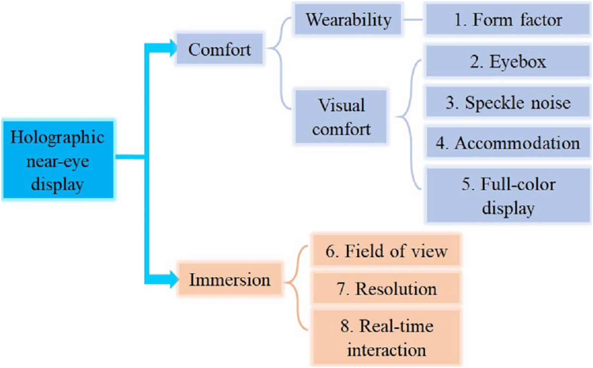
Categorization of holographic near-eye displays from the human-centric perspective.
2. HUMAN VISUAL SYSTEM
The human eye is an optical imaging system that has naturally evolved. Light rays enter the eye through an adjustable iris, which controls the light throughput. After being refracted by the cornea and crystalline lens, the light forms an image on the retina, where the photoreceptors convert the light signals to electrical signals. These electrical signals then go through significant signal processing on the retina (e.g., inhibition by the horizontal cells) prior to the brain. Finally, the brain interprets the images and perceives the object in 3D based on multiple cues.
With binocular vision, humans have a horizontal field of vision FOV of almost 200°, in which 120°[ISP]is a binocular overlap. Figure 2 shows the horizontal extent of the angular regions of the human binocular vision system [17]. The vertical field of vision is approximately 130°. Adaption for the eye’s natural field of vision is vital for an immersive experience. For example, there is a consensus that the minimal required FOVs for VR and AR displays are 100°[ISP]and 20°, respectively [18]. With the eye’s visual field, the photoreceptor density significantly varies between the central and peripheral areas [19]. The ability of the eye to resolve small features is referred to as visual acuity. The visual acuity is highly dependent on the photoreceptor density. The central area of the retina, known as the fovea, has the highest photoreceptor density, and this area spans a FOV of 5.2°. Outside the fovea, the visual acuity drops dramatically. The uniform distribution of photoreceptors is a result of natural evolution, accommodating the on/off-axis resolution of the eye lens. Therefore, to efficiently utilize the display pixels, a near-eye display must be optimized to provide a varying resolution that matches the visual acuity across the retina.
Fig. 2.

Visual fields of the human eye.
As a 3D vision system, the human eyes provide depth cues, which can be further categorized into physiological and psychological cues. Physiological depth cues include accommodation, convergence, and motion parallax. Vergence is known as the rotation of each eye in opposite directions so that the eyes’ lines of sight converge on the object, while accommodation is the ability of adjusting optical power of the eye lens so the eye can focus at different distances. For near-eye displays, it is crucial to present images at locations where the vergence distance is equal to the accommodation distance. Otherwise, the conflict between the two will induce eye fatigue and discomfort [20]. Psychological depth cues are enabled through our experience of the world, such as linear perspective, occlusion, shades, shadows, and texture gradient embedded in a 2D image [21].
Last, the human eye is constantly moving to help acquire, fixate, and track visual stimuli. To ensure the displayed image is always visible, the exit pupil of the display system—the eyebox—must be larger than the eye movement range, which is ~12 mm. For a display system, the product of the eyebox and FOV is proportional to the space-bandwidth product of the device, and it is finite. Therefore, increasing the eyebox will reduce the FOV and vice versa. Although the device’s space-bandwidth product can be improved through complicated optics, it often compromises the form factor. To alleviate this problem, common strategies include duplicating the exit pupil into an array [22–24] and employing eye-tracking devices [25].
The knowledge of the eye is crucial for human-centric optimization, providing the basis for the hardware design. To maximize the comfort and immersion experience, we must build the display that best accommodates the optical architecture of the human vision system.
3. HOLOGRAPHIC NEAR-EYE DISPLAYS: COMFORT
A. Wearability
The form factor of a device determines its wearability. An ideal near-eye display must be lightweight and compact like a regular eyeglass, allowing comfortable wearing for all-day use. Compared with other techniques, holographic near-eye displays have an advantage in enabling a small form factor because of its simple optics—the key components consist of only a coherent illumination source and an SLM. The SLM is essentially a pixelated display that can modulate the incident light’s amplitude or phase by superimposing a CGH onto the wavefront.
For AR near-eye displays, the device must integrate an optical combiner, and its form factor must be accounted for. Most early-stage holographic near-eye displays use a beam splitter as an optical combiner, which combines the reflected light from the SLM and the transmitted light from real-world objects [Fig. 3(a)]. The modulated light from the SLM can be guided directly to the eye pupil through free-space propagation [26] or pass through an additional 4 f system for hologram relay [Fig. 3(b)] [27] or frequency filtering [28,29]. Ooi et al. also embedded multiple beam splitters into an element for see-through realization with a large eyebox in an electro-holography glass [30].
Fig. 3.
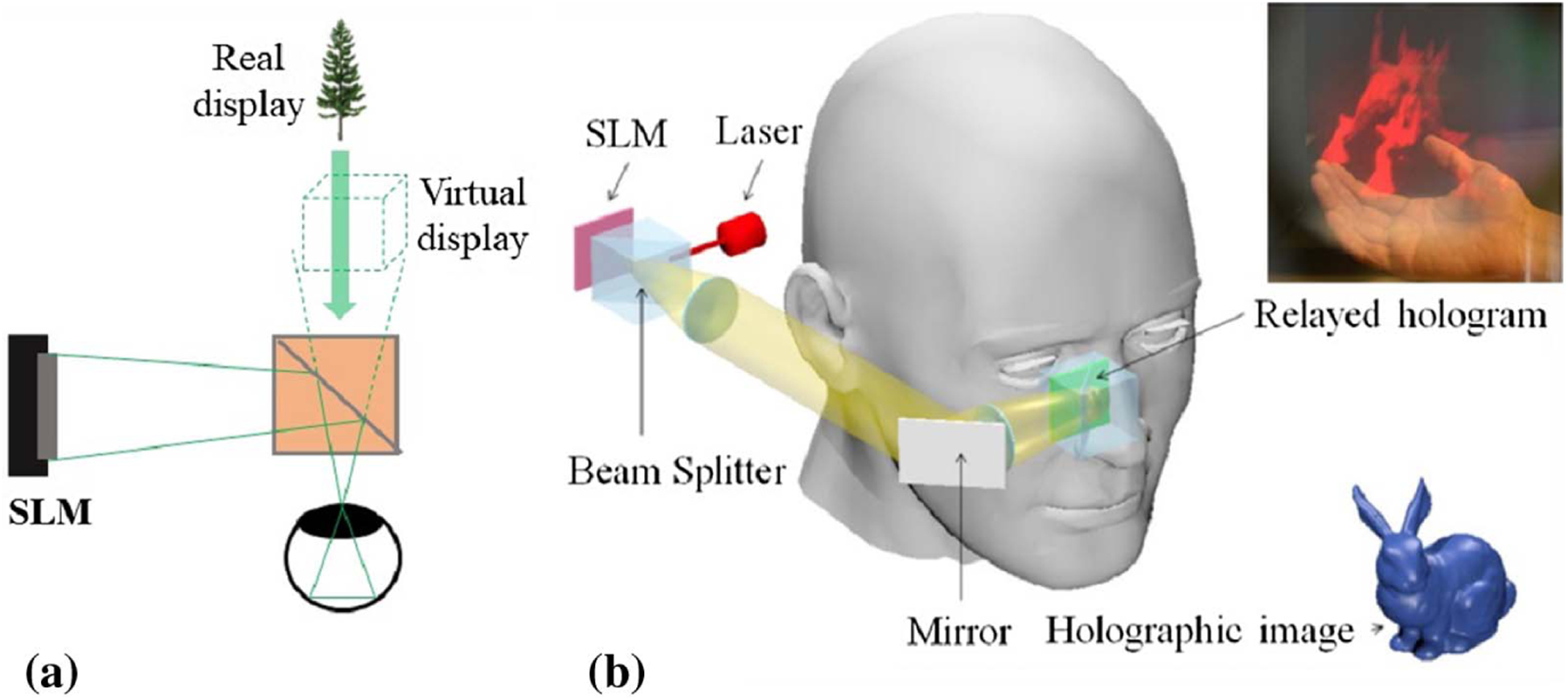
Holographic see-through near-eye display with a beam splitter as an optical combiner. (a) Conceptual schematic setup. (b) The hologram is relayed and reflected in the eye by a beam splitter through a 4 f system (reproduced with permission from [27], 2015, OSA).
Despite being widely used in proof-of-concept demos, the beam splitter is not an ideal choice regarding the form factor because of its cubic shape. As an alternative, the holographic optical element (HOE) is thin and flat, and it functions like a beam splitter. As a volume hologram, the HOE modulates only the Bragg-matched incident light while leaving the Bragg-mismatch light as is. When being implemented in a holographic near-eye display, the HOE redirects the Bragg-matched light from the SLM to the eye pupil and transmits the light from the real-world scene without adding additional optical power. Moreover, the ability to record diverse wavefront functions into the HOE allows it to replace many conventional optical components, such as lenses and gratings, further reducing the volume of the device.
The first implementation of the HOE in a near-eye display was performed by Ando et al. in 1999 [33]. In a holographic near-eye display, the HOE is usually deployed in an off-axis configuration [Fig. 4(a)], where the light from the SLM impinges on the HOE at an oblique incident angle. The HOE can be fabricated as a multi-functional device, integrating the functions of mirrors and lenses. For example, the HOE has been employed as an elliptically curved reflector [31,34] and a beam expander [35]. Curved/bent HOEs have also been reported to reduce the form factor and improve system performance in FOV and image quality [36]. To further flatten the optics and miniaturize the system, Martinez et al. used a combination of a HOE and a planar waveguide to replace the off-axis illumination module [37]. A typical setup is shown in Fig. 4(b), where the light is coupled into and out of the waveguide, both through HOEs [32,38,39]. Noteworthily, conventional HOEs are fabricated by two-beam interference [40]. Limited by the small refractive index modulation of the holographic materials induced in the recording process, conventional HOEs work for only monochromatic light with a narrow spectral and angular bandwidth. The recent advances in metasurface [41,42] and liquid crystals [43,44] provide alternative solutions. For example, Huang et al. demonstrated a multicolor and polarization-selective all-dielectric near-eye display system by using a metasurface structure as the CGH to demultiplex light of different wavelengths and polarizations [41,42].
Fig. 4.
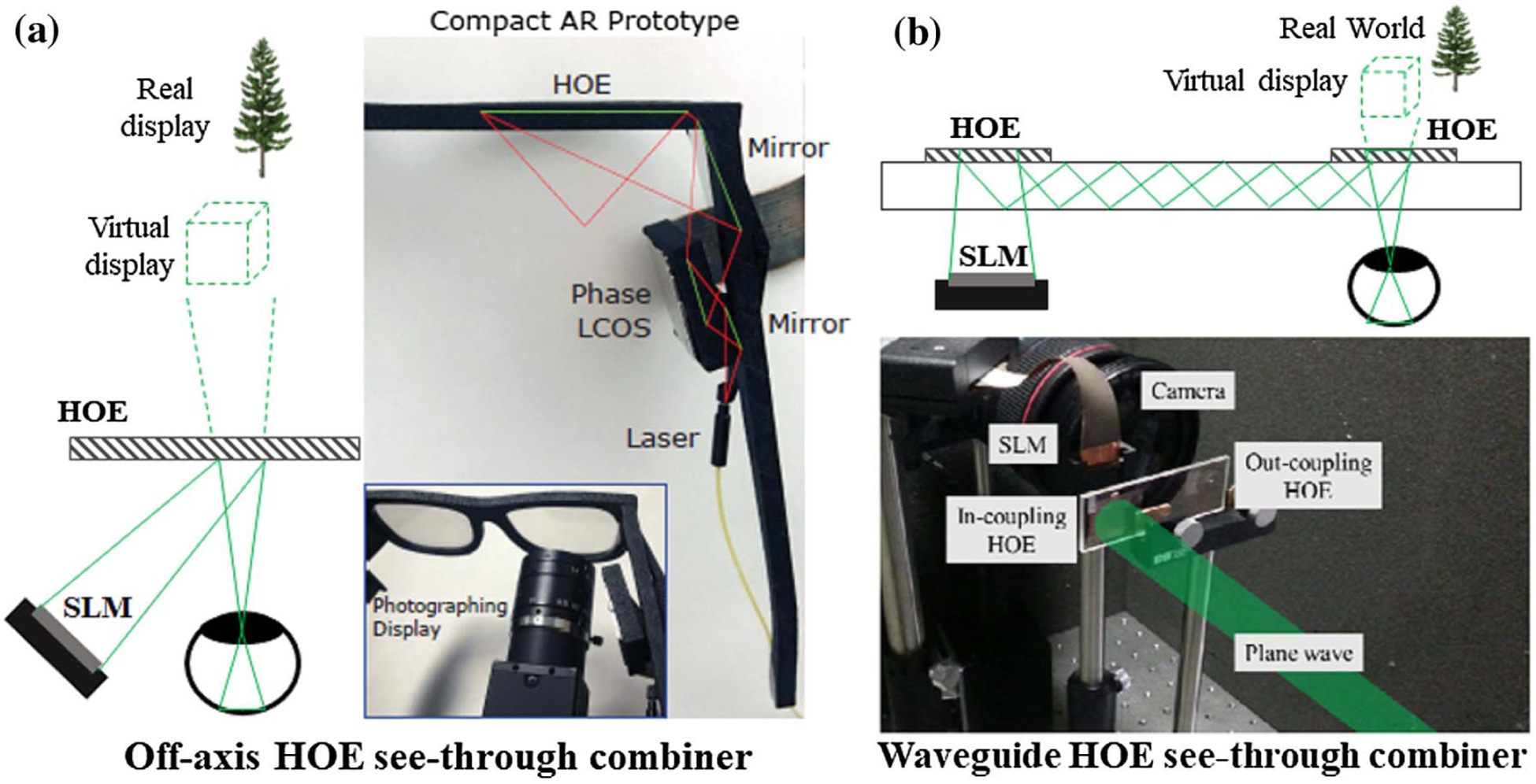
Holographic optical element (HOE) as an optical combiner. (a) Off-axis HOE geometry (included here by permission from [31], 2017, ACM). (b) Waveguide geometry (reproduced with permission from [32], 2015, OSA).
B. Visual Comfort
1. Eyebox
In lensless holographic near-eye displays, the active display area of the SLM determines the exit pupil of the system and thereby the eyebox. However, to add the eye relief, we must axially shift the exit pupil from the SLM plane. We can use a 4 f relay for this purpose [Fig. 5(a)] and magnify the pupil. In this configuration, the CGH can be computed directly using numerical diffraction propagation algorithms, such as a Fresnel integral method or an angular spectrum method [47]. However, the use of the optical relay increases the device’s form factor. Alternatively, we can rely on only the CGH to shift the exit pupil [Fig. 5(b)]. In this case, we can use a double-step diffraction algorithm to compute the CGH, where the desired eyebox location serves as an intermediate plane to relay the calculated hologram.
Fig. 5.
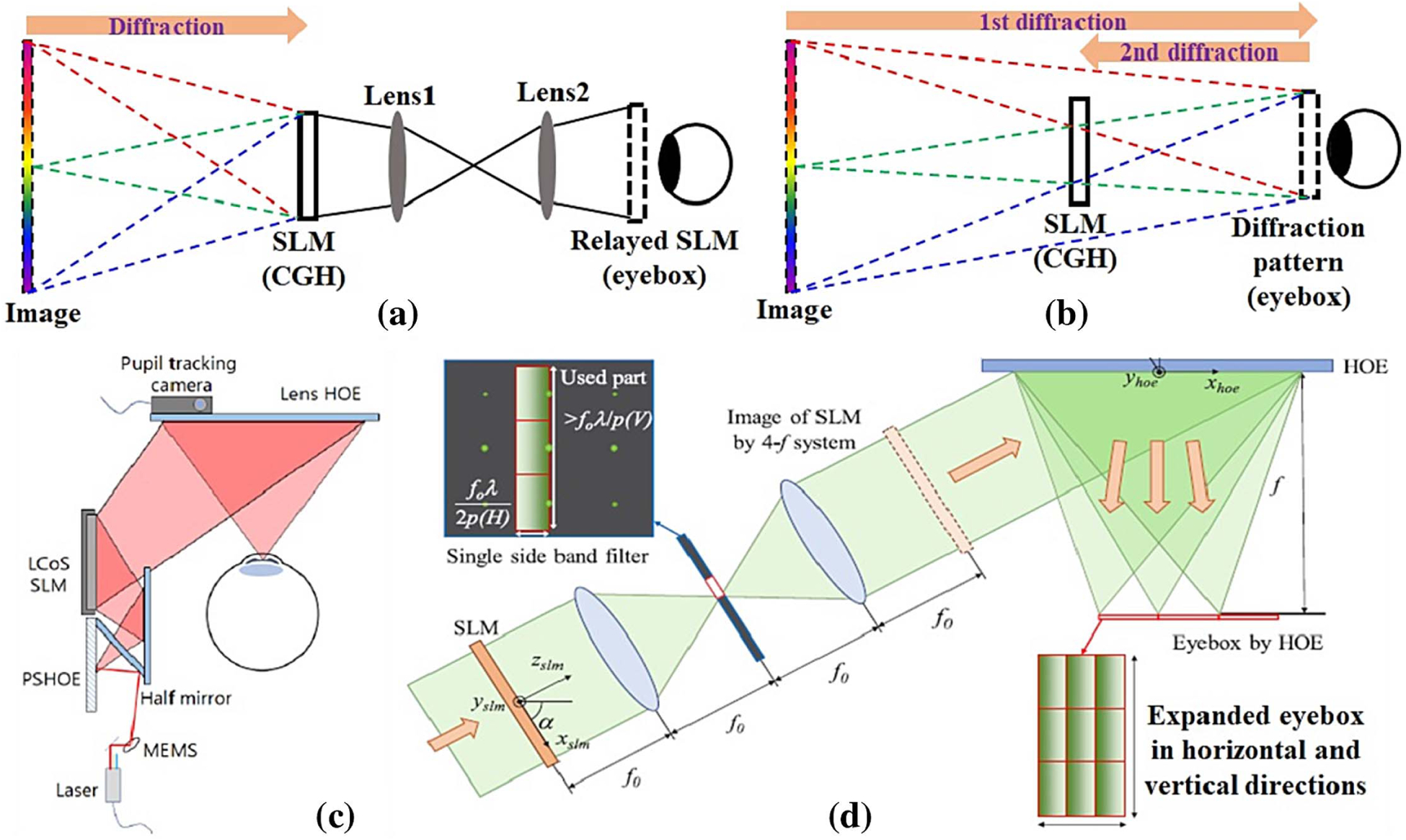
Eyebox relay through (a) 4 f system and (b) CGH. Eyebox expansion through (c) pupil tracking (included here by permission from [45], 2019, ACM) and replication (reproduced with permission from [46], 2020, OSA).
For a comfortable viewing experience, the near-eye display must provide an eyebox that is greater than the eye movement range. Active pupil tracking and passive pupil replication are two main strategies. A representative schematic of active pupil tracking is shown in Fig. 5(c). According to the detected eye position, a micro–electro–mechanical-system (MEMS) mirror changes the incident angle of light on the SLM, adding a linear phase to the diffracted wave. After being focused by another HOE, the wavefront converges at the exit pupil, which dynamically follows the eye’s movement [45]. While the active method requires additional components to track the eye pupil’s movement, the passive method directly replicates the exit pupil into an array, thereby effectively expanding the eyebox. Park and Kim [48] demonstrated the expansion of the eyebox along the horizontal axis by multiplexing three different converging beams on a photopolymer film. Later, they extended this work to the vertical axis by leveraging the high-order diffractions of the SLM [Fig. 5(d)] [46]. Jeong et al. developed another passive eyebox expansion method using a custom HOE fabricated by holographic printing [49]. The resultant method expands the eyebox along both horizontal and vertical axes while maintaining a large FOV (50°). The passive eyebox expansion method using holographic modulation has also been implemented in Maxwellian displays [50,51]. The conventional Maxwellian display optics uses refractive lenses to reduce the effective exit pupil into a pinhole, thereby rendering an all-in-focus image. In contrast, a holographic Maxwellian display replaces the refractive lenses with holograms, modulating the wavefront into an array of focused “pinholes” for eyebox expansion. The duplication of a pinhole-shaped pupil was accomplished by multiplexing concave mirrors into a single waveguide HOE [Fig. 6(a)] [50] or numerically encoding the hologram with multiple off-axis converging spherical waves [Fig. 6(b)] [51].
Fig. 6.
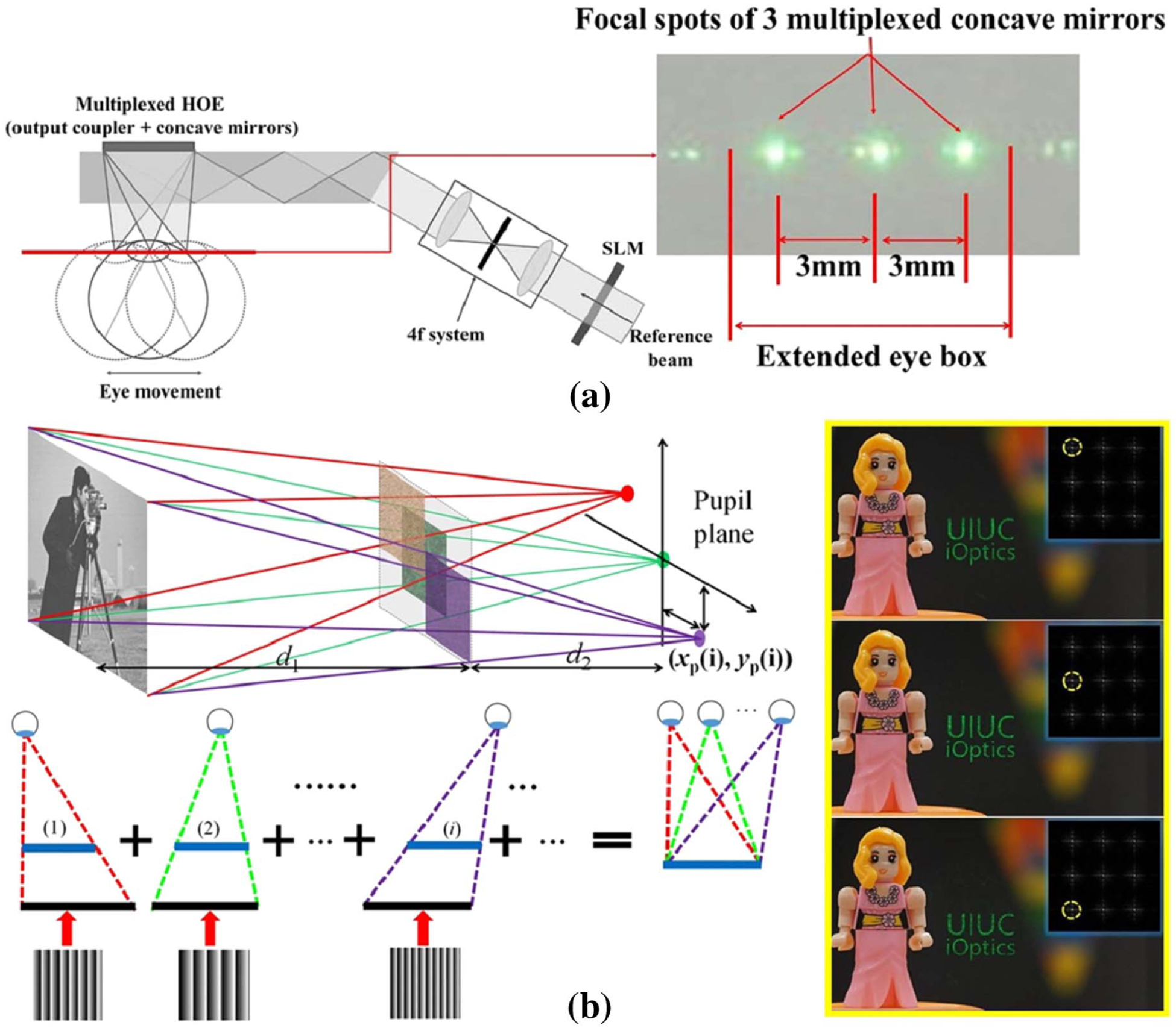
Eyebox expansion in a Maxwellian display using holographic modulation through (a) HOE (reproduced with permission from [50], 2018, OSA) and (b) encoding CGH with multiplexed off-axis plane waves (reproduced with permission from [51], 2019, Springer Nature).
2. Speckle Noise
Holographic displays commonly use lasers as the illumination source due to the coherence requirement. However, the use of lasers induces the speckle noise, a grainy intensity pattern superimposed on the image. To suppress the speckle noise, we can adopt three strategies: superposition, spatial coherence construction, and temporal coherence destruction.
In the superposition-based method, we first calculate a series of holograms for the same 3D object by adding statistically independent random phases to the complex amplitude, followed by sequentially displaying them on the SLM within the eye’s response time [Fig. 7(a)]. Due to the spatial randomness, the average contrast of the summed speckles in the reconstructed 3D image is reduced, leading to improved image quality [52]. This method has been used primarily in layer-based 3D models [27,53], where the calculation of the holograms is computationally efficient. Alternatively, we can use high-speed speckle averaging devices, such as a rotating or vibrating diffuser. Figure 7(b) shows an example of superposition by placing a rotating diffuser in front of the laser source. In this case, the speckle patterns are averaged within the SLM’s frame time at the expense of an increased form factor.
Fig. 7.

Speckle noise suppression by (a) superposition of multiple CGHs [53], (b) rotating diffuser, and (c) complex amplitude modulation using a single CGH (reproduced with permission from [29], 2017, OSA).
The speckle noise is caused by the destructive spatial interference among the overlapped imaged point spread function [54]. We can alleviate this problem by actively manipulating spatial coherence constructions. Within this category, the most important method is complex amplitude modulation, which introduces constructive interference to the hologram. Rather than imposing random phases on the wavefront, complex amplitude modulation uses a “smooth” phase map, such as a uniform phase, for constructive interference among overlapped imaged spots. To synthesize a desired complex amplitude field using the phase-only or amplitude-only CGH, we can use analytic multiplexing [55,56], double-phase decomposition [57,58], double-amplitude decomposition [26,29], optimization-enabled phase retrieval [59–61], or neural holography [62]. Figure 7(c) shows an example where the complex amplitude wavefront is analytically decomposed into two-phase holograms and loaded into different zones of an SLM. The system then uses a holographic grating filter to combine the holograms and reconstruct complex amplitude 3D images [29]. The major drawback of this method is the requirement that the complex wavefront contains only low frequencies, resulting in a small numerical aperture at the object side. This increases the depth of field and thereby weakens the focus cue. As an alternative solution, Makowski et al. introduced a spatial separation between the adjacent image pixels to avoid overlaps in the image space, thereby eliminating spurious interferences [54].
Last, using a light source with low temporal coherence can also suppress the speckle noise. Partially coherent light sources, such as a superluminescent light-emitting diode (sLED) and micro LED (mLED), are usually employed for this purpose [63]. Also, a spatial filter can be applied to an incoherent light source to shape its spatial coherence while leaving it temporally incoherent. As an example, the spatially filtered LED light source has been demonstrated in holographic displays to reduce the speckle noise [64,65]. Recently, Olwal et al. extended this method to an LED array and demonstrated high-quality 3D holography [66]. The drawbacks of using a partially coherent light source include reduced image sharpness and a shortened depth range. However, the latter can be compensated for by reconstructing the holographic image at a small distance near the SLM, followed by using either a tunable lens [67] or an eyepiece [68] to extend the depth range.
3. Accommodation
The accommodation cue in holographic displays can be accurately addressed by computing the CGH based on physical optical propagation and interference. In physically based CGH calculation, the virtual 3D object is digitally represented by a wavefront from point emitters [31,69] or polygonal tiles [70]. These two models usually require a dense point-cloud or mesh samplings to reproduce a continuous and smooth depth cue. Although there are many methods to accelerate the CGH calculation from the point-cloud or polygon-based 3D models, such physically based CGHs face challenges in processing the enormous data in real time. Moreover, occlusion is often not easily implemented in physically based CGHs, limiting virtual 3D objects to simple geometries.
The advance of computer graphics has led to two image-rendering models that can help a holographic display produce the accommodation cue more efficiently: the layer-based model and the stereogram-based model. The layer-based model renders a 3D object as multiple depth layers, followed by propagating the layer-associated wavefronts to the hologram through fast-Fourier-transform (FFT)-based diffraction [71–73]. To render a continuous 3D object with finite depth layers, Akeley et al. developed a depth-weighted blending (or depth-fused) algorithm [74,75]. This algorithm makes the image intensity at each depth plane proportional to the dioptric distance of the point from that plane to the viewer along a line of sight (Fig. 8) using a linear [76] or nonlinear [77] model. Other rendering methods include using an optimization algorithm to compute the layer contents that best match the imaged scene at the retina when the eye focuses at different distances [78], or using color to binary decomposition of a 3D scene into multiple binary images for digital micromirror device (DMD)-based display [79]. As an alternative solution to create continuous depth views by multiplane images, we can also consider displaying high density stacks of depth/focal planes from CGHs using high-speed focus-tunable optics [80,81].
Fig. 8.
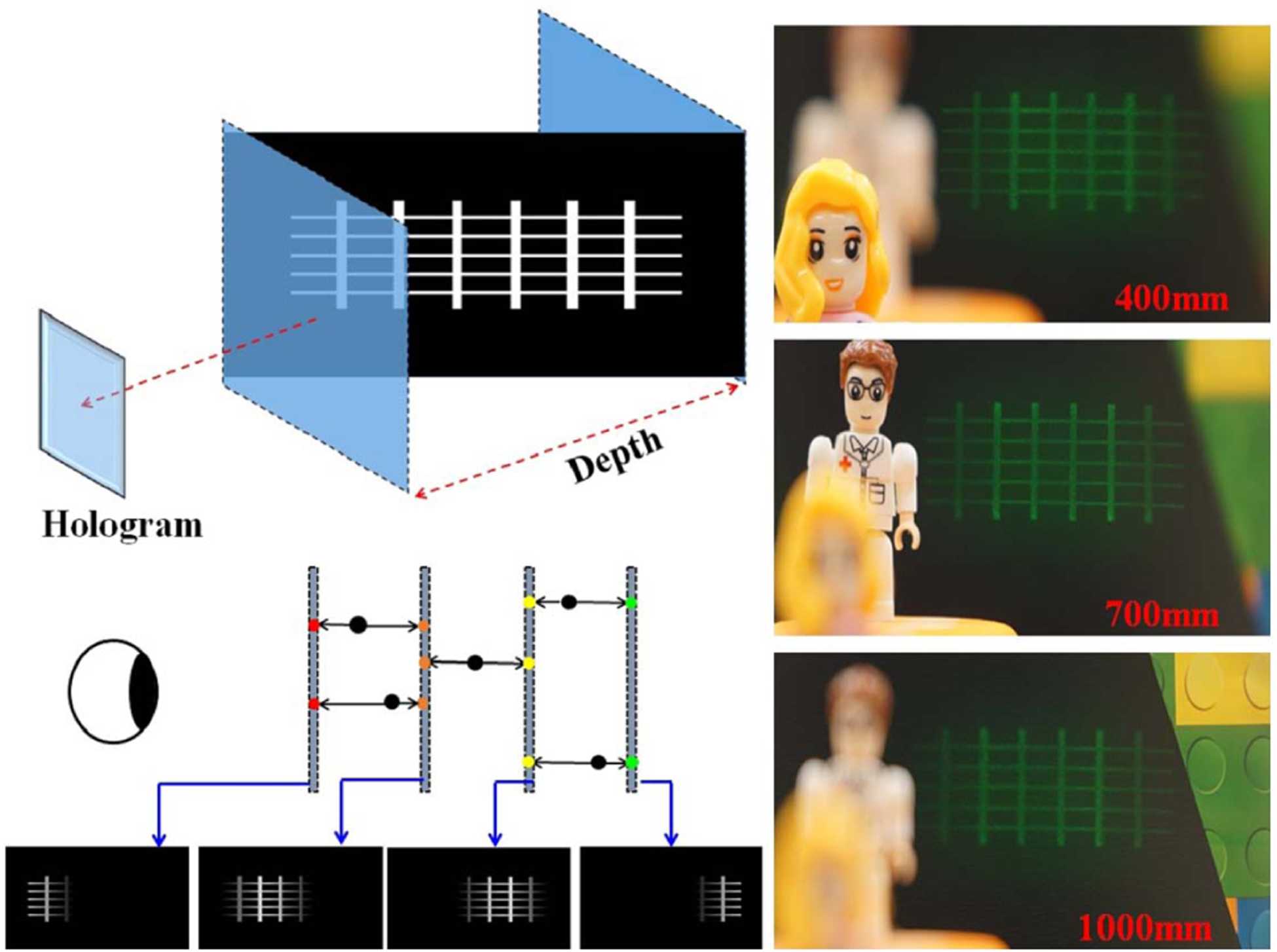
Holographic multiplane near-eye display based on linear depth blending rendering [53].
Despite being computationally efficient, the layer-based model has difficulties in rendering the view-dependent visual effects, such as occlusions, shading, reflectance, refraction, and transparency. In contrast, the holographic stereogram model can provide both the accommodation cue and view-dependent visual effects. As illustrated in Fig. 9(a), this model first calculates the light field of a 3D object using a ray-based propagation method. Then it computes the CGH by converting the light field into a complex wavefront [82]. Simply put, the CGH is spatially partitioned into small holographic elements, referred to as “hogel,” that direct light rays (plane waves) to varied directions to form the correspondent view images. Like the light field display, the holographic stereogram requires a choice of hogel size, imposing a hard tradeoff between spatial and angular resolutions. Noteworthily, this tradeoff has been recently mitigated by using two non-hogel-based methods. The first method is to encode a compressed light field into the hologram [83]. The second method uses an overlap-added stereogram (OLAS) algorithm to convert the dense light field data into a hologram [Fig. 9(a)] [84,85], enabling more efficient computation and improving image quality.
Fig. 9.
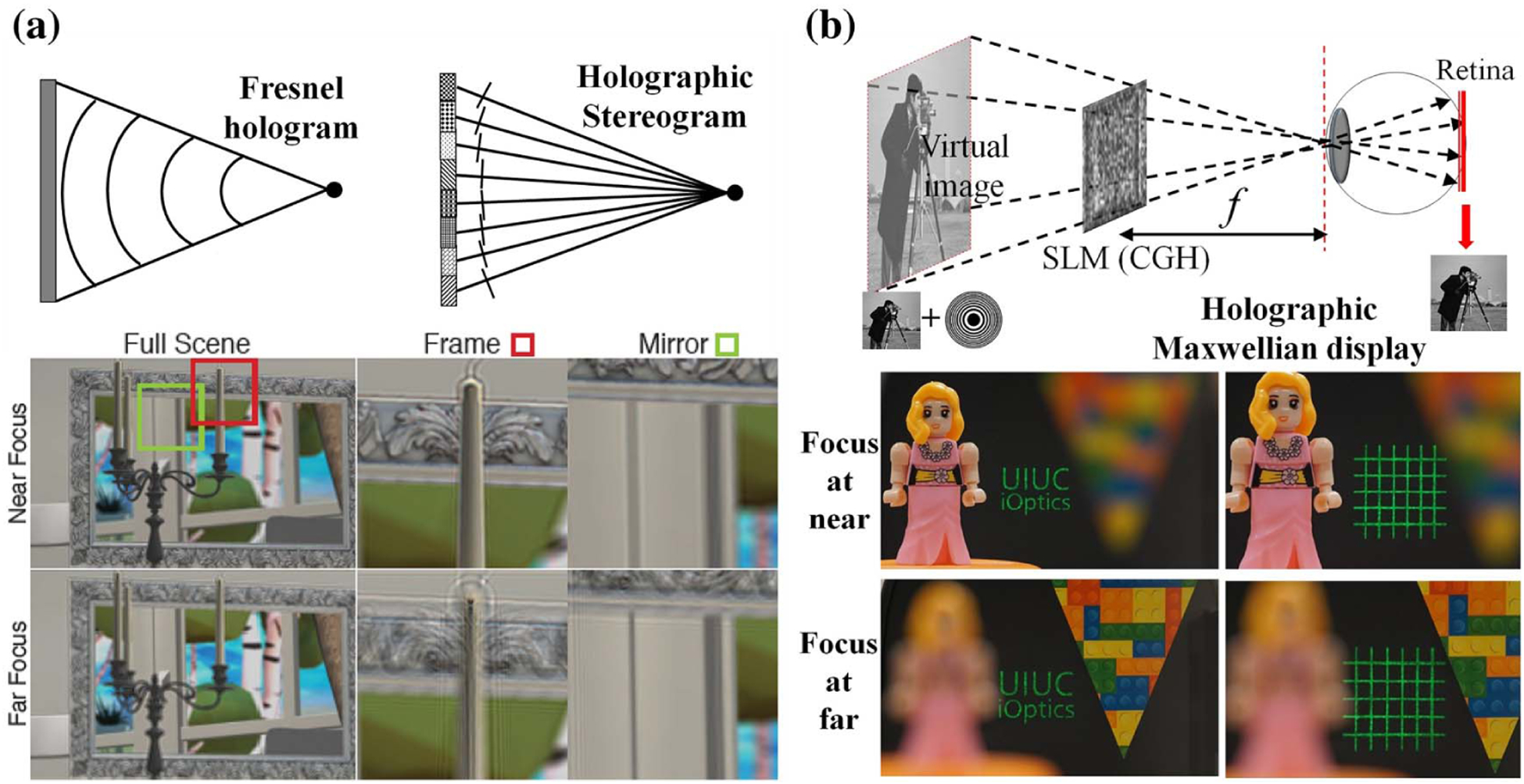
Holographic stereogram and Maxwellian view. (a) Holographic stereogram for realistic 3D perception (included here by permission from [85], 2019, ACM). (b) Holographic Maxwellian view (reproduced with permission from [51], 2019, Springer Nature).
The Maxwellian display is another strategy to mitigate the VAC by completely removing the accommodation cues [87,88]. Because the display needs to render only an all-in-focus image, the computational cost is minimized. In a holographic Maxwellian near-eye display, the complex hologram is a superimposed pattern of a real target image and a spherical phase. The light emitted from this hologram enters the eye pupil and forms an all-in-focus image on the retina, as depicted in Fig. 9(b) [51,89]. The flexible phase modulation of the CGH allows correcting wavefront errors in the pupil to produce Maxwellian retinal images for astigmatic eyes [89]. Lee et al. also developed a multi-functional system where they can switch between the holographic 3D view and the Maxwellian view using a switchable HOE [90] or simultaneously display both using temporal multiplexing [91]. Later, they further improved this method by using a foveated image rendering technique [92].
4. Full-Color Display
Displaying colors is challenging for holographic near-eye displays because the CGH is sensitive to the wavelength. There are two methods for full-color reproduction: temporal [86,93] and spatial division [94,95]. Temporal division calculates three sub-CGHs for the RGB components of a 3D object, followed by displaying them sequentially on a single SLM. Accordingly, an RGB laser source illuminates the sub-CGH at the corresponding wavelength [28,31,93]. Figure 10(a) shows a typical setup where each sub-CGH is sequentially illuminated from the RGB laser source. The double-phase encoding and frequency grating filtering are employed for complex amplitude modulation in each color channel [86]. In contrast, spatial division simultaneously displays three CGHs for RGB colors on three SLMs [94] or different zones of a single SLM [95], which are illuminated by the lasers of the corresponding wavelengths. The reconstructed RGB holographic images are then optically combined and projected onto the retina. However, due to the use of multiple SLMs and lasers, the resultant systems generally suffer from a significant form factor. To address this problem, Yang et al. developed a compact color rainbow holographic display [96], where they display only a single encoded hologram on the SLM under white LED illumination. A slit spatial filter is then used in the frequency domain to extract the RGB colors.
Fig. 10.
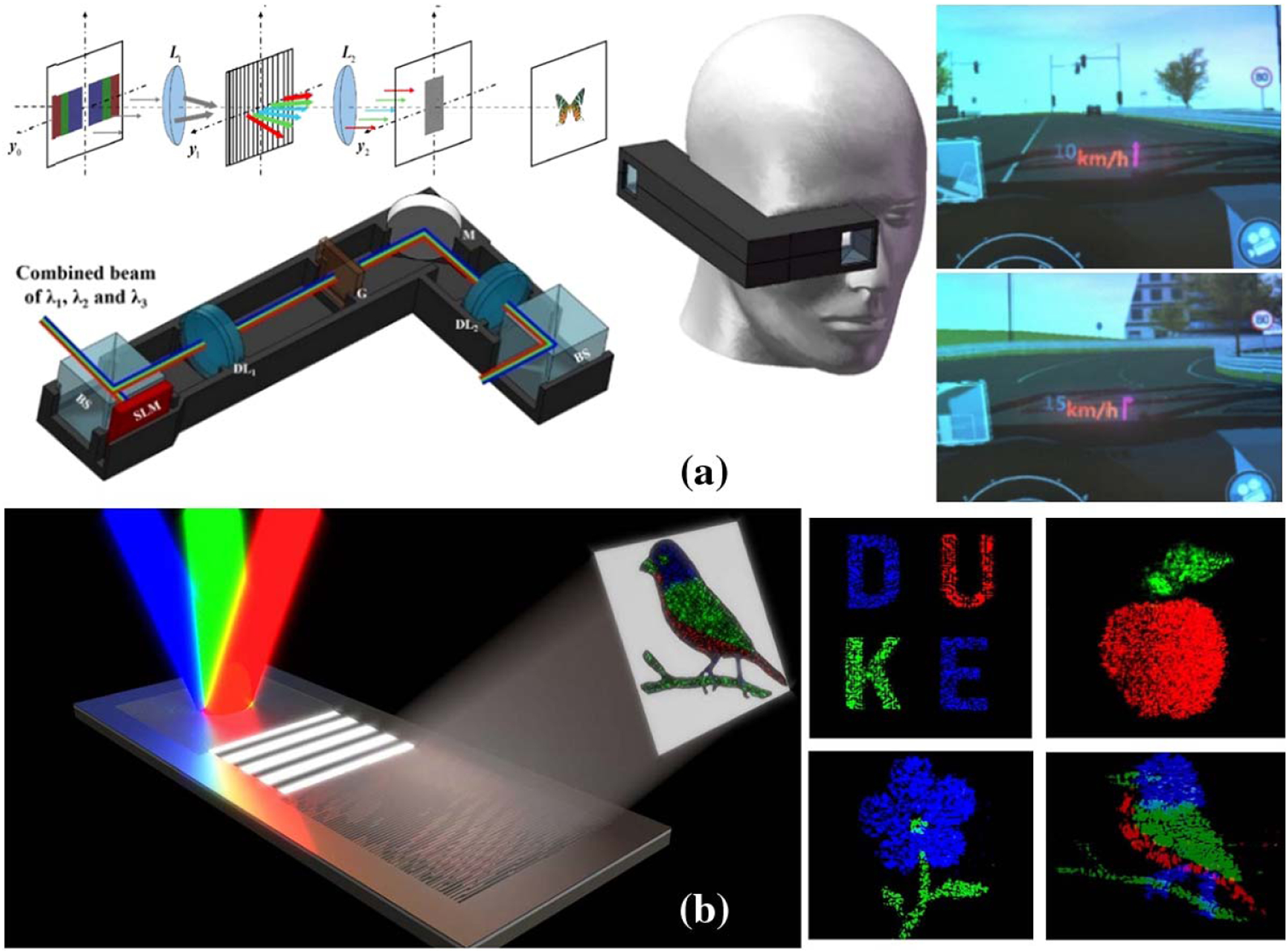
Color holographic near-eye display using (a) time division (reproduced with permission from [86], 2019, OSA) and (b) metasurface HOE (reproduced with permission from [41], 2019, OSA).
For AR applications, several full-color waveguide HOEs have been developed to combine virtual and real-world images. To enable the transmission of multiple wavelengths, we can fabricate a multilayer structure in the HOE recording, each layer responding to a different color [97]. Alternatively, a metasurface component can also be used for color mixing [41]. An example is shown in Fig. 10(b). The RGB illumination light is coupled into the waveguide through a single-period grating at different incident angles. After being transmitted to the eye side and coupled out through a binary metasurface CGH, the light recombines and forms a multicolor holographic image in the far field.
4. HOLOGRAPHIC NEAR-EYE DISPLAYS: IMMERSION
A. Field of View
The FOV is defined as an angular or distance range over which the object spans. In holographic displays, the SLM (loaded with a Fresnel or Fourier hologram) generally locates at the exit pupil of the display system, so the diffraction angle θmax of the SLM determines the maximum size of the holographic image and, therefore, the system’s FOV. Given the SLM pixel size p and the cone angle of the incident beam θin, the maximum diffraction angle can be calculated as [98]
| (1) |
If we consider plane-wave illumination, we can simplify Eq. (1) as θmax = sin−1 (λ/2p). To create an eye relief for comfortable wearing, a typical near-eye display usually uses an eyepiece to relay the wavefront on the SLM to the eye pupil, as shown in Fig. 11(a). Given a distance, dslm, between the SLM and the eyepiece, the eye relief, deye, can be calculated as deye = |1/(1/f − 1/dslm)|, where f is the focal length of the eyepiece. The FOV can then be calculated as the diffraction angle of the relayed SLM through the eyepiece:
| (2) |
where M = deye/dslm is the magnification of the eyepiece.
Fig. 11.
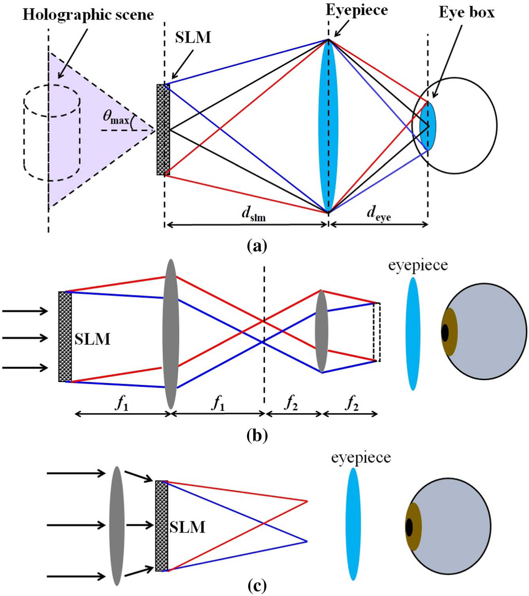
FOV in a holographic near-eye display. (a) Holographic near-eye display involving an eyepiece. (b) Enlarging the FOV through pupil relay. (c) Enlarging the FOV through spherical-wave illumination.
The typical pixel size of an SLM varies from 3 μm to 12 μm. Therefore, the diffraction angle θmax is generally less than 5° under plane-wave illumination. To expand the FOV, we can use two strategies to increase the diffraction angle for a given SLM: pupil relay and spherical-wave illumination [68]. The first strategy uses a 4 f relay system to de-magnify the SLM [Fig. 11(b)]. The imaged pixel size becomes smaller, leading to a larger diffraction angle θmax according to Eq. (1) and, therefore, a larger FOV. The second strategy uses a spherical wavefront to illuminate the SLM [Fig. 11(c)] [99], increasing the diffraction angle and thereby the FOV. In another implementation, Su et al. used an off-axis holographic lens to replace spherical-wave illumination, introducing the quadratic wavefront modulation after the SLM [100].
Despite being simple to implement, both strategies above sacrifice the eyebox size because of a finite space-bandwidth product. To alleviate this tradeoff, we can use multiple SLMs in a planar or curved configuration [101–107]. However, this method cannot be readily applied to the near-eye display because of a large form factor. A more practical approach is to use SLM with reduced pixel size, thereby allowing more pixels to be packed in the same area. Further reducing the pixel size of current liquid crystal on silicon (LCoS)- or DMD-based SLMs is challenging due to the manufacturing constraint [108–110]. In contrast, the dielectric metasurface holds great promise in this aspect—it can encode CGHs with a pixel size at the subwavelength scale (~300 nm), therefore enabling a much larger FOV (~60 deg) than the current systems. Moreover, the metasurface hologram can control the polarization state of light at the pixel level [111], allowing more degrees of freedom for increasing the space-bandwidth product. As a novel technique, the dielectric metasurface holography still faces many challenges, such as a lack of algorithms for nanoscale and vectorial diffraction, a high-cost and time-consuming fabrication process, and inability to dynamically modulate the wavefront.
As an alternative solution, temporal multiplexing can be employed to increase the FOV at the expense of a reduced frame rate. Figure 12(a) illustrates a representative system using a temporal division and spatial tiling (TDST) technique [98]. Two CGHs with spatially separated diffractions are displayed on the SLM sequentially. The output images are then tiled on a curved surface, increasing the horizontal FOV by a factor of four. A similar method that uses resonant scanners has also been reported [112,113]. Figure 12(b) shows another temporal-multiplexing setup that utilizes the high-order diffraction of an SLM [114]. Li et al. tiled different diffraction orders of the SLM in the horizontal direction and passed a specific order at a time through a synchronized electro-shutter. Three-times improvement in horizontal FOV has been demonstrated.
Fig. 12.

Enlarging the FOV through (a) temporal division and spatial tiling (reproduced with permission from [98], 2013, OSA) and (b) temporal division and diffraction-order tiling [114].
B. Resolution and Foveated Rendering
Most current commercial near-eye displays provide an angular resolution of 10–15 pixels per degree (ppd), whereas the acuity of a normal adult is about 60 ppd. The pixelated image jeopardizes the immersive experience. The foveated display technique has been exploited to improve the resolution in the central vision (~± 5°) while rendering the peripheral areas with fewer pixels. When combined with eye tracking, the foveated display can provide a large FOV with an increased perceived resolution. The common implementation is to use multiple display panels to create images of varied resolutions [115,116]. The foveal and peripheral display regions can be dynamically driven by gaze tracking using the traveling micro-display and HOE [117].
In holographic near-eye displays, foveated image rendering has been used primarily to reduce the computational load [118–123]. Figures 13(a) and 13(b) illustrate examples of using foveated rendering for generating CGHs for the point-cloud-[118–120], polygon- (mesh) [121], and multiplane-based models [123]. All these implementations render a high-resolution image only for the fovea, while reducing resolution in peripheral areas, thereby significantly reducing the computation time for the CGH. To render a foveal image that follows the eye’s gaze angle, we must update the CGH accordingly. Figures 13(c) and 13(d) show the difference in image resolution when the eye gazes at different locations for the polygon- [121] and multiplane-based [123] models, respectively.
Fig. 13.
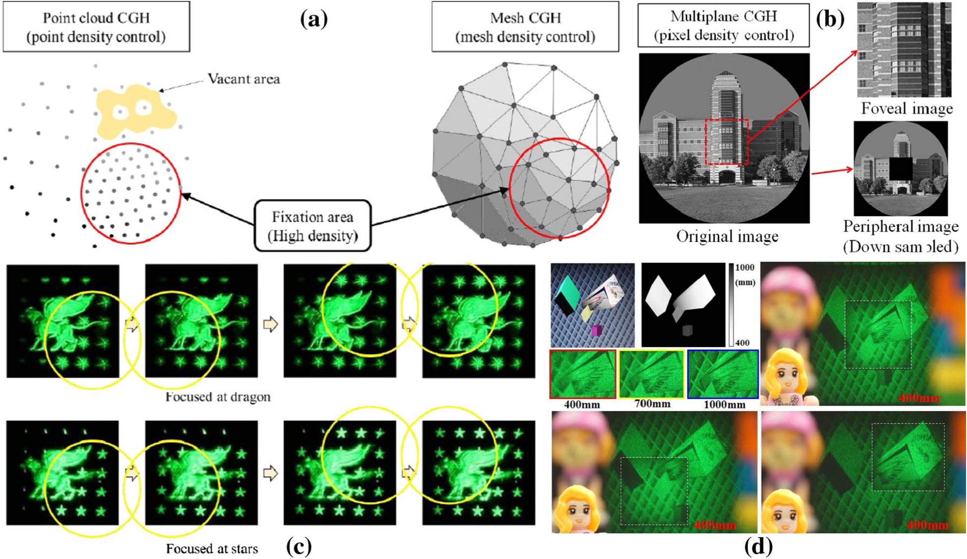
Foveated image rendering of (a) point-cloud and polygon-based models (reproduced with permission from [121], 2019, OSA) and (b) multiplane-based model [123]. The foveal content changes according to the eye gaze angle in (c) polygon-based model (reproduced with permission from [121], 2019, OSA) and (d) multiplane-based model [123].
C. Real-Time Interaction
1. Gesture and Haptic Interaction
Human–computer interaction is indispensable for enhancing the immersion experience. Gesture or haptic feedback has been applied widely in VR systems when a user experiences virtual objects in the displayed environment, providing a more realistic sensation to mimic the physical interaction process [124]. While haptic techniques rely on wearable devices such as haptic gloves, the gesture is more interactive to handle the virtual object in real time through hand and finger movements, which can be detected by a motion sensor. A state-of-the-art interactive bench-top holographic display was reported by Yamada et al. [125]. They used the CGH to display a holographic 3D image while employing a motion sensor (Leap Motion Inc.) to detect hand and finger gestures with high accuracy. However, the real-time CGH display with gesture interaction has yet to be explored in holographic near-eye displays.
2. Real-Time CGH Calculation
For current holographic near-eye displays, CGHs are usually calculated offline due to the enormous 3D data involved. For real-time interaction, fast CGH calculation is critical, which can be achieved through fast algorithms and hardware improvement.
To calculate the CGH, we commonly use algorithms based on the point-cloud-, polygon-, ray-, and multiplane-based models. In the point-cloud model, the 3D object is rendered as a large number of point sources. The calculation of the correspondent CGH can be accelerated using the lookup table (LUT) [126–128] and wavefront recording plane (WRP) methods [129]. Yet, it still requires significant storage and a high data transfer rate. The polygon-based model depicts the 3D object as aggregates of small planar polygons [70]. It is faster than the point-cloud by lowering the sampling rate and using FFT operation [130,131]. However, the reconstructed image suffers from fringe artifacts [132]. The ray-based model is faster than the point-cloud and polygon in CGH calculation [133,134]. Nonetheless, the capture or rendering of the light field incurs additional computational cost. So far, the multiplane model has been considered the best option for real-time interactive holographic near-eye displays because it involves only finite FFT operations between the planes and thereby offers the fastest CGH calculation speed [27]. Noteworthily, a recent study showed that exploring machine learning can further boost CGH calculation for the multiplane model, enabling real-time generation of full-color holographic images at a 1080p resolution [62].
On the other hand, advances in hardware, such as the deployment of field-programmable gate arrays (FPGAs) and graphic process units (GPUs), can increase the CGH calculation speed as well [135]. Recently, a powerful FPGA-based computer named “HORN” was developed for fast CGH calculation [136–138]. The HORN can execute CGH algorithms several thousand times faster than personal computers. For example, it can calculate the hologram of 1024 × 1024 pixels resolution from 1024 rendered multiplane images in just 0.77 s [139]. The practical use of FPGA-based approaches is hampered by the long R&D cycle of FPGA board design. Alternatively, GPUs can be used for the same purpose. For instance, NVIDIA Geforce series GPUs can calculate a CGH of 6400 × 3072 pixels from a 3D object consisting of 2048 points in 55 ms [140]. As another example, using the layer-based CGH algorithm, Gilles et al. demonstrated real-time (24 fps) calculation of CGH of 3840 × 2160 pixels [141]. We expect the high-performance GPU will be the enabling tool for real-time interactive holographic displays. Although we herein discuss only offline computing, real-time inline processing can be made possible by synergistic integration of novel algorithms and hardware.
5. OUTLOOK
We envision that the next-generation holographic near-eye displays will be as compact as regular eyeglasses, meeting the computing needs for all-day use. The ability to create a comfortable and immersive viewing experience is the key. As a rule of thumb, we must adapt the hardware design for the human vision system at both low and high levels. Low-level vision refers to a psychophysical process in which the eye acquires visual stimuli, and it involves both the physical optics of the eye and anatomical structure of the retina. In contrast, high-level vision refers to a psychometric process in which the brain interprets the image. It describes the signal processing in the visual cortex, such as perception, pattern recognition, and feature extraction. Figure 14 shows a hierarchical structure of signal processing of the human visual system.
Fig. 14.

Signal processing of the human visual system.
A. Adaption to Low-Level Vision
To adapt to low-level vision, we must match the FOV, resolution, and exit pupil of the display system with eye optics. For holographic near-eye displays, the major challenge lies in the tradeoff between the FOV and exit pupil (eyebox)—the product of these two factors is limited by the total number of pixels of the SLM. Based on the analysis in Section 4.A, under plane-wave illumination (θin = 0) and paraxial approximation (sin−1x ≈ x), the product of the FOV and eyebox along one dimension can be derived as
| (3) |
where N is the pixel numbers of the SLM in one dimension. Figure 15 shows the relationship between the FOV and eyebox when using an SLM of varied pixels according to Eq. (3) (λ=532 nm). In general, the larger the format of the SLM, the better the balance we can reach between the FOV and the eyebox. Conventional holographic displays are based on phase-only SLMs. However, the manufacturing cost of large-format phase-only SLMs is high, restricting their practical use in consumer products. In contrast, the amplitude-only SLM, such as an LCD or a DMD, is much more cost efficient. Also, recent studies demonstrated that a complex wavefront could be effectively encoded into an amplitude-only CGH, allowing it to be displayed on an amplitude-only SLM [53,123,142]. Therefore, we envision that amplitude-only large-format SLMs will be mainstream devices in future holographic near-eye displays. For example, with a state-of-the-art 8 K DMD [143,144], we can potentially achieve an 85° horizontal FOV with a 3 mm × 3 mm eyebox. An alternative direction is to exploit superresolution by mounting masks with fine structures on a regular SLM, thereby increasing the diffraction angle without compromising the total diffraction area. For example, the use of a diffusive medium [145], a random phase mask [146,147], and a non-periodic photon sieve [148] have been reported for this purpose. However, using these additional masks complicates image reconstruction and degrades image quality. To solve this problem, we can explore the machine-learning-based method, which has been demonstrated effective in complex-media-based coherent imaging systems [149,150].
Fig. 15.
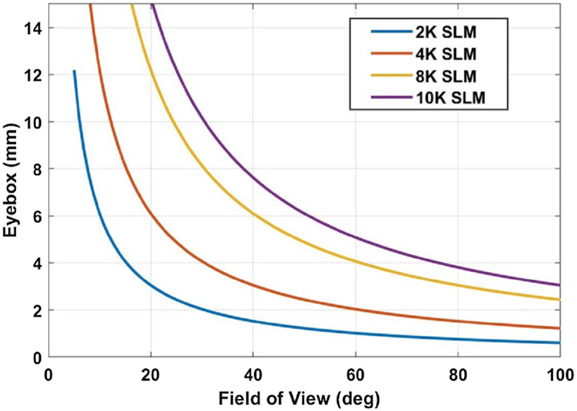
Tradeoff relations between FOV and eyebox (wavelength is 532 nm in the calculation).
The resolution provided by a holographic display is determined by the modulation transfer function (MTF) of the eye at a specific pupil size (i.e., the smaller of the exit pupil of the display and eye pupil). Adapting to the eye’s native resolution, therefore, means rendering an image with a varied resolution that matches with the radial MTF of the eye. The foveated technique has been demonstrated highly effective in this regard, significantly reducing the computational cost and thereby holding promise to enable real-time human–computer interaction. Noteworthily, as demonstrated in a recent work [151], the efficiency and quality of foveated rendering can be further improved by the deep-learning-based method. In addition, a study shows that the human eye possesses a lower resolution in response to the blue color compared to red and green [152,153]. The future holographic near-eye displays can take this fact into consideration when rendering different resolutions for the RGB channels.
For visually impaired eyes such as myopia and hyperopia, adapting to the eye’s native resolution also means correcting for the defocus/astigmatism of the eye lens. Currently, most holographic near-eye displays do not provide this function, and users with visual impairment must wear extra prescription glasses. Holographic near-eye displays have a unique advantage in correcting for eye aberrations by simply adding a compensating phase map to the hologram, and this direction is yet to be explored.
B. Adaption to High-Level Vision
Adaption to high-level vision requires a thorough understanding of human perception, particularly regarding the way signals are processed in the visual cortex. Despite being equally important, there is a lack of awareness of the role that high-level vision plays in visual perception. An interesting fact is that a “perfect” image from the perspective of low-level vision may not be a “perfect” image from the perspective of high-level vision. For example, M. Banks’ group reported that the chromatic aberration induced by eye optics improves the realism perceived by the brain [154]. The same group also revealed that the blurred point spread function caused by the aberrated crystalline lens, which is considered a downside of low-level vision, actually helps the brain interpret the image to form 3D perception [155]. As another example, Wetzstein’s group recently showed that the rendering of ocular parallax—a small depth-dependent image shift on our retina—improves perceptual realism in VR displays [156]. To reflect this principle in holographic near-eye displays, we must optimize the hardware for “perceptual realism” rather than “photorealism.” For instance, to create perfect visual stimuli from the perspective of high-level vision, we must reproduce the “desired” aberrations in the reconstructed image when calculating the CGH (Fig. 16). Despite being studied extensively, there are still many unknowns regarding human perception. Further investigation of this area, therefore, requires synergistic efforts from both optical engineers and neuroscientists.
Fig. 16.
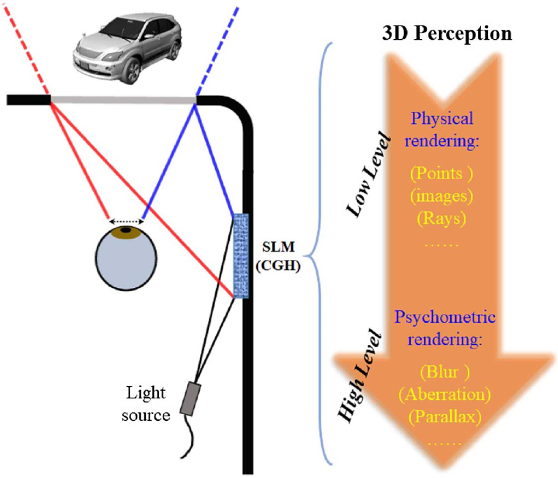
Reproduction of “perceptual realism” in holographic near-eye displays.
C. Challenges and Perspectives
Despite decades of engineering effort, the challenge of developing real-time, high-quality, and true (i.e., pixel-precise) 3D holographic displays remains. This challenge is caused by two problems: first, the limited space-bandwidth product offered by current SLMs and, second, the lack of fast algorithms that can generate high-quality holograms from 3D point-clouds, meshes, or light fields in real time.
The limited space-bandwidth product imposes a fundamental tradeoff between FOV or image size and eyebox or viewing zone size in near-eye and direct-view displays. Current 1080p or 4 k SLM resolutions are ready for near-eye display applications, but they are far from being able to support direct-view displays. For the latter application, large-scale panels with sub-micrometer-sized phase-modulating pixels or coherent emitter arrays are required, which is out of reach for today’s opto-electronic devices. However, progress has been made with solid-state LiDAR systems for autonomous driving. These LiDAR systems are optimized for beam steering applications, but similar to holographic displays, they require an array of coherent sources. Thus, we hope that efforts on continuing to push the resolution and size of coherent arrays, for example, via advances in laser or photonic waveguide technology, will eventually translate into display applications.
Improving CGH algorithms has been a goal of much recent work. Yet, achieving high-quality true 3D holographic image synthesis at real-time framerates has been a challenging and unsolved problem for decades. While conventional display technologies, such as liquid crystal or organic LED displays, can directly show a target image by setting their pixels’ states to match those of the image, holographic displays cannot. Holographic displays must generate a visible image indirectly through interference patterns of a reference wave at some distance in front of the SLM—and when using a phase-only SLM, there is yet another layer of indirection added to the computation. This challenge requires ultra-precise and automatic calibration of holographic displays. Moreover, to the best of our knowledge, no existing algorithm has been demonstrated to generate, transmit, and convert 3D image data into a hologram offering true 3D display capabilities. One of the most promising approaches to solve these long-standing challenges is to combine methodology developed for modern approaches to artificial intelligence (AI) with the physical optics of holography [62]. AI-driven CGH techniques show promise in solving many of these long-standing challenges.
6. CONCLUSION
The demands for AR/VR devices have been ever increasing. The ability to create a comfortable and immersive viewing experience is critical for translating the technology from lab-based research to the consumer market. Holographic near-eye displays have unique advantages in addressing this unmet need by providing accurate per-pixel focal control. We presented a human-centric framework to review the advances in this field, and we hope such a perspective can inspire new thinking and evoke an awareness of the role of the human visual system in guiding future hardware design.
Acknowledgment.
We thank Prof. Hong Hua from the University of Arizona for helpful discussions.
Funding.
National Science Foundation (1553333, 1652150, 1839974); National Institutes of Health (R01EY029397, R21EB028375, R35GM128761); UCLA; Ford (Alliance Project); Sloan Fellowship; Okawa Research Grant; PECASE by the ARO.
Footnotes
Disclosures. The authors declare no conflicts of interest.
REFERENCES
- 1.Sutherland IE, “The ultimate display,” in Proceedings of lFIP (1965), Vol. 65, pp. 506–508. [Google Scholar]
- 2.North T, Wagner M, Bourquin S, and Kilcher L, “Compact and high-brightness helmet-mounted head-up display system by retinal laser projection,” J. Disp. Technol 12, 982–985 (2016). [Google Scholar]
- 3.Wang Y, Liu W, Meng X, Fu H, Zhang D, Kang Y, Feng R, Wei Z, Zhu X, and Jiang G, “Development of an immersive virtual reality head-mounted display with high performance,” Appl. Opt 55, 6969–6977 (2016). [DOI] [PubMed] [Google Scholar]
- 4.Peli E, “Real vision & virtual reality,” Opt. Photon. News 6(7), 28 (1995). [Google Scholar]
- 5.Cui W and Gao L, “All-passive transformable optical mapping near-eye display,” Sci. Rep 9, 6064 (2019). [DOI] [PMC free article] [PubMed] [Google Scholar]
- 6.Cui W and Gao L, “Optical mapping near-eye three-dimensional display with correct focus cues,” Opt. Lett 42, 2475–2478 (2017). [DOI] [PubMed] [Google Scholar]
- 7.Liu S and Hua H, “A systematic method for designing depth-fused multi-focal plane three-dimensional displays,” Opt. Express 18, 11562–11573 (2010). [DOI] [PubMed] [Google Scholar]
- 8.Love GD, Hoffman DM, Hands PJW, Gao J, Kirby AK, and Banks MS, “High-speed switchable lens enables the development of a volumetric stereoscopic display,” Opt. Express 17, 15716–15725 (2009). [DOI] [PMC free article] [PubMed] [Google Scholar]
- 9.Padmanaban N, Konrad R, Stramer T, Cooper EA, and Wetzstein G, “Optimizing virtual reality for all users through gaze-contingent and adaptive focus displays,” Proc. Natl. Acad. Sci. USA 114, 2183–2188 (2017). [DOI] [PMC free article] [PubMed] [Google Scholar]
- 10.Konrad R, Cooper EA, and Wetzstein G, “Novel optical configurations for virtual reality: evaluating user preference and performance with focus-tunable and monovision near-eye displays,” in CHI Conference on Human Factors in Computing Systems (ACM, 2016), pp. 1211–1220. [Google Scholar]
- 11.Rathinavel K, Wetzstein G, and Fuchs H, “Varifocal occlusion-capable optical see-through augmented reality display based on focus-tunable optics,” IEEE Trans. Visual Comput. Graphics 25, 3125–3134 (2019). [DOI] [PubMed] [Google Scholar]
- 12.Lanman D and Luebke D, “Near-eye light field displays,” ACM Trans. Graph 32, 220 (2013). [Google Scholar]
- 13.Huang F-C, Chen K, and Wetzstein G, “The light field stereoscope: immersive computer graphics via factored near-eye light field displays with focus cues,” ACM Trans. Graph 34, 60 (2015). [Google Scholar]
- 14.Hua H and Javidi B, “A 3D integral imaging optical see-through head-mounted display,” Opt. Express 22, 13484–13491 (2014). [DOI] [PubMed] [Google Scholar]
- 15.Jang C, Bang K, Moon S, Kim J, Lee S, and Lee B, “Retinal 3D: augmented reality near-eye display via pupil-tracked light field projection on retina,” ACM Trans. Graph 36, 190 (2017). [Google Scholar]
- 16.Wakunami K, Hsieh P-Y, Oi R, Senoh T, Sasaki H, Ichihashi Y, Okui M, Huang Y-P, and Yamamoto K, “Projection-type see-through holographic three-dimensional display,” Nat. Commun 7, 12954 (2016). [DOI] [PMC free article] [PubMed] [Google Scholar]
- 17.Kress BC, “Human factors,” in Optical Architectures for Augmented-, Virtual-, and Mixed-Reality Headsets (SPIE, 2010). [Google Scholar]
- 18.Kress B and Starner T, “A review of head-mounted displays (HMD) technologies and applications for consumer electronics,” Proc. SPIE 8720, 87200A (2013). [Google Scholar]
- 19.Curcio CA, Sloan KR, Kalina RE, and Hendrickson AE, “Human photoreceptor topography,” J. Comp. Neurol 292, 497–523 (1990). [DOI] [PubMed] [Google Scholar]
- 20.Hoffman DM, Girshick AR, Akeley K, and Banks MS, “Vergence–accommodation conflicts hinder visual performance and cause visual fatigue,” J. Vision 8, 33 (2008). [DOI] [PMC free article] [PubMed] [Google Scholar]
- 21.Lee B, “Three-dimensional displays, past and present,” Phys. Today 66(4), 36–41 (2013). [Google Scholar]
- 22.Urey H and Powell KD, “Microlens-array-based exit-pupil expander for full-color displays,” Appl. Opt 44, 4930–4936 (2005). [DOI] [PubMed] [Google Scholar]
- 23.Levola T, “Diffractive optics for virtual reality displays,” J. Soc. Inf. Disp 14, 467–475 (2006). [Google Scholar]
- 24.Yu C, Peng Y, Zhao Q, Li H, and Liu X, “Highly efficient waveguide display with space-variant volume holographic gratings,” Appl. Opt 56, 9390–9397 (2017). [DOI] [PubMed] [Google Scholar]
- 25.Hedili MK, Soner B, Ulusoy E, and Urey H, “Light-efficient augmented reality display with steerable eyebox,” Opt. Express 27, 12572–12581 (2019). [DOI] [PubMed] [Google Scholar]
- 26.Gao Q, Liu J, Han J, and Li X, “Monocular 3D see-through head-mounted display via complex amplitude modulation,” Opt. Express 24, 17372–17383 (2016). [DOI] [PubMed] [Google Scholar]
- 27.Chen J-S and Chu DP, “Improved layer-based method for rapid hologram generation and real-time interactive holographic display applications,” Opt. Express 23, 18143–18155 (2015). [DOI] [PubMed] [Google Scholar]
- 28.Moon E, Kim M, Roh J, Kim H, and Hahn J, “Holographic head-mounted display with RGB light emitting diode light source,” Opt. Express 22, 6526–6534 (2014). [DOI] [PubMed] [Google Scholar]
- 29.Gao Q, Liu J, Duan X, Zhao T, Li X, and Liu P, “Compact see-through 3D head-mounted display based on wavefront modulation with holographic grating filter,” Opt. Express 25, 8412–8424 (2017). [DOI] [PubMed] [Google Scholar]
- 30.Ooi CW, Muramatsu N, and Ochiai Y, “Eholo glass: electroholography glass. a lensless approach to holographic augmented reality near-eye display,” in SIGGRAPH Asia 2018 Technical Briefs (ACM, 2018), p. 31. [Google Scholar]
- 31.Maimone A, Georgiou A, and Kollin JS, “Holographic near-eye displays for virtual and augmented reality,” ACM Trans. Graph 36, 85 (2017). [Google Scholar]
- 32.Yeom H-J, Kim H-J, Kim S-B, Zhang H, Li B, Ji Y-M, Kim S-H, and Park J-H, “3D holographic head mounted display using holographic optical elements with astigmatism aberration compensation,” Opt. Express 23, 32025–32034 (2015). [DOI] [PubMed] [Google Scholar]
- 33.Ando T, Matsumoto T, Takahashi H, and Shimizu E, “Head mounted display for mixed reality using holographic optical elements,” Mem. Fac. Eng 40, 1–6 (1999). [Google Scholar]
- 34.Li G, Lee D, Jeong Y, Cho J, and Lee B, “Holographic display for see-through augmented reality using mirror-lens holographic optical element,” Opt. Lett 41, 2486–2489 (2016). [DOI] [PubMed] [Google Scholar]
- 35.Zhou P, Li Y, Liu S, and Su Y, “Compact design for optical-see-through holographic displays employing holographic optical elements,” Opt. Express 26, 22866–22876 (2018). [DOI] [PubMed] [Google Scholar]
- 36.Bang K, Jang C, and Lee B, “Curved holographic optical elements and applications for curved see-through displays,” J. Inf. Disp 20, 9–23 (2019). [Google Scholar]
- 37.Martinez C, Krotov V, Meynard B, and Fowler D, “See-through holographic retinal projection display concept,” Optica 5, 1200–1209 (2018). [Google Scholar]
- 38.Lin W-K, Matoba O, Lin B-S, and Su W-C, “Astigmatism correction and quality optimization of computer-generated holograms for holographic waveguide displays,” Opt. Express 28, 5519–5527 (2020). [DOI] [PubMed] [Google Scholar]
- 39.Xiao J, Liu J, Lv Z, Shi X, and Han J, “On-axis near-eye display system based on directional scattering holographic waveguide and curved goggle,” Opt. Express 27, 1683–1692 (2019). [DOI] [PubMed] [Google Scholar]
- 40.“Holographic optical elements and application,” IntechOpen, https://www.intechopen.com/books/holographic-materials-and-optical-systems/holographic-optical-elements-and-application.
- 41.Huang Z, Marks DL, and Smith DR, “Out-of-plane computer-generated multicolor waveguide holography,” Optica 6, 119–124 (2019). [Google Scholar]
- 42.Huang Z, Marks DL, and Smith DR, “Polarization-selective waveguide holography in the visible spectrum,” Opt. Express 27, 35631–35645 (2019). [DOI] [PubMed] [Google Scholar]
- 43.Ozaki R, Hashimura S, Yudate S, Kadowaki K, Yoshida H, and Ozaki M, “Optical properties of selective diffraction from Bragg-Berry cholesteric liquid crystal deflectors,” OSA Contin 2, 3554 (2019). [Google Scholar]
- 44.Cho SY, Ono M, Yoshida H, and Ozaki M, “Bragg-Berry flat reflectors for transparent computer-generated holograms and waveguide holography with visible color playback capability,” Sci. Rep 10, 8201 (2020). [DOI] [PMC free article] [PubMed] [Google Scholar]
- 45.Jang C, Bang K, Li G, and Lee B, “Holographic near-eye display with expanded eye-box,” ACM Trans. Graph 37, 195 (2019). [Google Scholar]
- 46.Choi M-H, Ju Y-G, and Park J-H, “Holographic near-eye display with continuously expanded eyebox using two-dimensional replication and angular spectrum wrapping,” Opt. Express 28, 533–547 (2020). [DOI] [PubMed] [Google Scholar]
- 47.Goodman JW, Introduction to Fourier Optics (Roberts and Company, 2005). [Google Scholar]
- 48.Park J-H and Kim S-B, “Optical see-through holographic near-eye-display with eyebox steering and depth of field control,” Opt. Express 26, 27076–27088 (2018). [DOI] [PubMed] [Google Scholar]
- 49.Jeong J, Lee J, Yoo C, Moon S, Lee B, and Lee B, “Holographically customized optical combiner for eye-box extended near-eye display,” Opt. Express 27, 38006–38018 (2019). [DOI] [PubMed] [Google Scholar]
- 50.Kim S-B and Park J-H, “Optical see-through Maxwellian near-to-eye display with an enlarged eyebox,” Opt. Lett 43, 767–770 (2018). [DOI] [PubMed] [Google Scholar]
- 51.Chang C, Cui W, Park J, and Gao L, “Computational holographic Maxwellian near-eye display with an expanded eyebox,” Sci. Rep 9, 18749 (2019). [DOI] [PMC free article] [PubMed] [Google Scholar]
- 52.Amako J, Miura H, and Sonehara T, “Speckle-noise reduction on kinoform reconstruction using a phase-only spatial light modulator,” Appl. Opt 34, 3165–3171 (1995). [DOI] [PubMed] [Google Scholar]
- 53.Chang C, Cui W, and Gao L, “Holographic multiplane near-eye display based on amplitude-only wavefront modulation,” Opt. Express 27, 30960–30970 (2019). [DOI] [PubMed] [Google Scholar]
- 54.Makowski M, “Minimized speckle noise in lens-less holographic projection by pixel separation,” Opt. Express 21, 29205–29216 (2013). [DOI] [PubMed] [Google Scholar]
- 55.Li X, Liu J, Jia J, Pan Y, and Wang Y, “3D dynamic holographic display by modulating complex amplitude experimentally,” Opt. Express 21, 20577–20587 (2013). [DOI] [PubMed] [Google Scholar]
- 56.Xue G, Liu J, Li X, Jia J, Zhang Z, Hu B, and Wang Y, “Multiplexing encoding method for full-color dynamic 3D holographic display,” Opt. Express 22, 18473–18482 (2014). [DOI] [PubMed] [Google Scholar]
- 57.Qi Y, Chang C, and Xia J, “Speckleless holographic display by complex modulation based on double-phase method,” Opt. Express 24, 30368–30378 (2016). [DOI] [PubMed] [Google Scholar]
- 58.Chang C, Qi Y, Wu J, Xia J, and Nie S, “Speckle reduced lensless holographic projection from phase-only computer-generated hologram,” Opt. Express 25, 6568–6580 (2017). [DOI] [PubMed] [Google Scholar]
- 59.Chang C, Xia J, Yang L, Lei W, Yang Z, and Chen J, “Speckle-suppressed phase-only holographic three-dimensional display based on double-constraint Gerchberg–Saxton algorithm,” Appl. Opt 54, 6994–7001 (2015). [DOI] [PubMed] [Google Scholar]
- 60.Sun P, Chang S, Liu S, Tao X, Wang C, and Zheng Z, “Holographic near-eye display system based on double-convergence light Gerchberg-Saxton algorithm,” Opt. Express 26, 10140–10151 (2018). [DOI] [PubMed] [Google Scholar]
- 61.Chakravarthula P, Peng Y, Kollin J, Fuchs H, and Heide F, “Wirtinger holography for near-eye displays,” ACM Trans. Graph 38, 213 (2019). [Google Scholar]
- 62.Peng Y, Choi S, Pandmanaban N, and Wetzstein G, “Neural holography with camera-in-the-loop training,” in SIGGRAPH Asia (ACM, 2020). [Google Scholar]
- 63.Deng Y and Chu D, “Coherence properties of different light sources and their effect on the image sharpness and speckle of holographic displays,” Sci. Rep 7, 5893 (2017). [DOI] [PMC free article] [PubMed] [Google Scholar]
- 64.Kozacki T and Chlipala M, “Color holographic display with white light LED source and single phase only SLM,” Opt. Express 24, 2189–2199 (2016). [DOI] [PubMed] [Google Scholar]
- 65.Chlipala M and Kozacki T, “Color LED DMD holographic display with high resolution across large depth,” Opt. Lett 44, 4255–4258 (2019). [DOI] [PubMed] [Google Scholar]
- 66.Olwal A and Kress B, “1D eyewear: peripheral, hidden LEDs and near-eye holographic displays for unobtrusive augmentation,” in ACM International Symposium on Wearable Computers (ISWC) (ACM, 2018), pp. 184–187. [Google Scholar]
- 67.Kim D, Lee S, Cho J, Lee D, Bang K, and Lee B, “Enhancement of depth range in LED-based holographic near-eye display using focus tunable device,” in IEEE 28th International Symposium on Industrial Electronics (ISIE) (2019), pp. 2388–2391. [Google Scholar]
- 68.Li G, “Study on improvements of near-eye holography: form factor, field of view, and speckle noise reduction,” Thesis (Seoul National University, 2018). [Google Scholar]
- 69.Chen C, He M-Y, Wang J, Chang K-M, and Wang Q-H, “Generation of Phase-only holograms based on aliasing reuse and application in holographic see-through display system,” IEEE Photon. J 11, 7000711 (2019). [Google Scholar]
- 70.Matsushima K, “Computer-generated holograms for three-dimensional surface objects with shade and texture,” Appl. Opt 44, 4607–4614 (2005). [DOI] [PubMed] [Google Scholar]
- 71.Kazempourradi S, Ulusoy E, and Urey H, “Full-color computational holographic near-eye display,” J. Inf. Disp 20, 45–59 (2019). [Google Scholar]
- 72.Xia J, Zhu W, and Heynderickx I, “41.1: three-dimensional electro-holographic retinal display,” SID Symp. Dig. Tech. Pap 42, 591–594 (2011). [Google Scholar]
- 73.Su Y, Cai Z, Liu Q, Shi L, Zhou F, Huang S, Guo P, and Wu J, “Projection-type dual-view holographic three-dimensional display and its augmented reality applications,” Opt. Commun 428, 216–226 (2018). [Google Scholar]
- 74.Akeley K, Watt SJ, Girshick AR, and Banks MS, “A stereo display prototype with multiple focal distances,” ACM Trans. Graph 23, 804–813 (2004). [Google Scholar]
- 75.Suyama S, Ohtsuka S, Takada H, Uehira K, and Sakai S, “Apparent 3-D image perceived from luminance-modulated two 2-D images displayed at different depths,” Vision Res 44, 785–793 (2004). [DOI] [PubMed] [Google Scholar]
- 76.Ravikumar S, Akeley K, and Banks MS, “Creating effective focus cues in multi-plane 3D displays,” Opt. Express 19, 20940–20952 (2011). [DOI] [PMC free article] [PubMed] [Google Scholar]
- 77.Liu S and Hua H, “A systematic method for designing depth-fused multi-focal plane three-dimensional displays,” Opt. Express 18, 11562–11573 (2010). [DOI] [PubMed] [Google Scholar]
- 78.Narain R, Albert RA, Bulbul A, Ward GJ, Banks MS, and O’Brien JF, “Optimal presentation of imagery with focus cues on multi-plane displays,” ACM Trans. Graph 34, 59 (2015). [Google Scholar]
- 79.Rathinavel K, Wang H, Blate A, and Fuchs H, “An extended depth-at-field volumetric near-eye augmented reality display,” IEEE Trans. Visual Comput. Graph 24, 2857–2866 (2018). [DOI] [PubMed] [Google Scholar]
- 80.Chang J-HR, Kumar BVKV, and Sankaranarayanan AC, “Towards multifocal displays with dense focal stacks,” ACM Trans. Graph 37, 198 (2019). [Google Scholar]
- 81.Lee S, Jo Y, Yoo D, Cho J, Lee D, and Lee B, “Tomographic near-eye displays,” Nat. Commun 10, 2497 (2019). [DOI] [PMC free article] [PubMed] [Google Scholar]
- 82.Shi L, Huang F-C, Lopes W, Matusik W, and Luebke D, “Near-eye light field holographic rendering with spherical waves for wide field of view interactive 3D computer graphics,” ACM Trans. Graph 36, 236 (2017). [Google Scholar]
- 83.Wang Z, Zhu LM, Zhang X, Dai P, Lv GQ, Feng QB, Wang AT, and Ming H, “Computer-generated photorealistic hologram using ray-wavefront conversion based on the additive compressive light field approach,” Opt. Lett 45, 615–618 (2020). [DOI] [PubMed] [Google Scholar]
- 84.Park J-H and Askari M, “Non-hogel-based computer generated hologram from light field using complex field recovery technique from Wigner distribution function,” Opt. Express 27, 2562–2574 (2019). [DOI] [PubMed] [Google Scholar]
- 85.Padmanaban N, Peng Y, and Wetzstein G, “Holographic near-eye displays based on overlap-add stereograms,” ACM Trans. Graph 38, 214 (2019). [Google Scholar]
- 86.Zhang Z, Liu J, Gao Q, Duan X, and Shi X, “A full-color compact 3D see-through near-eye display system based on complex amplitude modulation,” Opt. Express 27, 7023–7035 (2019). [DOI] [PubMed] [Google Scholar]
- 87.Konrad R, Padmanaban N, Molner K, Cooper EA, and Wetzstein G, “Accommodation-invariant computational near-eye displays,” ACM Trans. Graph 36, 88 (2017). [Google Scholar]
- 88.Shrestha PK, Pryn MJ, Jia J, Chen J-S, Fructuoso HN, Boev A, Zhang Q, and Chu D, “Accommodation-free head mounted display with comfortable 3D perception and an enlarged eye-box,” Research 2019, 9273723 (2019). [DOI] [PMC free article] [PubMed] [Google Scholar]
- 89.Takaki Y and Fujimoto N, “Flexible retinal image formation by holographic Maxwellian-view display,” Opt. Express 26, 22985–22999 (2018). [DOI] [PubMed] [Google Scholar]
- 90.Lee JS, Kim YK, and Won YH, “See-through display combined with holographic display and Maxwellian display using switchable holographic optical element based on liquid lens,” Opt. Express 26, 19341–19355 (2018). [DOI] [PubMed] [Google Scholar]
- 91.Lee JS, Kim YK, and Won YH, “Time multiplexing technique of holographic view and Maxwellian view using a liquid lens in the optical see-through head mounted display,” Opt. Express 26, 2149–2159 (2018). [DOI] [PubMed] [Google Scholar]
- 92.Lee JS, Kim YK, Lee MY, and Won YH, “Enhanced see-through near-eye display using time-division multiplexing of a Maxwellian-view and holographic display,” Opt. Express 27, 689–701 (2019). [DOI] [PubMed] [Google Scholar]
- 93.Oikawa M, Shimobaba T, Yoda T, Nakayama H, Shiraki A, Masuda N, and Ito T, “Time-division color electroholography using one-chip RGB LED and synchronizing controller,” Opt. Express 19, 12008–12013 (2011). [DOI] [PubMed] [Google Scholar]
- 94.Nakayama H, Takada N, Ichihashi Y, Awazu S, Shimobaba T, Masuda N, and Ito T, “Real-time color electroholography using multiple graphics processing units and multiple high-definition liquid-crystal display panels,” Appl. Opt 49, 5993–5996 (2010). [Google Scholar]
- 95.Makowski M, Ducin I, Kakarenko K, Suszek J, Sypek M, and Kolodziejczyk A, “Simple holographic projection in color,” Opt. Express 20, 25130–25136 (2012). [DOI] [PubMed] [Google Scholar]
- 96.Yang X, Song P, Zhang H, and Wang Q-H, “Full-color computer-generated holographic near-eye display based on white light illumination,” Opt. Express 27, 38236–38249 (2019). [DOI] [PubMed] [Google Scholar]
- 97.Wu H-Y, Shin C-W, and Kim N, “Full-color holographic optical elements for augmented reality display,” in Holographic Materials and Applications, Kumar M, ed. (IntechOpen, 2019). [Google Scholar]
- 98.Liu Y-Z, Pang X-N, Jiang S, and Dong J-W, “Viewing-angle enlargement in holographic augmented reality using time division and spatial tiling,” Opt. Express 21, 12068–12076 (2013). [DOI] [PubMed] [Google Scholar]
- 99.Chen Z, Sang X, Lin Q, Li J, Yu X, Gao X, Yan B, Wang K, Yu C, and Xie S, “A see-through holographic head-mounted display with the large viewing angle,” Opt. Commun 384, 125–129 (2017). [Google Scholar]
- 100.Su Y, Cai Z, Zou W, Shi L, Zhou F, Guo P, Lu Y, and Wu J, “Viewing angle enlargement in holographic augmented reality using an off-axis holographic lens,” Optik 172, 462–469 (2018). [Google Scholar]
- 101.Fukaya N, Maeno K, Nishikawa O, Matsumoto K, Sato K, and Honda T, “Expansion of the image size and viewing zone in holographic display using liquid crystal devices,” Proc. SPIE 2406, 283–289 (1995). [Google Scholar]
- 102.Kozacki T, Kujawińska M, Finke G, Hennelly B, and Pandey N, “Extended viewing angle holographic display system with tilted SLMs in a circular configuration,” Appl. Opt 51, 1771–1780 (2012). [DOI] [PubMed] [Google Scholar]
- 103.Hahn J, Kim H, Lim Y, Park G, and Lee B, “Wide viewing angle dynamic holographic stereogram with a curved array of spatial light modulators,” Opt. Express 16, 12372–12386 (2008). [DOI] [PubMed] [Google Scholar]
- 104.Yaraş F¸ Kang H, and Onural L, “Circular holographic video display system,” Opt. Express 19, 9147–9156 (2011). [DOI] [PubMed] [Google Scholar]
- 105.Kozacki T, Finke G, Garbat P, Zaperty W, and Kujawińska M, “Wide angle holographic display system with spatiotemporal multiplexing,” Opt. Express 20, 27473–27481 (2012). [DOI] [PubMed] [Google Scholar]
- 106.Sasaki H, Yamamoto K, Wakunami K, Ichihashi Y, Oi R, and Senoh T, “Large size three-dimensional video by electronic holography using multiple spatial light modulators,” Sci. Rep 4, 6177 (2015). [DOI] [PMC free article] [PubMed] [Google Scholar]
- 107.Gao H, Xu F, Liu J, Dai Z, Zhou W, Li S, Yu Y, and Zheng H, “Holographic three-dimensional virtual reality and augmented reality display based on 4K-spatial light modulators,” Appl. Sci 9, 1182 (2019). [Google Scholar]
- 108.Huang L, Zhang S, and Zentgraf T, “Metasurface holography: from fundamentals to applications,” Nanophotonics 7, 1169–1190 (2018). [Google Scholar]
- 109.Jiang Q, Jin G, and Cao L, “When metasurface meets hologram: principle and advances,” Adv. Opt. Photon 11, 518–576 (2019). [Google Scholar]
- 110.Hu Y, Luo X, Chen Y, Liu Q, Li X, Wang Y, Liu N, and Duan H, “3D-Integrated metasurfaces for full-colour holography,” Light Sci. Appl 8, 86 (2019). [DOI] [PMC free article] [PubMed] [Google Scholar]
- 111.Zhao R, Sain B, Wei Q, Tang C, Li X, Weiss T, Huang L, Wang Y, and Zentgraf T, “Multichannel vectorial holographic display and encryption,” Light Sci. Appl 7, 95 (2018). [DOI] [PMC free article] [PubMed] [Google Scholar]
- 112.Li J, Smithwick Q, and Chu D, “Full bandwidth dynamic coarse integral holographic displays with large field of view using a large resonant scanner and a galvanometer scanner,” Opt. Express 26, 17459–17476 (2018). [DOI] [PubMed] [Google Scholar]
- 113.Li J, Smithwick Q, and Chu D, “Scalable coarse integral holographic video display with integrated spatial image tiling,” Opt. Express 28, 9899–9912 (2020). [DOI] [PubMed] [Google Scholar]
- 114.Li G, Jeong J, Lee D, Yeom J, Jang C, Lee S, and Lee B, “Space bandwidth product enhancement of holographic display using high-order diffraction guided by holographic optical element,” Opt. Express 23, 33170–33183 (2015). [DOI] [PubMed] [Google Scholar]
- 115.Tan G, Lee Y-H, Zhan T, Yang J, Liu S, Zhao D, and Wu S-T, “Foveated imaging for near-eye displays,” Opt. Express 26, 25076–25085 (2018). [DOI] [PubMed] [Google Scholar]
- 116.Lee S, Cho J, Lee B, Jo Y, Jang C, Kim D, and Lee B, “Foveated retinal optimization for see-through near-eye multi-layer displays,” IEEE Access 6, 2170–2180 (2018). [Google Scholar]
- 117.Kim J, Jeong Y, Stengel M, Akşit K, Albert R, Boudaoud B, Greer T, Kim J, Lopes W, Majercik Z, Shirley P, Spjut J, McGuire M, and Luebke D, “Foveated AR: dynamically-foveated augmented reality display,” ACM Trans. Graph 38, 99 (2019). [Google Scholar]
- 118.Hong J, Kim Y, Hong S, Shin C, and Kang H, “Gaze contingent hologram synthesis for holographic head-mounted display,” Proc. SPIE 9771, 97710K (2016). [Google Scholar]
- 119.Hong J, Kim Y, Hong S, Shin C, and Kang H, “Near-eye foveated holographic display,” in Imaging and Applied Optics 2018 (3D, AO, AIO, COSI, DH, IS, LACSEA, LS&C, MATH, PcAOP) (OSA, 2018), paper 3M2G.4. [Google Scholar]
- 120.Hong J, “Foveation in near-eye holographic display,” in International Conference on Information and Communication Technology Convergence (ICTC) (2018), pp. 602–604. [Google Scholar]
- 121.Ju Y-G and Park J-H, “Foveated computer-generated hologram and its progressive update using triangular mesh scene model for near-eye displays,” Opt. Express 27, 23725–23738 (2019). [DOI] [PubMed] [Google Scholar]
- 122.Wei L and Sakamoto Y, “Fast calculation method with foveated rendering for computer-generated holograms using an angle-changeable ray-tracing method,” Appl. Opt 58, A258–A266 (2019). [DOI] [PubMed] [Google Scholar]
- 123.Chang C, Cui W, and Gao L, “Foveated holographic near-eye 3D display,” Opt. Express 28, 1345–1356 (2020). [DOI] [PubMed] [Google Scholar]
- 124.Dangxiao W, Yuan G, Shiyi L, Yuru Z, Weiliang X, and Jing X, “Haptic display for virtual reality: progress and challenges,” Virtual Reality Intell. Hardware 1, 136 (2019). [Google Scholar]
- 125.Yamada S, Kakue T, Shimobaba T, and Ito T, “Interactive holographic display based on finger gestures,” Sci. Rep 8, 2010 (2018). [DOI] [PMC free article] [PubMed] [Google Scholar]
- 126.Lucente ME, “Interactive computation of holograms using a look-up table,” J. Electron. Imaging 2, 28 (1993). [Google Scholar]
- 127.Kim S-C and Kim E-S, “Effective generation of digital holograms of three-dimensional objects using a novel look-up table method,” Appl. Opt 47, D55–D62 (2008). [DOI] [PubMed] [Google Scholar]
- 128.Liu J, Jia J, Pan Y, and Wang Y, “Overview of fast algorithm in 3D dynamic holographic display,” Proc. SPIE 8913, 89130X (2013). [Google Scholar]
- 129.Shimobaba T, Nakayama H, Masuda N, and Ito T, “Rapid calculation algorithm of Fresnel computer-generated-hologram using look-up table and wavefront-recording plane methods for three-dimensional display,” Opt. Express 18, 19504–19509 (2010). [DOI] [PubMed] [Google Scholar]
- 130.Pan Y, Wang Y, Liu J, Li X, and Jia J, “Fast polygon-based method for calculating computer-generated holograms in three-dimensional display,” Appl. Opt 52, A290–A299 (2013). [DOI] [PubMed] [Google Scholar]
- 131.Liu Y-Z, Dong J-W, Pu Y-Y, Chen B-C, He H-X, and Wang H-Z, “High-speed full analytical holographic computations for true-life scenes,” Opt. Express 18, 3345–3351 (2010). [DOI] [PubMed] [Google Scholar]
- 132.Pang X-N, Chen D-C, Ding Y-C, Chen Y-G, Jiang S-J, and Dong J-W, “Image quality improvement of polygon computer generated holography,” Opt. Express 23, 19066–19073 (2015). [DOI] [PubMed] [Google Scholar]
- 133.Kang H, Stoykova E, and Yoshikawa H, “Fast phase-added stereogram algorithm for generation of photorealistic 3D content,” Appl. Opt 55, A135–A143 (2016). [DOI] [PubMed] [Google Scholar]
- 134.Takaki Y and Ikeda K, “Simplified calculation method for computer-generated holographic stereograms from multi-view images,” Opt. Express 21, 9652–9663 (2013). [DOI] [PubMed] [Google Scholar]
- 135.Shimobaba T, Kakue T, and Ito T, “Review of fast algorithms and hardware implementations on computer holography,” IEEE Trans. Ind. Inf 12, 1611–1622 (2016). [Google Scholar]
- 136.Shimobaba T, Hishinuma S, and Ito T, “Special-purpose computer for holography HORN-4 with recurrence algorithm,” Comput. Phys. Commun 148, 160–170 (2002). [Google Scholar]
- 137.Ito T, Masuda N, Yoshimura K, Shiraki A, Shimobaba T, and Sugie T, “Special-purpose computer HORN-5 for a real-time electroholography,” Opt. Express 13, 1923–1932 (2005). [DOI] [PubMed] [Google Scholar]
- 138.Ichihashi Y, Nakayama H, Ito T, Masuda N, Shimobaba T, Shiraki A, and Sugie T, “HORN-6 special-purpose clustered computing system for electroholography,” Opt. Express 17, 13895–13903 (2009). [DOI] [PubMed] [Google Scholar]
- 139.Masuda N, Sugie T, Ito T, Tanaka S, Hamada Y, Satake S, Kunugi T, and Sato K, “Special purpose computer system with highly parallel pipelines for flow visualization using holography technology,” Comput. Phys. Commun 181, 1986–1989 (2010). [Google Scholar]
- 140.Takada N, Shimobaba T, Nakayama H, Shiraki A, Okada N, Oikawa M, Masuda N, and Ito T, “Fast high-resolution computer-generated hologram computation using multiple graphics processing unit cluster system,” Appl. Opt 51, 7303–7307 (2012). [DOI] [PubMed] [Google Scholar]
- 141.Gilles A and Gioia P, “Real-time layer-based computer-generated hologram calculation for the Fourier transform optical system,” Appl. Opt 57, 8508–8517 (2018). [DOI] [PubMed] [Google Scholar]
- 142.Kim H, Hwang C-Y, Kim K-S, Roh J, Moon W, Kim S, Lee B-R, Oh S, and Hahn J, “Anamorphic optical transformation of an amplitude spatial light modulator to a complex spatial light modulator with square pixels,” Appl. Opt 53, G139–G146 (2014). [DOI] [PubMed] [Google Scholar]
- 143.“ISE to feature world’s first commercial 8K DLP projector,” https://www.svconline.com/the-wire/ise-feature-world-s-first-commercial-8k-dlp-projector-410993.
- 144.Kayye G, “DPI Readies Industry’s First 8K DLP Projector, Ships 4K 3-Chip DLP Projector at 12.5K Lumens—rAVe [PUBS],” https://www.ravepubs.com/dpi-readies-industrys-first-8k-dlp-projector-demos-delivers-4k-12-5k-lumens-3-chip-dlp/.
- 145.Yu H, Lee K, Park J, and Park Y, “Ultrahigh-definition dynamic 3D holographic display by active control of volume speckle fields,” Nat. Photonics 11, 186–192 (2017). [Google Scholar]
- 146.Buckley E, Cable A, Lawrence N, and Wilkinson T, “Viewing angle enhancement for two- and three-dimensional holographic displays with random superresolution phase masks,” Appl. Opt 45, 7334–7341 (2006). [DOI] [PubMed] [Google Scholar]
- 147.Choi W-Y, Oh K-J, Hong K, Choo H-G, Park J, and Lee S-Y, “Generation of CGH with expanded viewing angle by using the scattering properties of the random phase mask,” in Frontiers in Optics + Laser Science APS/DLS (OSA, 2019), paper JTu3A.103. [Google Scholar]
- 148.Park J, Lee K, and Park Y, “Ultrathin wide-angle large-area digital 3D holographic display using a non-periodic photon sieve,” Nat. Commun 10, 1304 (2019). [DOI] [PMC free article] [PubMed] [Google Scholar]
- 149.Horisaki R, Takagi R, and Tanida J, “Learning-based imaging through scattering media,” Opt. Express 24, 13738–13743 (2016). [DOI] [PubMed] [Google Scholar]
- 150.Li Y, Xue Y, and Tian L, “Deep speckle correlation: a deep learning approach toward scalable imaging through scattering media,” Optica 5, 1181–1190 (2018). [Google Scholar]
- 151.Kaplanyan AS, Sochenov A, Leimkühler T, Okunev M, Goodall T, and Rufo G, “DeepFovea: neural reconstruction for foveated rendering and video compression using learned statistics of natural videos,” ACM Trans. Graph 38, 212 (2019). [Google Scholar]
- 152.Cepko C, “Giving in to the blues,” Nat. Genet 24, 99–100 (2000). [DOI] [PubMed] [Google Scholar]
- 153.Qiu Z, Zhang Z, and Zhong J, “Efficient full-color single-pixel imaging based on the human vision property—’giving in to the blues’,” Opt. Lett 45, 3046–3049 (2020). [DOI] [PubMed] [Google Scholar]
- 154.Cholewiak SA, Love GD, Srinivasan PP, Ng R, and Banks MS, “Chromablur: rendering chromatic eye aberration improves accommodation and realism,” ACM Trans. Graph 36, 210 (2017). [Google Scholar]
- 155.Cholewiak SA, Love GD, and Banks MS, “Creating correct blur and its effect on accommodation,” J. Vision 18, 1 (2018). [DOI] [PMC free article] [PubMed] [Google Scholar]
- 156.Konrad R, Angelopoulos A, and Wetzstein G, “Gaze-contingent ocular parallax rendering for virtual reality,” in ACM SIGGRAPH 2019 Talks (ACM, 2019), p. 56. [Google Scholar]


