Abstract
This paper introduces a sharp interface method to simulate fluid-structure interaction (FSI) involving rigid bodies immersed in viscous incompressible fluids. The capabilities of this methodology are benchmarked using a range of test cases and demonstrated using large-scale models of biomedical FSI. The numerical approach developed herein, which we refer to as an immersed Lagrangian-Eulerian (ILE) method, integrates aspects of partitioned and immersed FSI formulations by solving separate momentum equations for the fluid and solid subdomains, as in a partitioned formulation, while also using non-conforming discretizations of the dynamic fluid and structure regions, as in an immersed formulation. A simple Dirichlet-Neumann coupling scheme is used, in which the motion of the immersed solid is driven by fluid traction forces evaluated along the fluid-structure interface, and the motion of the fluid along that interface is constrained to match the solid velocity and thereby satisfy the no-slip condition. To develop a practical numerical method, we adopt a penalty approach that approximately imposes the no-slip condition along the fluid-structure interface. In the coupling strategy, a separate discretization of the fluid-structure interface is tethered to the volumetric solid mesh via stiff spring-like penalty forces. Our fluid-structure coupling scheme relies on an immersed interface method (IIM) for discrete geometries, which enables the accurate determination of both velocities and stresses along complex internal interfaces. Numerical methods for FSI can suffer from instabilities related to the added mass effect, but the computational tests indicate that the methodology introduced here remains stable for selected test cases across a range of solid-fluid density ratios, including extremely small, nearly equal, equal, and large density ratios. Biomedical FSI demonstration cases include results obtained using this method to simulate the dynamics of a bileaflet mechanical heart valve in a pulse duplicator, and to model transport of blood clots in a patient-averaged anatomical model of the inferior vena cava.
Keywords: Fluid-structure interaction, immersed methods, immersed interface method, low density ratios, rigid body dynamics, mechanical heart valve, inferior vena cava, clot transport
1. Introduction
Predictive numerical models of fluid-structure interaction (FSI) have long been of major interest in the scientific computing community. Numerical simulations of FSI problems can be characterized by the solution approach taken for the coupled system of momentum equations associated with the fluid and structure. Partitioned formulations of FSI describe a fluid-structure system using distinct, non-overlapping fluid and structure regions. Commonly used numerical methods of this type include well-known arbitrary Lagrangian-Eulerian (ALE) schemes [1, 2, 3, 4]. These formulations can yield outstanding resolution of flows and stresses up to the fluid-structure interface. Despite their high accuracy, however, ALE methods for FSI can be constrained by the difficulties of body conforming grid regeneration and mesh morphing, which can make it challenging to use these approaches to simulate systems involving very large structural displacements or deformations, and to handle transient contact between moving structures. Overset methods using overlapping Chimera grid systems are another class of partitioned methods that have been used to simulate moving rigid and flexible bodies [5, 6, 7, 8, 9]. In these approaches, a complex domain is decomposed into multiple geometrically simple overlapping grids, and boundary information is exchanged between these grids through interpolation. Immersed formulations of FSI [10, 11, 12, 13] are alternatives to body-fitted methods. Many immersed approaches to FSI have been developed, including Peskin’s immersed boundary (IB) method [10] and various sharp-interface IB methods [14, 15, 16, 17, 18, 19, 20]. These methods commonly describe the fluid in Eulerian form (i.e. using fixed physical coordinates) and the structure in Lagrangian form (i.e. using material coordinates attached to the structure), and they use non-conforming discretizations along the fluid-structure interface. Because these methods avoid using body-conforming discretizations of the interface, they are readily able to treat models with very large structural deformations or displacements, and they facilitate simulations that fundamentally involve contact or near-contact between structures [21, 13]. The method presented herein, which we call an immersed Lagrangian-Eulerian (ILE) method, combines a partitioned approach to FSI with an immersed coupling strategy.
The key challenge in developing immersed methods for FSI is linking the Eulerian and Lagrangian variables. Peskin’s IB methods, for example, regularize singular forces and stress discontinuities along the fluid-structure interface, which enables straightforward discretization approaches but can yield low accuracy in the flows and stresses near those interfaces. Efforts have been made to improve the accuracy of the method, including the development of formally second-order IB methods that realize second-order accuracy when applied to specific problems [22, 23] and IB methods that use Cartesian grid adaptive mesh refinement to enhance spatial resolution near fluid-structure interfaces [24, 25]. For general FSI problems, however, formally second-order accurate IB methods still only realize first-order convergence rates [23, 25]. Motivated by the goal of improving the accuracy of the original IB method, the immersed interface method (IIM) was introduced by LeVeque and Li [26] for elliptic PDEs with discontinuous coefficients and singular forces. The IIM subsequently was extended to the incompressible Stokes [27, 28] and Navier-Stokes [29, 30, 31] equations, and it was combined with level set methods to represent the interface [32, 33, 34]. When applied to the incompressible Navier-Stokes equations, the IIM sharply imposes interfacial stress discontinuities through an extended finite difference discretization that accounts for jump conditions induced by singular forces at the interface. Modern IIMs use generalized Taylor series expansions to extend the physical jump conditions from the interface to the finite difference discretization in the Eulerian domain while permitting the use of efficient linear solvers based on the unmodified finite difference discretizations [35, 31]. The IIM has been used to simulate various phenomena, including acoustics and elastodynamic wave propagation [36], fluid interfaces with insoluble surfactants [34], the osmotic swelling of a deforming capsule [37], and vesicle electrohydrodynamics [38, 39, 40]. Other sharp interface FSI methods have been developed [14, 15, 16, 18, 19, 20], and most of these methods achieve higher-order accuracy by adopting approaches that are similar to body-fitted discretization methods, such as local modifications to the finite difference stencils, to allow for the accurate reconstruction of boundary conditions in the vicinity of the immersed interface.
Many different IB methods have been developed to treat FSI problems involving rigid bodies. Differences between these approaches are mainly related to the way that the rigidity constraint is enforced to account for the effect of the structure in the fluid region. Previous IB approaches to rigid-body FSI that use regularized coupling operators include Lagrange-multiplier-based fictitious-domain methods [41, 42, 43, 44, 45], direct forcing IB methods [46, 47, 48], projection-based methods [49, 50, 51], immersed finite element methods [52, 53], methods based on computing exact Lagrange multipliers for the rigidity constraint [54, 55], penalty immersed boundary methods [56], immersed boundary lattice Boltzmann methods [57, 58, 59, 60], and level set based approaches [61, 62]. Sharp-interface approaches designed for rigid body FSI include embedded boundary methods [63, 64], cut-cell methods [11, 65, 66], and the curvilinear immersed boundary method [16, 19]. Unlike the IB approach introduced by Peskin, these methods all solve the fluid equations in the exterior regions surrounding the immersed object. Of the sharp-interface IB methods considered here, immersed interface methods are the most similar to Peskin’s IB method because they treat thin interfaces that are fully immersed in fluid, which enables the use of fast Cartesian grid fluid solvers. IIMs have been developed for bodies with prescribed motion [17, 67, 31, 68], but they are more commonly used for thin flexible interfaces [31, 69, 70, 71, 72]. To our knowledge, the few IIM models that treat volumetric rigid structures do not simulate fluid-structure interaction per se, but instead prescribe the motion of the immersed body [31, 73, 67, 74, 75]. Xu and Wang used a feedback control to construct the singular force density [17, 73]. Recent work by some of us introduced an IIM for discrete surfaces described by a general finite element mesh to sharply resolve fluid dynamics for problems with prescribed motion [68]. The present study uses this method to develop a new sharp interface approach to rigid-body FSI.
The present ILE method introduces a partitioned approach to FSI with an immersed coupling strategy that sharply resolves flow features up to the fluid-structure interface. Like partitioned formulations, the present approach uses distinct momentum equations for the fluid and solid regions. However, like immersed methods, and unlike typical partitioned methods, our ILE approach uses a non-conforming discretization of the dynamic fluid-structure interface that does not require any grid regeneration or mesh morphing to treat large structural motions. The fluid and solid subproblems are solved in a partitioned manner using independent, non-conforming discretizations and are coupled only through interface conditions. The ILE equations of motion are first introduced using an exactly constrained formulation that exactly imposes kinematic interface conditions through a Lagrange multiplier force distribution applied along the fluid-structure interface. Solving the exactly constrained equations would require the solution of an extended saddle-point system involving an exact Lagrange multiplier force along with the Eulerian velocity and pressure fields. Developing efficient linear solvers for such systems is challenging even for conventional IB formulations with regularized delta functions [54, 55]. Consequently, to obtain a practical numerical method, we next reformulate this scheme using a penalty approach that relaxes the kinematic constraint, and we use this penalty ILE method in all of our numerical tests. Specifically, our penalty formulation uses two representations of the fluid-structure interface, including a surface mesh and the boundary of a bulk volumetric structural mesh, that are connected by forces that impose kinematic and dynamic interface conditions. The dynamics of the volumetric structural mesh are driven by the exterior fluid traction obtained from solving the equations of fluid dynamics. The surface mesh moves according to the local fluid velocity and locally exerts an approximate Lagrange multiplier force distribution back to the fluid generated from stiff spring-like penalty forces that link the surface mesh to the boundary of its volumetric counterpart. At least formally, in the limit of infinite spring stiffness, the two interface representations become exactly conformal in their motion. Results demonstrate that this approach is able to control these discrepancies effectively, and for sufficiently large penalty spring stiffnesses, the penalty formulation has little impact on the computed dynamics. To discretize the jump conditions, we leverage our recently developed IIM for discrete surfaces [68], which allows us to impose stress jump conditions along complex interfaces within a Cartesian grid framework and to use fast structured-grid solvers for the incompressible Navier-Stokes equations. This IIM formulation describes fluid dynamics on both sides of the fluid-structure interface. However, only the fluid forces exerted by the “exterior” fluid have a physical effect on the structural dynamics, and the motion of the structure determines the fluid velocity at the fluid-structure interface.
Our approach also can be viewed as a sharp implementation of the distributed Lagrange multiplier (DLM) technique first introduced by Glowinski, Patankar, and coworkers for immersed rigid structures [41, 42]. In the DLM approach to FSI, a Lagrange multiplier force field is introduced to impose the kinematic condition at the fluid-structure interface. In the DLM literature, the Lagrange multiplier field (either exact or approximate) has typically been smoothed using, e.g., via regularized delta functions like those used in Peskin’s IB method. From this standpoint, our approach is different from other sharp interface immersed methods, in which the velocity matching condition is imposed directly, for example, through velocity reconstruction [16] or through cut-cell approaches [15]. These approaches forgo Lagrange multipliers entirely and instead solve the fluid momentum equations only within the fluid subdomain. In contrast, immersed approaches, including DLM methods, typically extend the fluid domain into the solid domain, so that the fluid momentum equation is solved on the entire computational domain. The fluid velocity determined within the solid region can be different from the actual solid velocity, although volumetric DLM formulations can impose the constraint that the fictitious fluid velocity matches the solid velocity within the overlapping region occupied by the structure. Ultimately, however, it is necessary only for the fluid and solid velocities to match along the fluid-structure interface. To our knowledge, the present method is the first DLM-type formulation to sharply impose this constraint. In addition, the current scheme uses a constant-coefficient flow solver and yet can readily treat immersed bodies that are lighter than the ambient fluid because it only imposes the kinematic condition along the fluid-solid interface. This is in contrast to volumetric DLM schemes, such as the approach of Nangia et al. [76], which approximately constrains fluid and solid velocities to match in the extended fluid domain and allows for solid-fluid mass density ratios less than one only through the use of a variable-density fluid solver [77].
Instabilities due to artificial added mass effect have been observed in weakly coupled FSI schemes in which the fluid and solid equations are linked via explicit time stepping schemes. Such instabilities can occur if the mass density of the solid ρs is comparable to or less than the mass density of the fluid ρf. Added mass effect instabilities have been discussed in both sharp-interface IB-type methods for FSI [19, 78, 79] as well as body-fitted methods, including ALE methods for FSI [80, 81, 4, 82]. Various approaches, including subcycling or using modified coupling conditions, have been developed to maintain stability [19, 80, 83, 84]. Strong coupling schemes, in which the governing equations for the fluid and solid subdomains are simultaneously integrated in time [85, 86, 87], have been shown to improve the stability of these FSI formulations. In one common strong coupling approach, solutions are transferred between the fluid and structure multiple times within each time step (i.e. through subiterations) until convergence is achieved in the forces and displacements [2, 46, 88, 82]. Using subiterations substantially increases the computational cost per time step, however. Further, instabilities at low density ratios have still been reported in some situations even if using strong coupling [89, 90, 19]. Substantial work has been devoted to understanding the sources of these instabilities and to developing methods to overcome these instabilities [80, 91, 92, 84, 93, 83, 94]. We computationally examine the performance of the ILE method across a broad range of density ratios and, at least for the examples considered herein, we do not detect added mass-related instabilities. Specifically, as described in the following, we are able to use a simple Dirichlet-Neumann coupling scheme [84, 93, 95] while achieving reasonable time step sizes and avoiding the use of subcycling [2, 46, 88] or other iterative techniques for models involving extremely small, nearly equal, equal, and large mass density ratios.
To assess the robustness and accuracy of the proposed algorithm, results obtained using our ILE method are compared to experimental and computational data from benchmarks widely used to test numerical methods for FSI [3, 96, 97, 98, 99, 100]. We consider test cases in two and three spatial dimensions involving both smooth and sharp geometries, in various fluid conditions with Reynolds numbering reaching up to Re = 1147, and with different numbers of translational and rotational degrees of freedom. Finally, cases demonstrating the application of this methodology to biomedical models are presented, including to simulating the dynamics of a bileaflet mechanical heart valve in a pulse duplicator with a peak Reynolds number of 22600, and to modeling the transport of blood clots in a patient-averaged anatomical model of the inferior vena cava with a peak Reynolds number of 1500.
2. Continuous Equations of Motion
This section outlines our ILE approach to fluid-structure interaction. Our methodology builds on a conventional partitioned formulation for FSI, detailed in Sec. 2.1, while leveraging a coupling scheme based on the immersed interface method.
2.1. Partitioned formulation of FSI
Typical partitioned formulations describe the fluid-structure system occupying a computational domain Ω via moving fluid and structure subdomains, respectively and and indexed by time t, so that ; see Fig. 1. The regions meet along the fluid-structure interface, . Fixed physical coordinates are x ∈ Ω. We describe the structural kinematics in Lagrangian form via reference coordinates attached to the solid, and we use the motion map to determine the physical position of a solid material point X at time t. In the absence of additional loading terms, the equations of motion are
| (1) |
| (2) |
| (3) |
| (4) |
| (5) |
in which u(x, t) is the fluid velocity, ρf is the mass density of the fluid, ρs is the mass density of the structure, ξc(t) and Xc are, respectively, the center of mass of the structure in the current and reference configurations, σf(x, t) is the fluid stress tensor,
| (6) |
p(x, t) is the fluid pressure, μf is the dynamic viscosity of the fluid, τf(x, t) = σf(x, t) ⋅ n(x, t) is the fluid traction, and n(x, t) is the unit normal vector pointing into along . Eq. (1) describes the fluid momentum in Eulerian form, Eq. (2) is the incompressibility constraint, Eq. (3) is the kinematic condition along the fluid-structure interface, which implies the no-slip and no-penetration conditions, and Eqs. (4) and (5) describe the dynamics of the linear and angular momentum of the immersed rigid body in Lagrangian form. Eqs. (4) and (5) also account for the dynamic conditions at the fluid-structure interface because the rigid body forces are balanced by the fluid traction.
Figure 1:
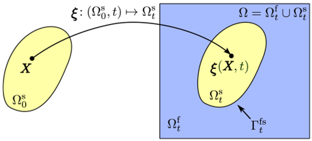
The computational domain Ω includes time-dependent fluid and solid subdomains, and . The solid is described using reference coordinates , and references and current coordinates are connected by the mapping .
2.2. Immersed Lagrangian-Eulerian (ILE) formulation
We now introduce an immersed formulation of FSI that describes the same physical model as the partitioned formulation detailed in Sec. 2.1. As in that formulation, the computational domain is Ω, with x ∈ Ω indicating fixed physical coordinates. As in Sec. 2.1, the structural kinematics are described in Lagrangian form via reference coordinates attached to the solid, and we use the same motion map to determine the physical position of solid material point X at time t. In the immersed formulation, however, we solve the incompressible Navier-Stokes equations on the full computational domain Ω, including both the fluid and solid subdomains. We split the computational domain Ω into an exterior fluid region and an interior fluid region , each parameterized by time t, with superscripts ‘+’ (‘−’) indicating values obtained from the ‘exterior’ (‘interior’) side of the fluid-structure interface. Using this notation, we have and . We extend the definition of the fluid velocity u, pressure p, viscosity μf and stress tensor σf to hold in the entire computational domain Ω, so that the extended fluid stress tensor σf is
| (7) |
Our approach applies a singular surface force density along the fluid-structure interface to impose the kinematic constraint, which implies a discontinuity in the traction associated with the extended fluid stress, σf, along . A jump in a scalar field ψ(x, t) at position x = ξ(X, t) along the interface is denoted by
| (8) |
in which ⟦⋅⟧ indicates the jump in the value across the interface, n(x, t) is the outward unit normal vector (into the exterior fluid region) along , and ψ+(x, t) and ψ−(x, t) are the limiting values approaching the interface position x from the exterior fluid region and interior fictitious fluid region , respectively. By considering the jump in the extended fluid stress, the governing equations are
| (9) |
| (10) |
| (11) |
| (12) |
| (13) |
| (14) |
in which J(X, t) is the surface Jacobian determinant [68], F(X, t) is an interfacial surface force density that is the Lagrange multiplier to maintain the kinematic condition for the constraint in Eq. (12) applied along the fluid-solid interface , and is the exterior fluid traction. Importantly, Eqs. (13) and (14), which account for the dynamic interface condition, imply that only the fluid momentum and stresses from the exterior fluid subregion have any physical effect in driving the dynamics of the structure.
The jump discontinuity in Eq. (11) can be decomposed into discontinuities in the pressure and viscous stress, which in current coordinates are
| (15) |
| (16) |
Higher order jump conditions, including those associated with the first normal derivative of the pressure and the second normal derivative of the velocity, can be also derived [101, 35].
2.3. A penalty approach to the ILE formulation
The formulation introduced in Sec. 2.2 requires the solution of a saddle-point system that couples the Eulerian and Lagrangian variables [54]. To develop a practical numerical method, we relax the kinematic constraint, Eq. (12), by introducing two representations of the fluid-structure interface and applying penalty forces to penalize displacements between the two representations. This penalty method determines an approximate Lagrange multiplier force instead of solving for the Lagrange multiplier to exactly impose the condition [54]. Specifically, along with the mapping ξ(X, t) that determines the kinematics of the structure, we introduce an explicit representation of the fluid-structure interface that is parameterized via χ(X, t) and that moves with the fluid, so that ∂χ(X, t)/∂t = u(χ(X, t), t); see Fig. 2. In this study, we use a penalty formulation similar to one proposed by Goldstein et al. [102], in which the rigidity constraint is approximately imposed through a linear spring-like force via
| (17) |
Figure 2:

(a) The immersed interface domain and (b) the partitioned fluid () and solid () subdomains. (c) In the penalty-ILE method, the configuration of the explicit representation of the fluid-structure interface (determined by χ) conforms to the boundary of the structure (determined by ξ) in an approximate sense. Specifically, the motion of the surface representation is determined by the local fluid velocity at the fluid-structure interface whereas the no-slip condition is satisfied in an approximate sense by spring-like forces that penalize displacements between the two representations of the fluid-structure interface. The displacement between the two representations is exaggerated here for illustration purposes. In practice, we always impose an assertion specifying that the maximum relative displacement is at least less than 0.1 of the Cartesian grid spacing.
Here, κ is the spring stiffness penalty parameter. This force penalizes deviations from the constraint ξ(X, t) = χ(X, t) and, in the discretized equations, acts to ensure that the volumetric and surface meshes are at least approximately conformal in their motion. Note that it is possible to control the discrepancy between the two configurations because as κ → ∞, the formulation exactly imposes the constraint that the two interfaces representations move together.
2.4. Rigid body dynamics
The general formulation for description of kinematics of a rigid body includes both translational and rotational motions of material points in the body. The kinematics in the current configuration coordinates of the solid can be written in terms of reference coordinates as
| (18) |
in which Xc is the position of the center of mass in the reference coordinates, dc(t) is the displacement of the center of mass, and is the rotation matrix. The rotation matrix can be expressed using the Euler angles, ϕ = ϕ(t), θ = θ(t), and ψ = ψ(t), as
| (19) |
here using the x-y-z convention in the rotation order. Following the approach of Akkerman et al. [103], we avoid explicitly forming the Euler angles except for cases where there is only one rotational degree of freedom. As will be presented in Sec. 3, in the time integration of the rigid body dynamics, the rotation matrix is an additional problem unknown that is integrated in time along with the displacement and rotational degrees of freedom. This significantly reduces the complexity of the calculation of the rotation angle for three degree of freedom (3-DOF) problems in two spatial dimensions and six degree of freedom (6-DOF) problems in three spatial dimensions. Using Eq. (18), the rigid body displacement and velocity are respectively defined as
| (20) |
and
| (21) |
Denoting the rigid body center of mass in the current configuration as ξc(t) = ξ(Xc, t) = Xc + dc(t), Eq. (21) becomes
| (22) |
in which
| (23) |
is the skew-symmetric angular velocity matrix. The pseudovector ω(t) = (ω1(t), ω2(t), ω3(t)) can be extracted from this tensor matrix. Using the angular velocity vector, the rigid body velocity field in Eq. (22) can be re-written in terms of ω(t) as,
| (24) |
For a three-dimensional problem, the three components of the translational velocity of the center of mass , together with the three components of the angular velocity ω(t), form the six degrees-of-freedom that completely determine the kinematics of the rigid body.
Linear and angular momentum conservation in the rigid body are described by a system of six ordinary differential equations,
| (25) |
| (26) |
in which m is the mass of the solid object, Fnet(t) is the global force including the sum of all the forces exerted on the rigid body, and Tnet(t) is the net torque vector. is the inertia tensor of the solid body in the current configuration, which is defined in terms of the inertia tensor in the reference configuration, , via
| (27) |
in which is
| (28) |
In our fluid-structure interaction framework, the net force and torque vectors in Eqs. (25) and (26) are computed as
| (29) |
| (30) |
in which V is the volume of the solid object, g is the gravity vector, and is the exterior fluid traction vector exerted on the solid object by the fluid. In the penalty formulation of the ILE method, quantities on the left hand sides of Eqs. (29) and (30) are evaluated on , which moves with the local fluid velocity.
3. Discrete Equations of Motion
This section introduces numerical methods for the penalty formulation of the immersed Lagrangian-Eulerian method detailed in Sec. 2.3. This approach leverages our immersed interface method (IIM) for discrete surface representations [68]. We include only the key aspects of this method; for additional details and benchmarking studies of problems with prescribed motion, see Kolahdouz et al. [68]. Standard methods are used for the rigid body dynamics. A second order accurate Strang time step splitting approach [104] is used to obtain systems of equations that can be treated via efficient linear solvers.
3.1. Eulerian discretization
The incompressible Navier-Stokes equations are discretized on an adaptively refined Cartesian grid using a staggered-grid finite difference discretization [105] in which the pressure is approximated at the centers of the Cartesian grid cells and the components of the velocity are approximated at the centers of the edges (in two spatial dimensions) or faces (in three spatial dimensions) of the grid cells. Standard compact second-order accurate differencing schemes are used for the divergence, gradient, and Laplace operators. The discrete divergence of the velocity D ⋅ u is evaluated at the cell centers, whereas the discrete pressure gradient Gp and the components of the discrete Laplacian of the velocity Lu are evaluated at the cell edges (in two spatial dimensions) or faces (in three spatial dimensions). For the nonlinear advection terms, a staggered-grid version [106, 105] of the xsPPM7 variant [107] of the piecewise parabolic method (PPM) [108] is used. Physical boundary conditions are prescribed along the boundaries of the computational domain Ω as described previously [105, 109]. Adaptive computations use a discretization approach described by Griffith [109] that employs Cartesian grid adaptive mesh refinement (AMR).
To account for the jump conditions along the fluid-solid interface that occur in the ILE formulation, we modify the definitions of Gp and Lu for those stencils that cross the immersed interface. Using generalized Taylor series expansions [29, 35], it can be shown that if the interface cuts between two Cartesian grid points at location xo = (xo, yo, zo), such that xi,j,k ≤ xo < xi+1,j,k, with xi,j,k ∈ Ωf,−, and xi+1,j,k ∈ Ωf,+, then for a piecewise differentiable quantity ψ, we have
| (31) |
| (32) |
in which Δx is the grid spacing in the x direction, ψi,j,k = ψ(xi,j,k), d+ = xi+1,j,k − xo > 0, and nx is the x-component of the normal vector n = (nx, ny, nz) at the intersection point xo. The full implementation of this approach to the three-dimensional incompressible Navier-Stokes equations, including the application of the jump corrections to the stencils of the pressure and the viscous terms and algorithms for identifying intersections between the finite difference stencils and the discrete interface representation, is detailed in our earlier work [68].
3.2. Lagrangian discretization
Let be a triangulation of , the reference configuration of the volumetric rigid body, composed of elements Ue such that , in which e indexes the mesh elements. We take to be the positions of the M nodes of the mesh in the reference configuration, to be the current positions of the nodes, and to be the corresponding interpolatory nodal (Lagrangian) basis functions. A continuous description of the configuration of the structure is defined by
| (33) |
The configuration of the fluid-structure interface representation that moves with the fluid is described by the mapping . To obtain a discrete representation of this interface, we use a surface mesh that corresponds to the restriction of the volumetric solid mesh to . For the discrete representation of the fluid-structure interface we have
| (34) |
except that in practice, we only need to evaluate this sum over the lower-dimensional subset of nodes that are located on surface mesh, and not over all of the nodes in the volumetric representation. The reason is that the interpolatory (nodal) basis functions associated with interior nodes vanish on the surface. Similarly, the surface force density is determined by
| (35) |
Again, this sum only needs to be evaluated using the Mfs surface nodes. In an implementation, it is straightforward to use separate data structures for the volumetric and surface structural meshes. For the remainder of the paper, we adopt the convention that all computations involving the surface representation are performed using only a surface mesh with appropriate nodal degrees of freedom and surface-restricted basis functions.
Stress jump conditions are imposed by evaluating the correction terms from the interfacial forces and interface configuration (i.e. generalizations of Eqs. (31) and (32)). Geometrical quantities, including the surface normals and surface Jacobian determinant, that are needed by the IIM discretization, are obtained by directly differentiating Eq. (33). Note, however, that the standard nodal basis functions are C0 but not C1 at element boundaries, and so quantities that are obtained in terms of ∂χh/∂X are discontinuous in both the reference and current configurations. In particular, the pointwise jump conditions determined from the mesh geometry and the surface Jacobian J are generally discontinuous between the elements. Following the approach introduced in our prior work [68], we obtain a continuous approximation to the jump conditions through the L2 projection. Briefly, given a function , its L2 projection Phψ onto the subspace is defined by requiring Phψ to satisfy
| (36) |
The L2 projection of a vector-valued quantity is determined component-wise. Because the L2 projection is defined via integration, the function ψ does not need to be continuous or even to have well-defined nodal values. By construction, however, Phψ will inherit any smoothness provided by the subspace Sh. In particular, for C0 Lagrangian basis functions, Phψ will be at least continuous. In our numerical scheme, we separately compute the projection of the normal and tangential components of the surface force per unit current area, J−1Fh(X, t), onto Sh, as needed to specify the conditions for the pressure and the viscous stress. We drop the subscript “h” in the remainder of the paper to simplify notation. To solve for the projected jump conditions, linear systems of equations involving the mass matrix need to be solved, in which has components . Eq. (36) is evaluated using seventh-order Gaussian quadrature. Notice that these projections are computed only along the fluid-solid interface and involve only surface degrees of freedom. Consequently, the computational cost of evaluating these projections is asymptotically smaller than the solution of the fluid equations. Note also that similar to the conventional IB method, a force-spreading operator can be defined to evaluate and apply the correction terms to the Eulerian discretization via a discrete Eulerian force density [68].
The velocity of the fluid-structure interface representation that moves with the fluid is determined by evaluating the Eulerian velocity u(x, t) on the interface. As detailed previously [68], it is possible to interpolate the discretized Eulerian velocity field u to the Lagrangian interface mesh using a corrected bilinear (or, in three spatial dimensions, trilinear) interpolation scheme that accounts for the known discontinuities in ∂u/∂n. In general, however, the basic interpolation scheme will produce an interface velocity field that is not in the space of the nodal basis functions, which implies that it cannot be used directly to update the configuration of the interface. To obtain a suitable surface mesh velocity field, we project the interpolated velocity field onto the space spanned by the nodal basis functions using Gaussian quadrature. This procedure implicitly defines a velocity-restriction operator , so that .
The FSI coupling approach used herein crucially relies on the accurate evaluation of the exterior fluid traction. This requires evaluating the exterior fluid pressure and exterior viscous shear stress. To evaluate the exterior pressure at a position , we use
| (37) |
in which is the interior pressure interpolated to a position x− away from the interface in the opposite direction of the normal vector n and at a distance equal to 1.3 times the diagonal size of one grid cell. This factor has been chosen on an empirical basis [68]. Here, is the unmodified bilinear (or trilinear) interpolation operator involving quantities on one side of the interface. To evaluate the exterior wall shear stress, a one-sided approximation to the normal derivative of the velocity is calculated using the same interfacial velocity reconstruction procedure that is used to determine the interface velocity along with the velocity value at a neighboring location in the direction of the normal vector x+. As with the pressure, unmodified bilinear (or trilinear) interpolation is used to obtain the velocity away from the interface. A one-sided finite difference formula is used to calculate the normal derivative,
| (38) |
in which the distance is chosen to be slightly larger than the diagonal size of the Cartesian mesh (1.05 times the diagonal size), so that regular bilinear (or trilinear) interpolation can be used to evaluate ensuring that the interpolation only uses values on one side of the interface. It is possible to use a second-order formula with a three-point stencil which requires interpolating an additional point in the normal direction, but preliminary numerical experiments (data not shown) suggest the computation using only two points is more stable. Moreover, as shown previously [68], this simple scheme is adequate to achieve a point-wise first-order accurate approximation to the wall shear stress. Note that as with velocity interpolation, the pressure and wall shear stress can be evaluated at arbitrary locations along the interface. We also use a surface-restricted L2 projection to obtain nodal values of these interfacial quantities.
3.3. Time integration scheme
In advancing from time step n at time t to time step n + 1 at time t + Δt, we define a vector of variables Υ that includes all of the Eulerian and Lagrangian quantities that need to be updated as Υ = [u, p, χ, dc, dc, ω, , ]. We use the second order Strang splitting scheme [104], in which within three steps we: 1) solve the rigid body dynamics equations over a half time step Δt/2, treating the fluid traction as constant in time; 2) solve the IIM/FSI equations over a full time step Δt, treating the configuration of the solid as constant in time; and 3) solve the rigid body dynamics equations over a final half time step Δt/2, treating the fluid traction as constant in time. The details of the time stepping for the rigid body dynamics equations, the IIM/FSI equations, and the overall algorithm are given below.
3.3.1. Rigid body time integration scheme
Although we ultimately employ a time step splitting approach that advances the rigid body configuration in two half-steps, to simplify the discussion, the approach for a fixed time step size Δt is detailed here. Denote by the action of the Lagrangian rigid body dynamics solver over the time increment Δt that acts on a solution vector Υ. This solution vector includes all of the Eulerian and Lagrangian variables, but only advances the volumetric structural variables dc, , ω, , and while keeping the remaining variables fixed. Briefly, discretizations of Eqs. (26)–(27) are solved over the time increment Δt to obtain , , ωn+1,k, and via
| (39) |
| (40) |
| (41) |
| (42) |
Eqs. (41) and (42) can be solved through a few subiterations to obtain the new rotation matrix and the angular velocity ωn+1; starting from , and ωn+1,k=1 ≡ ωn at each time step, subiterations are performed by looping over k until with ϵ = 10−8. These iterations are inexpensive, and between one and three are typically needed to reach the convergence criteria. Seventh-order Gaussian quadrature rules are used to approximate integrals on the left side of Eqs. (40) and (42). The updated configuration of ξ(X, t) is then evaluated using Eq. (18). Similarly, the moment of inertia is determined using a discretization of Eq. (27),
| (43) |
3.3.2. IIM time integration scheme
Starting from χn and un at time tn and at time , we compute χn+1, un+1, and . Denote by the action of the IIM solver over a full time step that acts on the solution vector Υ that includes all of the Eulerian and Lagrangian variables but only advances u, p, and χ. Briefly, using the discrete velocity restriction operator , we first obtain initial approximations to the interface position at time via
| (44) |
| (45) |
Next, we solve for χn+1, un+1, and via
| (46) |
| (47) |
| (48) |
in which is obtained from a high-order upwind spatial discretization of the nonlinear convective term u ⋅ ∇u [105], and is the velocity restriction operator at the half time step configuration. This time stepping scheme requires only linear solvers for the time-dependent incompressible Stokes equations. We solve this system of equations by the flexible GMRES (FGMRES) algorithm with a preconditioner based on the projection method that uses inexact subdomain solvers [105]. In the initial time step, a two-step predictor-corrector method is used to determine the velocity, deformation, and pressure; see Griffith and Luo [110] for further details.
3.3.3. Fluid-structure interaction time stepping scheme
For the solution vector Υ over one time step using the Strang splitting scheme we have,
| (49) |
With this time-staggered approach, the overall algorithm to solve the fluid-structure problem is
Step I: Solve the rigid body dynamics in Eqs. (39)–(42) over a half time step Δt/2 to advance from step n to and obtain , , and , and the new position of the volumetric Lagrangian mesh.
Step II: Calculate the penalty force using the most recent position of the volumetric solid mesh and the surface mesh that moves with the fluid.
Step III: Solve for the IIM subsystem in Eqs. (46)–(48) over a full time step and obtain the updated Eulerian velocity field un+1 and pressure as well as the the Lagrangian velocity and positions χn+1 of the surface mesh and the exterior fluid traction forces .
Step IV: Using the exterior fluid traction force from Step III, solve the rigid body dynamics in Eqs. (39)–(42) over a half time step Δt/2 to advance from step to n + 1 and obtain dcn+1, , ωn+1 and .
Step V: Move the Lagrangian mesh of the bulk solid and obtain the new positions ξn+1.
4. Numerical examples
This section presents computational examples to characterize the performance of the present methodology in two and three spatial dimensions. As a demonstration of the method’s ability to tackle more challenging problems, applications to two biomedical models are also presented, including simulations of the dynamics of a bileaflet mechanical heart valve in a pulse duplicator system and the transport of blood clots in a patient-averaged anatomical model of the inferior vena cava. Where possible, comparisons are made to available experimental or computational results. We begin by considering model problems involving a limited number of translational, but not rotational, degrees of freedom (DOF). We systematically increase the complexity of the tests by incorporating additional translation and rotational degrees of freedom. We also consider both smooth immersed structures as well as structures with sharp corners. The fluid-solid interface representation that moves with the fluid is discretized either by piecewise-linear (P1) elements for two-dimensional cases, or by piecewise linear (P1) or piecewise bilinear (Q1) elements for three-dimensional cases. Unless otherwise noted, the structural meshes are constructed so that the ratio of the Lagrangian element size to the Eulerian grid spacing, denoted by Mfac, is Mfac ≈ 2 at least along the fluid-structure interface. In all cases, the Eulerian domain is discretized using an adaptively refined grid. The Cartesian grid spacing on the finest level of the locally refined grid is hfinest = r−(N−1)hcoarsest, in which hcoarsest is the grid spacing on the coarsest level, r is the refinement ratio, and N is the number of refinement levels. The spring penalty parameters are computationally determined as approximately the largest values allowed by our explicit time stepping algorithm at the time step sizes used in the simulations. In each case, the penalty parameter values are tuned using bisection. Unless otherwise noted, centimeter-gram-second (CGS) units are used. For models involving gravitational forcing, gravitational acceleration is set to g = 981 cm · s−2. The large scale three-dimensional simulations in Secs. 4.4, 4.6, 4.7, and 4.8 were performed using the Dogwood cluster provided by the Research Computing Division of University of North Carolina at Chapel Hill Information Technology Services. Each node is comprised of 2.4 GHz Intel Xeon E5-2699Av4 processors with the Broadwell-EP micro-architecture, 512 GB memory, and 44 cores per node, and nodes are connected by a high bandwidth Infini-band EDR switching fabric. The smaller benchmark models are run on a workstation with two 32-core Intel Xeon E5-2680 v3 2.5 GHz processors and 32 GB of memory.
4.1. Vortex-induced vibration of a cylinder
The problem of viscous flow past an elastically mounted two-dimensional cylinder undergoing vortex-induced vibration (VIV) has been widely studied both numerically and experimentally because of its broad range of engineering applications and its interesting vortex dynamics. This problem has also seen substantial use in benchmarking FSI algorithms [3, 111, 19, 88, 112, 113]. Here we consider two separate cases in two spatial dimensions, one using a single vertical degree of freedom, and the second with two degrees of freedom (2-DOF). The governing equations for the 2-DOF cylinder motion are
| (50) |
| (51) |
in which and are the horizontal and vertical displacements of the center of mass, Ms is the mass per unit length of the cylinder, Cs and Ks are the damping and stiffness constants characterizing the spring, and fx and fy are the instantaneous drag and lift forces, respectively. To facilitate comparisons to previous work, we define the non-dimensional horizontal and vertical displacements of the cylinder center in the streamwise and transverse directions, respectively, as and , in which D is the diameter of the cylinder. Taking U∞ as the free stream flow velocity, the mass ratio and reduced velocity are respectively defined as m* = ρs/ρf and U* = U∞/(fnD), in which is the natural frequency of the structure. The damping ratio is .
4.1.1. 1-DOF transverse oscillation
We first consider the benchmark problem of a circular cylinder undergoing VIV with a single vertical degree of freedom. We are interested in capturing the well characterized vortex “lock-in” phenomenon observed in previous studies [114, 3, 19, 111]. Within the lock-in regime, the vortex shedding frequency is close to the natural frequency of the structure, which results in large amplitude vibrations. Physical parameters are selected to match benchmark results in the literature. A schematic of the simulation setup is shown in Fig. 3(a). The computational domain is Ω = [−30 cm, 45 cm] × [−30 cm, 30 cm], a rectangle of size Lx × Ly = 75 cm × 60 cm. The cylinder has diameter D = 1 cm, is initially at rest and centered at the origin. A uniform inflow velocity U = (U∞ = 1 cm ⋅ s−1, 0 cm ⋅ s−1) is imposed on the left boundary (x = −30 cm), and zero normal traction and tangential velocity outflow conditions are imposed at the right boundary (x = 45 cm). Along the bottom (y = −30 cm) and top (y = 30 cm) boundaries, zero normal velocity and tangential traction are imposed. The domain is discretized using N = 6 nested grid levels, with coarse grid spacing hcoarsest = Ly/64 = 0.9375 cm and refinement ratio r = 2 between levels, leading to hfinest ≈ 0.029 cm. With Mfac = 2, this results in approximately 54 linear elements around the perimeter of the disk. The time step size is Δt = (0.1 s ⋅ cm−1) hfinest with a penalty spring constant κ = (0.00125 g ⋅ cm−2)/Δt2. The Reynolds number Re = ρfU∞D/μf is fixed at 150, the damping is set to zero (ζ = 0), and the mass ratio is m* = 8/π.
Figure 3:
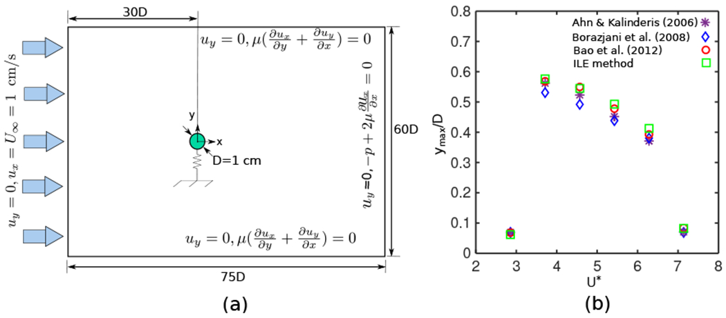
(a) Schematic diagram of the computational domain and boundary conditions for flow around an elastically mounted rigid circular cylinder (Sec. 4.1.1). (b) Maximum transverse displacement of the oscillating cylinder (Sec. 4.1.1) for different values of U* with m* = 8/π, Re = 150, and ζ = 0. Results from the present ILE approach fall within the range of values reported in previous studies.
First, the effect of the reduced velocity on the maximum displacement of the cylinder is studied by systematically varying U* within the range 3 ≤ U* ≤ 8. Vortex shedding occurs in all cases. Fig. 3(b) shows the maximum displacement with respect to U*. These results demonstrate that for U* ∈ [4, 7] there is a large increase in the vibration amplitude. Fig. 3(b) also compares results obtained by our method to previous numerical studies, including a geometrically conservative finite volume ALE method [3], a curvilinear immersed boundary method [19], and a finite element based ALE approach [111]. Excellent agreement is obtained over the full range of U* values considered here.
In addition, we perform a grid refinement study using the reduced velocity with the largest maximum displacement (i.e. U* = 4) while fixing the previous values of all other parameters. To achieve this in our AMR framework, we vary the number of refinement levels N between 5 and 7. Fig. 4 shows the time-history of the maximum displacement for N = 5, 6, and 7 levels of refinement. The displacement values obtained for N = 6 and 7 closely match each other, whereas the coarser case, using N = 5 levels of refinement, under-predicts the maximum displacement in the vortex shedding region. Notice that these results indicate that using N = 6 levels of refinement provides essentially grid-converged results for this benchmark problem.
Figure 4:
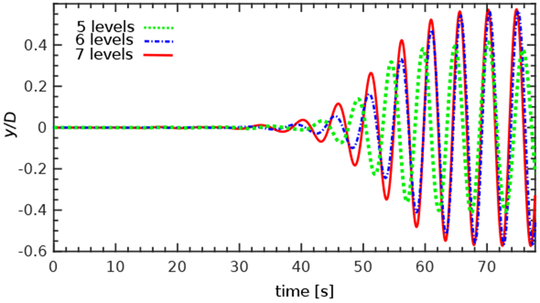
Time history of the transverse displacement of the oscillating cylinder (Sec. 4.1.1) under grid refinement. Simulation parameters include U* = 4, m* = 8/π, Re = 150, and ζ = 0.
4.1.2. 2-DOF oscillation
The 2-DOF oscillation is studied using the same physical parameters as Blackburn and Karniadakis [114], who used a spectral element approach. The size of the computational domain, the cylinder diameter and initial position, and the physical boundary conditions are all the same as the 1-DOF example in Sec. 4.1.1. The Reynolds number is Re = 200, the reduced velocity is U* = 0.5, the damping ratio is ζ = 0.01, and the mass ratio is m* = 4/π.
We use this example to investigate the order of spatial convergence of the difference in the displacement between the two Lagrangian representations (i.e. the fluid-structure interface representation that moves with the fluid, and the surface of the volume mesh). As discussed in Sec. 2.3, the two representations are tethered together by spring-like forces that penalize relative motion between them. The Cartesian grid spacing on the coarsest level for all four cases is hcoarsest = 60/64 cm. We consider four sets of discretizations, ranging from a very coarse composite grid with N = 4 levels of refinement to a reasonably fine grid with N = 7 levels of refinement, using refinement ratio r = 2 between levels. The penalty spring constant is κ = (0.125 g·s−2)/h2, and a small constant time step size Δt = 0.001 s is chosen for all cases. In our recent work [68], it was shown that the present IIM algorithm yields second-order convergence in the displacement of the interface in both L2 and L∞ with suitable scalings for the penalty parameter κ. As in our previous work, for the choice of the κ used here, pointwise second order convergence is also expected for the displacement between the positions of the two interface representations. Fig. 5 shows ‖ξ(X, t) − χ(X, t)‖∞, the L∞ norm of the discrepancy between the Lagrangian points at the surface mesh and the corresponding points on the boundary of the volume mesh. Fig. 5(a) indicates that the method converges at second order in the maximum norm at t = 55 s. To investigate the change of the L∞ norm of the error over time, this value is plotted on a semi-log scale in Fig. 5(b) for the four discretizations. The overall behavior of the error norm remains consistent for all discretizations throughout the entire simulation. Note that the difference shown in ξ(X, t) − χ(X, t) is proportional to the tethering penalty force that connects the two representations. Because of the periodic “figure-of-eight” nature of the cylinder’s dynamics, a undulatory pattern in the loading force is to be expected over time. This pattern is expected to be present in ‖ξ(X, t) − χ(X, t)‖ difference as well due to its proportionality with the force. Specifically if we wish to achieve ‖ξ(X, t) − χ(X, t)‖ = O(h2), it is necessary that the penalty parameter κ also satisfies κ = O(1/h2), so that an applied penalty force of the form F = κ(ξ(X, t) − χ(X, t)) satisfies ‖F‖ = O(1) under grid refinement [68].
Figure 5:
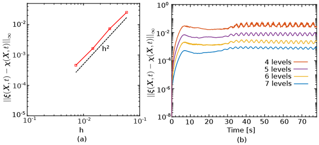
Spatial convergence of the difference in the displacement between the two Lagrangian representations (Sec. 4.1.2). (a) L∞ norm of the difference between the positions of the two representations of the fluid-structure interface after the onset of the vortex shedding at t = 55 s. (b) Time history of the L∞ difference, indicating a consistent behavior for all discretizations throughout the simulation.
As another verification, the centerline displacement response of the cylinder is compared to the numerical results of Blackburn and Karniadakis [114]. It is expected that the vortex shedding of the oscillating cylinder will lead to a periodic “figure-of-eight” behavior. This is shown in Fig. 6 for three locally refined Cartesian grids with N = 5, 6, and 7 levels along with the solution from Blackburn and Karniadakis [114]. The trajectory clearly converges under grid refinement. Moreover, the trajectory of the cylinder for the finest discretization agrees extremely well with the spectral element solution [114]. The origin of oscillations xc, which is defined as the intersection point in the periodic figure-of-eight trajectory of the cylinder’s center of mass, and the Strouhal number, which is calculated as St = fD/U∞ with f representing the oscillation frequency, are reported in Table 1 for the finest ILE computation (N = 7) along with the results of Blackburn and Karniadakis and several other studies. The center of oscillations agrees very well with the original work of Blackburn and Karniadakis [114]. Moreover, the Strouhal number matches the values reported from studies by Yang et al. [88], Yang and Stern [112], Kim et al. [113], and Qin et al. [59]. The centerline trajectory and the dimensionless displacement-velocity phases of x/D − ux/U∞ and y/D − uy/U∞ for this case are shown in Fig. 7. The phase response obtained from our solution agrees well with previous observations reported by Yang and Stern [115] and Liu and Hu [116].
Figure 6:
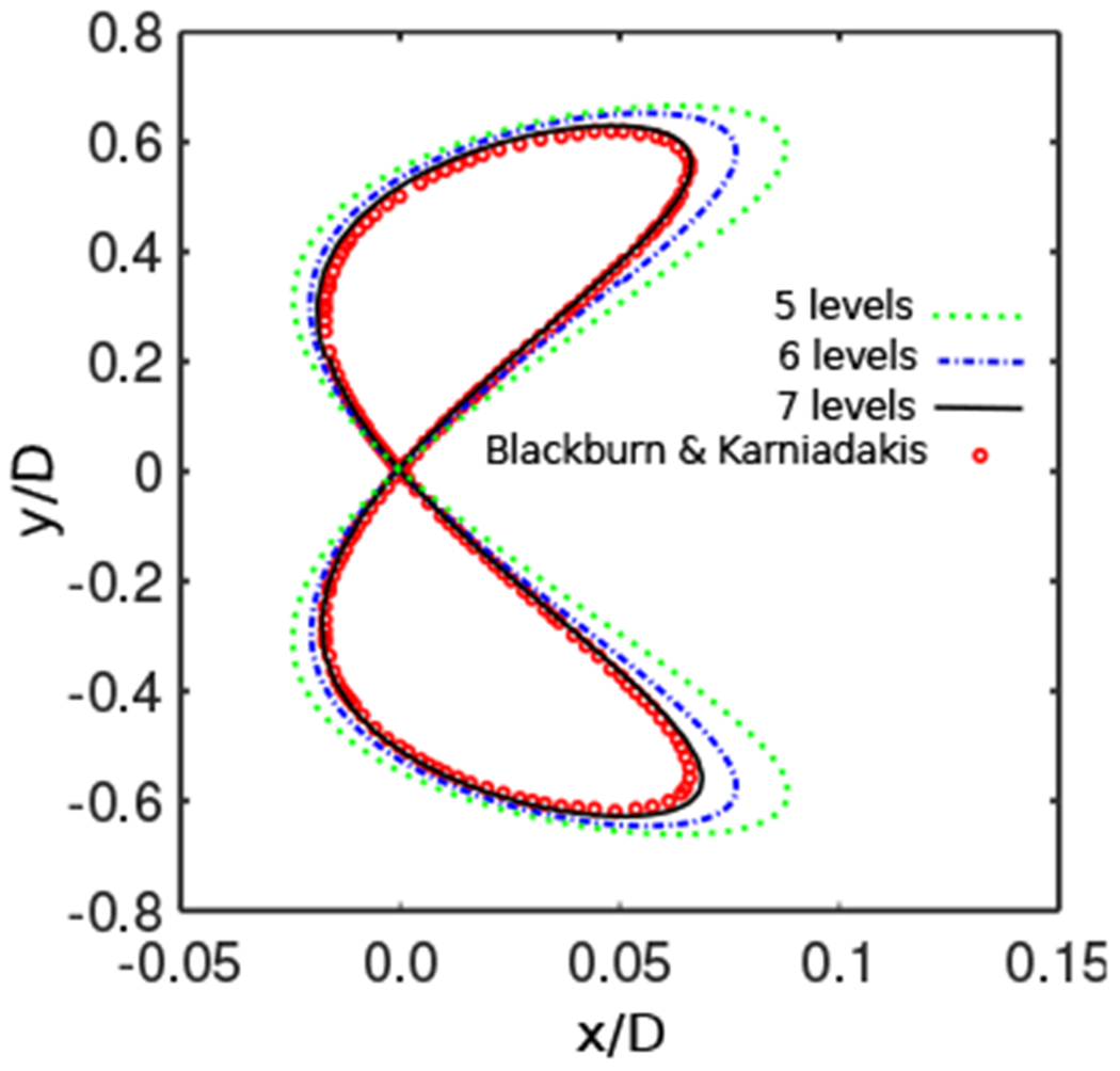
Centerline displacement response of the 2-DOF elastically mounted rigid cylinder (Sec. 4.1.2) under grid refinement. There is excellent agreement between the ILE result on the finest grid and the results of Blackburn and Karniadakis [114] using a high order spectral element method. Simulation parameters include U* = 5, m* = 4/π, Re = 200, and ζ = 0.01.
Table 1:
Dimensionless origin of oscillation (xc/D) and the Strouhal number (St) for the 2-DOF elastically mounted rigid cylinder (Sec. 4.1.2). Simulation parameters include m* = 4/π, U* = 5, ζ = 0.01, and Re = 200, which generate vortex-induced vibrations (VIV).
Figure 7:
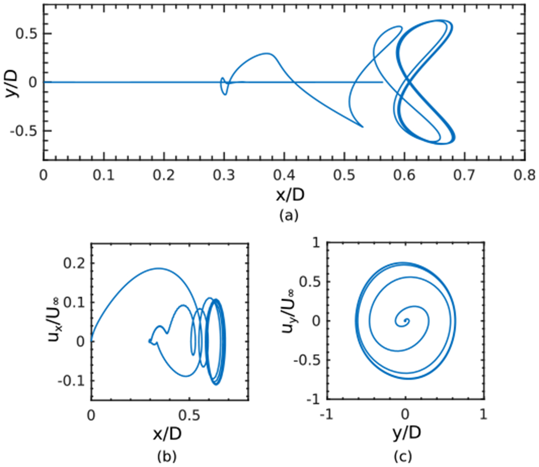
Phase plots of the center of mass displacement and velocity responses for an elastically mounted cylinder with mass ratio of m* = 4/π (Sec. 4.1.2). Other simulation parameters include U* = 5, ζ = 0.01, and Re = 200.
4.1.3. 2-DOF oscillation with low mass ratio
We now briefly consider significantly lower mass ratios than the one studied above. We first consider a case with density ratio of m* = 0.4/π, which is 10 times smaller than the first example. The remainder of the simulation parameters are identical to the finest case in the previous example (Sec. 4.1.2). Fig. 8(a) shows that the cylinder travels more than 7 diameters downstream before undergoing the same periodic figure-of-eight motion. Fig. 8 also reveals that the oscillations for this light cylinder occur at a higher amplitude and with larger horizontal and, to a lesser extent, vertical velocity magnitudes. Fig. 9 shows the instantaneous vorticity contours around this light structure at six time points. Vortex shedding is observed, with two vortices shed during one cycle of the quasi-periodic oscillation. The wake footprint and the associated vorticity patterns also indicate that the cylinder is undergoing periodic motion. Notice that previous work has reported severe instabilities in computing such cases using both weak and strong coupling approaches [113]. The present method appears to remain stable even for extremely light structures. Table 2 reports the center of oscillations along the x-axis for a wide range of mass ratios along with the results of Kim et al. [113], the only other study that we are aware of to also consider such low mass ratios. To the authors’ knowledge, results obtained using mass ratios smaller than 0.3 have not been previously reported for this benchmark case. The present method yields a slightly larger distance than the work of Kim et al. [113] for the origin of the oscillations. In the work of Kim et al. [113], the mass ratio of m* = 0.3 was reported as the lowest ratio for a stable solution using a strong coupling approach. The present method is able to predict the dynamics at substantially smaller mass ratios (nearly two orders of magnitudes smaller) as shown for m* = 0.005 in Table 2. Although stable results were obtained for lower density ratios, the accuracy of the dynamics requires further validation that can be performed once additional experimental data are available. Note that to accommodate the extended horizontal movement of the cylinder for m* < 0.1, the computational domain for these cases was changed to Ω = [−120 cm, 180 cm] × [−120 cm, 120 cm], a rectangle of size Lx × Ly = 300 cm × 240 cm. To keep the grid spacing the same as before, N = 8 nested grid levels were used, and the Cartesian grid spacing on the coarsest level was set to hcoarsest = Ly/64.
Figure 8:
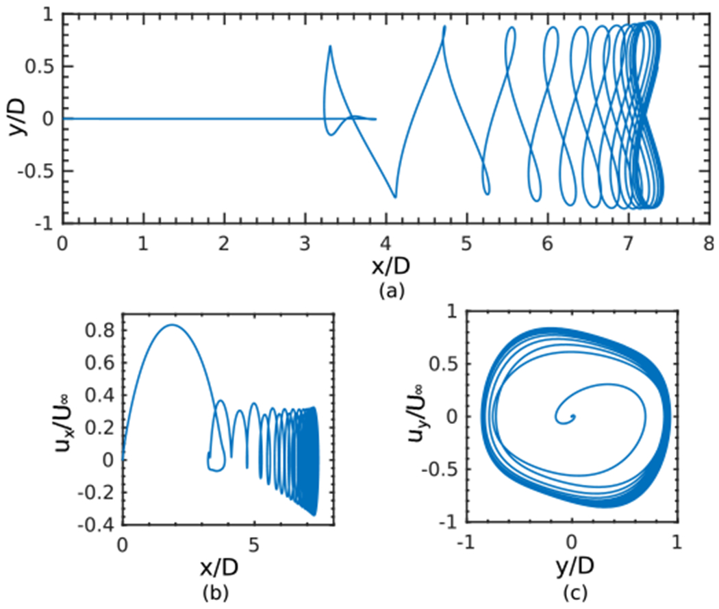
Phase plots of the center of mass displacement and velocity responses for an elastically-mounted cylinder (Sec. 4.1.3) with a low mass ratio m* = 0.4/π. Other simulation parameters include U* = 5, ζ = 0.01, and Re = 200.
Figure 9:
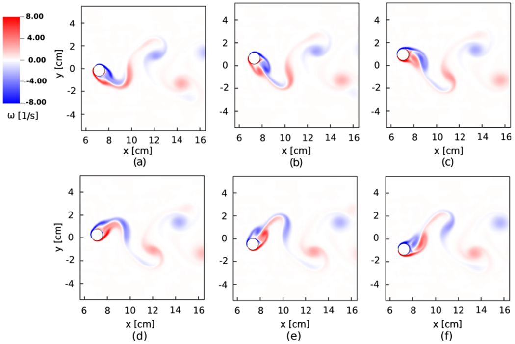
Vorticity field of the 2-DOF oscillating cylinder (Sec. 4.1.3) with low mass ratio m* = 0.4/π at times (a) t = 178.82 s, (b) t = 179.82 s, (c) t = 180.82 s, (d) t = 181.82 s, (e) t = 182.82 s, and (f) t = 183.82 s.
Table 2:
Dimensionless origin of oscillation (xc/D) for low and very low mass ratios of the 2-DOF elastically mounted rigid cylinder (Sec. 4.1.3).
| m* = 0.3 | m* = 0.2 | m* = 0.1 | m* = 0.05 | m* = 0.01 | m* = 0.005 | |
|---|---|---|---|---|---|---|
| Kim et al. [113] | 2.27 | - | - | - | - | - |
| ILE method | 2.83 | 4.41 | 9.39 | 19.01 | 91.50 | 160.10 |
4.1.4. Stability and sensitivity studies for κ
Because we use an explicit time stepping approach to couple the fluid and solid degrees of freedom, if we fix the spatial and temporal discretization parameters, there will be a largest stable value of the penalty spring parameter κ. As mentioned at the beginning of Sec. 4, in practice, we compute using values of κ close to the stability limit, which we approximately determine using the method of bisection. To study the sensitivity of the numerical algorithm to the penalty parameter κ and the influence of this parameter on the accuracy of the computed solution, we reconsider the 2-DOF vortex-induced vibration of a light cylinder with density ratio of m* = 0.4/π (Sec. 4.1.3). Except for the values of κ and the time step size Δt, all other simulation parameters are the same as Sec. 4.1.3. We use a locally refined grid with N = 7 levels of refinement, and the final simulation time is t = 200 s, which is long after vortex induced vibration has been established. We computationally determine minimum and maximum values of κ that 1) satisfy a minimum threshold in displacement between the two Lagrangian representations, and 2) remain stable. Accuracy thresholds are determined to be the minimum values of κ required to achieve tolerances of 0.1 hfinest, which is commonly used in IB models of rigid structures, along with a tighter tolerance of 0.06 hfinest. The maximum stable value of κ determines a stability threshold. Fig. 10(a) shows the computationally determined accuracy and stability thresholds for this case. Because it is not practical to determine the precise values of these thresholds across all time step sizes, error bars indicate the small uncertainty in the lower and upper bounds. For the smallest time step size considered here, the range of values of κ that satisfy both criteria spans nearly three orders of magnitude, from the minimum value that achieves the minimum accuracy criterion to the maximum value that results in a stable computation with 0.06 hfinest displacement threshold. For the largest time step, there is at least about three-fold difference between the minimum and maximum values of κ. Fig. 10(b) shows the effect of κ on the ratio between the maximum norm of the two Lagrangian representations and the finest grid spacing for three stable spring constants of κ = 500, 1000, and 1400 using the time step Δt = 0.001. Notice that the maximum displacement between the representations scales like κ−1. Fig. 10(c) shows the trajectory of the center of mass of the cylinder for the same three κ values. Deviations in the trajectories are small and converge as κ increases. It is worth noting that the maximum discrepancies for the highest and lowest choices of κ are less than the spacing on the finest grid level, hfinest.
Figure 10:

Impact of the penalty parameter κ on the computed dynamics for the 2-DOF elastically mounted light cylinder (Sec. 4.1.4). Other simulation parameters in these computations are m* = 0.4/π, U* = 5, ζ = 0.01, and Re = 200 (a) Accuracy and stability thresholds of κ for a range of time step sizes, (b) The ratio between the maximum norm of the difference in the positions of the two Lagrangian representations to the finest Cartesian grid spacing over the entire course of the simulation, determined using Δt = 0.001 and κ = 500, 1000, and 1400. (c) Centerline displacements of the cylinder for the three values of κ highlighted in panel (b).
4.2. Galloping rectangular structure
This example uses a rectangular plate undergoing galloping motion to test the accuracy of the method for models involving only rotational degrees of freedom. Flow-induced rotational galloping oscillations occur in many areas of structural [117], aeronautical [118], and mechanical [119] engineering applications. This problem has also been widely used as a benchmark problem to validate numerical algorithms [96, 115, 112]. In this section, only a single rotational degree of freedom is used, and the translational heave (horizontal) and surge (longitudinal) motions are eliminated. The governing equation for the mass-spring-damper model with one rotational degree of freedom is
| (52) |
in which θ is the rotational angle of the body, is the rotational moment of inertia, is the torsional damping constant, is the torsional spring constant, and Mθ is the moment acting on the rigid structure from exterior fluid forces. In our simulations, we consider a rectangular structure with a width-to-thickness ratio of Λ = L/H = 4. To enable comparisons with prior studies, we define the non-dimensional moment of inertia by , the non-dimensional damping ratio by , and the reduced velocity by U* = U∞/(fθH). In the latter formula, U∞ is the free stream velocity and is the natural frequency of the body. Following the work of Robertson et al. [96], the non-dimensional parameters are taken to be , U* = 40, and . A schematic of the computational setup and the boundary conditions is given in Fig. 11(a). The rectangular structure is centered at the origin with an initial zero angular velocity and a non-zero angle of θ0 = 1°. The computational domain is Ω = [−32 cm, 96 cm] × [−32 cm, 32 cm], a rectangle of size Lx × Ly = 128 cm × 64 cm. The domain is discretized using N = 4 nested grid levels, with coarse grid spacing hcoarsest = Ly/32 = 2.0 cm and refinement ratio r = 4 between levels, leading to hfinest = 0.0625 cm. A uniform inflow velocity of U = (U∞ = 1 cm · s−1, 0 cm · s−1) is imposed on the left boundary (x = −32 cm). Using the free stream velocity, the Reynolds number Re = ρfU∞H/μf is set to 250. A penalty spring constant of κ = 400 g · cm−2 · s−2 is used, and the time step size is Δt = (0.02 s · cm−1) hfinest. Zero normal traction and tangential velocity are imposed at the right boundary (x = 96 cm). Along the bottom (y = −32 cm) and top (y = 32 cm) boundaries, the normal velocity and tangential traction are set to zero. Fig. 11(b) shows the time history of the pitch angle of the galloping rectangle for the damped oscillation of the structure. Once the vortex shedding state is established, the structure starts to undergo a periodic rotation with well-characterized frequency and upper bound of the maximum angle. This behavior is clearly captured by the present method. Fig. 11 panels (c)–(e) show snapshots of the structural rotation along with the vortex structure of the flow at three different times.
Figure 11:
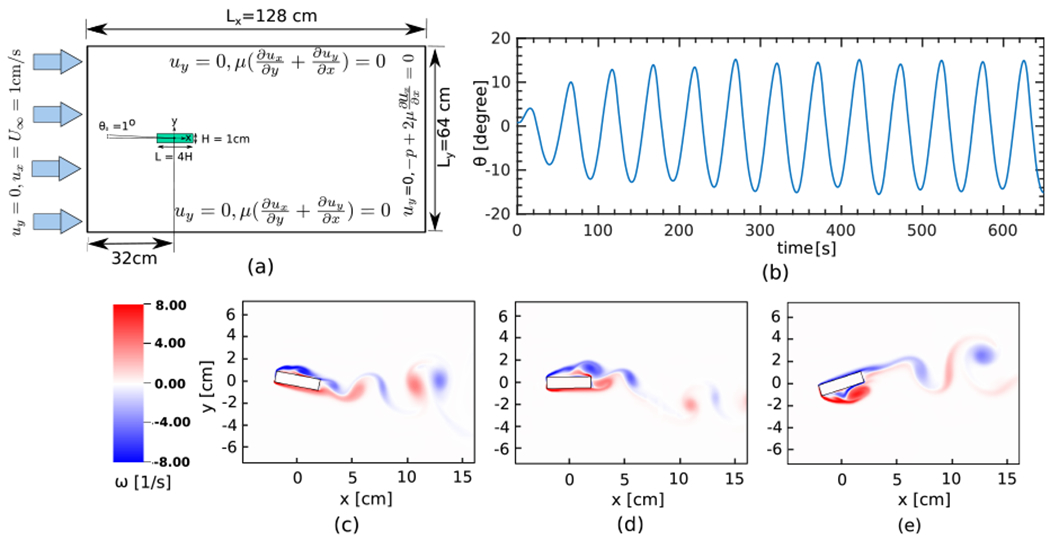
(a) Schematic diagram of the computational domain and boundary conditions for the galloping rectangle (Sec. 4.2) with . (b) Pitch angle (θ) as a function of time. (c)–(e) Vorticity field at times t = 293.9 s, t = 305.9 s, and t = 321.9 s, respectively.
To demonstrate the ability of the algorithm in modeling larger rotational angles, an additional case is considered with . The initial angle is set to θ0 = −5°. All the other parameters, including the time step size and penalty spring constant, are the same as before. As seen in Fig. 12(a), the method generates periodic behavior with maximum galloping amplitude of approximately θmax = 124°. Fig. 12 panels (b)–(d) show the flow patterns around the structure at three different times.
Figure 12:
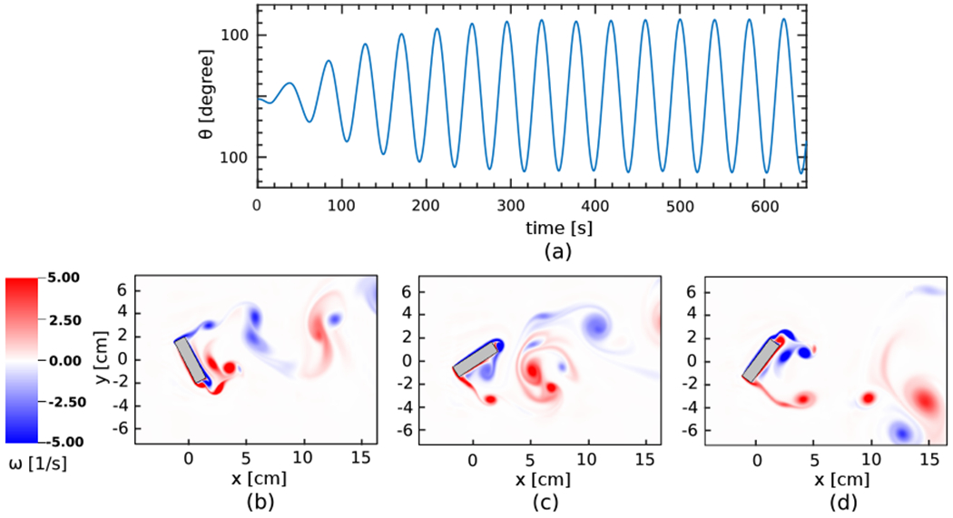
Representative results for the galloping rectangle with zero damping (). (a) Pitch angle (θ) as a function of time. (b)–(d) Vorticity field at times t = 377.9 s, t = 385.9 s, and t = 397.8 s, respectively. Here both the bulk region (shown in gray) and the surface mesh of the structure (shown in black) are illustrated to show the effectiveness of the coupling approach and to confirm that the two representations move together.
To compare the rotational response of the structure with previous work, the maximum pitch angle and frequency for the above two cases are reported in Table 3 along with values from other studies. The work of Robertson et al. [96] uses a body-fitted spectral element method in a non-inertial reference frame. The methods used by Yang and colleagues [115, 112] are different variations of a strongly-coupled direct forcing approach with a field extension strategy for the pressure/velocity derivatives. Table 3 demonstrates excellent quantitative agreement of both vortex shedding characteristics of θmax and the galloping frequency fθ for the two cases in comparison with other numerical studies.
Table 3:
Comparison of the maximum pitch angle (θmax) and galloping frequency (fθ) for the galloping rectangular structure (Sec. 4.2) with zero damping () and non-zero damping ().
4.3. Freely falling rectangular plate
We now consider a model of a falling rigid plate in a water tank that is based on the experiments by Andersen et al. [97]. This example tests the action of the instantaneous fluid forces on an object with sharp corners that leads to extremely complex trajectories. This benchmark case has also been investigated in the context of fluid-structure interaction algorithms in prior studies [120, 115, 116]. We consider two cases from Anderson et al. [97], one undergoing fluttering motion at Re = 1147 and the other undergoing tumbling motion at Re = 837. Different modes of fluttering and tumbling motions are captured in both the experiments [97] and the simulations.
4.3.1. Fluttering motion
For the case of a freely fluttering plate, the plate thickness is taken to be H = 8.1 × 10⁻² cm with width-to-thickness ratio of Λ = L/H = 14. The density of the plate and fluid are ρs = 2.7 g · cm−3 and ρf = 0.997 g · cm−3, respectively. To achieve a Reynolds number of Re = 1147, the fluid viscosity is set to μf = 8.87 × 10⁻³ g · cm−1 · s−1. A schematic of the problem setup is shown in Fig. 13(a). The computational domain is Ω = [−40 cm, 40 cm] × [−56 cm, 24 cm], a square of size Lx × Ly = 80 cm × 80 cm. The center of the plate is initially located at (x0, y0) = (5 cm, 0 cm) with an initial angle of θ0 = 60° with respect to the x-axis. Zero normal traction and tangential velocity conditions are imposed at the top boundary. Along the left and right boundaries zero normal velocity and tangential traction are imposed. The no-slip condition is imposed at the bottom boundary.
Figure 13:
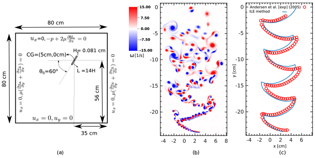
(a) Schematic diagram of the computational domain and boundary conditions for freely falling fluttering plate (Sec. 4.3.1). (b) Vorticity field at t = 2.68 s. (c) Comparison of the trajectory of the center of mass using the present ILE method (solid blue line) to the experimental data of Andersen et al. [97] (red circles).
The domain is discretized using N = 6 nested grid levels, with coarse grid spacing hcoarsest = Ly/16 = 5 cm and refinement ratio r = 4 between levels, leading to hfinest = 0.00488 cm. Using Mfac = 1.8, this leads to the thickness of the plate being discretized by approximately 10 linear elements. A constant time step size of Δt = 0.01 ms is used, and the penalty spring constant is κ = 7.45 × 10⁵ g · cm−2 · s−2. Figs. 13(b) and 13(c) shows the overall dynamics of the plate during its fluttering free fall. Fig. 13(b) shows the vortex structure over the course of the simulation. Periodic fluttering motion is clearly observed. Fig. 13(c) shows the trajectory of the center of mass along with the experimental data of Andersen et al. [97]. Overall, our numerical results are in good agreement with the experimental data for the gliding motion of the plate from side to side as it flutters in its free fall. Discrepancies around turning points can be, in part, attributed to the interaction of the complex vortex dynamics with sharp corners of the rectangular object. There are also uncertain differences in the simulation and experimental operating conditions that could explain these differences. Future studies should further investigate the accuracy of the present IIM coupling strategy for objects with sharp corners, including assessing grid sensitivity.
Fig. 14 shows close-up views of the fluttering plate at six different time points. With a low angle of attack, the plate glides from a turning point on one side to reach a new turning point on the opposite side. Towards the end of its glide and before it changes direction, there is a sharp increase in the magnitude of the angular velocity. Because of the sharp edge of the structure, the flow separates on the lower surface (Fig. 14(c)) and shortly thereafter flow separation also occurs on the upper surface as well (Fig. 14(d)). As the plate pitches upward, it begins to glide in the opposite direction, and this process repeats itself in a periodic manner. The interaction of vortices in the locations where the plate reverses direction creates a complex pattern of vortices, as shown in the figure. Fig. 15 shows the time history of the horizontal and vertical velocity components as well as the angular velocity along with a comparison to the experimental results [97]. Overall, there is very good agreement between the two results despite the complex dynamics. Although the algorithm is able to correctly predict the periodic dynamics, small deviations from measured data are observed particularly around troughs and crests of both translational and angular velocity plots. We speculate that these deviations could potentially be due to sensitivity of the results to the complex interaction of the shed vortices with the sharp corners, or possibly other uncertainties that are not accounted for in the comparison.
Figure 14:
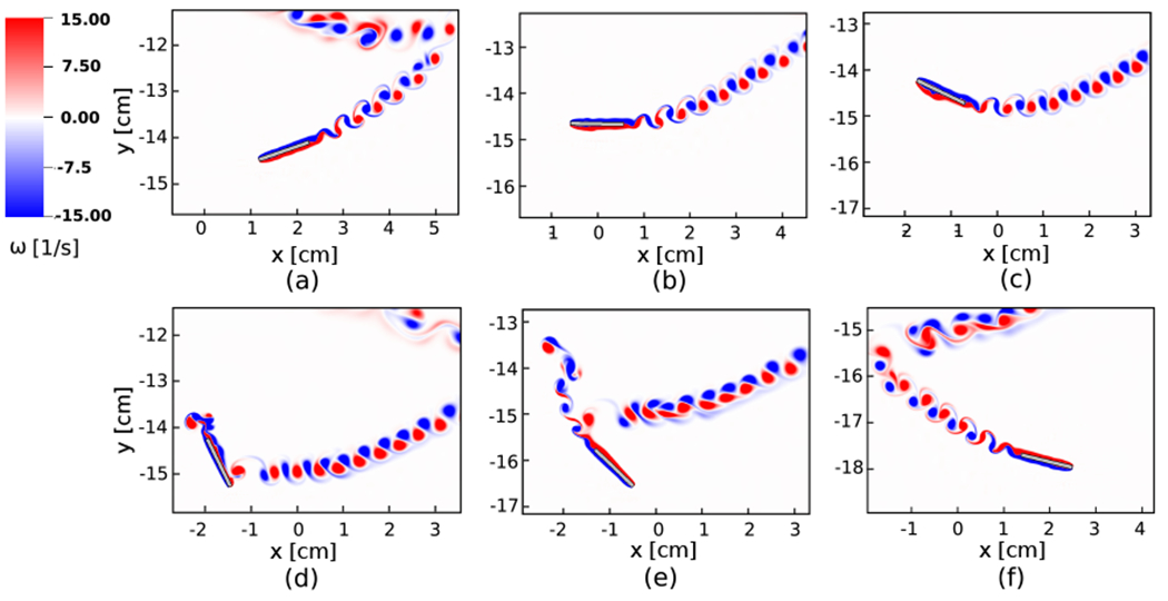
Enlarged views of the vorticity field for the fluttering plate (see Fig. 13(b)) at times (a) t = 1.40 s, (b) t = 1.45 s, (c) t = 1.50 s, (d) t = 1.59 s, (e) t = 1.65 s, and (f) t = 1.74 s.
Figure 15:
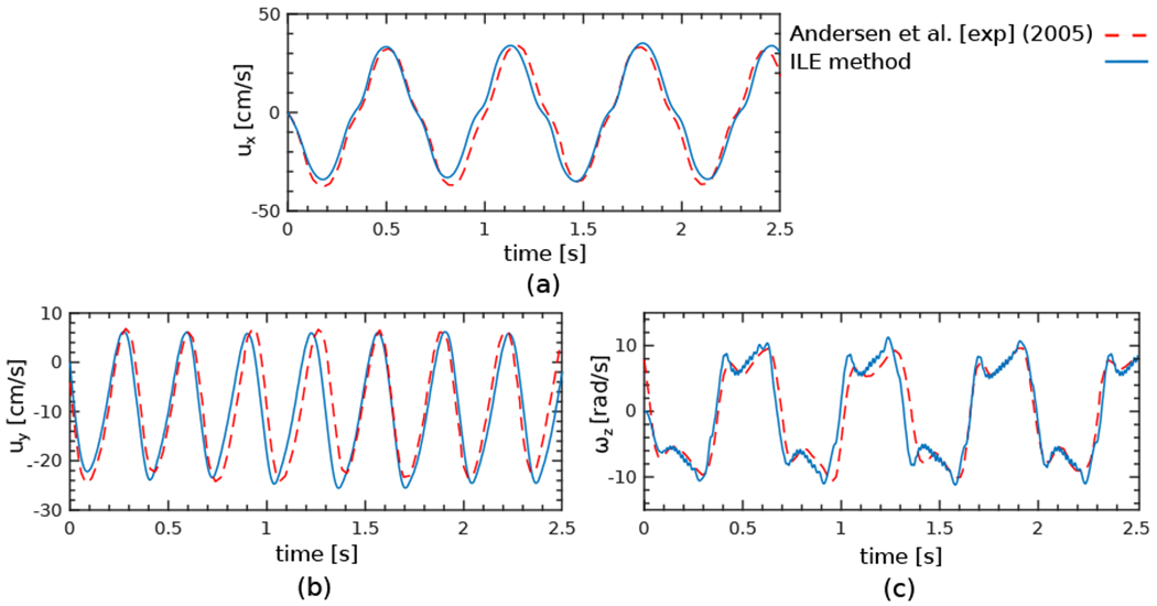
Comparison of the (a) horizontal velocity, (b) vertical velocity, and (c) angular velocity between the ILE method (solid blue lines) and the experimental data of Andersen et al. [97] (dashed red lines) for the fluttering plate (Sec. 4.3.1).
4.3.2. Tumbling motion
For the tumbling case, the plate thickness is kept fixed at H = 8.1 × 10⁻² cm, but the width-to-thickness ratio is changed to Λ = L/H = 8. The initial location and angle of attack are (x0, y0) = (−20 cm, 0 cm) and θ0 = −45°, respectively. Note that because of the different width of the plate in this example, the Reynolds number is Re = 837. The penalty spring constant is κ = 5.5 × 10⁵ g · cm−2 · s−2. The remaining simulation parameters, including the computational domain extent and size, spatial resolution, time step size, boundary conditions, and fluid properties, are identical to the fluttering case; see also the schematic in Fig. 16. Fig. 17 shows the overall dynamics of the tumbling plate. As shown in Fig. 17(a), the complex vortex structure of the tumbling plate is well resolved by the simulation. After the plate is released, it begins a gliding motion. Shortly after, it pitches upward, similar to the fluttering case. Because of the large angular momentum, however, at the turning point the plate rotates more than 90° clockwise. This large rotation, creates a large restoring moment that causes the plate to rotate slightly counter-clockwise and then continue falling, with an inclination to the right side. The plate travels a path towards the bottom-right corner of the computational domain by a sequence of descending and accelerating motions. At the turning points, the plate undergoes a full 360° tumbling rotation, such that the lower surface during the gliding re-configures as upward facing. Fig. 17(b) compares the vortex structure and trajectory of the tumbling plate to experimental measurements [97]. As in the fluttering case, the results are in very good agreement with the experimental data, and the trajectory of the plate agrees very well for the portion of the trajectory where experimental data are available. Fig. 18 shows enlarged views of the vorticity field at different times. Flow separation on the lower side of the plate is clearly observed in Fig. 18(c). This is followed by separation of the flow on the opposite side as the plate rotates (Fig. 18(d)). The gliding and diving towards the bottom left resumes at the end of each tumbling motion, as seen in Fig. 18(f).
Figure 16:
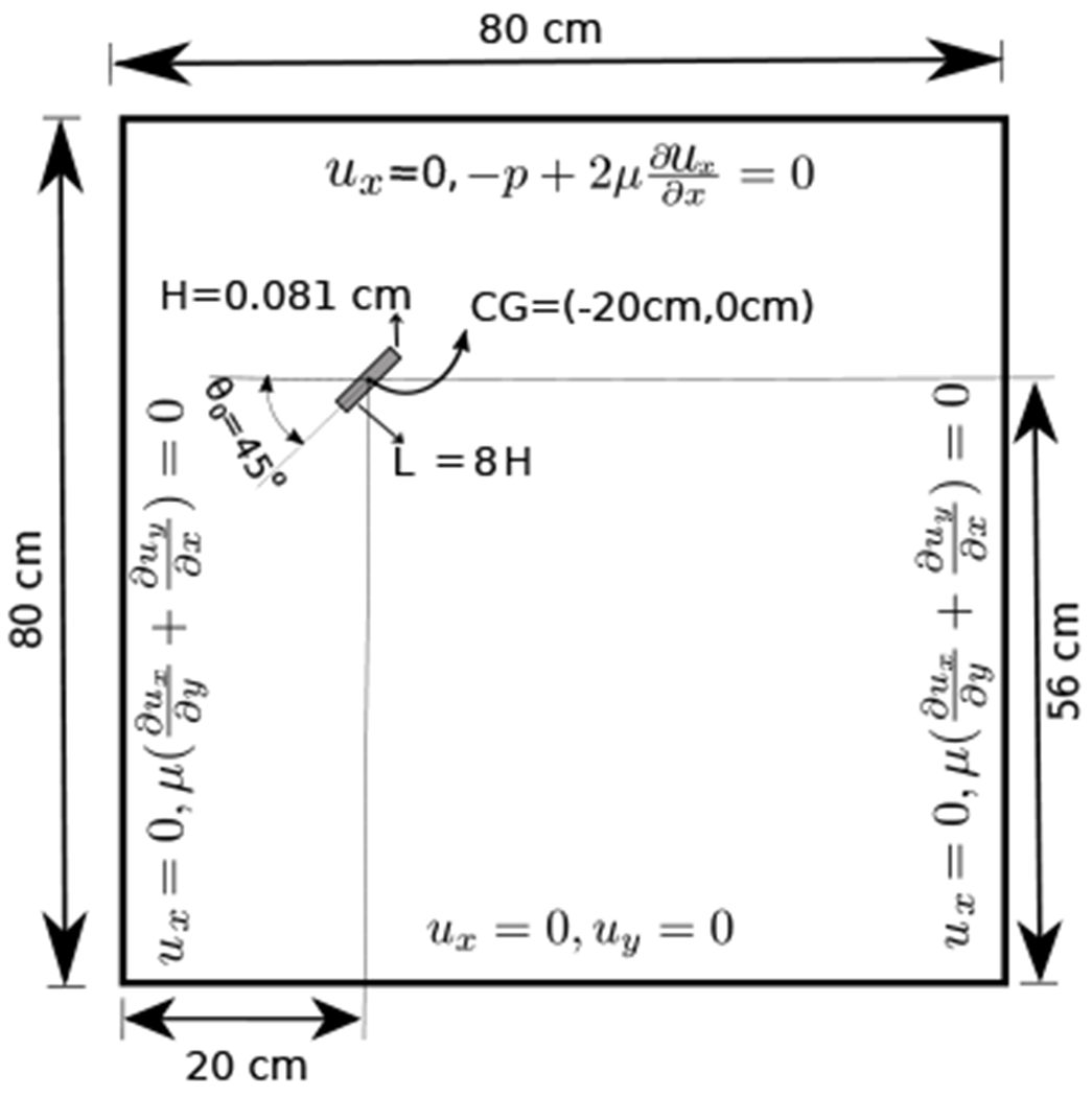
Schematic diagram of the computational domain and boundary conditions for freely falling tumbling plate (Sec. 4.3.2).
Figure 17:
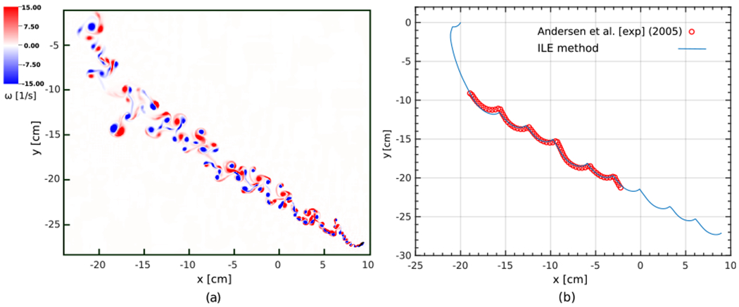
Freely falling rectangular plate undergoing tumbling motion at Re = 837. (a) Vorticity field at time t = 2.06 s. (b) Comparison of the trajectory of the center of mass using the present ILE method (solid blue line) to the experimental data of Andersen et. al. [97].
Figure 18:
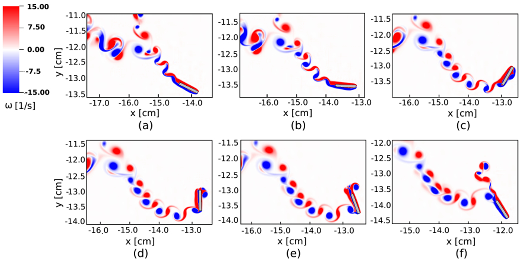
Enlarged views of the vorticity field for the tumbling plate (see Fig. 17(a)) at times (a) t = 0.64 s, (b) t = 0.66 s, (c) t = 0.70 s, (d) t = 0.72 s, (e) t = 0.74 s, and (f) t = 0.78 s.
Fig. 19 shows the time history of translational and rotational velocities. Unlike the fluttering case, in which the vertical velocity appeared to have twice as larger frequency than the other two velocities, here the number of periods demonstrates that approximately the same frequency is observed among all velocities. In addition, the significantly larger angular velocity in this case compared to the fluttering case in Fig. 15 indicates faster rotation near the turning points. The average horizontal and vertical velocity components and the average angular velocity obtained from three full cycles of the present simulation are found to be , , and . For comparison, the experimental measurements of Andersen et al. [97] for the same average velocities are , , and . The relative discrepancies in these quantities are 0.19%, 1.57%, and 9.93%, respectively.
Figure 19:
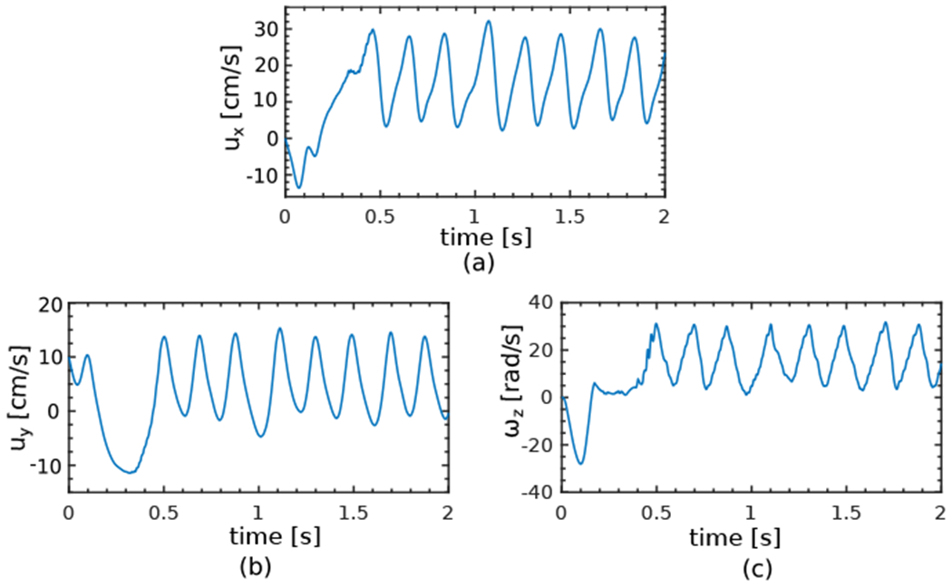
Time history of the (a) horizontal velocity, (b) vertical velocity, and (c) angular velocity for the tumbling plate (Sec. 4.3.2).
4.4. Free falling of a dense sphere
This section investigates the dynamics of a freely falling steel bead in water using an unconstrained rigid-body structure model. This problem follows the experimental setup of Mordant and Pinton [98]. The density of the steel bead is ρs = 7.85 g · cm−3, and the diameter is D = 0.1 cm. The Reynolds number is , and a terminal velocity of is reported in the original work. With a fluid density of ρf = 997 g · cm−3, this results in a dynamic viscosity of μf = 8.88 × 10⁻³ g · cm−1 · s−1. The computational domain is Ω = [−16D, 16D] × [−448 D, 64 D] × [−16 D, 16 D], a rectangular cuboid of size Lx × Ly × Lz = 32D × 512D × 32D; see Fig. 20(a) for a schematic of the problem setup. Zero normal traction and tangential velocity conditions are imposed at the top boundary. Along the peripheral walls zero normal velocity and tangential traction are imposed. The no-slip condition is imposed at the bottom boundary. The domain is discretized using N = 3 nested grid levels, with coarse grid spacing hcoarsest = Lx/64 = 0.05 cm and refinement ratio r = 4 between levels, leading to hfinest = 0.003125 cm. The volumetric mesh of the sphere consists of hexahedral elements leading to a surface mesh composed of bilinear quadrilateral elements with Mfac = 2. A fixed time step size of Δt = 0.01 ms is used, and the penalty spring constant is κ = 5 × 10⁵ g · cm−2 · s−2. The center of the sphere is initially positioned at the origin and released with zero initial translational and angular velocities. Fig. 20(b) shows the time history of the vertical velocity. After being released, the steel bead starts to accelerate until reaching its terminal velocity. The acceleration of the bead is in good agreement with the experimental data of Mordant and Pinton [98], and the terminal velocity is also in excellent agreement with the experimental measurement. Fig. 20(c)–(e) show isosurfaces of the Q-criterion [121] to visualize the vortex dynamics. Note that there is no constraint in the motion of the sphere, and that all of the degrees of freedom including the rotational ones are included in the solution. Shortly after the sphere reaches its terminal velocity , the flow behind the sphere becomes irregular due to the moderately large Reynolds number. Although small lateral movements are observed in the simulation with the deviation of center of mass reaching to about 0.25D = 8hfinest, no consistent pattern of “zig-zagging” motion is apparent. Fig. 20 also compares our results to two other numerical studies [115, 116].
Figure 20:
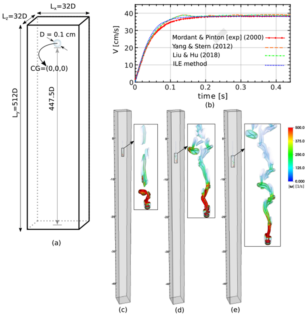
(a) A schematic of the initial setup for the freely falling steel bead (Sec. 4.4) with ρs/ρf = 7.8. Note that lengths in the schematic are not to scale. (b) Vertical velocity of the freely falling steel bead, including a comparison to the experimental data of Mordant and Pinton [98] and the numerical results of Yang and Stern [115] and Liu and Hu [116]. (c)–(e) Instantaneous wake vortex patterns illustrated as isosurfaces of the Q criterion at the time t = 0.132 s, t = 0.146 s, and t = 0.179 s, respectively.
4.5. Free fall of a sphere with near-unity density ratio
This section explores the performance of the ILE methodology with respect to two challenging aspects of FSI: the influence of the wall and the ability of the method to handle near-unity density ratios in a fully unconstrained rigid-body motion. This case is based on the experimental data reported by ten Cate et al. [99] of a sphere settling in a confined flow chamber. The sphere has diameter D = 1.5 cm and density ρs = 1.120 g · cm−3, which is close to that of the surrounding fluid; see Table 4. The Reynolds number is , in which the terminal velocity is taken to be the settling velocity in an infinite domain. Two different cases with Reynolds numbers of Re = 1.5 and Re = 31.9 are considered, which are achieved in the experiments by varying the density and viscosity of the fluid. The computational domain is Ω = [−5 cm, 5 cm] × [−12 cm, 4 cm] × [−5 cm, 5 cm], a rectangular cuboid of size Lx × Ly × Lz = 10 cm × 16 cm × 10 cm. The sphere is initially positioned in the x-z mid-plane and towards the top of the box at a height of 12 cm, measured from the bottom of the sphere to the bottom of the box; see Fig. 21(a). Zero normal traction and tangential velocity conditions are applied at the top boundary while no-slip condition is imposed at all other boundaries.
Table 4:
Parameters for freely falling sphere with near-unity density ratio (Sec. 4.5)
Figure 21:
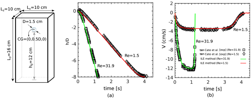
(a) A schematic of the initial setup of a single sphere in a small flow chamber with near unity solid-fluid density ratio (Sec. 4.5). (b) Time history of the vertical position and (c) vertical sedimentation velocity.
The domain is discretized using N = 3 nested grid levels, with coarse grid spacing hcoarsest = Lx/32 = 0.3125 cm and refinement ratio r = 2 between levels, leading to hfinest = 0.078125 cm. The volumetric mesh of the sphere consists of hexahedral elements leading to a surface mesh composed of bilinear quadrilateral elements with Mfac = 2. A fixed time step size of Δt = 0.5 ms is used, and the penalty spring constant is κ = 5 × 10⁴ g · cm−2 · s−2. Because of the confinement effect of the walls, we expect the settling of the sphere to be different from a free falling sphere in an infinite medium. Upon release, the particle accelerates until reaching its terminal velocity, which occurs quickly in the lower Reynolds number case. The sphere then starts to decelerate as it approaches to the bottom the flow chamber. Fig. 21 panels (b)–(c) show the time histories of the non-dimensional vertical gap between the sphere and bottom wall (h/D) and the vertical velocity of the sphere () for both cases. The method yields excellent agreement with the experimental measurements of ten Cate et al. [99] for both the gap size over time and the terminal velocity. Specifically, the present method captures the dynamics of the sphere while also remaining stable even as the sphere reaches the bottom of the box. For the lower Reynolds number case, the sphere has more time to travel through the box because of its lower speed, and this results in a larger flat region, when the sphere experiences a nearly constant downward velocity, before it starts to decelerate as it approaches the bottom wall. Indeed, at Re = 1.5, we observe stable sedimentary motion of the sphere in the simulation even past the latest time reported in the experiment. At Re = 31.9, the sphere does not experience an extended period of time at terminal-like velocity as it quickly reaches the bottom of the box. The simulation is also stable for this case even after the sphere impacts the bottom; see Fig. 21(b).
4.6. Freely rising sphere
This section considers a rising sphere using a fully unconstrained rigid-body structural model. Such problems can pose substantial challenges to FSI algorithms using weak coupling schemes, which can become unstable [116]. Experimental results of Horowitz and Williamson [100] are used as a benchmark to validate the dynamics generated by our numerical method. We consider a challenging case in which the parameters are chosen such that the sphere oscillates periodically and vigorously in a “zig-zag” trajectory within a tight vertical plane. The sphere has diameter D = 1.3 cm and mass ratio m* = 0.11. The experiments are at Re = ρfU D/μf = 450. To match the experimental Reynolds number, the dynamic viscosity is μf = 0.125 g · (cm·s)−1. The computational domain is Ω = [−16 D, 16 D] × [−112 D, 16D] × [−16 D, 16 D]; see the schematic in Fig. 22. The domain is discretized using N = 3 nested grid levels, with coarse grid spacing hcoarsest = Lx/64 = 0.65 cm and refinement ratio r = 4 between levels, leading to hfinest ≈ 0.04 cm. The volumetric mesh of the sphere consists of hexahedral elements leading to a surface mesh composed of bilinear quadrilateral elements with Mfac = 2. The center of the sphere is initially positioned at (0, −96 D, 0) and is released with zero initial translational and angular velocity. Zero normal traction and tangential velocity conditions are imposed at the top boundary. The no-slip condition is imposed at the bottom boundary. Along the peripheral walls zero normal velocity and tangential traction are imposed. The no-slip condition is imposed at the bottom boundary. A fixed time step size of Δt = 0.01 ms is used, and the penalty spring constant is κ = 5.2 × 10⁵ g · (cm · s)−2.
Figure 22:
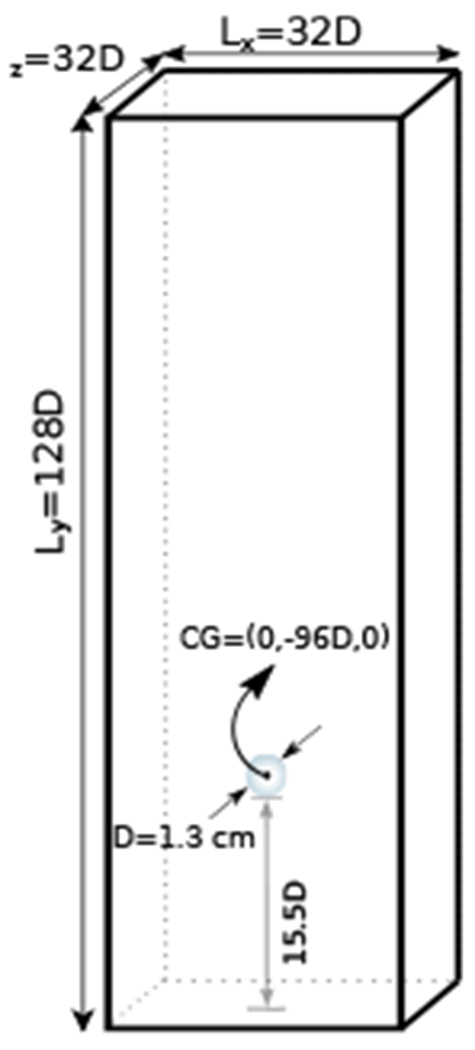
Schematic diagram of the computational domain for freely rising sphere (Sec. 4.6).
Fig. 23 demonstrates that the sphere motion is approximately planar, and captures the periodic zig-zag trajectory observed experimentally. We emphasize that in our simulation, no constraints are imposed on the motion of the sphere. Specifically we do not impose either planar motion or the zig-zag trajectory. According to Horowitz and Williamson [100], the periodic motion of the sphere at this particular density ratio resembles the dynamics at much higher Reynolds number and is always confined to a plane. The simulation results predict the same kind of in-plane motion as observed in the experiment. As the sphere goes through the zig-zag motion it creates a complex but organized wake pattern with vortex rings forming at the turning points. The numerical simulation clearly captures the vortices behind the sphere. Further, there is generally excellent agreement with the trajectory obtained from the experiment.
Figure 23:
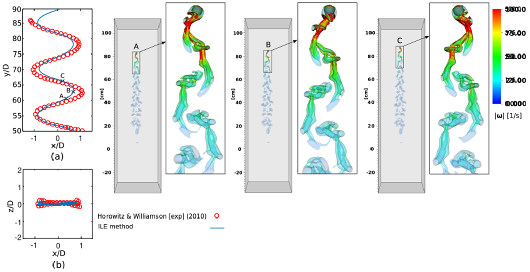
Trajectory of the center of mass for the rising sphere (Sec. 4.6) in the (a) x-y and (b) x-z planes along with the experimental data of Horowitz and Williamson [100]. The vortex wake structure for the rising sphere at locations A, B, and C shown on the x-y plane trajectory. Simulation parameters include Re = 450, m* = 0.11, and D = 1.3 cm.
4.7. Bileaflet mechanical heart valve at physiological conditions
Bileaflet mechanical heart valves remain commonly used in heart valve replacement because of their durability. In this section, we consider the simulation of fluid flow through a geometrically realistic model of a 25 mm St Jude Medical Regent™ bileaflet mechanical heart valve in the aortic test section of an experimental pulse duplicator platform [122, 123]. These systems are used in academia, industry, and regulatory agencies to assess the performance of prosthetic heart valves. This simulation aims to demonstrate the ability of the present approach in modeling a realistically complex problem that involves multiple moving and stationary parts, including the small-scale feature of the hinge geometry. These parts come in close contact with each other and undergo substantial pressure loading when closed. In particular, we use experimental pressure and flow data obtained from a real pulse duplicator to establish realistic boundary models for the FSI model. These boundary models are calibrated in isolation from the rest of the system in that the motion of the leaflets, including the timing of valve opening and closing, is not prescribed and the simulated pressures, flow rates, and leaflet kinematics all emerge from integrating these three model components. The experiments conducted to calibrate the model used saline as a test fluid, which we model as a Newtonian fluid with uniform density ρf = 1.0 g · cm−3 and uniform dynamic viscosity μ = 1.0 cP. The computational domain is Ω = [0, Lx] × [0, Ly] × [0, Lz] a rectangular cuboid of size Lx × Ly × Lz = 7.07 cm × 10.1 cm × 7.07 cm. Fig. 24 shows the geometrically detailed three-dimensional model including the valve leaflets and the aortic test section of the pulse duplicator, the computational mesh, and relevant boundary conditions. The Eulerian domain is discretized using N = 4 nested grid levels, with coarse grid spacing hcoarsest = Lx/34 ≈ 0.208 cm and refinement ratio r = 2 between levels, leading to hfinest ≈ 0.026 cm. The volumetric mesh of each valve leaflet consists of hexahedral elements leading to a surface representation composed of bilinear quadrilateral elements with Mfac ≈ 2. The test section is a stationary surface described by bilinear quadrilateral elements with Mfac = 3. The thickness of the valve leaflets is about 0.07 cm and the density is ρs = 1.8 g · cm−3. The gap distance between the two valves is measured to be 0.0275 cm. The penalty spring constant associated with the valves is set to κ = 5 × 10⁶ g · (cm · s)−2. The motion of each leaflet is constrained to consist only of rotation about predefined hinge axes. A restoring spring-damper tortional force is used to keep the right valve leaflet restricted in its rotation between θmin = 24° and θmin = 82°. The same rule is applied to keep the left valve leaflet restricted with mirrored angle. The test section is kept stationary by means of spring-type penalty forces with κ = 1.5 × 10⁶ g · cm−2 · s−2. A fixed time step size of Δt = 2 μs is used for the simulation. Three-element Windkessel models establish downstream loading conditions and the upstream driving conditions for the aortic test section. A combination of normal traction and zero tangential velocity boundary conditions are used at the inlet and outlet to couple the reduced-order models to the detailed description of the flow within the test section. The values of the resistances and compliance for the upstream model are CVIA = 0.1 mL · mmHg−1 and R1 = R2 = 0.15 mmHg · mL−1 · s. The values at the downstream model are Rc = 0.0077 mmHg · mL−1 · s , Rp = 1.226 mmHg · mL−1 · s, and C = 1.039 mL · mmHg−1; see Griffith et al. [124] and Lee et al. [125] for further discussion on the specification and parameterization of the Windkessel models. Solid wall boundary conditions are imposed on the remaining boundaries of the computational domain.
Figure 24:
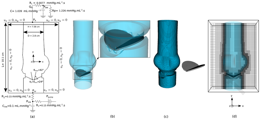
Model setup of the bileaflet mechanical heart valve (Sec. 4.7). (a) Schematic cross-section view of the aortic test section on the x-y mid-plane plane showing the dimensions and boundary conditions. A three-element Windkessel model is used at the downstream and upstream of the test section while all other boundaries are set to solid wall boundary. (b) Assembly of the aortic test section including the bileaflet valve and their position around the hinges. (c) Computational mesh of the aortic test section and the valve. (d) The computational domain in which the aortic test section is embedded in. The block-structured adaptively refined Cartesian grid is shown on the x-y mid-plane.
Fig. 25 shows the velocity magnitudes on the plane bisecting the valves at different time points within the simulated cardiac cycle. At early times when the valves are closed there exists a large pressure difference across the test section that forces jets of the fluid to escape from small gaps around the valves with velocity magnitude that reaches about 450 cm · s−1 at its peak. These hinge gap flows have been well characterized for bileaflet mechanical valves result from gaps between the leaflets and the housing and around the hinge areas in a fully closed position [126, 127, 123]. These flows create a complex vortical interaction later in the diastole phase of the cardiac cycle, when the valve is closed and supporting a physiological pressure load. Von Karman like vortex shedding clearly occurs during the systolic phase, when the valves are fully open. Many prior numerical simulations of mechanical heart valve models have been restricted to imposing either experimental flow rates, or flow dynamics under prescribed leaflet motion. Because the flow rate is not imposed in the present model, and because the time-dependent configuration of the valve determines the resistance of the aortic test section, this simulation demonstrates a non-trivial test of the numerical method.
Figure 25:
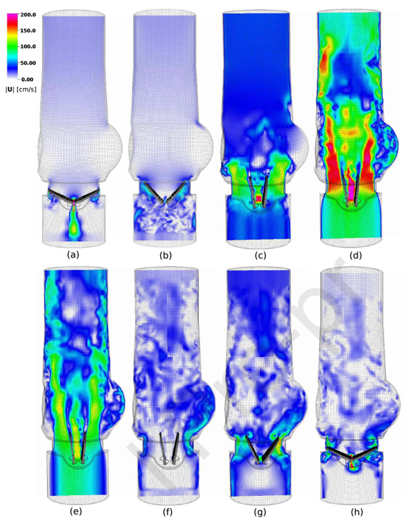
Velocity magnitudes of bileaflet mechanical heart valve (Sec. 4.7) on the x-y mid-plane bisecting the valve, given at times (a) t = 0.0225 s, (b) t = 0.1050 s, (c) t = 0.1275 s, (d) t = 0.1875 s, (e) t = 0.2925 s, (f) t = 0.3550 s, (g) t = 0.3675 s, and (h) t = 0.375 s.
4.8. Transport of rigid blood clots in the inferior vena cava at exercise flow conditions
As a demonstration of the method’s capability in modeling the motion of unconstrainted three-dimensional objects in a complex geometry, we simulate transport of rigid blood clots through the inferior vena cava (IVC) at a high flow rate of 100 cm3/s, which corresponds to exercise flow conditions with a maximum Reynolds number of about Re = 1500. The IVC is a large vein that transports deoxygenated blood from lower extremities of the body back to the right atrium of the heart. The geometry of the IVC shown in Fig. 26 is a modified version of the patient-averaged model by Rahbar et al. [128] that has been recently used in studies of the hemodynamics [129, 130, 68]. The infrarenal IVC downstream of the iliac bifurcation has average hydraulic diameter Dh = 2.8 cm. The density of the fluid is ρf = 1.817 g · cm−3, and the viscosity is μf = 5.487 × 10⁻² g/cm s. Steady fully-developed parabolic velocity boundary conditions are imposed at the upstream inlets of the iliac veins. The two inlets are circular with diameter D = 2.44 cm, which then transitions to an elliptical shape a short distance downstream. The surface of the IVC is described using bilinear quadrilateral elements with Mfac ≈ 2. The IVC is embedded in a rectangular computational domain of size Ω = Lx × Ly × Lz = 50 cm × 25 cm × 50 cm. The Eulerian domain is discretized using a three-level locally refined grid with a refinement ratio of four between the grid levels, resulting in a grid spacing of on the coarsest level and on the finest grid level. At the outlet, the normal traction and tangential velocities are set to zero. Solid-wall boundary conditions are imposed along the remainder of ∂Ω. Once steady state condition of the flow has been reached at t = 5.0 s, two neutrally buoyant rigid spherical clots (ρs = ρf) of diameter Di = 1 cm are released from positions close to the two inlets. The volumetric mesh of each sphere consists of hexahedral elements leading to a surface mesh composed of bilinear quadrilateral elements with Mfac = 2. A fixed time step size of Δt = 0.1 ms is used. The penalty spring constant associated with both the IVC and the clots is κ = 1.05 × 10⁵ g · (cm · s)−2. Fig. 27 shows the transport of rigid blood clots under the unconstrained rigid-body model. A few streamlines are also plotted to show the direction of the flow. Despite the moderately high Reynolds number of the flow and the complex pathway, the clots migrate towards the outlet through the iliac veins while being confined within the IVC structure. After passing the confluence of the veins, the clots come in very close contact with each other in a more complex fluid environment where we expect the emergence of a pair of counter-rotating vortices after the confluence as a result of the two streams from iliac veins merging together. The clots continue migrating towards the outlet with a higher speed where towards the end, the clot from the right ilict vein tends to get ahead. This can be attributed to the complex nature of the flow in the region above the confluence.
Figure 26:
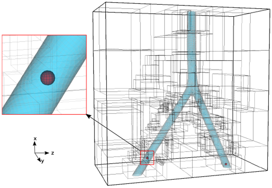
Computational mesh of the patient-averaged model of the inferior vena cava (IVC), the locally refined Cartesian grid and rigid spherical clots insde IVC (Sec. 4.8).
Figure 27:
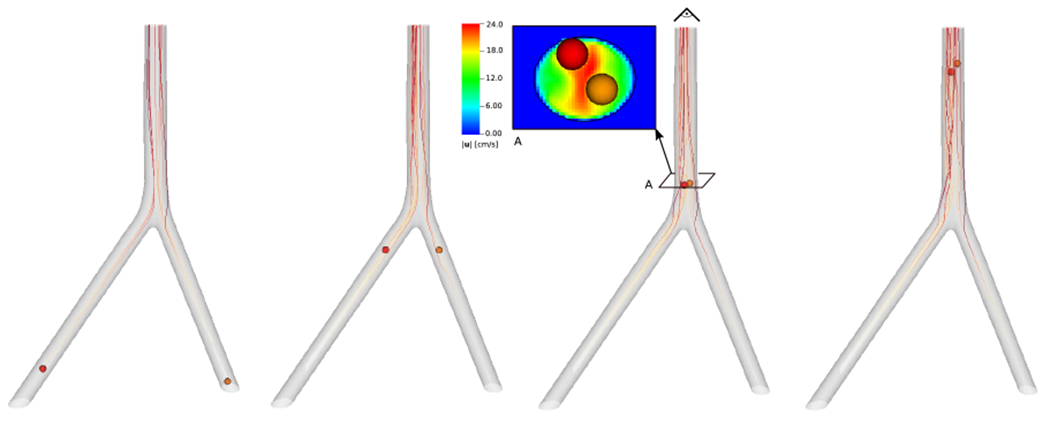
Transport of spherical clots inside IVC under exercise condition. The snapshots are given from left to right at times t = 5.0 s, t = 6.75 s, t = 7.50 s, and t = 8.50 s. A top view of velocity magnitudes are shown for cross section A.
5. Discussion and Conclusions
This work has introduced a numerical approach to simulating fluid-structure interaction that we refer to as an immersed Lagrangian-Eulerian (ILE) method. Results from applying this ILE method to benchmark problems of rigid body fluid-structure interaction with increasing difficulty were presented. In addition, we also show representative results from applications of this methodology to two biomedical FSI models: a bileaflet mechanical heart valve under physiological conditions in a model of the aortic test section of a commercial pulse duplicator, and transport of rigid blood clots inside a patient-averaged model of the inferior vena cava under exercise conditions. Unlike existing partitioned methods for FSI, the ILE formulation uses an immersed approach to couple the fluid and structure subdomains and thereby reduces or even eliminates the need for grid regeneration during dynamic simulations. In this formulation, it is crucial to deploy a coupling approach that provides the forces from only the exterior physical fluid region, and in this work, we use a coupling scheme based on the immersed interface method, which enables us to evaluate these external fluid tractions along the fluid-structure interface. At least in principle, however, the present method could be used with any coupling strategy that determines the net exterior fluid force acting on the fluid-solid interface. Notice that this excludes conventional immersed boundary formulations using regularized delta functions because such formulations provide the total force from both the the exterior (physical) and interior (nonphysical) fluid regions. We remark that the jump conditions associated with the singular interfacial force are projected onto continuous Lagrangian basis functions, as described previously [68]. This requires the solution of linear systems of equations. We emphasize, however, that these solves involve only surface degrees of freedom, and thus are an order of magnitude smaller than the volumetric fluid equations that also are solved in each time step. In addition, the linear systems involve discrete L2 projection equations that can be solved optimally using simple iterative methods (e.g. by a Krylov method preconditioned with a diagonal or lumped mass matrix). Overall, the dominant cost of each time step is in solving the incompressible Navier-Stokes equations, and the remaining computations are relatively inexpensive. A strength of the current approach is that it enables the use of fast Cartesian grid solvers for the incompressible Navier-Stokes equations.
The FSI coupling strategy allows fluid and solid subproblems to be solved in a partitioned manner as independent, nonconforming discretizations that are coupled through interface conditions. In our discretization approach, there exist two Lagrangian representations of the fluid-solid interface, including the boundary of the volumetric mesh used in solving the equations of rigid body dynamics and a surface mesh that moves with the local fluid velocity. These two representations are constrained to move together by a Lagrange multiplier surface force. Exactly imposing the constraint would require the solution of a saddle-point system that couples the Eulerian and Lagrangian variables, but we develop a practical numerical scheme that avoids the complex numerical linear algebra associated with such systems by relaxing this constraint using a penalty formulation. In the penalty formulation, the surface mesh moves according to the local fluid velocity but exerts force locally to the fluid as a weak imposition of the no-slip condition. Discrepancies in the positions of the boundary representations can be controlled by increasing the penalty parameter. In the present work, the maximum relative displacement is always less than 0.1 of the Cartesian grid spacing.
An attractive feature of the present ILE method is that, at least for the specific examples considered herein, it enables the use of a simple Dirichlet-Neumann coupling scheme [84, 93, 95] without requiring either strong coupling or subiterations to maintain stability. In particular, the motion of the solid mesh is driven by the exterior fluid traction, and the motion of the solid mesh drives the motion of the fluid-structure interface representation used to impose the no-slip condition. Although we do not theoretically determine whether the ILE formulation suffers from added mass-related instabilities, the computational tests reported herein suggest that it can stabily treat a broad range of density ratios, including structures that are less dense than the fluid, more dense than the fluid, and neutrally buoyant. This is demonstrated for multiple benchmark problems. For instance, in a 2-DOF model of the oscillation of a cylinder under vortex induced vibration, we obtain stable results for mass ratios up to 40 times smaller than smallest value reported in recent prior work [113]. In the literature, added mass instabilities are typically ascribed to the treatment of fluid regions that become “uncovered” by the structure as it moves through the computational domain. These include ALE approaches [92, 91, 131] and other sharp interface methods [19, 132]. Specialized approaches can be needed with these methods to avoid pressure fluctuations for cases involving low and near-equal density ratios. Although the total mass and momentum of the fluid are conserved, there are local changes in the fluid mass and momentum in the regions that are both “covered” and “uncovered” by the moving structure. Evidently, these localized changes in the fluid mass and momentum can induce temporal discontinuities in the velocity. In the IIM approach introduced by Li and Lai [29], the fluid equations are solved on the entire computational domain, including region occupied by the structure, similar to diffuse-interface formulations like those used in Peskin’s IB method. Using the IIM terminology, the continuity of the velocity field across the fluid-structure interface implies ⟦u(x, t)⟧ = 0. A direct consequence of this condition for the immersed interface approach is that the jump in the material derivative of the velocity is also zero, i.e. . This means that fluid trajectories do not cross the moving interface and fluid locations that are “uncovered” by the motion of the structure automatically possess velocities that are consistent with the equations of motion. In contrast, for methods in which the fluid domain only exists on one side of the interface, the temporal jump associated with the material derivative of the velocity may be non-zero going from one time step to the next as a fixed Eulerian grid point may switch sides between consecutive time steps. This temporal discontinuity in the fluid acceleration could be important as added mass instabilities arise when the inertial effect due to fluid forces are dominant. This could result in a fluid pressure that is out of phase with the fluid acceleration. Although this has yet to be proved rigorously, we hypothesize that the apparent robustness of the method to artificial added mass instabilities results from its consistent treatment of the momentum of the fluid near the fluid-structure interface. Added mass-type instabilities might also be suppressed by our use of rigid-body structure models, which are driven by the net fluid force acting on the immersed structure rather than by pointwise forces. Rigorous stability analyses and analytical investigations of the methodology similar to those recently developed for overset grid methods [84, 83, 133, 94] may reveal stability criteria or clarify the absence of added mass-type instabilities in this formulation. Finally, we note that although the formulation presented here assumes the use of a rigid body structural model, it is natural to extend this approach to immersed elastic bodies.
Acknowledgements
We acknowledge research support through NIH Awards HL117063 and HL143336, NSF Awards DMS 1664645, CBET 175193, OAC 1450327, OAC 1652541, and OAC 1931516, and the U.S. FDA Center for Devices and Radiological Health (CDRH) Critical Path program. This research was supported in part by an appointment to the Research Participation Program at the U.S. FDA administered by the Oak Ridge Institute for Science and Education through an interagency agreement between the U.S. Department of Energy and FDA. A.P.S.B also acknowledges support from NSF award OAC 1931368. Computations were performed using facilities provided by University of North Carolina at Chapel Hill through the Research Computing division of UNC Information Technology Services and the high-performance computing clusters at the U.S. FDA. The findings and conclusions in this article have not been formally disseminated by the FDA and should not be construed to represent any agency determination or policy. The mention of commercial products, their sources, or their use in connection with material reported herein is not to be construed as either an actual or implied endorsement of such products by the Department of Health and Human Services. We also thank Kenneth Aycock, Saad Qadeer, Jianhua Qin, and Simone Rossi for their constructive comments to improve the manuscript.
Footnotes
Publisher's Disclaimer: This is a PDF file of an unedited manuscript that has been accepted for publication. As a service to our customers we are providing this early version of the manuscript. The manuscript will undergo copyediting, typesetting, and review of the resulting proof before it is published in its final form. Please note that during the production process errors may be discovered which could affect the content, and all legal disclaimers that apply to the journal pertain.
Declaration of interests
The authors declare that they have no known competing financial interests or personal relationships that could have appeared to influence the work reported in this paper.
References
- [1].Takashi N, Hughes TJ, An arbitrary Lagrangian–Eulerian finite element method for interaction of fluid and a rigid body, Computer Methods in Applied Mechanics and Engineering 95 (1) (1992) 115–138. [Google Scholar]
- [2].Hu HH, Patankar NA, Zhu M, Direct numerical simulations of fluid–solid systems using the arbitrary Lagrangian–Eulerian technique, Journal of Computational Physics 169 (2) (2001) 427–462. [Google Scholar]
- [3].Ahn HT, Kallinderis Y, Strongly coupled flow/structure interactions with a geometrically conservative ALE scheme on general hybrid meshes, Journal of Computational Physics 219 (2) (2006) 671–696. [Google Scholar]
- [4].Lee AH, Campbell RL, Craven BA, Hambric SA, Fluid–structure interaction simulation of vortex-induced vibration of a flexible hydrofoil, Journal of Vibration and Acoustics 139 (4) (2017) 041001. [Google Scholar]
- [5].Zahle F, Sørensen NN, Johansen J, Wind turbine rotor-tower interaction using an incompressible overset grid method, Wind Energy: An International Journal for Progress and Applications in Wind Power Conversion Technology 12 (6) (2009) 594–619. [Google Scholar]
- [6].Nakata T, Liu H, A fluid–structure interaction model of insect flight with flexible wings, Journal of Computational Physics 231 (4) (2012) 1822–1847. [Google Scholar]
- [7].Koblitz A, Lovett S, Nikiforakis N, Henshaw WD, Direct numerical simulation of particulate flows with an overset grid method, Journal of Computational Physics 343 (2017) 414–431. [Google Scholar]
- [8].Banks JW, Henshaw WD, Schwendeman DW, Tang Q, A stable partitioned FSI algorithm for rigid bodies and incompressible flow. Part II: General formulation, Journal of Computational Physics 343 (2017) 469–500. [Google Scholar]
- [9].Banks JW, Henshaw WD, Schwendeman DW, Deforming composite grids for solving fluid structure problems, Journal of Computational Physics 231 (9) (2012) 3518–3547. [Google Scholar]
- [10].Peskin CS, The immersed boundary method, Acta Numerica 11 (2002) 479–517. [Google Scholar]
- [11].Mittal R, Iaccarino G, Immersed boundary methods, Annual Review of Fluid Mechanics 37 (2005) 239–261. [Google Scholar]
- [12].Hou G, Wang J, Layton A, Numerical methods for fluid-structure interaction–a review, Communications in Computational Physics 12 (2) (2012) 337–377. [Google Scholar]
- [13].Griffith BE, Patankar NA, Immersed methods for fluid–structure interaction, Annual Review of Fluid Mechanics 52 (1) (2020) 421–448. [DOI] [PMC free article] [PubMed] [Google Scholar]
- [14].Fadlun E, Verzicco R, Orlandi P, Mohd-Yusof J, Combined immersed-boundary finite-difference methods for three-dimensional complex flow simulations, Journal of Computational Physics 161 (1) (2000) 35–60. [Google Scholar]
- [15].Udaykumar H, Mittal R, Rampunggoon P, Khanna A, A sharp interface Cartesian grid method for simulating flows with complex moving boundaries, Journal of Computational Physics 174 (1) (2001) 345–380. [Google Scholar]
- [16].Gilmanov A, Sotiropoulos F, A hybrid Cartesian/immersed boundary method for simulating flows with 3D, geometrically complex, moving bodies, Journal of Computational Physics 207 (2) (2005) 457–492. [Google Scholar]
- [17].Xu S, Wang ZJ, An immersed interface method for simulating the interaction of a fluid with moving boundaries, Journal of Computational Physics 216 (2) (2006) 454–493. [Google Scholar]
- [18].Mittal R, Dong H, Bozkurttas M, Najjar F, Vargas A, Von Loebbecke A, A versatile sharp interface immersed boundary method for incompressible flows with complex boundaries, Journal of Computational Physics 227 (10) (2008) 4825–4852. [DOI] [PMC free article] [PubMed] [Google Scholar]
- [19].Borazjani I, Ge L, Sotiropoulos F, Curvilinear immersed boundary method for simulating fluid structure interaction with complex 3D rigid bodies, Journal of Computational Physics 227 (16) (2008) 7587–7620. [DOI] [PMC free article] [PubMed] [Google Scholar]
- [20].Barad MF, Colella P, Schladow SG, An adaptive cut-cell method for environmental fluid mechanics, International Journal for Numerical Methods in Fluids 60 (5) (2009) 473–514. [Google Scholar]
- [21].Fai TG, Rycroft CH, Lubricated immersed boundary method in two dimensions, Journal of Computational Physics 356 (2018) 319–339. [Google Scholar]
- [22].Lai M-C, Peskin CS, An immersed boundary method with formal second-order accuracy and reduced numerical viscosity, Journal of Computational Physics 160 (2) (2000) 705–719. [Google Scholar]
- [23].Griffith BE, Peskin CS, On the order of accuracy of the immersed boundary method: Higher order convergence rates for sufficiently smooth problems, Journal of Computational Physics 208 (1) (2005) 75–105. [Google Scholar]
- [24].Roma AM, Peskin CS, Berger MJ, An adaptive version of the immersed boundary method, Journal of Computational Physics 153 (2) (1999) 509–534. [Google Scholar]
- [25].Griffith BE, Hornung RD, McQueen DM, Peskin CS, An adaptive, formally second order accurate version of the immersed boundary method, Journal of Computational Physics 223 (1) (2007) 10–49. [Google Scholar]
- [26].LeVeque RJ, Li Z, The immersed interface method for elliptic equations with discontinuous coefficients and singular sources, SIAM Journal on Numerical Analysis 31 (4) (1994) 1019–1044. [Google Scholar]
- [27].LeVeque RJ, Li Z, Immersed interface methods for Stokes flow with elastic boundaries or surface tension, SIAM Journal on Scientific Computing 18 (3) (1997) 709–735. [Google Scholar]
- [28].Li Z, Ito K, Lai M-C, An augmented approach for Stokes equations with a discontinuous viscosity and singular forces, Computers & Fluids 36 (3) (2007) 622–635. [Google Scholar]
- [29].Li Z, Lai M-C, The immersed interface method for the Navier–Stokes equations with singular forces, Journal of Computational Physics 171 (2) (2001) 822–842. [Google Scholar]
- [30].Lee L, LeVeque RJ, An immersed interface method for incompressible Navier–Stokes equations, SIAM Journal on Scientific Computing 25 (3) (2003) 832–856. [Google Scholar]
- [31].Le D-V, Khoo BC, Peraire J, An immersed interface method for viscous incompressible flows involving rigid and flexible boundaries, Journal of Computational Physics 220 (1) (2006) 109–138. [Google Scholar]
- [32].Hou TY, Li Z, Osher S, Zhao H, A hybrid method for moving interface problems with application to the Hele–Shaw flow, Journal of Computational Physics 134 (2) (1997) 236–252. [Google Scholar]
- [33].Sethian JA, Wiegmann A, Structural boundary design via level set and immersed interface methods, Journal of Computational Physics 163 (2) (2000) 489–528. [Google Scholar]
- [34].Xu J-J, Li Z, Lowengrub J, Zhao H, A level-set method for interfacial flows with surfactant, Journal of Computational Physics 212 (2) (2006) 590–616. [Google Scholar]
- [35].Xu S, Wang ZJ, Systematic derivation of jump conditions for the immersed interface method in three-dimensional flow simulation, SIAM Journal on Scientific Computing 27 (6) (2006) 1948–1980. [Google Scholar]
- [36].Lombard B, Piraux J, Numerical treatment of two-dimensional interfaces for acoustic and elastic waves, Journal of Computational Physics 195 (1) (2004) 90–116. [Google Scholar]
- [37].Jayathilake P, Tan Z, Khoo B, Wijeysundera N, Deformation and osmotic swelling of an elastic membrane capsule in Stokes flows by the immersed interface method, Chemical Engineering Science 65 (3) (2010) 1237–1252. [Google Scholar]
- [38].Kolahdouz EM, Salac D, Electrohydrodynamics of three-dimensional vesicles: A numerical approach, SIAM Journal on Scientific Computing 37 (3) (2015) B473–B494. [Google Scholar]
- [39].Kolahdouz EM, Salac D, A numerical model for the trans-membrane voltage of vesicles, Applied Mathematics Letters 39 (2015) 7–12. [Google Scholar]
- [40].Hu W-F, Lai M-C, Seol Y, Young Y-N, Vesicle electrohydrodynamic simulations by coupling immersed boundary and immersed interface method, Journal of Computational Physics 317 (2016) 66–81. [Google Scholar]
- [41].Patankar NA, Singh P, Joseph DD, Glowinski R, Pan T-W, A new formulation of the distributed Lagrange multiplier/fictitious domain method for particulate flows, International Journal of Multiphase Flow 26 (9) (2000) 1509–1524. [Google Scholar]
- [42].Glowinski R, Pan T-W, Hesla TI, Joseph DD, A distributed Lagrange multiplier/fictitious domain method for particulate flows, International Journal of Multiphase Flow 25 (5) (1999) 755–794. [Google Scholar]
- [43].Patankar NA, Physical interpretation and mathematical properties of the stress-DLM formulation for rigid particulate flows, International Journal for Computational Methods in Engineering Science and Mechanics 6 (2) (2005) 137–143. [Google Scholar]
- [44].Bhalla APS, Bale R, Griffith BE, Patankar NA, A unified mathematical framework and an adaptive numerical method for fluid–structure interaction with rigid, deforming, and elastic bodies, Journal of Computational Physics 250 (2013) 446–476. [Google Scholar]
- [45].Glowinski R, Pan T-W, Hesla TI, Joseph DD, Periaux J, A fictitious domain approach to the direct numerical simulation of incompressible viscous flow past moving rigid bodies: Application to particulate flow, Journal of Computational Physics 169 (2) (2001) 363–426. [Google Scholar]
- [46].Uhlmann M, An immersed boundary method with direct forcing for the simulation of particulate flows, Journal of Computational Physics 209 (2) (2005) 448–476. [Google Scholar]
- [47].Zhang N, Zheng ZC, An improved direct-forcing immersed-boundary method for finite difference applications, Journal of Computational Physics 221 (1) (2007) 250–268. [Google Scholar]
- [48].Vanella M, Balaras E, A moving-least-squares reconstruction for embedded-boundary formulations, Journal of Computational Physics 228 (18) (2009) 6617–6628. [Google Scholar]
- [49].Taira K, Colonius T, The immersed boundary method: A projection approach, Journal of Computational Physics 225 (2) (2007) 2118–2137. [Google Scholar]
- [50].Lācis U, Taira K, Bagheri S, A stable fluid–structure-interaction solver for low-density rigid bodies using the immersed boundary projection method, Journal of Computational Physics 305 (2016) 300–318. [Google Scholar]
- [51].Li R-Y, Xie C-M, Huang W-X, Xu C-X, An efficient immersed boundary projection method for flow over complex/moving boundaries, Computers & Fluids 140 (2016) 122–135. [Google Scholar]
- [52].Zhang L, Gerstenberger A, Wang X, Liu WK, Immersed finite element method, Computer Methods in Applied Mechanics and Engineering 193 (21-22) (2004) 2051–2067. [Google Scholar]
- [53].Wang X, Zhang LT, Modified immersed finite element method for fully-coupled fluid–structure interactions, Computer Methods in Applied Mechanics and Engineering 267 (2013) 150–169. [DOI] [PMC free article] [PubMed] [Google Scholar]
- [54].Kallemov B, Bhalla A, Griffith B, Donev A, An immersed boundary method for rigid bodies, Communications on Applied Mathematics and Computation 11 (1) (2016) 79–141. [Google Scholar]
- [55].Balboa Usabiaga F, Kallemov B, Delmotte B, Bhalla A, Griffith B, Donev A, Hydrodynamics of suspensions of passive and active rigid particles: A rigid multiblob approach, Communications in Applied Mathematics and Computational Science 11 (2) (2017) 217–296. [Google Scholar]
- [56].Kim Y, Peskin CS, A penalty immersed boundary method for a rigid body in fluid, Physics of Fluids 28 (3) (2016) 033603. [Google Scholar]
- [57].Feng Z-G, Michaelides EE, The immersed boundary-lattice Boltzmann method for solving fluid-particles interaction problems, Journal of Computational Physics 195 (2) (2004) 602–628. [Google Scholar]
- [58].Suzuki K, Inamuro T, Effect of internal mass in the simulation of a moving body by the immersed boundary method, Computers & Fluids 49 (1) (2011) 173–187. [Google Scholar]
- [59].Qin J, Andreopoulos Y, Jiang X, Dong G, Chen Z, Efficient coupling of direct forcing immersed boundary-lattice Boltzmann method and finite element method to simulate fluid-structure interactions, International Journal for Numerical Methods in Fluids (2019) 1–28. [Google Scholar]
- [60].Qin J, Kolahdouz EM, Griffith BE, An immersed interface-lattice Boltzmann method for fluid-structure interaction, Journal of Computational Physics 428 (2021) 109807. [DOI] [PMC free article] [PubMed] [Google Scholar]
- [61].Coquerelle M, Cottet G-H, A vortex level set method for the two-way coupling of an incompressible fluid with colliding rigid bodies, Journal of Computational Physics 227 (21) (2008) 9121–9137. [Google Scholar]
- [62].Gibou F, Min C, Efficient symmetric positive definite second-order accurate monolithic solver for fluid/solid interactions, Journal of Computational Physics 231 (8) (2012) 3246–3263. [Google Scholar]
- [63].Yang J, Balaras E, An embedded-boundary formulation for large-eddy simulation of turbulent flows interacting with moving boundaries, Journal of Computational Physics 215 (1) (2006) 12–40. [Google Scholar]
- [64].Kim D, Choi H, Immersed boundary method for flow around an arbitrarily moving body, Journal of Computational Physics 212 (2) (2006) 662–680. [Google Scholar]
- [65].Schneiders L, Günther C, Meinke M, Schröder W, An efficient conservative cut-cell method for rigid bodies interacting with viscous compressible flows, Journal of Computational Physics 311 (2016) 62–86. [Google Scholar]
- [66].Pogorelov A, Schneiders L, Meinke M, Schröder W, An adaptive Cartesian mesh based method to simulate turbulent flows of multiple rotating surfaces, Flow, Turbulence and Combustion 100 (1) (2018) 19–38. [Google Scholar]
- [67].Xu S, The immersed interface method for simulating prescribed motion of rigid objects in an incompressible viscous flow, Journal of Computational Physics 227 (10) (2008) 5045–5071. [Google Scholar]
- [68].Kolahdouz EM, Bhalla APS, Craven BA, Griffith BE, An immersed interface method for discrete surfaces, Journal of Computational Physics 400 (2020) 108854. [DOI] [PMC free article] [PubMed] [Google Scholar]
- [69].Tan Z, Le D-V, Lim KM, Khoo B, An immersed interface method for the incompressible Navier–Stokes equations with discontinuous viscosity across the interface, SIAM Journal on Scientific Computing 31 (3) (2009) 1798–1819. [Google Scholar]
- [70].Tan Z, Lim K, Khoo B, A level set-based immersed interface method for solving incompressible viscous flows with the prescribed velocity at the boundary, International Journal for Numerical Methods in Fluids 62 (3) (2010) 267–290. [Google Scholar]
- [71].Thekkethil N, Sharma A, Level set function–based immersed interface method and benchmark solutions for fluid flexible-structure interaction, International Journal for Numerical Methods in Fluids 91 (3) (2019) 134–157. [Google Scholar]
- [72].Layton AT, Using integral equations and the immersed interface method to solve immersed boundary problems with stiff forces, Computers & Fluids 38 (2) (2009) 266–272. [Google Scholar]
- [73].Xu S, Wang ZJ, A 3D immersed interface method for fluid–solid interaction, Computer Methods in Applied Mechanics and Engineering 197 (25) (2008) 2068–2086. [Google Scholar]
- [74].Tan Z, Lim KM, Khoo B, An immersed interface method for Stokes flows with fixed/moving interfaces and rigid boundaries, Journal of Computational Physics 228 (18) (2009) 6855–6881. [Google Scholar]
- [75].Liu Y, Xu S, The immersed interface method for non-smooth rigid objects in incompressible viscous flows, Communications in Computational Physics 29 (2) (2020) 510–533. [Google Scholar]
- [76].Nangia N, Patankar NA, Bhalla APS, A DLM immersed boundary method based wave-structure interaction solver for high density ratio multiphase flows, Journal of Computational Physics 398 (2019) 108804. [Google Scholar]
- [77].Nangia N, Griffith BE, Patankar NA, Bhalla APS, A robust incompressible Navier-Stokes solver for high density ratio multiphase flows, Journal of Computational Physics 390 (2019) 548–594. [Google Scholar]
- [78].Zheng X, Xue Q, Mittal R, Beilamowicz S, A coupled sharp-interface immersed boundary-finite-element method for flow-structure interaction with application to human phonation, Journal of Biomechanical Engineering 132 (11) (2010) 111003. [DOI] [PMC free article] [PubMed] [Google Scholar]
- [79].Yang J, Stern F, A sharp interface direct forcing immersed boundary approach for fully resolved simulations of particulate flows, Journal of Fluids Engineering 136 (4) (2014) 040904. [Google Scholar]
- [80].Nobile F, Formaggia L, A stability analysis for the arbitrary Lagrangian Eulerian formulation with finite elements, East-West Journal of Numerical Mathematics 7 (2) (1999) 105–132. [Google Scholar]
- [81].Matthies HG, Steindorf J, Partitioned strong coupling algorithms for fluid–structure interaction, Computers & structures 81 (8-11) (2003) 805–812. [Google Scholar]
- [82].Dunbar AJ, Craven BA, Paterson EG, Development and validation of a tightly coupled CFD/6-DOF solver for simulating floating offshore wind turbine platforms, Ocean Engineering 110 (2015) 98–105. [Google Scholar]
- [83].Guidoboni G, Glowinski R, Cavallini N, Canic S, Stable loosely-coupled-type algorithm for fluid–structure interaction in blood flow, Journal of Computational Physics 228 (18) (2009) 6916–6937. [Google Scholar]
- [84].Burman E, Fernández MA, Stabilization of explicit coupling in fluid–structure interaction involving fluid incompressibility, Computer Methods in Applied Mechanics and Engineering 198 (5-8) (2009) 766–784. [Google Scholar]
- [85].Fernández MÁ, Moubachir M, A Newton method using exact Jacobians for solving fluid–structure coupling, Computers & Structures 83 (2-3) (2005) 127–142. [Google Scholar]
- [86].Matthies HG, Niekamp R, Steindorf J, Algorithms for strong coupling procedures, Computer Methods in Applied Mchanics and Engineering 195 (17-18) (2006) 2028–2049. [Google Scholar]
- [87].Degroote J, Bathe K-J, Vierendeels J, Performance of a new partitioned procedure versus a monolithic procedure in fluid–structure interaction, Computers & Structures 87 (11-12) (2009) 793–801. [Google Scholar]
- [88].Yang J, Preidikman S, Balaras E, A strongly coupled, embedded-boundary method for fluid–structure interactions of elastically mounted rigid bodies, Journal of Fluids and Structures 24 (2) (2008) 167–182. [Google Scholar]
- [89].Deparis S, Fernández MA, Formaggia L, Acceleration of a fixed point algorithm for fluid-structure interaction using transpiration conditions, ESAIM: Mathematical Modelling and Numerical Analysis 37 (4) (2003) 601–616. [Google Scholar]
- [90].Küttler U, Wall WA, Fixed-point fluid–structure interaction solvers with dynamic relaxation, Computational Mechanics 43 (1) (2008) 61–72. [Google Scholar]
- [91].Causin P, Gerbeau J-F, Nobile F, Added-mass effect in the design of partitioned algorithms for fluid–structure problems, Computer Methods in Applied Mechanics and Engineering 194 (42-44) (2005) 4506–4527. [Google Scholar]
- [92].Förster C, Wall WA, Ramm E, Artificial added mass instabilities in sequential staggered coupling of nonlinear structures and incompressible viscous flows, Computer Methods in Applied Mechanics and Engineering 196 (7) (2007) 1278–1293. [Google Scholar]
- [93].Banks JW, Henshaw WD, Schwendeman DW, An analysis of a new stable partitioned algorithm for FSI problems. Part I: Incompressible flow and elastic solids, Journal of Computational Physics 269 (2014) 108–137. [Google Scholar]
- [94].Banks JW, Henshaw WD, Schwendeman DW, Tang Q, A stable partitioned FSI algorithm for rigid bodies and incompressible flow in three dimensions, Journal of Computational Physics 373 (2018) 455–492. [Google Scholar]
- [95].Bukac M, Muha B, Stability and convergence analysis of the extensions of the kinematically coupled scheme for the fluid-structure interaction, SIAM Journal on Numerical Analysis 54 (5) (2016) 3032–3061. [Google Scholar]
- [96].Robertson I, Li L, Sherwin S, Bearman P, A numerical study of rotational and transverse galloping rectangular bodies, Journal of Fluids and Structures 17 (5) (2003) 681–699. [Google Scholar]
- [97].Andersen A, Pesavento U, Wang ZJ, Unsteady aerodynamics of fluttering and tumbling plates, Journal of Fluid Mechanics 541 (2005) 65–90. [Google Scholar]
- [98].Mordant N, Pinton J-F, Velocity measurement of a settling sphere, The European Physical Journal B-Condensed Matter and Complex Systems 18 (2) (2000) 343–352. [Google Scholar]
- [99].Ten Cate A, Nieuwstad C, Derksen J, Van den Akker H, Particle imaging velocimetry experiments and lattice–Boltzmann simulations on a single sphere settling under gravity, Physics of Fluids 14 (11) (2002) 4012–4025. [Google Scholar]
- [100].Horowitz M, Williamson C, The effect of Reynolds number on the dynamics and wakes of freely rising and falling spheres, Journal of Fluid Mechanics 651 (2010) 251–294. [Google Scholar]
- [101].Lai M-C, Li Z, A remark on jump conditions for the three-dimensional Navier–Stokes equations involving an immersed moving membrane, Applied Mathematics Letters 14 (2) (2001) 149–154. [Google Scholar]
- [102].Goldstein D, Handler R, Sirovich L, Modeling a no-slip flow boundary with an external force field, Journal of Computational Physics 105 (2) (1993) 354–366. [Google Scholar]
- [103].Akkerman I, Bazilevs Y, Benson D, Farthing M, Kees C, Free-surface flow and fluid-object interaction modeling with emphasis on ship hydrodynamics, Journal of Applied Mechanics 79 (1) (2012) 010905. [Google Scholar]
- [104].Strang G, On the construction and comparison of difference schemes, SIAM Journal on Numerical Analysis 5 (3) (1968) 506–517. [Google Scholar]
- [105].Griffith BE, An accurate and efficient method for the incompressible Navier–Stokes equations using the projection method as a preconditioner, Journal of Computational Physics 228 (20) (2009) 7565–7595. [Google Scholar]
- [106].Griffith BE, On the volume conservation of the immersed boundary method, Communications in Computational Physics 12 (2) (2012) 401–432. [Google Scholar]
- [107].Rider WJ, Greenough JA, Kamm JR, Accurate monotonicity-and extrema-preserving methods through adaptive nonlinear hybridizations, Journal of Computational Physics 225 (2) (2007) 1827–1848. [Google Scholar]
- [108].Colella P, Woodward PR, The piecewise parabolic method (PPM) for gas-dynamical simulations, Journal of Computational Physics 54 (1) (1984) 174–201. [Google Scholar]
- [109].Griffith BE, Immersed boundary model of aortic heart valve dynamics with physiological driving and loading conditions, International Journal for Numerical Methods in Biomedical Engineering 28 (3) (2012) 317–345. [DOI] [PubMed] [Google Scholar]
- [110].Griffith BE, Luo XY, Hybrid finite difference/finite element version of the immersed boundary method, International Journal for Numerical Methods in Biomedical Engineering 33 (11) (2017) e2888 ( 31 pages). [DOI] [PMC free article] [PubMed] [Google Scholar]
- [111].Bao Y, Huang C, Zhou D, Tu J, Han Z, Two-degree-of-freedom flow-induced vibrations on isolated and tandem cylinders with varying natural frequency ratios, Journal of Fluids and Structures 35 (2012) 50–75. [Google Scholar]
- [112].Yang J, Stern F, A non-iterative direct forcing immersed boundary method for strongly-coupled fluid–solid interactions, Journal of Computational Physics 295 (2015) 779–804. [Google Scholar]
- [113].Kim W, Lee I, Choi H, A weak-coupling immersed boundary method for fluid–structure interaction with low density ratio of solid to fluid, Journal of Computational Physics 359 (2018) 296–311. [Google Scholar]
- [114].Blackburn H, Karniadakis G, Two- and three-dimensional simulations of vortex-induced vibration of a circular cylinder 3 (1993) 715–720. [Google Scholar]
- [115].Yang J, Stern F, A simple and efficient direct forcing immersed boundary framework for fluid–structure interactions, Journal of Computational Physics 231 (15) (2012) 5029–5061. [Google Scholar]
- [116].Liu C, Hu C, Block-based adaptive mesh refinement for fluid–structure interactions in incompressible flows, Computer Physics Communications 232 (2018) 104–123. [Google Scholar]
- [117].Mannini C, Belloli M, Marra AM, Bayati I, Giappino S, Robustelli F, Bartoli G, Aeroelastic stability of two long-span arch structures: A collaborative experience in two wind tunnel facilities, Engineering Structures 119 (2016) 252–263. [Google Scholar]
- [118].Alonso G, Meseguer J, Sanz-Andrés A, Valero E, On the galloping instability of two-dimensional bodies having elliptical cross-sections, Journal of Wind Engineering and Industrial Aerodynamics 98 (8-9) (2010) 438–448. [Google Scholar]
- [119].Yang Y, Zhao L, Tang L, Comparative study of tip cross-sections for efficient galloping energy harvesting, Applied Physics Letters 102 (6) (2013) 064105. [Google Scholar]
- [120].Vanella M, Rabenold P, Balaras E, A direct-forcing embedded-boundary method with adaptive mesh refinement for fluid–structure interaction problems, Journal of Computational Physics 229 (18) (2010) 6427–6449. [Google Scholar]
- [121].Hunt JCR, Wray AA, Moin P, Eddies, streams, and convergence zones in turbulent flows, Center for Turbulence Research, Proceedings of the Summer Program (1988) 193–208. [Google Scholar]
- [122].Scotten LN, Walker DK, New laboratory technique measures projected dynamic area of prosthetic heart valves, The Journal of Heart Valve Disease 13 (1) (2004) 120–32; discussion 132—3. [PubMed] [Google Scholar]
- [123].Scotten LN, Siegel R, Importance of shear in prosthetic valve closure dynamics, Journal of Heart Valve Disease 20 (6) (2011) 664–72. [PubMed] [Google Scholar]
- [124].Griffith BE, Luo X, McQueen DM, Peskin CS, Simulating the fluid dynamics of natural and prosthetic heart valves using the immersed boundary method, International Journal of Applied Mechanics 1 (01) (2009) 137–177. [Google Scholar]
- [125].Lee JH, Rygg AD, Kolahdouz EM, Rossi S, Retta SM, Duraiswamy N, Scotten LN, Craven BA, Griffith BE, Fluid–structure interaction models of bioprosthetic heart valve dynamics in an experimental pulse duplicator, Annals of Biomedical Engineering 48 (5) (2020) 1–16. [DOI] [PMC free article] [PubMed] [Google Scholar]
- [126].Travis B, Marzec U, Ellis J, Davoodi P, Momin T, Hanson S, Harker L, Yoganathan A, The sensitivity of indicators of thrombosis initiation to a bileaflet prosthesis leakage stimulus, The Journal of Heart Valve Disease 10 (2) (2001) 228–238. [PubMed] [Google Scholar]
- [127].Yoganathan AP, He Z, Casey Jones S, Fluid mechanics of heart valves, Annual Review of Biomedical Engineering 6 (2004) 331–362. [DOI] [PubMed] [Google Scholar]
- [128].Rahbar E, Mori D, Moore JE Jr, Three-dimensional analysis of flow disturbances caused by clots in inferior vena cava filters, Journal of Vascular and Interventional Radiology 22 (6) (2011) 835–842. [DOI] [PubMed] [Google Scholar]
- [129].Craven BA, Aycock KI, Manning KB, Steady flow in a patient-averaged inferior vena cava–Part II: Computational fluid dynamics verification and validation, Cardiovascular Engineering and Technology 9 (4) (2018) 654–673. [DOI] [PubMed] [Google Scholar]
- [130].Gallagher MB, Aycock KI, Craven BA, Manning KB, Steady flow in a patient-averaged inferior vena cava–Part I: particle image velocimetry measurements at rest and exercise conditions, Cardiovascular Engineering and Technology 9 (4) (2018) 641–653. [DOI] [PMC free article] [PubMed] [Google Scholar]
- [131].Le Tallec P, Mouro J, Fluid structure interaction with large structural displacements, Computer Methods in Applied Mechanics and Engineering 190 (24-25) (2001) 3039–3067. [Google Scholar]
- [132].Vigmostad SC, Udaykumar HS, Lu J, Chandran KB, Fluid–structure interaction methods in biological flows with special emphasis on heart valve dynamics, International Journal for Numerical Methods in Biomedical Engineering 26 (3-4) (2010) 435–470. [Google Scholar]
- [133].Banks JW, Henshaw WD, Sjögreen B, A stable FSI algorithm for light rigid bodies in compressible flow, Journal of Computational Physics 245 (2013) 399–430. [Google Scholar]


