Abstract
The current study explicates the electro-oxidation behavior of formoterol fumarate (FLFT) in the presence of uric acid (UA) on the surface of poly thiazole yellow-G (TY-G) layered multi-walled carbon nanotube paste electrode (MWCNTPE). The modified (Poly(TY-G)LMWCNTPE) and unmodified (MWCNTPE) electrode materials were characterized through electrochemical impedance spectroscopy (EIS), field emission scanning electron microscopy (FE-SEM), and cyclic voltammetry (CV) approaches. The characterization data confirms the good conducting and electrocatalytic nature with more electrochemical active sites on the Poly(TY-G)LMWCNTPE than MWCNTPE towards the FLFT analysis in the presence of UA. Poly(TY-G)LMWCNTPE easily separates the two drugs (FLFT and UA) even though they both have nearer oxidation peak potential. The electro-catalytic activity of the developed electrode is fast and clear for FLFT electro-oxidation in 0.2 M phosphate buffer (PB) of pH 6.5. The Poly(TY-G)LMWCNTPE offered a well-resolved peak with the highest electro-oxidation peak current at the peak potential of 0.538 V than MWCNTPE. The potential scan rate and oxidation peak growth time studies show the electrode reaction towards FLFT electro-oxidation is continued through a diffusion-controlled step. The variation of concentration of FLFT in the range from 0.2 to 1.5 µM (absence of UA) and 3.0 to 8.0 μM (presence of UA) provides a good linear relationship with increased peak current and a lower limit of detection (LOD) values of 0.0128 µM and 0.0129 µM, respectively. The prepared electrode gives a fine recovery for the detection of FLFT in the medicinal sample with acceptable repeatability, stability, and reproducibility.
Subject terms: Chemistry, Analytical chemistry, Electrochemistry
Introduction
Among today’s generation, a considerable number of people are suffering from lungs related health issues, such as asthma, lung cancer, chronic obstructive pulmonary disease, influenza-related infections, respiratory failure, severe acute respiratory syndrome, pneumonia, tuberculosis, and middle east respiratory syndrome1,2.
Asthma is the most common incurable and long-lasting inflammatory infection in the routes of the lungs, which causes erratic breathing problems to humans of all ages. Asthmatic patients suffer from irritable breathing difficulties, due to puffy and inflamed airways, chest tightness, shortness of breathing, heavy coughing, and reversible airflow obstruction3. Over 339 million people are suffering from asthma and more than 80% of deaths are occurring due to asthma-related problems in low and lower-middle-income countries. Even though it is not curable but giving an amalgamation of inhaled corticosteroids can control asthma by preventing the loss of lung functions. The clearing and relaxing of the muscles of airways of lungs take place to improve breathing by intake of long-acting beta-adrenoceptor agonists medications specifically like salmeterol and FLFT. Also, the COVID-19 epidemic is so scary for asthmatic patients, it is essential to know that presently there is no confirmation of increased infection rates in asthma patients. Only one article reveals that asthma can upsurge the hospitalization from COVID-19 in adults (this data is based on a small number of patients)4. While considering the data from New York it reveals that asthma was defending the persons who died from COVID-195. FLFT is also termed as (E)-but-2-enedioic acid; N-[2-hydroxy-5-[(1R)-1-hydroxy-2-[[(2R)-1-(4-methoxyphenyl) propan-2-yl] amino] ethyl] phenyl] formamide, is a salty fumarate of formoterol. FLFT is a long-acting and sympathomimetic β2-receptor agonist applied in the inhaler activity during the treatment, control, or prevention of some lung diseases like allergic airway disease, chronic obstructive pulmonary disease, and asthma6–8. FLFT connects β2-receptor agonist in respiratory smooth muscle and accelerates the intracellular adenylyl cyclase with the development of 3′,5′-cyclic adenosine monophosphate. This produced component initiates the relaxation of smooth muscles in the lungs. Nonetheless, in certain circumstances, FLFT reveals some side-effects such as dizziness, headache, nausea, anxiety, increased dehydration or urination, stomach upset, weariness, irregular heartbeat, weakening of the muscle, rising of blood pressure, and some severe allergic reactions in the face, tongue, and throat. Also, FLFT overdose causes some serious difficulties in the living body such as trouble while breathing, chest pain, irregular heartbeat, nervousness, and muscle cramps in the living organisms. This data highlights the necessity of a sensitive and stable FLFT analyzing tool in commercial and pharmaceutical samples.
Until now, a few analytical approaches such as gas chromatography9, liquid chromatography-mass spectrometry10, thin-layer chromatography, high-performance liquid chromatography (HPLC)11, ion-pair chromatography (IPC)12, spectrophotometry13, reversed-phase high performance liquid chromatography (RP-HPLC)14, and capillary electrophoresis15 have been reported in the literature for the detection of FLFT in commercial and pharmacological samples. Nonetheless, these approaches have some drawbacks such as costly instrumentation, lengthy and time-consuming experimental procedures, and need pre-treatment, solvent extraction, and complex instrumentation. Hence, the analysis of FLFT significantly needs a simpler, fast, low-cost, highly sensitive, reliable, and accurate method. In comparison with these methods, electrochemical techniques are clear-cut, powerful, economical, instant, highly sensitive, selective, and consistent16–21.
A material used for the fabrication of working electrodes is more essential for the quantification of electroactive molecule22–24 such as FLFT. Until now, only a few electrochemical works were reported in the literature for the detection of FLFT at different sensing materials such as yolk–shell structured copper oxide at silica oxide spheres25, suberic acid-functionalized CuO nanoflowers26, and glassy carbon electrode27. These electrodes need high price, laborious pre-treatment processes, and provide a lower or nearer sensitivity and selectivity. Hence, electro-analysis of FLFT essentially requires a simple and commercial electrochemical sensor with high accuracy, consistency, sensitivity, and selectivity.
Conductive polymers (CPs) are synthesized from an easy and cost-effective electro-polymerization process, which have analogous electrical and optical characteristics as semiconductors and metals. CPs are the most widely used category of polymers for various applications in the field of diodes, batteries, electrochemical sensors, biomedical, drug delivery, and actuators. Besides, CPs reveal some distinct properties such as low-cost, fast response, redox actions, superior electron affinity, corrosion protection, lower energy optical transition and ionization potential, high ionic and electronic conductivity, easy interaction with bio-molecule, and electro-active compounds. These properties make it appropriate as a remarkable sensing material in the electro-analytical field28. Multi-walled carbon nanotubes (MWCNTs) have greater attention in the electro-analytical field due to their excellent electrical conductivity, catalytic action, more surface sites, high mechanical strength, high chemical and thermal stability, and electronic properties29. Additionally, MWCNTPE specifically has a hydrophobic surface and offers electronic and hydrophobic interactions with electro-polymerized components30.
Currently, a composite form of MWCNTs and CPs initiates attention in the field of electrodes and their applications in the detection of electroactive molecules. Also, MWCNTs and CP composite materials have easy functionalized nature with enhanced electrical and mechanical features, due to the contact of MWCNTs with CPs by π–π covalent, electronic, and hydrophobic interactions31.
In this effort, a new and conductive Poly(TY-G)LMWCNTPE was fabricated for the sensitive and selective electro-analysis of FLFT in the presence and absence of UA. The surface properties of the Poly(TY-G)LMWCNTPE and MWCNTPE materials were interpreted by FE-SEM, EIS, and CV methodologies. The electrochemical activities were achieved through differential pulse voltammetry (DPV) and CV methods. Moreover, the presented electrode is eco-friendly and has not been used in the previous reports for FLFT analysis.
Experimental
Apparatus and experimental measurements
Electrochemical assessments were documented using CV, DPV, and EIS methods at the electrochemical analyzer (CHI-6038E, USA) connecting with a routine tri-electrode system. A platinum electrode (Pt-wire) is the auxiliary electrode, a saturated calomel electrode (Hg2Cl2) is the reference electrode, and Poly(TY-G)LMWCNTPE and MWCNTPE are the working electrodes. CV was premeditated with the potential scan rate of 0.1 V/s, sample interval of 0.001 V, quiet time of 2.0 s, and sensitivity of 0.1 mA/V. DPV was accomplished with the amplitude of 0.1 V, sample width of 0.02 s, pulse width of 0.06 s, pulse period of 0.5 s, quiet time of 2.0 s, and sensitivity of 0.1 mA/V. Different pHs of PB were prepared using the EQ-610 instrument. Distilled water (DW) was prepared using the VITSIL-VBSD/VBDD water purifying instrument. FE-SEM pictures of modified and unmodified electrodes were achieved using the ZEISS instrument (DST-PURSE Lab, Mangalore University, India).
Chemicals
FLFT (≥ 98%) was purchased from Sigma-Aldrich, India. UA (99%), TY-G (colorant ≥ 98%), MWCNTs (exterior diameter of 30–50 nm and length of 10–30 μm), and silicone oil (binder, 98%) were taken from Molychem, India. Na2HPO4·2H2O (99.5%), NaH2PO4·H2O (99%) and K4[Fe(CN)6]·3H2O (98.5%) were bought from Himedia, India. KCl (99.5%) was procured from Nice Chemicals, India. All the used chemicals were of analytical reagent grade and used with no additional refinement. All the required solutions of known concentration were prepared by suspending them in a known amount of DW.
Preparation of FLFT real sample solution
FLFT capsules were procured from a local pharmaceutical store. The powder present in the capsules was taken out and dissolved (with constant stirring for 30 min) in a known amount of DW. Further, the dilution of the FLFT containing sample solution was carried out using PB.
Fabrication of MWCNTPE and Poly(TY-G)LMWCNTPE
The MWCNTPE was fabricated by blending 60% of MWCNTs with 40% of silicone oil for around 20 min to get a fine paste. The developed paste was sorted into the vacant outlet (3.0 mm diameter) of a Teflon tube and smoothly rubbed on tissue paper to get a smooth surface.
The Poly(TY-G)LMWCNTPE was fabricated through the electro-polymerization process. Here, the electro-polymerization of 1.0 mM TY-G in PB (0.2 M and 7.0 pH) was done on the external surface of MWCNTPE by cycling twenty CV segments having the potential range of − 0.60 to 1.40 V at the potential scan rate of 0.1 V/s. Later, the prepared electrode surface was rinsed carefully in DW to eliminate the unreacted monomer content.
Electrochemical setup
Electrochemical measurements were accomplished for 0.01 mM FLFT in 0.2 M PB. The working electrode (MWCNTPE and Poly(TY-G)LMWCNTPE) immersion length was set to 1.0 cm. Each voltammetric cycle was recorded in the potential gap from 0.2 to 0.9 V against Hg2Cl2 at the potential scan rate of 0.1 V/s. This analysis was performed at 25 ± 2 °C.
Results and discussion
Electrode material characterization
FE-SEM study
The electrode surface morphological study was carried out through the FE-SEM technique. FE-SEM pictures show the surface morphology of MWCNTPE and Poly(TY-G)LMWCNTPE. Figure 1a picturizes the arbitrarily fused thin and long root-shaped tubes with erratically distributed gaps on the exterior of the electrode. Also, those tubes and gaps didn’t show any of the roofed films on their exterior (picture having 100 nm magnification), represents the surface of unmodified MWCNTPE. Furthermore, Fig. 1b displays the FE-SEM morphology of modified Poly(TY-G)LMWCNTPE. Here, each MWCNTs and erratically distributed gaps are roofed by thin deposition of an electro-polymerized film of TY-G. Moreover, the width of Poly(TY-G)LMWCNTPE is improved with sufficient porosity after the electro-polymerization of TY-G associate with MWCNT alone.
Figure 1.
FE-SEM pictures of (a) MWCNTPE and (b) Poly(TY-G)LMWCNTPE.
EIS study
EIS is the significant tool for the measurement of the interfacial charge transmission character of the electrode material components at the interface of the supporting electrolyte. The achieved results of EIS corresponding to MWCNTPE (Line ‘b’) and Poly(TY-G)LMWCNTPE (Line ‘a’) are presented using Nyquist plots (Inset Fig. 2). EIS experimentation was conducted in the supporting electrolyte KCl (0.1 M) having K4[Fe(CN)6]·3H2O (1.0 mM) at 0.06 V of working potential and 0.005 V of amplitude in the frequency range of 1.0 Hz to 100 kHz. As from the Nyquist plots, MWCNTPE affords a larger semicircle as compared to Poly(TY-G)LMWCNTPE, which specifies that the electron transfer nature of the MWCNTs is substantially enhanced by the deposition of electro-polymerized TY-G.
Figure 2.
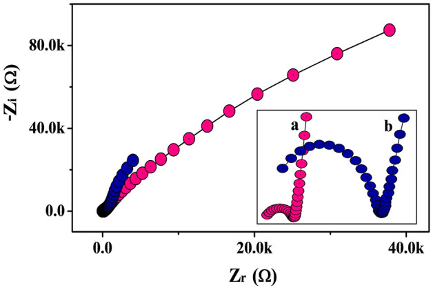
The Nyquist plots for MWCNTPE (Line ‘b’) and Poly(TY-G)LMWCNTPE (Line ‘a’).
Electro-active surface area of MWCNTPE and Poly(TY-G)LMWCNTPE
Firstly, the investigative K4[Fe(CN)6]·3H2O solution (1.0 mM) in supporting electrolyte KCl (0.1 M) was employed with the CV method at both modified and unmodified electrodes separately. Figure 3 shows the cyclic voltammograms (CVs, at the potential scan rate of 0.1 V/s and potential width of − 0.2 to 0.6 V) for K4[Fe(CN)6]·3H2O at the surface of MWCNTPE (Line ‘a’) and Poly(TY-G)LMWCNTPE (Line ‘b’) in optimum conditions. It can be displayed that, the Poly(TY-G)LMWCNTPE reveals a greater redox peak current in association with unmodified MWCNTPE. The electro-active area of MWCNTPE and Poly(TY-G)LMWCNTPE surfaces was computed on the application of following Randles–Sevcik’s equation29,32,
| 1 |
where, ‘A’ is the electro-active area of the electrode surface (cm2), ‘Ip’ is the peak current (A), ‘n’ is the number of electrons involved in the redox reaction of K4[Fe(CN)6]·3H2O, ‘D’ is the diffusion coefficient (cm2/s) of K4[Fe(CN)6]·3H2O, ‘C0’ is the concentration (mol/cm3) of K4[Fe(CN)6]·3H2O and ‘ʋ’ is the fixed potential scan rate of CVs (V/s). The calculated electro-active surface areas of the MWCNTPE and Poly(TY-G)LMWCNTPE are obtained to be 0.0149 cm2 and 0.0389 cm2, respectively.
Figure 3.
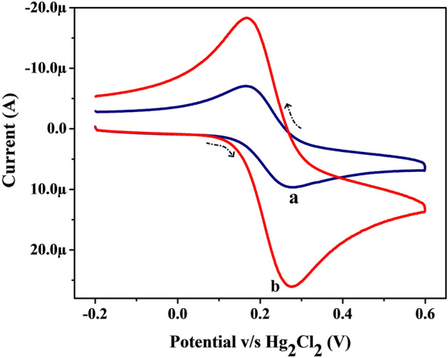
CVs for K4[Fe(CN)6]·3H2O (1.0 mM) in the supporting electrolyte KCl (0.1 M) on the surface of MWCNTPE (Line ‘a’) and Poly(TY-G)LMWCNTPE (Line ‘b’) at the potential scan rate of 0.1 V/s and the potential width of − 0.2 to 0.6 V versus Hg2Cl2.
Electro-polymerization of TY-G on MWCNTPE
The polymer film thickness has a significant impact on the electrochemical feature of the Poly(TY-G)LMWCNTPE. The poly(TY-G) film thickness can be inhibited efficiently through the variation of a number of electro-polymerization cycles. Hence, the optimization of number of polymerization cycles were premeditated on the electrochemical action of FLFT (0.01 mM) in PB (0.2 M and 7.0 pH). Figure 4a displays the plot of oxidation peak current versus the number of electro-polymerization cycles. Here we observed the amplified oxidation peak current of FLFT from 5 to 10 cycles, on the other hand from 10 to 25 cycles the FLFT oxidation peak current gradually decreased, which is most feasibly due to the sufficient coverage of poly(TY-G) film on the accessible surface area of the MWCNTPE. Here, ten polymerization cycles show sufficient coverage on the surface of MWCNTPE and provide a faster rate of electron transfer with optimum peak current and the reduction of background current. As a result, ten polymerization cycles were chosen as optimum cycles for this experimentation.
Figure 4.
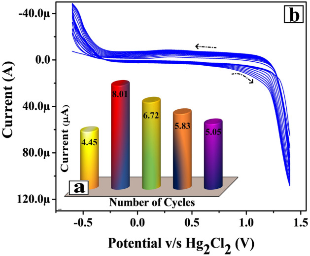
(a) Plot of the electro-oxidation peak current of FLFT versus the number of electro-polymerization cycles. (b) CVs for the electro-polymerization of TY-G (1.0 mM) in PB (0.2 M and 7.0 pH) on the surface of MWCNTPE at the potential scan rate of 0.1 V/s and the potential interface of − 0.60 to 1.40 V versus Hg2Cl2.
The unification of TY-G dye polymer film on the MWCNTPE surface was done by treating 1.0 mM monomer TY-G dye solution in 0.2 M PB (supportive electrolyte) of 7.0 pH in an electrochemical chamber through the CV approach. The conversion of a monomer TY-G into a polymer of TY-G was accomplished by the electro-polymerization process. The electro-polymerization of TY-G on the MWCNTPE surface was completed using optimized ten polymerization CV cycles (at the potential interface of − 0.60 to 1.40 V and 0.1 V/s of potential scan rate) shown in Fig. 4b. Here Fig. 4b exemplifies the progressively inclined CVs during the increased cyclic time, confirms the conversion of a monomer TY-G film into an electro-polymer TY-G film. The obtained poly(TY-G) may have more π–π covalent interactions with the aromatic rings in their polymeric form and provides strong incorporation on the surface of MWCNTPE through hydrophobic interactions33. The probable reaction mechanism of electro-polymerization of TY-G on the surface of MWCNTPE is shown in Scheme 1.
Scheme 1.

The probable reaction mechanism of electro-polymerization of TY-G on the surface of MWCNTPE.
Impact of electrolyte pH on FLFT peak potential and current
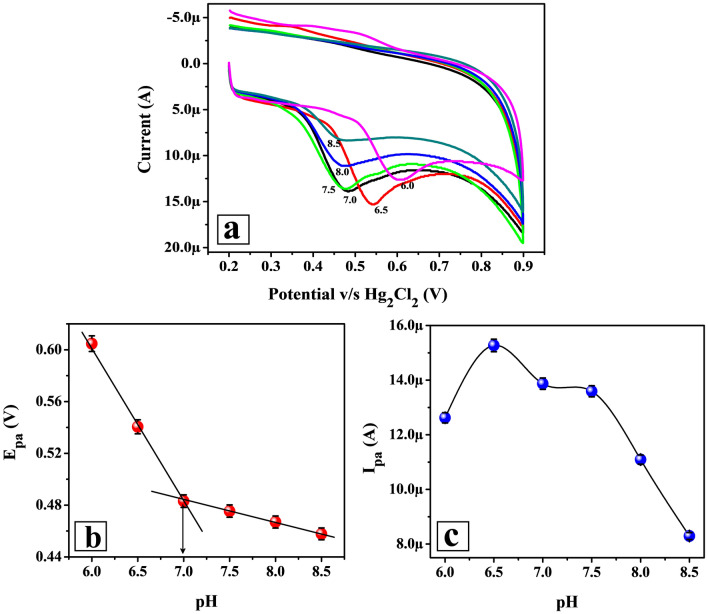
The impact of supporting electrolyte pH was analyzed using the CV method (at 0.1 V/s potential scan rate and 0.2 to 0.9 V potential gap) for 0.01 mM FLFT in different pHs of 0.2 M PB (6.0 to 8.5) on the surface of Poly(TY-G)LMWCNTPE (Fig. 5a). FLFT has both amino and phenolic groups in its chemical structure which delivers the pKa values of 9.2 and 7.9 at 25 ± 2 °C, respectively. Thus, the supporting electrolyte (0.2 M PB) pH modifies the state of FLFT protonation on the surface of Poly(TY-G)LMWCNTPE. Figure 5b espied that the electro-oxidation peak potential of FLFT was transferred towards a shorter potential zone (negative shift) as the intensification of PB pH from 6.0 to 8.5. This incident specified that on the surface of Poly(TY-G)LMWCNTPE the electro-oxidation process of FLFT was a protonated electron transfer. Hence, the smaller number of protons participation supports the process of electro-oxidation with less current sensitivity at elevated PB pH (6.5 to 8.5). Fine linearity is observed between peak potential and PB pH values (plot of Epa v/s pH) and the fitted linear regression equation is as follows,
| 2 |
where, ‘R2’ is the regression coefficient. Here, the slope value 0.055 V/pH is most nearer to the theoretic value (0.059 V/pH), signifying that the electro-oxidation of FLFT associates with an alike number of protons and electrons on the surface of Poly(TY-G)LMWCNTPE. Supporting this, the number of protons that participated in the electro-oxidation reaction of FLFT was determined using the following Nernst relation,
| 3 |
where, ‘B’ is the slope of Eq. (2), ‘m’ is the number of protons that participated in the FLFT oxidation reaction, ‘n’ is the number of electrons participating in the FLFT oxidation reaction and other terms (R, T and F) represents their standard physical values. The calculated value of the number of protons was found to be 1.86 ≈ 2.
Figure 5.
(a) CVs for 0.01 mM FLFT in different pHs of 0.2 M PB (6.0 to 8.5) on the surface of Poly(TY-G)LMWCNTPE at the potential scan rate of 0.1 V/s and the potential interface of − 0.60 to 1.40 V versus Hg2Cl2. (b) The plot of the pH of 0.2 M PB versus the electro-oxidation peak potential of FLFT (n = 6). (c) The plot of the pH of 0.2 M PB versus the electro-oxidation peak current of FLFT (n = 6).
Furthermore, the pKa value of FLFT after the electro-oxidation was detected from the intersection point displayed in the plot of Epa v/s pH (Fig. 5b). FLFT displays the pKa value of 7.0, indicating that the oxidation process most probably has taken place at the phenolic group of FLFT. From Fig. 5c, the electro-oxidation peak current of FLFT was very high at acidic pH of 6.5. These data are resolute that acidic pH (6.5) is most appropriate for the highly sensitive sensing of FLFT due to the strong interaction between Poly(TY-G)LMWCNTPE surface and FLFT. Therefore, the pH value of 6.5 was chosen as the optimal pH for this investigation.
Scan rate impact on peak potential and current of FLFT at Poly(TY-G)LMWCNTPE
The potential scan rate impact on the peak potential and current of FLFT at Poly(TY-G)LMWCNTPE deliver a key evidence for the electro-oxidation mechanism and the kinetic behaviors of the equipped electrode. The CV executions were documented and shown in Fig. 6a for 0.005 mM FLFT in PB (0.2 M and 6.5 pH) on Poly(TY-G)LMWCNTPE at variable potential scan rate in the range between 0.05 and 0.25 V/s, which displays the increased electro-oxidation peak currents and potentials of FLFT. The kinetic nature and dependability of the modified electrode towards the oxidation reaction of FLFT were verified based on acceptable linear plots of the log value of the electro-oxidation peak current versus log value of the potential scan rate (Fig. 6b) and electro-oxidation peak current versus square root value of the potential scan rate (Fig. 6c). The obtained results are fitted in the following linear relations are as follows,
| 4 |
| 5 |
Figure 6.
(a) CVs for 0.005 mM FLFT in PB (0.2 M and 6.5 pH) on the surface of Poly(TY-G)LMWCNTPE at variable potential scan rate in the range between 0.05 to 0.25 V/s and the potential window of 0.2 to 0.9 V versus Hg2Cl2. (b) The plot of the log value of electro-oxidation peak current versus the log value of potential scan rate (n = 9). (c) The plot of the electro-oxidation peak current versus the square root value of potential scan rate (n = 9). (d) The plot of the electro-oxidation peak potential versus the log value of potential scan rate (n = 9).
The slope (0.412 ± 0.023) of Eq. (4) and the R2 value of Eq. (5) are very adjacent to the required theoretical values suggesting that the kinetic behavior of the electro-oxidation of FLFT on Poly(TY-G)LMWCNTPE has proceeded through a diffusion-controlled pathway26. The plot of electro-oxidation peak potential versus log value of the potential scan rate (Fig. 6d) provides fine linearity and the results are fitted in the following linear relation is as follows,
| 6 |
The number of electrons that participated in the electro-oxidation reaction of FLFT was confirmed using the slope value (0.045 ± 0.002) of Eq. (6) and the following Laviron’s and Bard-Faulkner’s relations34,35,
| 7 |
| 8 |
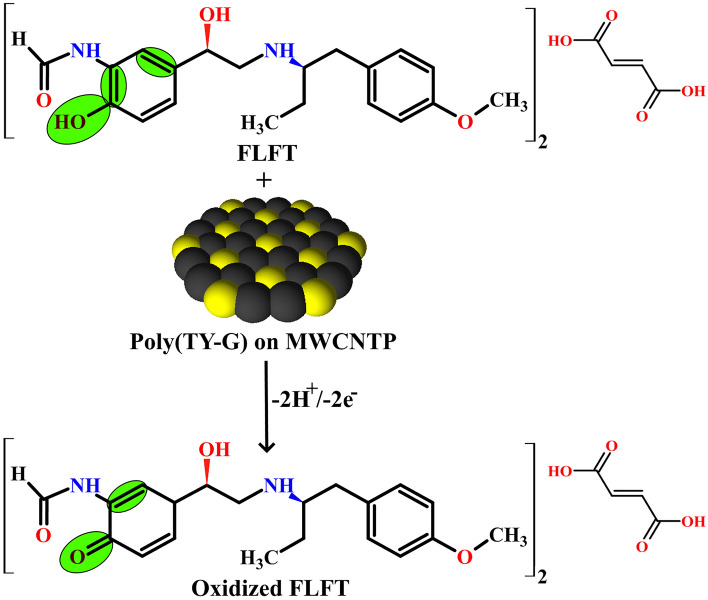
where, ‘Epa/2’ is the electro-oxidation peak potential at the half peak current of FLFT, ‘α’ is the electrochemical charge transfer coefficient, ‘n’ is the number of involved electrons, ‘υ’ is the applied potential scan rate, ‘k0’ is the electrochemical heterogeneous rate constant, and other terms (R, T, and F) represents their standard physical values. The premeditated value of a number of electrons was found to be 2.26 ≈ 2. The possible electro-oxidation reaction of FLFT is shown in Scheme 2. The electrochemical heterogeneous rate constant for the oxidation of FLFT was calculated by deducing Eq. (7) and the premeditated value of ‘k0’ was found to be 1.818 s−1.
Scheme 2.
The probable electro-oxidation reaction of FLFT on the surface of Poly(TY-G)LMWCNTPE.
The electrochemical surface coverage concentration (Г) of FLFT at the surface of MWCNTPE and Poly(TY-G)LMWCNTPE is calculated using the following relation36,
| 9 |
where, ‘Q’ is the integrated electrical charge of the oxidation peak. The calculated value of electrochemical surface coverage concentration of FLFT for the MWCNTPE was 1.286 ÅM/cm2 and for the Poly(TY-G)LMWCNTPE was 2.802 ÅM/cm2. This consequence is the other key factor for the high electro-oxidation peak current of FLFT at Poly(TY-G)LMWCNTPE.
Oxidation peak growth time
The influence of peak growth time is the prominent tool to disclose the maximum accumulation point (higher peak current) of FLFT on the surface of Poly(TY-G)LMWCNTPE with its kinetic behavior at the variable growth time. The peak growth time has been optimized using the DPV experimentation by altering the growth time within the range from 0 to 100 s for 0.005 mM FLFT in PB (0.2 M and 6.5 pH) and the outcomes are presented in Fig. 7. Here the observation suggests that the growth time of 20 s (exists at the second position) provides the maximum peak current than other growth times (0 s, 40 s, 60 s, 80 s, and 100 s). This consequence is most probably due to the effect of saturation followed by diffusion kinetic behavior of the equipped Poly(TY-G)LMWCNTPE rather than adsorption kinetics. Hence, twenty seconds were chosen as an optimum growth time for the FLFT analysis throughout the experiment.
Figure 7.

DPVs of the altered growth time (0 to 100 s) for 0.005 M FLFT in PB (0.2 M and 7.0 pH) on the surface of Poly(TY-G)LMWCNTPE and the plot of growth time versus electro-oxidation peak current of FLFT.
Electro-oxidation of FLFT at Poly(TY-G)LMWCNTPE and MWCNTPE
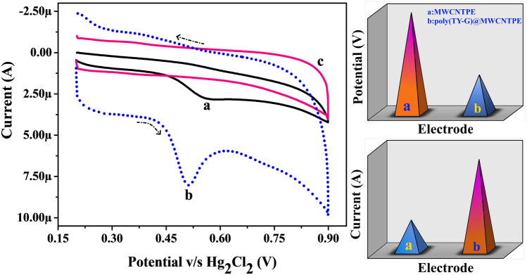
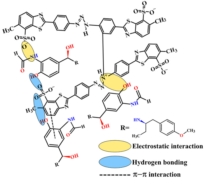
The electro-oxidation nature of FLFT on the surface of bare MWCNTPE and Poly(TY-G)LMWCNTPE has been discussed by documenting the CVs at the optimum experimental incidents. Figure 8 parades the CVs at the potential scan rate of 0.1 V/s and the potential width of 0.2 to 0.9 V during the presence and absence (Line ‘c’) of 0.005 mM FLFT in PB (0.2 M and 6.5 pH) on the surface of Poly(TY-G)LMWCNTPE (Line ‘b’) and MWCNTPE (Line ‘a’). In the presence of FLFT, a fine electro-oxidation peak is viewed at the potential of 0.514 V as compared to bare MWCNTPE, which shows a less enhanced electro-oxidation peak at the potential of 0.569 V. Furthermore, modified electrode provides elevated electro-oxidation peak current and lesser electro-oxidation peak potential for FLFT than the bare MWCNTPE delivers an exceptional electro-catalytic potential. This shift in both the current and potential at the modified electrode is most conceivably due to the various interactions between FLFT molecules and poly(TY-G), such as π–π covalent, hydrogen bonding, electrostatic, and dipole–dipole interactions, shown in Scheme 337. Furthermore, in the absence of FLFT in PB (0.2 M and 6.5 pH), the surface of Poly(TY-G)LMWCNTPE didn’t show any electro-catalytic oxidation response.
Figure 8.
CVs for the presence and absence (Line ‘c’) of 0.005 mM FLFT in PB (0.2 M and 6.0 pH) on the surface of Poly(TY-G)LMWCNTPE (Line ‘b’) and MWCNTPE (Line ‘a’) at the potential scan rate of 0.1 V/s and the potential width of 0.2 to 0.9 V versus Hg2Cl2.
Scheme 3.
The probable scheme of π–π, hydrogen bonding, electrostatic, and dipole–dipole interactions between FLFT molecules and poly(TY-G).
Calibration plot for FLFT with and without UA
The detection capability of the prepared Poly(TY-G)LMWCNTPE towards FLFT was verified based on the concentration variation method in the presence and absence of UA using the DPV technique (Inset Fig. 9). Figure 9a shows the documented differential pulse voltammograms (DPVs) of different concentrations of FLFT in the range from 0.2 to 3.0 μM in PB (0.2 M and pH 6.5) at the surface of Poly(TY-G)LMWCNTPE. Here, the electro-oxidation peak current of FLFT enhanced as the concentration of FLFT increased (Fig. 9b); also, the preliminary concentration range 0.2 to 1.5 μM gives a finer linear correlation and the achieved results are fitted in the following linear relation is as follows,
| 10 |
Figure 9.
(a) DPVs for the different concentrations of FLFT in the range from 0.2 to 3.0 μM in PB (0.2 M and 6.5 pH) on the surface of Poly(TY-G)LMWCNTPE at the potential gap of 0.3 to 0.6 V versus Hg2Cl2. (b) The plot of the concentration of FLFT versus the electro-oxidation peak current of FLFT (n = 6). (c) DPVs for FLFT and UA in PB (0.2 M and pH 6.5) on the surface of Poly(TY-G)LMWCNTPE (Line ‘b’) and MWCNTPE (Line ‘a’) at the potential gap of 0.25 to 0.7 V versus Hg2Cl2. (d) DPVs for the different concentrations of FLFT and UA in the range from 0.3 to 0.8 μM in PB (0.2 M and pH 6.5) on the surface of Poly(TY-G)LMWCNTPE at the potential gap of 0.25 to 0.7 V versus Hg2Cl2. (e) The plot of the concentration of FLFT and UA versus the electro-oxidation peak current of FLFT and UA (n = 6).
The LOD and limit of quantification (LOQ) values are determined based on the slope of Eq. (10) and the standard deviation of the five consecutive blank cycles. The deliberated LOD and LOQ values were found to be 0.0128 µM and 0.0427 µM, respectively. The high sensing proficiency of the presented electrode associate with previous FLFT sensors is deliberated in Table 111,12,14,26,27, proposing that the Poly(TY-G)LMWCNTPE provides the lowest/very nearer LOD.
Table 1.
Contrast of earlier reported techniques, electrodes, and LODs of FLFT with the current work.
| Method | Electrode | Buffer solution | Linear range (µM) | LOD (µM) | References |
|---|---|---|---|---|---|
| HPLC | – | Ammonium acetate with Acetic acid | 1.0–50.0 | 0.071 | 11 |
| IPC | – | Acetate | 0.05–6.0 | 0.021 | 12 |
| RP-HPLC | – | Acetonitrile | 0.03–3.1 | 0.037 | 14 |
| DPV | Suberic acid functionalized CuO NFs@glassy carbon electrode | Britton-Robinson | 0.1–5.0 | 0.010 | 26 |
| SWVa | Glassy carbon electrode | H2SO4 | 8.0–60.0 | 0.404 | 27 |
| DPV | 0.354 | ||||
| DPV | Poly(TY-G)MMWCNTPE | PB | 0.2–1.5 | 0.0128 | Current effort |
aSquare wave voltammetry.
The simultaneous examination of FLFT and UA in PB (0.2 M and pH 6.5) was performed using the DPV technique on the surface of Poly(TY-G)LMWCNTPE (Line ‘b’) and MWCNTPE (Line ‘a’) (Fig. 9c). The line ‘b’ discloses well and distinctive electro-oxidation peaks resultant to UA and FLFT at the electro-oxidation peak potentials of 0.321 V and 0.409 V, individually with the lack of a background current. Nevertheless, at MWCNTPE the individual peak split-up is not definite for FLFT and UA. This consequence states that Poly(TY-G)LMWCNTPE is a sensitive tool for the selective and innovative assessment of FLFT in the occurrence of UA. Figure 9d displays the recorded DPVs of different concentration of FLFT and UA in the range from 3.0 to 8.0 μM in PB (0.2 M and pH 6.5) at Poly(TY-G)LMWCNTPE. The electro-oxidation peak current of FLFT and UA get promoted as the concentration of FLFT and UA increased (Fig. 9e) and FLFT offers a better linear association in the presence of UA and the results are fitted in the following relation is as follows,
| 11 |
The determined LOD value was found to be 0.0129 µM, suggesting that the Poly(TY-G)LMWCNTPE delivers almost nearer LOD value even in the presence of interfering UA molecule. Hence, the prepared electrode is almost free from interference.
Compatibility of the Poly(TY-G)LMWCNTPE
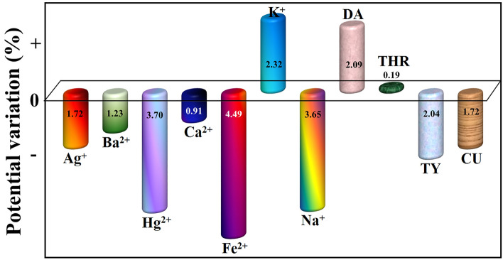
The compatibility of the Poly(TY-G)LMWCNTPE towards the electro-oxidation of FLFT was examined via the DPV method in the presence of some biologically available species (metal ions and organic molecules, each having a concentration of 1.0 mM). Figure 10 shows the graph of different chemical species (such as Ag+, Ba2+, Hg2+, Ca2+, Fe2+, K+, Na+, dopamine (DA), tryptophan (THR), tyrosine (TY), and curcumin (CU)) versus the % of electro-oxidation potential variation of FLFT. Here we observe only ± 5.0% of potential variation at the oxidation of FLFT, suggesting that Poly(TY-G)LMWCNTPE shows acceptable compatibility in presence of the above-mentioned chemical species. But in the case of electro-oxidation peak current, the compatibility was little vary compared to the base peak current.
Figure 10.
The plot of the different chemical species (Ag+, Ba2+, Hg2+, Ca2+, Fe2+, K+, Na+, DA, THR, TY, and CU) versus the electro-oxidation potential variation of FLFT in PB (0.2 M and 6.5 pH).
Analysis of FLFT in medicinal sample
In supplement to the aforesaid studies, the Poly(TY-G)LMWCNTPE sensing capability towards FLFT was determined in a medicinal sample based on the standard addition approach. As from Table 2, the five consecutive FLFT concentrations in the range from 0.6 to 2.0 µM give a fine recovery in the range from 90.64 to 96.70% with a good LOD (0.150 µM) and relative standard deviation (RSD) (1.87%). These obtained data show the good sensing ability of Poly(TY-G)LMWCNTPE for FLFT analysis in a medicinal sample.
Table 2.
Result of percentage recovery, LOD, and RSD of FLFT at Poly(TY-G)LMWCNTPE in a medicinal sample.
| Sample | Added (µM) | Found (µM) | Recovery (%) | LOD (µM) | RSD (%) |
|---|---|---|---|---|---|
| FLFT capsule (n = 5) | 0.60 | 0.58 | 96.37 | 0.150 | 1.876 |
| 0.80 | 0.77 | 96.70 | |||
| 1.00 | 0.91 | 91.22 | |||
| 1.50 | 1.35 | 90.64 | |||
| 2.00 | 1.87 | 93.85 |
Repeatability, reproducibility, and stability of Poly(TY-G)LMWCNTPE
Repeatability, reproducibility, and stability are the supplemental factors to reveal the consistency and practicability of a used method and developed electrode. The repeatability of Poly(TY-G)LMWCNTPE was analyzed by cycling five sequential CV cycles for 0.005 mM FLFT in 0.2 M PB of pH 6.5 (renewed at the end of each cycle) on the surface of constantly fixed Poly(TY-G)LMWCNTPE. The found RSD value of 1.36% delivers a fine repeatability of the used method and the developed electrode towards the FLFT oxidation. The reproducibility of Poly(TY-G)LMWCNTPE was studied by cycling continual five CV cycles for constantly fixed 0.005 mM FLFT in PB (0.2 M and pH 6.5) on the surface of Poly(TY-G)LMWCNTPE (renewed at the end of each CV cycle). The found RSD value of 2.16% offers a good reproducibility for the operated method and developed electrode towards the oxidation of FLFT. Likewise, the storage stability of the developed electrode was tested towards 0.005 mM FLFT in PB (0.2 M and pH 6.5) via the DPV method by quantifying the current response at the Poly(TY-G)LMWCNTPE (initial current and current after one day). The calculated value of the percentage of degradation gives 90.72% of retained peak current affords a first-class electrode storage stability.
Conclusions
In this effort, the Poly(TY-G)LMWCNTPE and MWCNTPE were prepared simplistically and economically for the detection of FLFT in PB using the CV and DPV methodologies. The modification of poly(TY-G) on MWCNTPE was confirmed by FE-SEM, EIS, CV, electro-active surface area, and surface concentration measurements. The enhanced active surface area of the Poly(TY-G)LMWCNTPE improves the rate of electron and proton transfer during the electro-oxidation of FLFT. The CV outcomes validate different interactions between FLFT molecules and Poly(TY-G)LMWCNTPE, which significantly shifts the peak current to a higher level and peak potential to a lower level in the oxidation of FLFT. The impact of the potential scan rate study reveals the heterogeneous rate constant and diffusion kinetics (also supported by the effect of accumulation) with the transfer of 2 e− and 2 H+ in the electro-oxidation of FLFT. The supporting electrolyte pH study shows that the proportion of electron and proton transfer in the electro-oxidation of FLFT is equivalent (1:1). The Poly(TY-G)LMWCNTPE implicates better electrochemical behavior (in presence and absence of UA) with fine linear response, superior sensitivity with lower LOD, first-class selectivity (in the presence of different chemical species), reproducibility, repeatability, and good storage stability. Additionally, the modified Poly(TY-G)LMWCNTPE provides excellent recovery (90.64 to 96.70%) for FLFT in a medicinal sample. All these results concluded that the Poly(TY-G)LMWCNTPE is a more optimistic and potent sensing tool in the analysis of many other electro-active molecules and medicinal samples in vision of its superior active surface area and electrocatalytic activity.
Acknowledgements
We thankfully acknowledge the financial support from the Department of Science and Technology (DST), India for the INSPIRE Fellowship (Registration Number: IF180479).
Author contributions
N.H.: Conceive and designed the work, contributed to the data collection and performed the data analysis, interpretation and graphical presentation, contributed to critically review the article, contributed to the literature survey, contributed to the drafting of the article and the final approval of the submitted version. J.G.M.: Conceive and designed the work, contributed to the data collection and performed the data analysis, and interpretation, contributed to critically review the article, contributed to the drafting of the article and the final approval of the submitted version.
Competing interests
The authors declare no competing interests.
Footnotes
Publisher's note
Springer Nature remains neutral with regard to jurisdictional claims in published maps and institutional affiliations.
References
- 1.Ronald GC. Airway basal cells. The “smoking gun” of chronic obstructive pulmonary disease. Am. J. Respir. Crit. Care Med. 2014;190:1355–1362. doi: 10.1164/rccm.201408-1492pp. [DOI] [PMC free article] [PubMed] [Google Scholar]
- 2.Chan KH, Poon LL, Cheng VC, Guan Y, Hung IFN, Kong J, Yam LYC, Seto WH, Yuen KY, Peiris JSM. Detection of SARS coronavirus in patients with suspected SARS. Emerg. Infect. Dis. 2004;10:294–299. doi: 10.3201/eid1002.030610. [DOI] [PMC free article] [PubMed] [Google Scholar]
- 3.Brazier, Y. M. Types, Causes, and Diagnosis of Asthma (Reviewed by M. Meth). Accessed 21 May 2020. https://www.medicalnewstoday.com/articles/323523.
- 4.Garg S, Kim L, Whitaker M, O’Halloran A, Cummings C, Holstein R, Prill M, et al. Hospitalization rates and characteristics of patients hospitalized with laboratory-confirmed coronavirus disease 2019-COVID-NET, 14 States, March 1–30, 2020. Morb. Mortal. Wkly. Rep. 2020;69:458–464. doi: 10.15585/mmwr.mm6915e3. [DOI] [PMC free article] [PubMed] [Google Scholar]
- 5.The New York Times. Asthma Is Absent Among Top Covid-19 Risk Factors, Early Data Shows. Section A. Accessed 21 May 2020. https://www.nytimes.com/2020/04/16/health/coronavirus-asthma-risk.html.
- 6.O'Neil MJ, Heckelman PE, Dobbelaar PH, Roman KJ, Kenney CM, Karaffa LS, editors. The Merck Index: An Encyclopedia of Chemicals, Drugs and Biological. 15. Cambridge Royal Society of Chemistry; 2013. [Google Scholar]
- 7.Vogelmeier CF, Criner GJ, Martinez FJ, Anzueto A, Barnes PJ, Bourbeau J, Celli BR, et al. Global strategy for the diagnosis, management, and prevention of chronic obstructive lung disease 2017 report. Respirology. 2017;22:575–601. doi: 10.1111/resp.13012. [DOI] [PubMed] [Google Scholar]
- 8.Hardman JG, Limbird LE. The Pharmacological Basis of Therapeutics. 9. The McGraw-Hill Companies; 1996. p. 1905. [Google Scholar]
- 9.Patil AT, Patil SD, Shaikh KA. Sensitive LC method for simultaneous determination of ciclesonide and formoterol fumarate in dry powder inhaler. J. Liq. Chrom. Relat. Tech. 2011;34:1568–1577. doi: 10.1080/10826076.2011.575980. [DOI] [Google Scholar]
- 10.Mazzarino M, de la Torre X, Fiacco I, Pompei C, Calabrese F, Botrè F. A simplified procedure for the analysis of formoterol in human urine by liquid chromatography-electrospray tandem mass spectrometry: Application to the characterization of the metabolic profile and stability of formoterol in urine. J. Chromatogr. B Analyt. Technol. Biomed. Life Sci. 2013;931:75–83. doi: 10.1016/j.jchromb.2013.05.021. [DOI] [PubMed] [Google Scholar]
- 11.Merey HA, El-Mosallamy SS, Hassan NY, El-Zeany BA. Validated chromatographic methods for the simultaneous determination of Mometasone furoate and Formoterol fumarate dihydrate in a combined dosage form. Bull. Fac. Pharm. Cairo Univ. 2016;54:99–106. doi: 10.1016/j.bfopcu.2016.02.001. [DOI] [Google Scholar]
- 12.Salem YA, Shaldam MA, El-Sherbiny DT, El-Wasseef DR, El-Ashry SM. Simultaneous determination of formoterol fumarate and budesonide epimers in metered dose inhaler using ion-pair chromatography. J. Chromatogr. Sci. 2017;55:1013–1020. doi: 10.1093/chromsci/bmx067. [DOI] [PubMed] [Google Scholar]
- 13.Gousuddin M, Raju SA, Sultanuddin MS. Development and validation of spectrophotometric methods for estimation of formoterol bulk drug and its pharmaceutical dosage forms. Int. J. Pharm. Pharm. Sci. 2011;3:306–309. [Google Scholar]
- 14.Akapo SO, Asif M. Validation of a RP-HPLC method for the assay of formoterol and its related substances in formoterol fumarate dihydrate drug substance. J. Pharm. Biomed. Anal. 2003;33:935–945. doi: 10.1016/S0731-7085(03)00425-4. [DOI] [PubMed] [Google Scholar]
- 15.Song JZ, Chen J, Tian SJ, Sun ZP. Assay for the determination of low dosage form of formoterol dry syrup by capillary electrophoresis with head-column field-amplified sample stacking. J. Pharm. Biomed. Anal. 1999;21:569–576. doi: 10.1016/S0731-7085(99)00158-2. [DOI] [PubMed] [Google Scholar]
- 16.Manjunatha JG, Deraman M. Graphene paste electrode modified with sodium dodecyl sulfate surfactant for the determination of dopamine, ascorbic acid and uric acid. Anal. Bioanal. Electrochem. 2017;9:198–213. [Google Scholar]
- 17.Karimi-Maleh H, Marzieh A, Yasin O, Fatemeh K, Mehdi B, Jalal R, Somayeh T, Beitollahi H, Shilpi A, Gupta VK, Saravanan R, Sadegh R, Li F, Saberi-Movahed F, Samira M. Guanine-based DNA biosensor amplified with Pt/SWCNTs nanocomposite as analytical tool for nanomolar determination of daunorubicin as an anticancer drug: A docking/experimental investigation. Ind. Eng. Chem. Res. 2021;60:816–823. doi: 10.1021/acs.iecr.0c04698. [DOI] [Google Scholar]
- 18.Beitollahi H, Mohammadi SZ, Safaei M, Tajik S. Applications of electrochemical sensors and biosensors based on modified screen-printed electrodes: A review. Anal. Methods. 2020;12:1547–1560. doi: 10.1039/C9AY02598G. [DOI] [Google Scholar]
- 19.Karimi-Maleh H, Fatemeh K, Yasin O, Ghobad M, Amir R, Aysenur A, Sen F. A new nickel-based co-crystal complex electrocatalyst amplified by NiO dope Pt nanostructure hybrid: A highly sensitive approach for determination of cysteamine in the presence of serotonin. Sci. Rep. 2020;10:11699. doi: 10.1038/s41598-020-68663-2. [DOI] [PMC free article] [PubMed] [Google Scholar]
- 20.Pushpanjali PA, Manjunatha JG, Amrutha BM, Hareesha N. Development of carbon nanotube-based polymer-modified electrochemical sensor for the voltammetric study of Curcumin. Mater. Res. Innov. 2020 doi: 10.1080/14328917.2020.1842589. [DOI] [Google Scholar]
- 21.Karimi-Maleh H, Kemal C, Kubilay A, Aysun S, Fatemeh K, Sen F. Palladium-Nickel nanoparticles decorated on Functionalized-MWCNT for high precision non-enzymatic glucose sensing. Mater. Chem. Phys. 2020;250:123042. doi: 10.1016/j.matchemphys.2020.123042. [DOI] [Google Scholar]
- 22.Karimi-Maleh H, Fatemeh K, Samira M, Nilofar Z, Roghayeh E, Sadegh R, Mehmet LY, Necip A, Shirin M, Saravanan R, Amir R, Yasin O, Shilpi A, Gupta VK. An amplified voltammetric sensor based on platinum nanoparticle/polyoxometalate/two-dimensional hexagonal boron nitride nanosheets composite and ionic liquid for determination of N-hydroxysuccinimide in water samples. J. Mol. Liq. 2020;310:113185. doi: 10.1016/j.molliq.2020.113185. [DOI] [Google Scholar]
- 23.Tahernejad-Javazmi F, Shabani-Nooshabadi M, Karimi-Maleh H. Analysis of glutathione in the presence of acetaminophen and tyrosine via an amplified electrode with MgO/SWCNTs as a sensor in the hemolyzed erythrocyte. Talanta. 2018;176:208–213. doi: 10.1016/j.talanta.2017.08.027. [DOI] [PubMed] [Google Scholar]
- 24.Alavi-Tabari SAR, Khalilzadeh MA, Karimi-Maleh H. Simultaneous determination of doxorubicin and dasatinib as two breast anticancer drugs uses an amplified sensor with ionic liquid and ZnO nanoparticle. J. Electroanal. Chem. 2018;811:84–88. doi: 10.1016/j.jelechem.2018.01.034. [DOI] [Google Scholar]
- 25.Gan T, Zhaoxia S, Danyang H, Zhen L, Junyong S, Yanming L. Preparation of yolk–shell structured copper oxide@silica oxide spheres and their application in high performance electrochemical sensing of Formoterol fumarate residues in swine feed and tissues. Food Chem. 2016;190:544–551. doi: 10.1016/j.foodchem.2015.05.132. [DOI] [PubMed] [Google Scholar]
- 26.Rajar K, Sirajuddin BA, Bhanger MI, Shaikh T. Suberic acid functionalized CuO NFs for enhanced electrochemical oxidation of formoterol fumarate. Sens. Actuators B Chem. 2017;246:1030–1038. doi: 10.1016/j.snb.2017.02.111. [DOI] [Google Scholar]
- 27.Demircigil BT, Özkan SA, Coruh Ö, Yılmaz S. Electrochemical behavior of formoterol fumarate and its determination in capsules for inhalation and human serum using differential pulse and square-wave voltammetry. Electroanalysis. 2002;14:122–127. doi: 10.1002/1521-4109(200201)14:2<122::aid-elan122>3.0.co;2-1. [DOI] [Google Scholar]
- 28.Yi N, Abidian MR. Conducting polymers and their biomedical applications. In: Poole-Warren L, Martens P, Green R, editors. Biomaterials, Biosynthetic Polymers for Medical Applications. Woodhead Publishing; 2016. pp. 243–276. [Google Scholar]
- 29.Hareesha N, Manjunatha JG. Surfactant and polymer layered carbon composite electrochemical sensor for the analysis of estriol with ciprofloxacin. Mater. Res. Innov. 2019;24:349–362. doi: 10.1080/14328917.2019.1684657. [DOI] [Google Scholar]
- 30.Li D, Wen Y, He H, Xu J, Liu M, Yue R. Poly pyrrole-multiwalled carbon nanotubes composites as immobilizing matrices of ascorbate oxidase for the facile fabrication of an amperometric vitamin C biosensor. J. Appl. Polym. Sci. 2012;126:882–893. doi: 10.1002/app.36526. [DOI] [Google Scholar]
- 31.Peng C, Zhang S, Jewell D, Chen GZ. Carbon nanotube and conducting polymer composites for super capacitors. Prog. Nat. Sci. 2008;18:777–788. doi: 10.1016/j.pnsc.2008.03.002. [DOI] [Google Scholar]
- 32.Hareesha N, Manjunatha JG. A simple and low-cost poly (dl-phenylalanine) modified carbon sensor for the improved electrochemical analysis of Riboflavin. J. Sci. Adv. Mater. Devices. 2020;5:502–511. doi: 10.1016/j.jsamd.2020.08.005. [DOI] [Google Scholar]
- 33.Shahrokhian S, Shamloofard M, Salimian R. Investigation of the electrochemical behavior of tizanidine on the surface of glassy carbon electrode modified with multi-walled carbon nanotube/titan yellow-doped polypyrrole. J. Electroanal. Chem. 2018;823:146–154. doi: 10.1016/j.jelechem.2018.06.005. [DOI] [Google Scholar]
- 34.Laviron E. Theoretical study of a reversible reaction followed by a chemical reaction in thin layer linear potential sweep voltammetry. J. Electroanal. Chem. 1972;39:1–23. doi: 10.1016/S0022-0728(72)80472-8. [DOI] [Google Scholar]
- 35.Bard AJ, Faulkner LR. Electrochemical Methods: Fundamentals and Applications. 2. Wiley; 2004. p. 864. [Google Scholar]
- 36.Amrutha BM, Manjunatha JG, Bhatt AS. Design of a sensitive and selective voltammetric sensor based on a cationic surfactant-modified carbon paste electrode for the determination of alloxan. ACS Omega. 2020;5:23481–23490. doi: 10.1021/acsomega.0c03517. [DOI] [PMC free article] [PubMed] [Google Scholar]
- 37.Giribabu K, Suresh R, Manigandan R, Munusamy S, Kumar SP, Muthamizh S, Narayanan V. Nanomolar determination of 4-nitrophenol based on a poly(methylene blue)-modified glassy carbon electrode. Analyst. 2013;138:5811–5818. doi: 10.1039/c3an00941f. [DOI] [PubMed] [Google Scholar]


