

Abstract
Study Design:
This study was a radiographic observational study for C1–C2 anthropometry.
Purpose:
The purpose of the study was to understand the anatomic relationship of C1–C2 in view of transarticular screw (TAS) fixation, to overcome the difficulties related with TAS placement, and to minimize the technique-related complications.
Materials and Methods:
It was an anthropometric observational study with retrospectively obtained anatomical data of randomly selected 116 patients from a single center. The anatomical measurements such as pars width, pars height, screw trajectory, and length were evaluated on the axial, sagittal, and three-dimensional reconstructed cervical CT scan using the radiant DICOM viewer software by the two fellowship trained spine surgeons which were blind to the study group details. The intra- and interobserver reliability with regard to the measured parameters was statistically analyzed.
Results:
The mean age of male and female was 28 and 29 years. The average BMI was calculated to be 23.5 and 25 for males and females, respectively. The mean right pars width in males was 5.78 ± 0.93 (range: 3.1–6.5 mm), while in female, it was 5.84 ± 0.95 (range: 3.1–6.5). The mean left pars width in males was 5.95 ± 1.13 (range: 3.8–8.1 mm), while in females, it was 5.70 ± 1.18 (range: 3.7–8.1 mm). Right side mean pars height in males was 5.90 ± 1.2 (range: 3.7–9.4 mm), and in females, it was 6.11 ± 1.04 (range: 3.8–9.3 mm). Left-sided mean pars height in males was 6.0 ± 1.1 (range: 3.2–9.4 mm) as compared to females, in which it was 5.77 ± 1.23 (range: 4.1–9.3 mm). The mean lateral angulation angle in males was 9.99° ± 1.70° (8.1°–15°), while in females, it was 10.15° ± 1.73° (8.1°–15°). The mean sagittal angulation in males was 26.33° ± 3.32° (21.0°–32.80°), while in females, it was 27.18 ± 3.05 (21.0°–32.10°). The average screw length in males was 41.74 ± 5.63 (34–54.8 mm), whereas in females, it was 41.35 ± 4.77 (34–54.8 mm).
Conclusion:
This study provides a morphometric database which is characteristic of the C1–C2 vertebrae in the normal Indian population with regard to the anatomic feasibility of the TAS fixation for various C1–C2 pathologies. The C2 pars width and height measured in the current study can guide the selection of TAS screws in the Indian population. This study could serve in providing the baseline anatomic parameters assessed in the healthy individuals to design and develop customized screws and related implant assembly which might provide wider clinical applicability.
Keywords: Anthropometry, atlantoaxial instability, C1–C2 joint, cervical spine, Indian population, trans-articular screw
INTRODUCTION
Anatomically, atlantoaxial joint is one of the most complex joints in the whole spine. Various pathological conditions compromise the stability of this joint including trauma, rheumatoid arthritis, malignancies, spinal deformities, and congenital malformations. The excessive mobility at the C1–C2 junction allying the axis and atlas is referred to as the “atlantoaxial instability (AAI).” Previously, semi-rigid implants such as sublaminar wiring were used they had their drawbacks such as the risk of damage to the dura during insertion of the wires and late compression of the cord by wire breakage or loosening. The posterior wiring construct has been used along with the bone graft in the traditional technique and is a significant modification, thereby avoiding the complications of sublaminar wire passage.[1] A practicing surgeon should be aware of the local anatomical measurements to avoid screw misplacement, leading to injuries to the surrounding anatomical structures such as a dural sac, hypoglossal nerve, and vertebral artery. Two transarticular screws with autogenous bone graft provide strong arthrodesis, as mentioned in various studies.[2,3,4,5,6] The robust and strong fixation is of utmost importance to prevent delayed neurological deficit and deformity. The “Posterior transarticular” screw (transarticular screw [TAS]) fixation with wiring techniques or laminar clamps is extensively approved measure adopted by the surgeons for C1/2 fusion. It was found that risk was particularly high for operating on atlantoaxial region due to its complex structure. Posterior TAS fixation[7,8] provides rigid fixation with a higher fusion rate and avoids the need for postoperative halo immobilization. Anatomically, this screw trajectory places the implant away from the spinal canal. Howbeit, it also allows decompression of dural sac if necessary.[9,10,11,12,13,14] It can be performed in fracture, destruction, or absence of the posterior arch of the atlas and anomalies of the odontoid process. It is found that approximately 10%–23% of sufferers who need “atlantoaxial arthrodesis” have anatomic abnormalities of the vertebral artery on any one side; thus posterior TAS fixation is difficult to perform with respect to these cases. TAS should be placed with precise knowledge and orientation of the anatomy of the respective joint with an accurate angle so as to prevent disastrous complications [Figure 1]. This technique displays a steep learning curve. The proper understanding of the anthropometry of the atlantoaxial joint reduces the learning curve associated with the precise placement of the TAS. Anthropometric evaluation is the estimation of the human quantitative measurements that primarily comprehend the physical abnormalities or in context to various physiological traits. This radiographic study was based on the assessment of the anthropometric parameters of C1 and C2 vertebrae in the Indian population for safe posterior TAS fixation. The anatomic landmarks and the positions must be decided preoperatively for successful AAI fixation. A CT scan-based study to evaluate the C1–C2 vertebrae's anatomic screw entry point, trajectory, length, and safety of the method in cervical spines of the Indian population. This study was conducted to aid in the safe and accurate TAS fixation for AAI.
Figure 1.

The direction of guidewire placed in transarticular screw
MATERIALS AND METHODS
It is an anthropometric observational study with retrospectively obtained anatomical data of randomly selected 116 patients from a single center. After taking ethical committee approval, the computed tomography (CT) scans of randomly selected 116 patients from a single center were isolated and studied to measure the anatomical parameters such as pars width, pars height, screw trajectory, and length of the screw. All the patients (age range: 18–45 years) with previously done cervical spine or brain CT scan with cervical spine screening done for various reasons were included and evaluated with the three-dimensional (3D) reconstruction of the first and the second cervical vertebrae. Patients who were skeletally immature, traumatic, with metastatic or inflammatory disease, infected, deformed, congenitally malformed, previous surgery, or showing signs of degeneration were excluded from the study. The anatomical measurements were performed on the axial, sagittal, and 3D-reconstructed CT scan using the radiant RadiAnt DICOM Viewer 2020.2.2 by Medixant, Poznan, Poland on each side of the vertebrae: C2 pars height, pars width, optimal surgical screw length, and optimal screw trajectory in sagittal and axial angles were measured by two senior spine fellows at different time intervals but with the same software after dividing the patients into an equal number of groups. The anatomical parameters were predefined before measurements as below.
The pars interarticularis
It is the narrowest portion between the superior and inferior facets [Figure 2]. It also introduces to a short part of the bone, connects or joins the facet joints in the back of the spine. A deficiency in this part is referred to as “spondylolysis.”
Figure 2.

Anatomical area showing the pars of C2 vertebrae
Height – It is measured on the first cut of vertebral artery foramen notch on sagittal cut of CT scan at different levels bilaterally, and the shortest value was considered as pars height [Figure 3]
Width – It is the area between the most medial point of the transverse foramen to most lateral point of the vertebral foramen [Figure 4]. It is measured on the axial cut of CT scan at different levels bilaterally, and the shortest value was considered as pars width [Figure 5].
Figure 3.

Height of C2 pars measured on the sagittal cut of CT scan
Figure 4.

Anatomical area showing the width of the C2 pars
Figure 5.
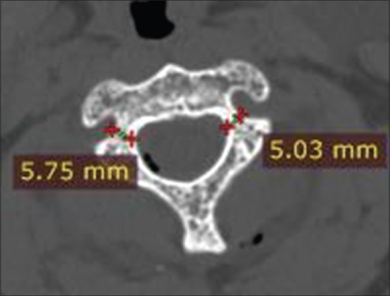
Measured C2 pars width on an axial CT cut
Coronal trajectory (angle) of the screw
It is the lateral trajectory of the screw in coronal plane [Figure 6]. The marker for transarticular screw entry point on the 3D-reconstructed coronal view is made as 2–3 mm medial from line drawn from the medial border of pars, just lateral to the spinous process of C2. The trajectory was determined on the basis of a retrograde projection. The angle made was the line drawn from this point toward the lamina, in the pars interarticularis through the facet joint of C1–C2 to the lateral mass of C1 till the anterior arch of the C1 (in sagittal view) with the perpendicular line drawn through the odontoid process [Figure 7]. The trajectory is medial to lateral, and care is taken keep it medial to the vertebral foramen to avoid vertebral artery injury. The same is repeated on the contralateral side.
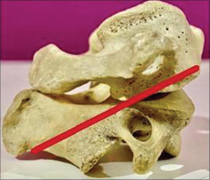
Figure 6.

Red line showing the lateral trajectory of the transarticular screw
Figure 7.

Lateral tracjectory of transarticular screw measured on the three-dimensional computed tomography
Sagittal angle of the screw
It is the superior trajectory of the screw in sagittal plane [Figure 8]. The angle made by the line drawn on the sagittal cut of CT scan along the direction of TAS which is from the anterior arch of C1 to the most dorsal part of the pedicle till the entry point of the C2 and another line just touching the inferior end plate of C2 vertebrae to this is made, and sagittal angle is measured [Figure 9].
Figure 8.
Red line showing the sagittal trajectory of the transarticular screw
Figure 9.

Measurement of the angle made by sagittal trajectory done on a CT scan
Length of the screw
Length of the screw [Figure 10] is measured on a parasagittal cut of a CT scan, a line is drawn from the tip of the arch of C1 to the entry point of the screw [Figure 11].
Figure 10.
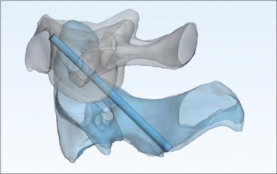
Model showing anatomical position of the transarticular screw
Figure 11.

Length of the transarticular screw measured on a CT scan
RESULTS
CT scan of 116 patients was selected, of which 76 were males and 40 were females. The mean age of male and female was 28 and 29 years. The average BMI was calculated to be 23.5 and 25 for males and females, respectively [Table 1]. The mean right pars width in males was 5.78 ± 0.93 (range: 3.1–6.5 mm), while in females, it was 5.84 ± 0.95 (range: 3.1–6.5). The mean left pars width in males was 5.95 ± 1.13 (range: 3.8–8.1 mm), while in females, it was 5.70 ± 1.18 (range: 3.7–8.1 mm). Right side mean pars height in males was 5.90 ± 1.2 (range: 3.7–9.4 mm), and in females, it was 6.11 ± 1.04 (range: 3.8–9.3 mm). Left side mean pars height in males was 6.0 ± 1.1 (range: 3.2–9.4 mm) compared to females, in which it was 5.77 ± 1.23 (range 4.1–9.3 mm). The mean lateral angulation angle in males was 9.99° ± 1.70° (8.1°–15°), while in females, it was 10.15° ± 1.73° (8.1°–15°). The mean sagittal angulation in males was 26.33° ± 3.32° (21.0°–32.80°), while in females, it was 27.18 ± 3.05 (21.0°–32.10°). The average screw length in males was 41.74 ± 5.63 (34–54.8 mm), whereas in females, it was 41.35 ± 4.77 (34–54.8 mm) [Table 2].
Table 1.
Patient demographic data
| Variable | Value (n=116) |
|---|---|
| Sex | |
| Male | 76 |
| Female | 40 |
| Average age (years) | |
| Male | 28.92 |
| Female | 29.50 |
| Average BMI | |
| Male | 23.53 |
| Female | 25.02 |
BMI-Body mass index
Table 2.
Mean and standard deviation specimen width and height
| Sex |
||||||
|---|---|---|---|---|---|---|
| Female |
Male |
|||||
| Mean±SD | Minimum | Maximum | Mean±SD | Minimum | Maximum | |
| Right pars width | 5.84±0.95 | 3.10 | 6.50 | 5.78±0.93 | 3.10 | 6.50 |
| Left pars width | 5.70±1.18 | 3.70 | 8.10 | 5.95±1.13 | 3.80 | 8.10 |
| Right pars height | 6.11±1.04 | 3.80 | 9.30 | 5.90±1.22 | 3.70 | 9.40 |
| Left pars height | 5.77±1.23 | 4.10 | 9.30 | 6.00±1.10 | 3.20 | 9.40 |
| Lateral angulation | 10.15±1.73 | 8.10 | 15.00 | 9.99±1.70 | 8.10 | 15.00 |
| Sagittal angulation | 27.18±3.05 | 21.00 | 32.10 | 26.33±3.32 | 21.00 | 32.80 |
| Screw length | 41.35±4.77 | 34.00 | 54.80 | 41.74±5.63 | 34.00 | 54.80 |
SD-Standard deviation
A paired t-test for measurement values taken by surgeon A and Surgeon B shows no statistical significance [Table 3].
Table 3.
T-test paired for Surgeon A and Surgeon B
| Surgeon A (mean) | Surgeon B (mean) | t-test (paired) | P | Result |
|---|---|---|---|---|
| 5.800862 | 5.782759 | 0.9781 | 0.4918 | Nonsignificant |
| 5.863793 | 5.75431 | 0.75748 | 0.4495 | Nonsignificant |
| 5.972155 | 5.868621 | 0.70044 | 0.4844 | Nonsignificant |
| 5.917414 | 5.845862 | 0.64254 | 0.48807 | Nonsignificant |
| 10.04569 | 10.33879 | −1.3988 | 0.1633 | Nonsignificant |
| 26.62069 | 26.61121 | 0.02227 | 0.9823 | Nonsignificant |
| 41.6069 | 41.84828 | −0.39192 | 0.6955 | Nonsignificant |
The statistical analysis was performed using the SPSS Inc. Released 2008. SPSS Statistics for Windows, Version 20.0, Chicago, IL. The mean values of the measured anatomical parameters were calculated among 116 selected patients.
DISCUSSION
The C1–C2 articulation contributes 45% of total rotational motion in the cervical spine.[8,15] “Posterior transarticular” screws are generally used for atlantoaxial instability fixation, to acquire the adequate results. Albeit, because of anatomical constraints and technical problems, an alternative technique including separate instrumentation in Atlas (C1) and Axis (C2) vertebra is frequently being used. This system was initially reported in 1994 and generalized by Jacobson and Khan.[16] It includes setting parallel lateral mass pins in C1 and pedicle/pars screws in C2 attached by a rod/plate. It is a very versatile and universal method, albeit accessing the C1 lateral mass can be challenging because of extreme bleeding from the venous plexus around the C1–C2 joint. There is also a chance of internal carotid artery and hypoglossal nerve damages due to bicortical screw placement. Because the C1 pedicle is merely under the vertebral artery groove on the C1 arch, measuring this area is the limiting factor in deciding the usefulness and screw size. Genetic and ethnic differences are representative of spinal structures, before mentioned as pedicles. These modifications may need effective adjustment for applicability of the techniques. “Atlas morphometry” is widely acknowledged form of research in the field; however, investigations regarding C1 pedicle morphometry are still scanty. The reports suggesting the application of “CT ‒ based” on Indian population is very limited. Numerous morphometric researches are being conducted to explore possible pathways for C1 pedicle screw placement and decide the usefulness of the system in an Indian population.[17]
The transarticular screw provides robust fixation and resists rotational instability after achieving successful bony fusion. The TAS technique illustrated by Magerl and Seemann was developed to provide immediate stabilization of the atlantoaxial joint. The need to measure various anatomical parameters surrounding the use of TAS is to understand the complex anatomic relationships of the C1–C2 joint and neurovascular structures. This knowledge of anthropometry is expected to overcome the difficulties related to TAS procedure, lessen the learning curve, and minimize the technique-related complications. CT scan with 3D reconstruction provided thorough anatomical aspects of the C1–C2 joint necessary for TAS, and it should be considered as an essential imaging tool to enhance this technique's effectiveness. Because of the complex and unique anatomy of C1–C2, transarticular screw fixation is technically challenging. The basic knowledge of anatomical parameters such as the mean value of the length of the total screw path, mean pars width, mean pars height, and screw trajectory angle provides a fair idea about the safe and effective screw placement. This information provides an impetus to avoid and minimize complications such as vertebral artery injury, spinal cord injury, and cranial nerve damage during a C1C2 stabilizing operation. Howbeit, limited studies are evaluating the C1–C2 anthropometry to the authors' knowledge. This study is most extensive to date in the Indian subcontinent that has considered 116 healthy Indian populations to assess the C1–C2 anatomical relationship in the view of the TAS technique.
To overcome the steep learning curve of the procedure, the authors believe that having an idea of length, width, and direction of the screw is of complete importance. Several previous types of research consider that 3D and multiplanar reconstructions have played a role in reducing the incidence of arterial injury through improved preoperative assessment of anatomic suitability.[18] Karaikovic et al. explore the measured isthmus height and width of C2 in their method in 53 human cadaveric cervical spines. They found that about 8.4% of their 53 specimens had widths <4 mm. They determined that the height of C2 was <5 mm in 11.9% of cases based on CT measurements, compared with 11.7% in the direct measurements.[19] Our study found that the height was <5 mm in 13.7%, which is 16 cases. In previous literature, 2.5 mm was taken to be equivalent to the safe limit, but Mandel et al. considered 5 mm of isthmus height and width as safe for TAS fixation.[20] The study establishes 5.5 mm to be a par height in the Indian population. C2 isthmus dimensions were measured previously for the placement of transarticular screws by Mandel et al.[20] The study also measured the isthmus height and width of different populations and methodology. The mean results were slightly different. Mandel et al. did not study the axis articular mass directly. In study, they found 11.7% of the narrowed isthmus and were found to be measuring <5 mm diameter.[20] In the present study, only 13.7% of C2 isthmus height was found to measure <5 mm. There are several studies in the literature which studied optimal screw length for transarticular arthrodesis, but they are limited by smaller sample size.[21,22] “Xu et al. allude to optimal screw length of TAS for C1–C2 fixation in the lateral radiograph.[23] The mean values of the present study, when compared to the previous studies, are almost comparable. The optimal screw length is an essential anatomical parameter as the area where the hypoglossal nerve lies are approximately 2–3 mm lateral to the middle of the anterior aspect of the C1 lateral mass.[21] Misdirected or long screws can cause hypoglossal nerve injury.”[22]
The limitations of this study are the small sample size, selection bias, and single-center study. The lack of similar comparative studies might be one of the limitations. Two trained spine fellows did the measurements at different times. Their anatomical and surgical knowledge can create variable results. The results, intra- and interobserver reliabilities of this study, should be verified with the extensive randomized or multicenter studies.
CONCLUSION
The feasibility of C1–C2 TAS stabilization is an excellent method for fusion of the atlantoaxial complex. Indian population comprises 17.71% of the total world population; therefore, acquired data concerning the specific demography account to one-sixth of the total data relating to spine researchers and Implant manufacturers. This study provides a database of morphometric characteristics on the C1–C2 vertebrae in the Indian population. The available database proves to be of great significance for future references. Further, it can detect pathological changes in the spine to enable operative interventions. Importantly, the C1–C2 pars width and height measured in the current study can guide the selection of TAS screws in the Indian population and stimulate further research. This study may be used to design and develop the applicability of screws and its implants in India. The validation of our study result can further evaluate the surgical feasibility of TAS through extensive multicenter randomized studies.
Financial support and sponsorship
Nil.
Conflicts of interest
There are no conflicts of interest.
REFERENCES
- 1.Carrier CS, Sama AA, Girardi FP, Lebl DR. Anterior transarticular screw fixation for atlantoaxial arthrodesis: A report of two cases. J Craniovertebr Junction Spine. 2013;4:85–9. doi: 10.4103/0974-8237.128540. [DOI] [PMC free article] [PubMed] [Google Scholar]
- 2.Smith MD, Phillips WA, Hensinger RN. Complications of fusion to the upper cervical spine. Spine (Phila Pa 1976) 1991;16:702–5. doi: 10.1097/00007632-199107000-00002. [DOI] [PubMed] [Google Scholar]
- 3.Coyne TJ, Fehlings MG, Wallace MC, Bernstein M, Tator CH. C1-C2 Posterior cervical fusion: Long term evaluation of results and efficacy. Neurosurgery. 1995;37:688–93. doi: 10.1227/00006123-199510000-00012. [DOI] [PubMed] [Google Scholar]
- 4.Fraser AB, Sen C, Casden AM, Catalano PJ, Post KD. Cervical transdural intramedullary migration of a sublaminar wire. A complication of cervical fixation. Spine (Phila Pa 1976) 1994;19:456–9. [PubMed] [Google Scholar]
- 5.Cervellati S, Bettini N, Bianco T, Parisini P. Neurological complications in segmental spinal instrumentation: Analysis of 750 patients. Eur Spine J. 1996;5:161–6. doi: 10.1007/BF00395507. [DOI] [PubMed] [Google Scholar]
- 6.Blacklock JB. Fracture of a sublaminar stainless steel cable in the upper cervical spine with neurological injury. Case report. J Neurosurg. 1994;81:932–3. doi: 10.3171/jns.1994.81.6.0932. [DOI] [PubMed] [Google Scholar]
- 7.Magerl F, Seemann PS. Stable posterior fusion of the atlas and axis by transarticular screw fixation. In: Kehr P, Weidner A, editors. Cervical Spine I. Vol. 1. New York: Springer; 1987. pp. 322–7. [Google Scholar]
- 8.Jeanneret B, Magerl F. Primary posterior fusion C1/2 in odontoid fractures: Indications, technique, and results of transarticular screw fixation. J Spinal Disord. 1992;5:464–75. doi: 10.1097/00002517-199212000-00012. [DOI] [PubMed] [Google Scholar]
- 9.Stillerman CB, Wilson JA. Altanto-axial stabilization with posterior transarticular screw fixation: Technical description and report of 22 cases. Neurosurgery. 1993;32:948–55. doi: 10.1227/00006123-199306000-00011. [DOI] [PubMed] [Google Scholar]
- 10.Blauth M, Richter M, Lange U. Transarticular screw fixation C1/2 in traumatic atlantoaxial instabilities. Comparison between percutaneous and open procedures. Orthopade. 1999;28:651–61. doi: 10.1007/PL00003654. [DOI] [PubMed] [Google Scholar]
- 11.Wang C, Yan M, Zhou H, Wang S, Dang G. Atlantoaxial transarticular screw fixation with morselized autograft and without additional internal fixation: Technical description and report of 57 cases. Spine. 2007;32:643–6. doi: 10.1097/01.brs.0000257539.75693.cc. [DOI] [PubMed] [Google Scholar]
- 12.Jeanneret B, Magerl F. Primary posterior fusions C1-2 in odontoid fractures: Indications, technique, and results of transarticular screw fixation. J Spinal Disord. 1992;5:464–75. doi: 10.1097/00002517-199212000-00012. [DOI] [PubMed] [Google Scholar]
- 13.Grob D, Jeanneret B, Aebi M, Markwalder TM. Atlanto-axial fusion with transarticular screw fixation. J Bone Joint Surg Br. 1991;73:972–6. doi: 10.1302/0301-620X.73B6.1955447. [DOI] [PubMed] [Google Scholar]
- 14.Taggard DA, Kraut MA, Clark CR, Traynelis VC. Case-control study comparing the efficacy of surgical techniques for C1-C2 arthrodesis. J Spinal Disord Tech. 2004;17:189–94. doi: 10.1097/00024720-200406000-00005. [DOI] [PubMed] [Google Scholar]
- 15.Ishii T, Mukai Y, Hosono N, Sakaura H, Nakajima Y, Sato Y, et al. Kinematics of the upper cervical spine in rotation: In vivo three-dimensional analysis. Spine (Phila Pa 1976) 2004;29:E139–44. doi: 10.1097/01.brs.0000116998.55056.3c. [DOI] [PubMed] [Google Scholar]
- 16.Jacobson ME, Khan SN, An HS. C1-C2 posterior fixation: Indications, technique, and results. Orthop Clin North Am. 2012;43:11–8, vii. doi: 10.1016/j.ocl.2011.09.004. [DOI] [PubMed] [Google Scholar]
- 17.Suchomel P, Stulík J, Klézl Z, Chrobok J, Lukás R, Krbec M, et al. Transartikulární fixace C1-C2: Multicentrická retrospektivní studie [Transarticular fixation of C1-C2: A multicenter retrospective study] Acta Chir Orthop Traumatol Cech. 2004;71:6–12. [PubMed] [Google Scholar]
- 18.White AA, 3rd, Panjabi MM. The clinical biomechanics of the occipitoatlantoaxial complex. Orthop Clin North Am. 1978;9:867–78. [PubMed] [Google Scholar]
- 19.Karaikovic EE, Daubs MD, Madsen RW, Gaines RW., Jr Morphologic characteristics of human cervical pedicles. Spine (Phila Pa 1976) 1997;22:493–500. doi: 10.1097/00007632-199703010-00005. [DOI] [PubMed] [Google Scholar]
- 20.Mandel IM, Kambach BJ, Petersilge CA, Johnstone B, Yoo JU. Morphologic considerations of C2 isthmus dimensions for the placement of transarticular screws. Spine. 2000;25:1542–7. doi: 10.1097/00007632-200006150-00014. [DOI] [PubMed] [Google Scholar]
- 21.Xu R, Nadaud MC, Ebraheim NA, Yesting RA. Morphology of the second cervical vertebra and the posterior projection of the C2 pedicle axis. Spine. 1995;20:259–63. doi: 10.1097/00007632-199502000-00001. [DOI] [PubMed] [Google Scholar]
- 22.Ebraheim NA, Misson JR, Xu R, Yeasting RA. The optimal transarticular C1-C2 screw length and the location of the hypoglossal nerve. Surg Neurol. 2000;53:208–10. doi: 10.1016/s0090-3019(00)00160-9. [DOI] [PubMed] [Google Scholar]
- 23.Xu R, Ebraheim NA, Misson JR, Yeasting RA. The reliability of the lateral radiograph in determination of the optimal transarticular C1-C2 screw length. Spine. 1998;23:2190–4. doi: 10.1097/00007632-199810150-00009. [DOI] [PubMed] [Google Scholar]