Abstract
Many cell types spontaneously order like nematic liquid crystals, and, as such, they form topological defects, which influence the cell organization. While defects with topological charge ±1/2 are common in cell monolayers, defects with charge ±1, which are thought to be relevant in the formation of protrusions in living systems, are more elusive. We use topographical patterns to impose topological charge of ±1 in controlled locations in cell monolayers. We study two types of cells, 3T6 fibroblasts and EpH-4 epithelial cells, and we compare their behavior on such patterns, characterizing the degree of alignment, the cell density near the defects, and their behavior at the defect core. We observe density variation in the 3T6 monolayers near both types of defects over the same length-scale. By choosing appropriate geometrical parameters of our topographical features, we identify a new behavior of 3T6 cells near the defects with topological charge +1, leading to a change in the cells’ preferred shape. Our strategy allows a fine control of cell alignment near defects as a platform to study liquid crystalline properties of cells.
Using microscale topographic patterns to guide fibroblasts and epithelial cells to form topological defects in monolayers, we examine behaviors dependent on cell type as well as topological charge.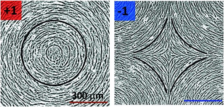
1. Introduction
The importance of nematic ordering in the alignment of living cells is gathering more evidence by the day. The idea that cell layers exhibit liquid crystal (LC) order dates back to the pioneering studies of Yves Bouligand on chitin shells,1 but in recent years the evidence of the connections between biology and liquid crystals has stimulated a resurgence of interest in the LC nature of cells. Cells confined onto 2-dimensional (2D) substrates arrange as nematic LCs2 characterized by a strong tendency of cells to align with their neighbors. This is very evident in the case of bacterial cells3 or of elongated cells such as fibroblasts or myoblasts.4–7 The LC behavior affects how a cell layer is organized and how forces are distributed and transmitted.
This is especially relevant near topological defects, regions where the nematic order is lost8,9 in order to minimize stresses in the ordered fluid. In LCs, one can think of defects as small isotropic regions in an ordered liquid. The disordered region is known as the defect core, and strong elastic distortions are concentrated around it. In 2D, defects are characterized by a topological charge, i.e. the angle by which LC mesogens rotate around the defect, divided by 2π.9 This quantity is additive, conserved, and determined by the topology of the LC confinement. For example, if nematic LCs are confined on the surface of a sphere, the total topological charge is +2 and it can be realized with an arbitrary number of defects whose charges add up to +2. In nematics, topological charge can be integer or semi integer, the most common defects being ±1/2 and ±1. Defects with the same topological charge may have different molecular arrangements around them, which depend on the energetic cost of various types of deformations. For example, around a topological defect with a charge of +1, LC molecules can have a radial arrangement with a large splay deformation or azimuthal arrangement with a large bend deformation, depending on which elastic distortions are energetically favorable. In common LCs, defects interact with each other strongly by elastic interactions, they are able to trap colloidal particles and small molecules,10–12 they exhibit interesting optical effects13,14 and in general they are mediators of self-assembly.15
Cell layers also form topological defects as they rearrange, and it is becoming evident that these defects have a biological role. Saw et al.16 found that near +1/2 defects the rate of apoptosis of MDCK epithelial cells is higher, due to the presence of isotropic compressive stresses. In contrast, the −1/2 defects are characterized by tensile stresses and do not trigger apoptosis. Kawaguchi et al.17 reported a strong effect of topological defects in murine neural progenitor cells moving on substrates without attaching. The density of the monolayer increases next to the +1/2 defects, eventually resulting in the formation of large cell conglomerates. Important effects of defects have been reported in bacterial systems, where the +1/2 defects drive the morphology of bacterial colonies,18 and where they are responsible for the initial formation of multi-layer structures.19
Defects with topological charge ±1/2 are commonly observed in cell cultures and have therefore been the subject of many studies. On the other hand, defects with integer charge ±1 are not typically observed in flat layers and have received less attention. However, these types of defects are still present in living systems in various forms. There are many examples of fibers forming topological defects with +1 charge, either with azimuthal or with radial alignment, such as those around the optic nerve20 and at the tumor-stromal interface.21,22 Furthermore, circular alignment is also seen in epithelial cells, forming rosettes,23 and circularly aligned clusters seem to precede tube invagination during embryogenesis.24 This behavior recalls that observed in small organisms such as hydra, where the formation of +1 defects is associated to the localization of the hydra's head and foot, thus playing an important role in determining the 3-dimensional shape.25
The control of cells through topography is relevant for the arrangement of cell orientation and subsequent tissue architecture, and thereby may be useful to guide desired tissue integration of implants in clinical applications, to restore normal physiological functions. It is well known that nano-sized topographical features such as grooves or ridges can align fibroblasts. The alignment strength depends on the width and height of the ridges. Turiv et al. recently explored the possibility to impose defects with integer charge in human dermal fibroblasts by using nano ridges caused by the swelling of liquid crystal elastomers in aqueous medium.26 They observed the spontaneous separation (unbinding) of the +1 defects into two defects with topological charge +1/2, confirming that defects with integer charge tend to be unfavorable in flat cell layers.
A different strategy for alignment relies on the use of larger features, such that the alignment does not rely solely on the interaction between the cells and the substrate but also on the spontaneous nematic alignment of the cells. Here, we use micron-sized topography to investigate the possibility to induce stable defects with topological charge +1 and −1 (Fig. 1a). The spacing of the ridges is on the scale of several cell sizes, so that the mechanism of cell alignment on the ridges is likely entropic.27 In this paper, we focus mainly on fibroblasts and epithelial cells, chosen as epitome of two different cell types: fibroblasts interact strongly with the substrate and are able to assume very anisotropic shapes; in contrast, the EpH-4 epithelial cells have strong cell–cell junctions and are quite isotropic in shape. Our patterns allow us to investigate situations where cells monolayers experience the frustration of undesired topological structures, thereby gathering information on the LC behavior of the cell layers.
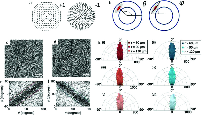
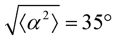
Fig. 1. Topological defects in fibroblasts. (a) Schematic of a +1 azimuthal and a −1 topological defect. (b) Schematic of θ, corresponding to the angle from the center of the defect, and ϕ, the angle of the major axis of the nucleus. (c) Phase contrast (PC) image of 3T6 cells in the vicinity of a positive defect on r = 120 μm pattern. Scale Bar is 120 μm. (d) PC of 3T6 in the vicinity of a negative defect on r = 120 μm pattern. Scale bar is 120 μm. The ridges are 1.5 μm tall. (e) Scatter plot of 3T6 alignment with r = 90 μm positive defect pattern. Red lines indicate root-mean-square (rms) deviation from the expected angle. The shades of red correspond to the colors specified in (g), indicating the  for all the patterns with different ridge spacing. In this case, they overlap. (f) Scatter plot of 3T6 alignment with r = 90 μm negative defect pattern. Blue lines indicate rms deviation in angle
  for all three patterns, corresponding to the shades in (g). Alignment of 3T6 with ridges for (i and ii) r = 60 μm, (iii and iv) r = 90 μm, and (v and vi) r = 120 μm patterns around (i, iii and v) positive defects and (ii, iv and vi) negative defects. Radial axis represents number of cells, and angle represents the deviation of cell alignment from the expected value. (i) has n = 5 samples, and
 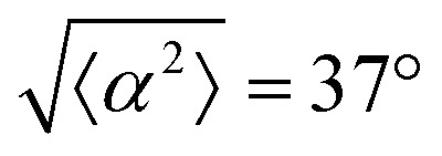 . (ii) has n = 5, and
 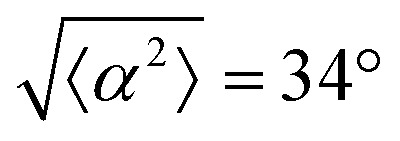 . (iii) has n = 7, and
 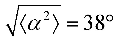 . (iv) has n = 5, and
 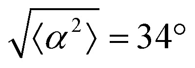 . (v) has n = 5, and
 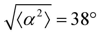 . (vi) has n = 5, and
  .
.
2. Results and discussion
We analyze the behavior of cells on polydimethylsiloxane (PDMS) patterns that create a square array of +1 and −1 defects. We vary the spacing between the +1 and −1 defects and the distance between the ridges of the pattern. The width of the ridges is 9 μm with a height ranging from 0.5 to 3 μm and the PDMS is covered with fibronectin to ensure a good adhesion of the cells. The details of the fabrication and surface treatments are reported in the Methods section. We vary the spacing between the ridges from 30 to 200 μm and the distance between the defects from 200 to 1200 μm. We study the behavior of 3T6 fibroblasts and EpH-4 epithelial cells. In particular, we focus on (i) the degree of alignment of cells on patterns, (ii) the distribution of cell density on the pattern, (iii) the compressive stresses near the defects, (iv) the configuration of cells in the proximity of topological defects.
Here we need to add a consideration on this system. It is known that ±1/2 topological defects form spontaneously and proliferate in active nematic systems. An increase in cell motility or myosin activity lead to an increase in the density of the defects which are spontaneously generated. We have verified that the number of defects is not altered by influencing the myosin activity. Blebbistatin is a myosin II inhibitor which decreases force generation; calyculin is a phosphatase inhibitor which increases force generation. By treating the cells on our pattern with these chemicals we have not detected a change in the number of defects. In fact, in all cases the cell monolayers form the minimal number of defects set by their boundary conditions. In virtue of this observation, in the present work we focus on the static configurations of cells.
2.1. Alignment on patterns
We observe 3T6 fibroblasts derived from albino mice on patterns where the spacing between ridges, r, is 60, 90 and 120 μm and the ridge height is 1.5 μm. The results are shown in Fig. 1, where we measure the angle of alignment of the cells with respect to their position relative to the defect (Fig. 1b). The angles are measured from the center of the topological defects. As expected, the fibroblasts follow the ridges (Fig. 1c and d), and they can align well on all three patterns. They show the expected orientation around the defect as shown in Fig. 1e and f, where every point of the diagram represents the orientation of one cell with respect to their nearest +1 or −1 defect, and the slope depends on the charge of the topological defect. The cell orientation is determined by staining the cells with cell-permeant nuclear stains (Hoechst 33342 and NucRed Live 647), fitting their nuclei shape to ellipses, and analyzing their orientation. Fig. 1g shows a similar angle distribution of the cells for every pattern, indicating that the level of alignment does not strongly depend on the distance between ridges.
The mechanism for cells’ alignment on ridges is a debated topic and several mechanisms concur to it. In our system, the cells closest to the ridges sense the edges of the features, or the curvature of the walls, and that this alignment is propagated to the other cells via nematic order. In addition to the varying spacing between ridges, we utilize different heights for the ridges, from 0.5 to 3 μm. As suggested by Bade et al.,28 cells need to rearrange their cytoskeleton in order to climb on higher features. Therefore we expect a change in alignment with the height of the ridges. The alignment of fibroblasts increases significantly from the 0.5 μm- to the 1.5 μm-tall ridges, but does not improve significantly from 1.5 to 3 μm ridges, as shown in ESI,† Fig. S1. We therefore decided to utilize 1.5 μm-tall ridges for most of our measurements.
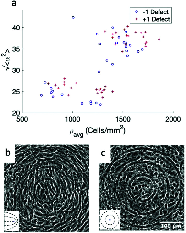
While the quality of the alignment of fibroblasts does not depend on the spacing between ridges, it shows a strong dependence on the average density of the cell monolayer, as shown in Fig. 2. We study the cases of monolayers ranging from 600 cells per mm2 corresponding to 60% confluency, to 2000 cells per mm2 corresponding to a tightly packed monolayer well above confluency. We estimate a 100% confluency at around 1000 cells per mm2. In Fig. 2, we quantify the degree of alignment by the root-mean-square deviation of the angle α, which measures the difference between the cell alignment and the perfect alignment around a defect. We can see that  increases for densely packed monolayers, and the behavior indicates a significant decrease in cell alignment above a density threshold around 1400 cells per mm2, both for +1 and −1 defects. This is significantly larger than the density at which the monolayer becomes confluent, but it coincides with the density value at which the cells become less elongated. Fig. 2b and c show cells near a +1 defect below and after the threshold density value, and a visible change in their aspect ratio and alignment.
Fig. 2. Density dependence of 3T6 alignment on r = 60 μm patterns with 1.5 μm tall ridges. (a) Angle  , measuring the deviation from the ideal alignment, as a function of the average density of cell monolayers. Every point corresponds to the observation of cells near one defect, either positive (red crosses) or negative (blue circles). (b) Details of fibroblasts near a positive defect in a monolayer with density 1400 cells per mm2, showing good alignment. (c) Detail of fibroblasts near a positive defect with density 1700 cells per mm2, showing a smaller aspect ratio and worse alignment. For n = 30 negative defects and n = 39 positive defects, we observe a difference in the quality of alignment between cells with a density typically >1400 cells per mm2 and with a density <1400 cells per mm2, with p-value < 0.0001.
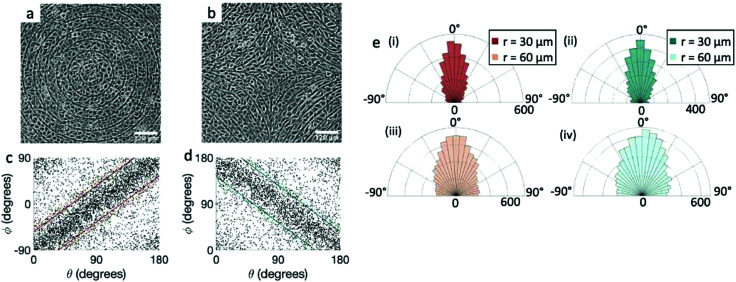
We perform the same experiment with EpH-4 epithelial cells (Fig. 3). If we use the same patterns used for the fibroblasts (r = 60 μm, Fig. 3a and b, or larger), the alignment observed in the cells is present, but much weaker. We then utilize a pattern with ridges which are more finely spaced, with 30 μm spacing, and indeed that gives a much better alignment to the epithelial cells, comparable to that of fibroblasts, as can be seen from the scatter plots in Fig. 3c and d and from the angle distribution in Fig. 3e. We notice, however, that the tighter confinement means that only 1–2 cells can fit in between adjacent ridges, indicating that cells can align only if each cell is in direct contact with the topographical features. We verify that the height of the ridges chosen for fibroblasts is also suitable for epithelial cells. In epithelial cells we again observe that the alignment improves with taller ridges, but ridges above 2 μm prevent the cells from going over them, as shown in ESI,† Fig. S2. Therefore we also favored the use of the 1.5 μm ridges for epithelial cells. Unlike the fibroblasts, the density of the monolayers does not affect the quality of alignment of epithelial cells, which do not significantly alter their aspect ratio as they increase in density. It should be noted, however, that once they reach confluency the epithelial cells stop dividing and die, unlike fibroblasts, where we are allowed to explore a higher range of density above confluency.
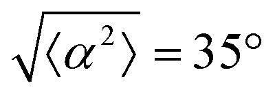
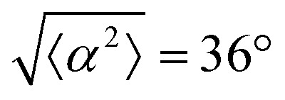
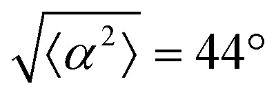
Fig. 3. Alignment of EpH-4 cells near topological defects. (a) PC of EpH-4 cells in the vicinity of a positive defect on r = 60 μm pattern. Scale bar is 120 μm. (b) PC of EpH-4 cells in the vicinity of a negative defect on r = 60 μm pattern. (c) Scatter plot of EpH-4 alignment with r = 30 μm positive defect pattern. Lines of different shades indicate  for r = 30 μm and r = 60 μm. (d) Scatter plot of EpH-4 alignment with r = 30 μm negative defect pattern. Lines of different shades indicate
  for r = 30 μm and r = 60 μm. (e) Alignment of EpH-4 with ridges of (i and ii) r = 30 μm and (iii and iv) r = 60 μm patterns around (i and iii) positive defects and (ii and iv) negative defects. (i) n = 4 samples and
  . (ii) has n = 3 and
  . (iii) has n = 5 and
  . (iv) has n = 5 and
 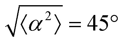 .
.
2.2. Cell density distribution
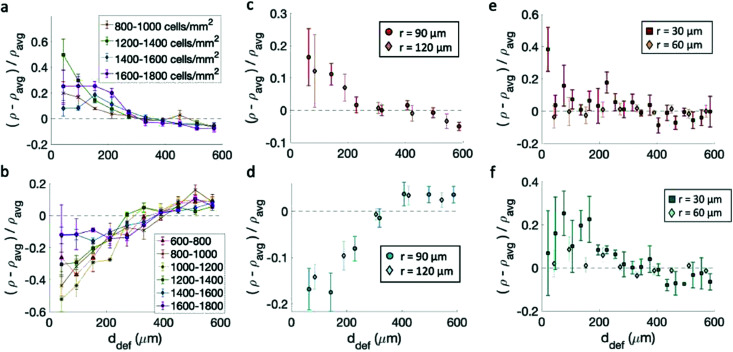
Having confirmed that the cells align on the patterns, we track the cell density ρ, defined as the number of cells per unit area, as a function of the distance from the center of the topological defects. We then consider the relative densities of the cells at various distances from the center of the defects, each normalized by the average sample density. In the case of fibroblasts, most data indicate that the density is maximum near the +1 defect and minimum near the −1 defects for all patterns (Fig. 4a–d). This is consistent with observations made on neural progenitor cells near +1/2 defects.17
Fig. 4. Density of cells near defects with positive and negative topological charge. (a and b) Density of fibroblasts near +1 (a) and −1 (b) defects for monolayers at different cell density on 60 μm-spaced, 1.5 μm-tall ridges. The legend indicates the density range in cells per mm2. Note that for (a) the cell density was calculated from the fluorescence intensity and not by nuclear counting, as discussed in the Methods section. (c and d) Density of fibroblasts as a function of distance from the defects +1 (c) and −1 (d) defects. The data refer to patterns with different sizes. (e and f) Density of epithelial cells near +1 (e) and −1 (f) defects. All densities are normalized by the average density of each pattern. Statistical analysis of this figure are reported in Methods. Briefly, an increase in cell density is observed within 200 μm of a +1 defect with a p-value <0.05 for cells at all densities in (a), the 90 μm pattern in (c), and the 30 μm pattern in (e). A decrease in cell density is observed within 200 μm of a −1 defect with p-values < 0.05 for cells at densities < 1600 cells per mm2 in (b), both patterns in (d), and the 30 μm pattern in (f).
Cell density, however, plays a role in determining the relative increase/decrease of density near the +1/−1 defects for fibroblasts. The inhomogeneity in the cell density is maximum when the cell alignment is the highest. Fig. 4a and b shows the density variation for monolayers at various densities. The behavior is non-monotonic. At low density, the monolayer shows more homogeneity in density. When the monolayer reaches confluency the inhomogeneity is maximum, with defects densely packed near +1 defects and loosely packed near −1 defects. The comparison with Fig. 2 suggest that once the aspect ratio of cells starts to change, and the alignment quality decreases, the monolayer becomes more homogeneous and the difference between +1 and −1 defects is reduced, although never entirely suppressed. On the other hand, the spacing between ridges does not significantly affect the density variation, as suggested by Fig. 4c and d, not even where high-density monolayers are created on ridges with larger spacing. Preliminary data also suggest that seeding density may influence the packing, and cells planted initially at density above 20 × 104 cells per mL cannot achieve an ordered packing near the defects. In our work, we have used cells at low seeding density to ensure that they had time to align as they reach confluency.
The case is different for epithelial cells, which only show a slight increase of density near both defects of positive and negative charge (Fig. 4e and f). Also in this case the difference is more marked for the finely spaced pattern. Consistently, the work of Saw et al.16 showed an increase of apoptosis near +1/2 defects not correlated with an increase in cell density of epithelial cells. For EpH-4 cells, we could not observe any difference in the density distribution as a function of cell density.
2.3. Forces and dynamics
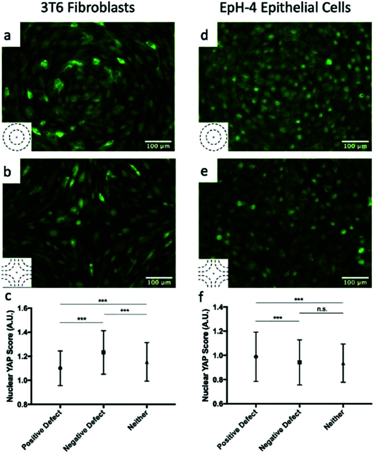
The high density of fibroblasts near +1 defects and the low density near −1 defects bears similarity to the conglomerates observed by Kawaguchi et al.17 in neural progenitor cells near +1/2 defects. However, there are important differences between the two systems: first, fibroblasts move much more slowly than neural progenitor cells and the system is dominated by friction; secondly, the nematic director of cells near +1 defects have a central symmetry that the director around +1/2 defects lack. The work of Saw et al. on epithelial cells suggests that compressive stresses are key in determining the different behavior of cells near defects.16 We analyzed the distribution of the apoptosis inhibitor yes-associated proten (YAP) near +1 and −1 defects for fibroblasts and epithelial cells. YAP is mechanosensitive and translocates from the nucleus to the cytoplasm when cells are subjected to mechanical strain such as compression.29,30 In fibroblasts, near +1 defects, YAP is more localized in the cell cytoplasm, suggesting the presence of mechanical strain. On the other hand, cells near −1 defects have YAP localized in nuclei. This is shown in Fig. 5a and b and on the left-hand side of Fig. 5c, where the mean nuclear YAP score, which is the ratio of nuclear to cytoplasmic YAP intensity, is shown for the cells near the defects and far from them. The source of the compressive stress might be from the cell–cell interaction near the +1 defect. Further characterization of interaction between cells near defects is a promising route for future understanding. In epithelial cells, the data show an increase in nuclear YAP near +1 defects on r = 60 μm patterns (Fig. 5d and f), similarly to the observations reported in ref. 16 for +1/2 defects. On the other hand, we do not observe a significant decrease in nuclear YAP near −1 defects.
Fig. 5. YAP localization in cells. (a and b) Fluorescence images showing YAP localization in 3T6 cells on r = 120 μm patterns indicates the presence of compressive stresses. In +1 defects, YAP is mostly localized in cytoplasm (a), while in −1 defects it is localized in nuclei (b). The ratio of nuclear to cytoplasmic YAP is shown in panel (c) for 3T6 cells near +1 defects, near −1 defects and far from defects. (d and e) Fluorescence images showing YAP localization in EpH-4 cells on r = 60 μm patterns near +1 defects, where it is localized in nuclei (d), and −1 defects, where it is more evenly distributed (e). The ratio of nuclear to cytoplasmic YAP is shown in panel (f) for EpH-4 cells near +1 defects, near −1 defects, and far from defects. Insets indicate the type of defect in the corresponding images. For each defect, at least n = 4 samples were included in analysis; error bars represent standard deviation; *** indicates p-value < 0.0001, n.s. is for “not significant”.
2.4. Cells near the defect core
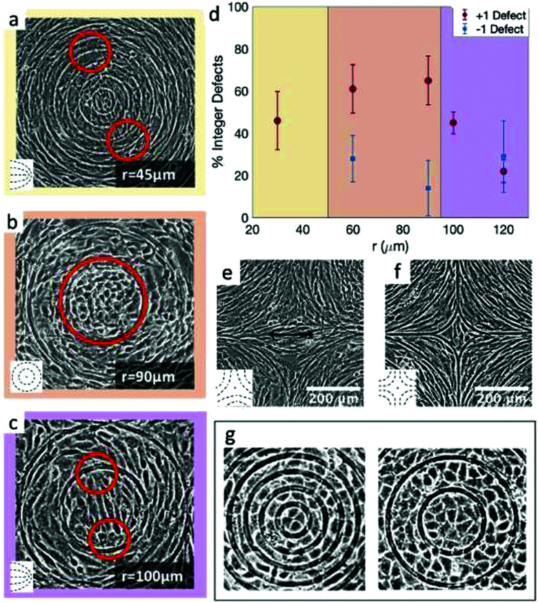
The results shown in Fig. 4 lead to two conclusions: that the behavior of fibroblasts depends on the charge of the defects and that the lengthscale of the pattern is relevant. To understand this, we inspect more closely what happens in the inner region near the defects. Typical results for positive defects are shown in Fig. 6a–c, which show cells near defects on patterns with increasing spacing between ridges. If the inner circle has a radius above 100 μm, the cells tend to arrange in a configuration with two +1/2 defects near the edges of the circle (Fig. 6c). This was also shown in ref. 6 and 7 where the fibroblasts were confined in round patches with radii of a few hundred microns. The ESI,† Video V1 shows this symmetry breaking process, occurring when cells are at low density and choose one direction of alignment in the center. However, if the radius of the inner circle is reduced, the cells can adopt a different configuration: the cell shape becomes more symmetric and the cells pack isotropically (Fig. 6b). Essentially, the cells stop being LC mesogens by changing their shape from elongated to round. This isotropic region is surrounded by elongated cells with entirely azimuthal alignment. We therefore identify this as a true +1 topological defect in the cell monolayers. The graph in Fig. 6d shows the relative prevalence of the +1 defect with respect to the two +1/2 defects as a function of the radius of the inner ring. It is immediately noticeable that the fraction of +1 defects has a maximum for radii around 60–80 μm but is lower at smaller radii. The alignment cues from the ridges have negligible effects when the cells are too tightly confined. Instead, the cells form two +1/2 defects at a larger distance, as shown in Fig. 6a and in ESI,† Video V2. This can be altered by using taller ridges, so that cells are imposed with a higher energy barrier to overcome the ridges. In this case, isotropic packing of cells is seen also with smaller confining inner ridges. To our knowledge, this behavior has not observed in other cell systems: in fact, typically either the +1 defect unbinds into two +1/2 defects, as in ref. 6 and 26, or the cells create vortex-like structure or are extruded, as shown in ref. 31 for myoblasts. Our platform allows us to probe this configuration for 3T6 due to carefully tunable boundaries.
Fig. 6. Examples of cell alignment near the positive and negative defects. (a) 3T6 fibroblasts with defect splitting into two +1/2 defects far from the inner ring, (b) isotropic region in the inner ring, indicating a +1 defect, and (c) defect splitting into two +1/2 defects in the inner ring. (d) Fraction of observed integer defects (as opposed to two half-integer defects), both for positive and for negative defects. Comparing r = 60 μm patterns (n = 18 samples) to r = 120 μm patterns (n = 60 samples), the prevalence of +1 defects was higher for the 60 μm pattern (p-value = 0.0015). (e and f) Cells near −1 defects with an elongated (e) or more isotropic (f) conformation. Insets display the type of defects observed in the cell alignment. (g) Rosette structure near +1 defects in EpH-4 epithelial cells in patterns by 30 and 60 μm.
Moreover, this behavior does not change by altering the distance between the patterned defects, if the defects are more than 100 μm apart. We probe this by reducing the number of topographical cues. For this, we use a pattern with only one or two ridges per circle (ESI,† Fig. S3). If the radius of the circular ridge is smaller than about 40 μm, fibroblasts ignore the topographical cues and grow all over the ridges, showing random +1/2 and −1/2 defects (ESI,† Fig. S3a). If the radii are between 100 and 200 μm or larger, the results are like those shown in Fig. 6. In that case, we observe the two possible configurations for the defect within the inner ring (one +1 or two +1/2 defects) and the splitting of the −1 defects into two defects (ESI,† Fig. S3b). If the separation between ridges is larger, fibroblast monolayers will form additional topological defects with charge +1/2 and −1/2 (ESI,† Fig. S3c).
Fibroblasts near defects with charge −1 do not pack densely near it, and consequently we observe fewer cells, especially for the more finely spaced ridges. However, the negative defects split into two −1/2 defects in the vast majority of cases (Fig. 6d and e), for all ridge spacing. A more isotropic packing of cells in the center, with elongated cells around it that follow the hyperbolic alignment, is observed in relatively few cases (Fig. 6f) and we call this configuration a −1 defect. There are two reasons for the prevalence of −1/2 defects: first, fibroblasts are less compressed near negative defects compared to positive defects, thereby they adopt the default fibroblast morphology of an elongated spindle; secondly, the region of the negative defect has a four-fold symmetry. As fibroblasts are elongated, they can easily align along the two alternative axes of symmetry of the defect, and this provides a natural way to “split” the defect into two −1/2 defects.
The case is different for epithelial cells. The alignment of cells is not greatly perturbed in the inner regions of the defects. For +1 defects, in the 30 μm patterns only few cells can fit in the inner circle, and they are always arranged isotropically, in the default cuboidal morphology of epithelial cells. We do not see the tendency we saw in fibroblasts, i.e. the formation of two +1/2 defects near the outer ridges. As we increase the size of the inner circle to a radius of 60 μm, epithelial cells are still isotropic (Fig. 6g). However, we observe either a slight symmetry breaking along an axis in the inner circle or a rosette-like structure, with cells arranged in roughly concentric rings and with central cells meeting at a single vertex, as shown in Fig. 6g. Increasing the size of the inner circle to 100 μm radius, the behavior remains similar to the 60 μm case.
2.5. Significance
The results presented above allow us to characterize some properties of the LC properties of cell monolayers. First, the dependence of alignment on fibroblast density and the different degree of alignment of epithelial cells all show that the aspect ratio of the cells is key in determining their ability to align nematically. Furthermore, this work shows a different density distribution of cells near and far from defects, which also depends on the cell anisotropy. The results mirror those obtained in neural progenitor cells,17 which showed a density increase near +1/2 defects and decrease near −1/2. Also the work by ref. 26, consistently with the observation of fibroblasts in this work, showed an increase in cell density near defects with charge +1 and a decrease near defects with charge −1. However, in their observations, human dermal Fibroblasts (HDF) near +1 defects always split into two +1/2 defects, and the distance between the defects allowed for an elegant estimate of several LC parameters. In our system, complementarily, the micron-sized ridges provide a stronger confinement and they allow for the direct observation of the isotropic arrangement of cells in the +1 defect (Fig. 6).
The data presented in our study provide further insight on the nature of the topological defects in cell systems. The search for the so-called core of a topological defect is very challenging in thermotropic LCs, mostly studied with theoretical models and computer simulations.32,33 In typical thermotropic LCs, this size is a few tens of nanometers, corresponding to about 10 times the molecular size. Defect core is usually defined as an isotropic region within the ordered fluid, even though studies in chromonics and other lyotropic LCs, where the core size is larger, have revealed a more complex alignment even inside the core of the defect.34,35
In our experiments, fibroblasts 3T6 have one more degree of freedom: due to the weak cell–cell adhesion strength, they can easily shift their morphology from elongated spindle to isotropic cuboid, no longer acting as mesogens in the core of the defect. This behavior leads us to identify a length-scale associated with this truly isotropic core, whose linear size is around 150–200 μm, corresponding to about 10 cells, in analogy with other LC systems. We can therefore start characterizing the core size as this length-scale where the transition takes place. While the unique shape-changing behavior of the fibroblasts allowed us to identify this length scale, these features were not observed for EpH-4 epithelial cells, most likely because the combination of their smaller aspect ratio and their strong cell–cell adhesion reduce the cells' ability to adjust density and shift between different shapes.
3. Conclusions
We have characterized the behavior of epithelial cells and fibroblasts on micron-sized topographical patterns that are imposing defects of integer topological charge, not easily observed in cell monolayers. Importantly, the topographical patterns are not insurmountable barriers, but gently confining shallow ridges, which can be easily overcome by the cells. While both cell types show alignment with the ridges, the alignment is much greater in fibroblasts. Fibroblasts also show an increase of density near defects with positive charge and a decrease near defects with negative charge. This behavior is strongly dependent on the density of the cell monolayer. The fibroblasts show a new behavior near defects with charge +1: if they are confined to a lengthscale around 150–200 μm, they lose their characteristic elongated shape and they become round, giving rise to a truly isotropic disordered defect core. The platform developed in our work provides the accessible system for such future studies.
Our studies are a characterization of the behavior of cells near defects of topological charge ±1, which are hard to see in monolayers without confinement, but are observable in living systems near protrusions or along aligned fibers. There is increasing evidence not only that topological defects affect cell behavior, but also that the effects are dependent on the topological charge. We envision our work raises the awarenes of the complex nature of cells in forming defects and inspires more detailed studies and hypotheses development to understand the liquid crystal behavior in cells as sophisticated interplay between biological elements of the cells and the physical conditions imposed externally.
4. Methods
4.1. Cell lines and culture methods
We used 3T6 fibroblasts and EpH4 epithelial cells. Cells were cultured in CellTreat Tissue Culture Dishes using 90% DMEM and 10% FBS. Cells were simultaneously growing on regular Petri dishes to verify that their growth and behavior was regular and healthy.
4.2. PDMS preparation
We prepared polydimethylsiloxane (PDMS) substrates with 15% curing agent. Once mixed with the curing agent, PDMS was degassed with vacuum at room temperature for 20 minutes. We then poured the PDMS over the SU8 patterned substrates. These were left in a vacuum oven between 35–50 °C overnight, then for 1 hour at 80 °C to finish curing. The patterned PDMS was then prepared for cell culture. The quality of the patterns was checked with an optical microscope and the height of the ridges was measured by cutting off a cross-section of the pattern (ESI,† Fig. S4).
4.3. PDMS preparation for cell culture
We sterilized the patterned PDMS by submerging it in ethanol for 20 minutes. Then we washed the substrates with a balanced salt solution (PBS). Fibronectin was added to the substrates as an attachment factor at 25 μg mL−1. The substrates were coated with minimal volume for 45 minutes and washed with PBS prior to use for cell culture.
4.4. Staining and imaging cells
The cells were stained using either of two cell-permeant nuclear stains: Hoechst 33258 dye (10 mg mL−1 stock solution purchased from Invitrogen) and NucRed Live 647 ReadyProbes Reagent (purchased from ThermoFisher). The Hoechst solution was diluted at a ratio of 1 : 1000 in PBS, and cells were coated with this and placed in an incubator for 15 minutes. Then the dye was removed and washed away with PDMS, and the cells were ready to image. For the NucRed stain, 20 drops were added to the 10 mL of media in which the cells were growing, followed by 15 minutes in the incubator. Imaging was performed with an inverted microscope Nikon Ti-Eclipse, equipped with a Hamamatsu Orca-flash camera. At each location, two images were taken, one in phase contrast and the other with a fluorescent filter compatible with the nuclear stain.
4.5. Quantifying orientation of cells
The phase contrast image was used to locate the topographic features. From the phase contrast image, the center of each ring was identified using ImageJ and used to define the location of a +1 topological defect. The location of a −1 defect was defined by the center point between four surrounding +1 defects.
The orientation of nuclei was used as a proxy for the cell orientation. In order to quantify the orientation of the nuclei, we used ImageJ to first create a binary mask which showed contained only the cell nuclei, minimizing background features as much as possible. The watershed method was used to separate nuclei which appeared too close to each other to be distinguished in the image. The Fit Ellipse function in ImageJ was used to determine the center locations, major and minor axis lengths, major axis orientations, and areas of each nucleus. Cutoffs for the number of pixels for ellipses were chosen to have a sufficient signal level to background noise.
However, counting cell nuclei with fluorescence leads to under-estimating the number of cells in the very high density region as shown in ESI,† Fig. S5. For this reason, we have utilized a different method to analyze the density distribution near +1 defects for fibroblasts, where instead of counting nuclei we integrate the fluorescent intensity over concentric rings at various distances from the defect. At low density, however, cell counting is a more accurate method, as the fluorescence signal in those regions is lower and tends to underestimate the inhomogeneities. All this is discussed in Fig. S5 (ESI†).
The angle from the center of the defect was determined based on the location of the center of the defect defined from the phase contrast image and the location of the center of the nucleus given by the ellipse fitting. We verified the accuracy of this method at low cell density comparing it with an analysis of cell shapes from FogBank as explained in ESI,† Fig. S6.
4.6. Observing YAP localization in cells
Upon reaching confluence, cells were fixed in 4% paraformaldehyde, and then stained with YAP1 primary antibody (Novus Biologics, Cat. No. NB110-58358), and AlexaFluor 488 Goat anti-Rabbit secondary (Jackson ImmunoResearch, Cat. No. 111-545-144). The nuclei were then stained with DAPI.
Analysis of YAP localization was performed as in ref. 29. Briefly, the nucleus of each cell was segmented using the DAPI channel, and the average intensity of YAP was measured inside the nucleus and just outside the nucleus. The nuclear YAP score was then obtained by taking the ratio of nuclear to cytoplasmic YAP mean intensity.
Statistical analysis was done in Prism using Ordinary one-way ANOVA with Tukey's test for multiple comparisons. For each defect, a minimum of 4 samples and 6 samples were analyzed for 3T6 and EpH4, respectively.
4.7. Varying activity of cells
To suppress actomyosin activity, cells were treated with blebbistatin (Toronto Research Chemicals, Cat. No. B592500). We diluted the blebbistatin to a 50 μm concentration in DMEM, and added the mixture to the confluent cells on the topographic patterns after sonicating for 10 minutes. After incubating for 6 hours, the blebbistatin was removed, and the cells were washed three times with 5 mL PBS. The media was replaced with CO2 Independent Medium (ThermoFisher Scientific) mixed with 10% FBS and 4.05 g L−1l-glutamine (Quality Biological). The cells were then imaged at 37 °C every minute for 12 hours using the phase contrast microscope.
To enhance actomyosin activity, cells were treated with Calyculin-A (Cell Signaling Technology, Cat. No. 9902). We diluted the Calyculin-A in DMEM to a 50 nM concentration, and added the mixture to confluent cells on the topographic patterns after sonicating for 15 minutes. Before Calyculin treatment, cells were stained with Hoechst 33258 dye at a 1 : 2000 dilution and incubated for 15 minutes, after which the samples were washed with PBS. The cells were then incubated with the Calyculin mixture for 30 minutes, after which it was removed and the samples were washed three times with 5 mL PBS. The cells were imaged at 37 °C in CO2 independent media (same mixture used for blebbistatin treatment).
4.8. Statistical analysis
The degree of cell alignment with the pattern was determined by comparing ϕ to the expected angle which, in the case of the +1 azimuthal defect pattern, was defined as θ + 90, while for the −1 defect pattern, the expected angle is equal to 180 − θ. The deviation from the expected angle we call α, and to quantify the overall alignment of cells we compute  .
.
The uncertainty reported in the observed variations from the average density was reported as the standard error of the mean (SEM). We performed t-tests using Matlab to test the null hypothesis: H0: the average density of cells within 200 μm of a +1/−1 topological defect is the same as the average density of all the cells within 600 μm of the +1/−1 defect. H1: the average density is greater/lower within 200 μm of a +1/−1 defect than the average density of cells within 600 μm of the +1/−1 defect.
For Fig. 4a, n = 5 samples were observed in each reported density range. For 800–1000 cells per mm2, a p-value of 0.02 was obtained for observing a density increase within 200 μm of the center; for 1200–1400 cells per mm2, p-value = 0.0015; for 1400–1600 cells per mm2, p-value = 0.02; for 1600–1800 cells per mm2, p-value = 0.002.
For Fig. 4b: for 600–800 cells per mm2, n = 4 samples were observed, with a p-value of 0.015 for the observing a density decrease within 200 μm of the center; for 800–1000 cells per mm2, n = 3 and p-value = 0.04; for 1000–1200 cells per mm2, n = 4 and p-value = 0.002; for 1200–1400 cells per mm2, n = 8 and p-value < 0.0001; for 1400–1600 cells per mm2, n = 10 and p-value < 0.0001; for 1600–1800 cells per mm2, n = 2 and p-value = 0.18, meaning that we cannot reject H0 only for this high density range.
For Fig. 4c: on the r = 90 μm patterns, n = 7 and p-value = 0.046; on the r = 120 μm patterns, n = 5 and p-value = 0.25. Therefore we cannot reject H0 on the pattern alone. However, a p-value of 0.018 is obtained for both pattern sizes combined, which we determined to be appropriate given that the fibroblasts obtained similar alignment on both pattern types.
For Fig. 4d: on the r = 90 μm patterns, n = 5 and p-value = 0.003; on the r = 120 μm patterns, n = 5 and p-values = 0.013; combined, a p-value < 0.0001 was obtained.
For Fig. 4e: on the r = 30 μm patterns, n − 4 samples were observed, and a density increase within 200 μm of the center of the +1 defect was observed, with a p-value = 0.026; on the r = 60 μm pattern, n = 5 and p-value = 0.97. For Fig. 4f: on the r = 30 μm patterns, n = 3 and p-value = 0.004; on the r = 60 μm patterns, n = 5 and p-value = 0.18. Therefore, we cannot reject H0 for the r = 60 μm patterns for EpH-4 cells.
The uncertainty in the defect prevalence is the uncertainty in a binomial distribution,  . To determine the statistical significance between the binomial distribution for two different feature sizes, the following formula was used to obtain the test statistic, which was then used for a two-tailed t-test:
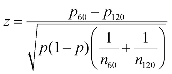 where p is the combined probability of an integer defect on either pattern.
For the +1 defect prevalence shown in Fig. 6d, at r = 30 μm, 13 samples were observed; at r = 60 μm, 18 samples were observed; at r = 90 μm, 17 samples were observed; at r = 100 μm, 93 samples were observed; at r = 120 μm, 60 samples were observed.
For the −1 defect prevalence shown in Fig. 6d, at r = 60 μm, 18 samples were observed; at r = 90 μm, 7 samples were observed; at r = 120 μm, 7 samples were observed.
Conflicts of interest
There are no conflicts to declare.
Supplementary Material
Acknowledgments
The authors would like to thank Colin Bilyeu for his help with experiments. This material is based upon work supported by the National Science Foundation Graduate Research Fellowship under Grant No. DGE-1746891 awarded to K. D. E. Research reported in this publication was supported by the National Institute of Biomedical Imaging and Bioengineering (NHBIB) of the National Institutes of Health under award number R21EB029677 awarded to Y.C, and by the NHLBI Ruth L. Kirschstein National Research Service Fellowship number F31HL154709-01 awarded to M.P. The content is solely the responsibility of the authors and does not necessarily represent the official views of the National Institutes of Health.
Electronic supplementary information (ESI) available. See DOI: 10.1039/d1sm00100k
Notes and references
- Bouligand Y. C. R. Chim. 2008;11:281–296. doi: 10.1016/j.crci.2007.10.001. [DOI] [Google Scholar]
- Saw T. B. Xi W. Ladoux B. Lim C. T. Adv. Mater. 2018;30:1802579. doi: 10.1002/adma.201802579. [DOI] [PubMed] [Google Scholar]
- Volfson D. Cookson S. Hasty J. Tsimring L. S. Proc. Natl. Acad. Sci. U. S. A. 2008;105:15346–15351. doi: 10.1073/pnas.0706805105. [DOI] [PMC free article] [PubMed] [Google Scholar]
- Li X. Balagam R. He T.-F. Lee P. P. Igoshin O. A. Levine H. Proc. Natl. Acad. Sci. U. S. A. 2017;114:8974–8979. doi: 10.1073/pnas.1707210114. [DOI] [PMC free article] [PubMed] [Google Scholar]
- Martella D. Pattelli L. Matassini C. Ridi F. Bonini M. Paoli P. Baglioni P. Wiersma D. S. Parmeggiani C. Adv. Healthcare Mater. 2019;8:1801489. doi: 10.1002/adhm.201801489. [DOI] [PubMed] [Google Scholar]
- Duclos G. Garcia S. Yevick H. Silberzan P. Soft Matter. 2014;10:2346–2353. doi: 10.1039/C3SM52323C. [DOI] [PubMed] [Google Scholar]
- Duclos G. Erlenkämper C. Joanny J.-F. Silberzan P. Nat. Phys. 2017;13:58. [Google Scholar]
- Chandrasekhar S. Ranganath G. Adv. Phys. 1986;35:507–596. doi: 10.1080/00018738600101941. [DOI] [Google Scholar]
- Kleman M. Lavrentovich O. D. Philos. Mag. 2006;86:4117–4137. doi: 10.1080/14786430600593016. [DOI] [Google Scholar]
- Blanc C. Coursault D. Lacaze E. Liq. Cryst. Rev. 2013;1:83–109. doi: 10.1080/21680396.2013.818515. [DOI] [Google Scholar]
- Wang X. Miller D. S. Bukusoglu E. De Pablo J. J. Abbott N. L. Nat. Mater. 2016;15:106. doi: 10.1038/nmat4421. [DOI] [PMC free article] [PubMed] [Google Scholar]
- Senyuk B. Evans J. S. Ackerman P. J. Lee T. Manna P. Vigderman L. Zubarev E. R. van de Lagemaat J. Smalyukh I. I. Nano Lett. 2012;12:955–963. doi: 10.1021/nl204030t. [DOI] [PubMed] [Google Scholar]
- Serra F. Gharbi M. A. Luo Y. Liu I. B. Bade N. D. Kamien R. D. Yang S. Stebe K. J. Adv. Opt. Mater. 2015;3:1287–1292. doi: 10.1002/adom.201500153. [DOI] [Google Scholar]
- Brasselet E. Phys. Rev. Lett. 2012;108:087801. doi: 10.1103/PhysRevLett.108.087801. [DOI] [PubMed] [Google Scholar]
- Muševič I. Škarabot M. Tkalec U. Ravnik M. Žumer S. Science. 2006;313:954–958. doi: 10.1126/science.1129660. [DOI] [PubMed] [Google Scholar]
- Saw T. B. Doostmohammadi A. Nier V. Kocgozlu L. Thampi S. Toyama Y. Marcq P. Lim C. T. Yeomans J. M. Ladoux B. Nature. 2017;544:212. doi: 10.1038/nature21718. [DOI] [PMC free article] [PubMed] [Google Scholar]
- Kawaguchi K. Kageyama R. Sano M. Nature. 2017;545:327. doi: 10.1038/nature22321. [DOI] [PubMed] [Google Scholar]
- Doostmohammadi A. Thampi S. P. Yeomans J. M. Phys. Rev. Lett. 2016;117:048102. doi: 10.1103/PhysRevLett.117.048102. [DOI] [PubMed] [Google Scholar]
- Copenhagen K. Alert R. Wingreen N. S. Shaevitz J. W. Nat. Phys. 2021;17:211–215. [Google Scholar]
- Gogola A. Jan N.-J. Lathrop K. L. Sigal I. A. Invest. Ophth. Vis. Sci. 2018;59:4763–4774. doi: 10.1167/iovs.18-25025. [DOI] [PMC free article] [PubMed] [Google Scholar]
- Provenzano P. P. Eliceiri K. W. Campbell J. M. Inman D. R. White J. G. Keely P. J. BMC Med. 2006;4:38. doi: 10.1186/1741-7015-4-38. [DOI] [PMC free article] [PubMed] [Google Scholar]
- Jung W.-H. Yam N. Chen C.-C. Elawad K. Hu B. Chen Y. Biomaterials. 2020;234:119756. doi: 10.1016/j.biomaterials.2020.119756. [DOI] [PubMed] [Google Scholar]
- Harding M. J. McGraw H. F. Nechiporuk A. Development. 2014;141:2549. doi: 10.1242/dev.101444. [DOI] [PMC free article] [PubMed] [Google Scholar]
- Sanchez-Corrales Y. E. Blanchard G. B. Roeper K. eLife. 2018;7:e35717. doi: 10.7554/eLife.35717. [DOI] [PMC free article] [PubMed] [Google Scholar]
- Maroudas-Sacks Y. Garion L. Shani-Zerbib L. Livshits A. Braun E. Keren K. Nat. Phys. 2021;17:251–259. [Google Scholar]
- Turiv T. Krieger J. Babakhanova G. Yu H. Shiyanovskii S. V. Wei Q.-W. Kim M.-H. Lavrentovich O. D. Sci. Adv. 2020;6:eaaz6485. doi: 10.1126/sciadv.aaz6485. [DOI] [PMC free article] [PubMed] [Google Scholar]
- Buskermolen A. B. C. Suresh H. Shishvan S. S. Vigliotti A. DeSimone A. Kurniawan N. A. Bouten V. C. Deshpande V. S. Biophys. J. 2019;116:1994. doi: 10.1016/j.bpj.2019.04.003. [DOI] [PMC free article] [PubMed] [Google Scholar]
- Bade N. D. Xu T. Kamien R. D. Assoian R. K. Stebe K. J. Biophys. J. 2018;114:1467–1476. doi: 10.1016/j.bpj.2018.01.039. [DOI] [PMC free article] [PubMed] [Google Scholar]
- Das A. Fischer R. S. Pan D. Waterman C. M. J. Biol. Chem. 2020;291:6096. doi: 10.1074/jbc.M115.708313. [DOI] [PMC free article] [PubMed] [Google Scholar]
- Zou R. Xu Y. Shen M. Yuan F. Yuan Y. Cell. Biol. Inter. 2020;44:1416. doi: 10.1002/cbin.11345. [DOI] [PubMed] [Google Scholar]
- Guillamat P. Blanch-Mercader C. Kruse K. Roux A. Bioarxiv. 2020 doi: 10.1101/2020.06.02.129262. [DOI] [Google Scholar]
- Schopohl N. Sluckin T. J. Phys. Rev. Lett. 1987;59:2582–2584. doi: 10.1103/PhysRevLett.59.2582. [DOI] [PubMed] [Google Scholar]
- De Luca G. Rey A. D. J. Chem. Phys. 2007;126:094907. doi: 10.1063/1.2711436. [DOI] [PubMed] [Google Scholar]
- Zhou S. Shiyanovskii S. Park H.-S. Lavrentovich O. D. Nat. Commun. 2017;8:14974. doi: 10.1038/ncomms14974. [DOI] [PMC free article] [PubMed] [Google Scholar]
- Zasadzinski J. A. N. Meyer R. B. Phys. Rev. Lett. 1986;56:636–638. doi: 10.1103/PhysRevLett.56.636. [DOI] [PubMed] [Google Scholar]
Associated Data
This section collects any data citations, data availability statements, or supplementary materials included in this article.


