

Abstract
Objective:
This study aimed to develop a unique exoskeleton to provide different types of elastic resistances (i.e., resisting flexion, extension, or bidirectionally) to the leg muscles during walking.
Methods:
We created a completely passive leg exoskeleton, consisting of counteracting springs, pulleys, and clutches, to provide different types of elastic resistance to the knee. We first used a benchtop setting to calibrate the springs and validate the resistive capabilities of the device. We then tested the device’s ability to alter gait mechanics, muscle activation, and kinematic aftereffects when walking on a treadmill under the three resistance types.
Results:
Benchtop testing indicated that the device provided a nearly linear torque profile and could be accurately configured to alter the angle where the spring system was undeformed (i.e., the resting position). Treadmill testing indicated the device could specifically target knee flexors, extensors, or both, and increase eccentric loading at the joint. Additionally, these resistance types elicited different kinematic aftereffects that could be used to target user-specific spatiotemporal gait deficits.
Conclusion:
These results indicate that the elastic device can provide various types of targeted resistance training during walking.
Significance:
The proposed elastic device can provide a diverse set of resistance types that could potentially address user-specific muscle weaknesses and gait deficits through functional resistance training.
Index Terms—: Design, Electromyography, Kinetics, Task-specific, Therapy, Robotic
I. INTRODUCTION
GAIT impairments are a prominent source of disability after neurological or orthopedic injuries [1–4]. For example, following a stroke—which is the leading cause of long-term disability in the United States [5]—only 50% of survivors are able to ambulate in the community following conventional therapy [6]. Such impairment can greatly affect independence and quality of life [7]; hence, retraining gait following an injury is of the utmost importance. Applying functional resistance training during walking is an emerging method for treating individuals with gait impairments. This training is administered by having a patient perform a task-specific training (in this case, walking) while a load is applied to resist the movement [8–10]. This works simultaneously to improve muscle strength and coordination, which are often underlying sources of gait impairment [11–13].
Most studies have applied functional resistance training using simple rehabilitation equipment, such as ankle weights [14–17]. While these devices are low-cost and widely available in clinics, they are limited in their ability to target patient-specific muscle weakness during walking. This is because the load is tethered to the user’s ankle (i.e., the distal end of the shank); hence, resistance is automatically coupled between the user’s hip and knee joints [18]. This problem can be remedied by devices that directly resist the motion of the joint (i.e., a joint-space approach). Joint-space based devices include wearable leg braces and exoskeletons and allow resistance to be targeted to a single joint if desired. This is potentially beneficial for rehabilitation, as therapists often measure strength at the joint level using clinical tests (e.g., manual muscle testing) or dynamometry [19]. Hence, joint-space based devices can directly target these patient specific weaknesses while providing resistance during functional tasks. For this reason, there have been several joint-space devices developed in recent years for providing functional resistance training during walking [8, 20–25].
While all of these devices apply resistance in the joint space, they differ in the type of resistance that they are designed to provide. For example, a majority of these devices provide viscous loads to the participant during walking [8, 21, 23]), meaning their resistance is proportional and opposite the velocity of the joint (i.e. a negative power constraint). While there are several benefits to viscous resistances [26]—such as the ease of use, smoothness, and controllability of the device—this negative power constraint also means that this strategy can only target muscles during concentric contractions (i.e. the muscle shortens while in tension). This is a potential limitation, as many key elements of walking rely on eccentric loading (i.e. muscle lengthening while in tension). For example, the hamstrings work eccentrically to slow knee extension in preparation for heel-strike; however, viscous devices cannot provide this type of resistance. To study these potential resistive paradigms, we will need to develop strategies that can remove the negative power constraint by allowing energy to be exerted on the user.
The type of actuator used to generate resistance determines whether a device can exert energy on the user. Most rehabilitation robots use active actuators (e.g., motors), which add external energy to the user in order to provide resistance. However, active actuators are typically expensive, bulky, and potentially unsafe if not programmed correctly. These issues can be addressed by using passive actuators (e.g., masses, springs, and dampers), which are relatively cost-effective, light-weight, and inherently safe, as they do not add external energy to the user but convert/store the user’s own energy. Hence, we anticipate that passive devices are more feasible for small clinics or in-home use. Also, if the device is low-cost enough to be purchased by the patient there could be additional therapeutic benefits [27], as this could increase the dosage of training and allow for more variable training that is specific to everyday life.
Therefore, this study aimed to develop a unique, low-cost, and passive exoskeleton device that can provide different types of targeted elastic resistance during walking. An elastic resistance was desired because elastic elements (such as springs) store elastic potential energy when they are deformed (i.e. stretched or compressed), then return that energy back to the user as they recoil. Hence, with an elastic exoskeleton it is possible to engage the muscle during concentric contraction as the elastic element is deformed, and during eccentric contraction while the element recoils. While several passive elastic exoskeletons have been developed in the past (e.g., leg braces that incorporate leaf springs [28], torsion springs [29–31], extension springs [32], and compression springs [33, 34]), these devices typically have been used to provide assistance to movement, whereas the purpose for our device was to apply resistance. Our device further differs from these past devices because it can alter the joint angle where the elastic element of the device is undeformed (i.e., the resting position); thus, allowing the device to resist any joint motion (i.e., joint flexion, extension, or both), and accommodate any restrictions in a patient’s range of motion. In this paper, we provide an overview of the governing principles and design of this device. We also verify its use in a benchtop testing scenario and when worn on the knee during treadmill walking.
II. Methods
A. Developing an Elastic Mechanism
To obtain the level of functionality and adjustability that we desired from this device, we created a novel mechanism that used counteracting subassemblies containing springs, pulleys, and clutches (Fig. 1). A single subassembly could provide resistance to a single direction of motion (i.e., flexion or extension); hence, two subassemblies oriented in opposing directions permitted resistance to flexion and/or extension (i.e., unidirectional or bidirectional) with the single device.
Fig. 1.

An elastic leg brace for functional resistance training during walking. (Top Left) A rendering of the device. (Top Right) The device fit to the knee of a hip and knee orthosis. (Bottom) Schematic depicting the components of a spring-pulley-clutch subassembly. When providing resistance, a ratcheting gear fixed to the joint engages a pawl; hence, rotation of the joint (clockwise in this depiction) rotates the pulley, which compresses the spring to provide a linear torque profile to the leg. Alternatively, a lead screw can actuate a detent, which disengages the pawl and removes the resistance.
Each subassembly consisted of a compression spring housed within a cylinder along with a plunger that compressed the spring when pulled on by a custom nylon-coated cable assembly (2126SN6, Carl Stahl Sava Industries, Inc., Riverdale, NJ, US) (Fig. 1 Bottom). The top end of the cable contained a threaded plug fitting that fastened to a countersunk nut atop the plunger. The bottom end of the cable contained a ball and shank fitting, which was routed through an opening in the cylinder’s end cap then fixed to a point along the edge of the pulley (Diameter: 10.54 cm) using a quick-release mechanism. The pulley was centered on the joint of the device and provided a constant lever arm for the spring force, which permitted a linear relationship between the output torque and angle of the device.
Within the pulley was a clutch mechanism that allowed us to select the angular position where the spring was uncompressed (i.e., the resting position). The clutch consisted of a ratcheting gear fixed to the device’s joint, a pawl, a ratchet spring, and a detent that traveled along a lead screw (Fig. 1 Bottom). When the detent was retracted, the ratchet spring held the pawl engaged with the ratcheting gear. In this configuration, the device provided resistance because the pulley would rotate along with the user’s joint to pull the cable and compress the spring. However, the resistance could also be removed by disengaging the clutch. This was accomplished by turning the lead screw (using a hex key or thumb nut) so that the detent traveled to disengage the pawl.
With two of these subassemblies, the net resistive torque output by the device was the difference between their respective torques:
| (1) |
where T was the net torque generated by the device (i.e., the device moment) and τi was the torque for each subassembly where the subscript (i.e., 1 or 2) indicates which spring-pulley-clutch subassembly the variable was associated with. The net torque from the device could also be expressed based on the spring and pulley parameters:
| (2) |
In these equations θ was the current angle of the device, ki was the calibrated torsional stiffness of the spring in each subassembly, and θri was the angle where the clutch associated with that spring was engaged (i.e., where the spring becomes uncompressed). During operation, θ was measured using an encoder mounted atop the joint of the device (E4T-360, US Digital, Vancouver, WA, US) that communicated with a computer via a microprocessor (Arduino UNO, Arduino, Somerville, MA, US). The ratcheting gears allowed the clutch to be engaged in 15 deg increments. We constrained θ in these equations because, if θ exceeded those limits, the cable would lose tension and could come off the pulley. If there was no spring located in the cylinder or if one of the clutches was disengaged, the subassembly did not contribute to the output torque and the device provided unidirectional resistance. When both subassemblies were engaged, the device provided bidirectional resistance.
The device was designed to permit quick alterations in resistive capability by exchanging springs of different stiffnesses. Springs could be exchanged by doing the following: with the clutch disengaged, the distal end of the cable could be disconnected from the pulley using the quick-release mechanism. The end cap on the cylinder could then be removed by undoing the bayonet mount fastener (Fig. 1 Bottom). With the end cap off, the spring would be easily accessible and could be replaced with a spring of a different stiffness. For this study, we purchased several stock compression springs (Acxess Spring, Colton, CA, US), meant to permit a range of resistances between approximately 5 and 50 Nm of peak torque for a joint excursion of about 70 deg. We selected compression springs because they have high stiffness and deflection capabilities, can be easily enclosed for safety, are less fragile than other types of springs (e.g., extension springs), and can be purchased as stock components for springs with the same form factor. The angular stiffness of these springs (k) was measured during benchtop testing.
The output torque of the device could also be expressed as a simple spring system:
| (3) |
| (4) |
In this system, keff was the effective spring constant for the device and θR was the angular position where the spring system was at rest (i.e., the resting position). In our device, θR could be manually controlled based on the spring stiffnesses (ki) and the positions where the clutches were engaged (θri). Hence, when operating in bidirectional mode, we could control the position where the transition between flexion and extension resistance occurred. This position was calculated by finding where the net torque of the device was zero (i.e., the position that effectively negated pre-tensions in both subassemblies):
| (5) |
| (6) |
If the θri required to pre-tension a spring was located within the user’s range of motion, θri could be set by instructing the user to move their joint to the desired position before engaging the ratchet on each subassembly. However, for some values of θri (e.g., if θR= 10, θr1= −50 θr2= 70) the clutches may need to be set outside the user’s anatomical range of motion. In our device, this was achieved safely by locking the joint, then placing a rod through a hole in the side of the pulley and into the tension support (Fig. 1 Bottom), which gave us leverage to rotate the pulley to the desired position before engaging the clutch.
The device was designed in SolidWorks 3D Design Software (v2019, SolidWorks Corp., Waltham, MA, US) so as to withstand 100 Nm of torque (i.e., a 2x safety factor) about the joint (verified through finite element analysis [FEA]). The device was custom fabricated primarily using aluminum (6061 and 7075) and polyoxymethylene (POM). POM was used in many sliding/bearing applications (e.g., plunger/cylinder) due to its low coefficient of friction with other surfaces. Information on parts, materials, costs, and machining techniques can be found at: http://neurro-lab.engin.umich.edu/downloads (Bill of Materials).
To complete the exoskeleton, the elastic device was fitted to the knee joint of a custom hip-knee orthosis (Fig. 1 Top Right), consisting of pelvis and thigh segments (Newport Bilateral MC & Newport Universal Thigh; Orthomerica Products, Inc.; Orlando, FL, US) and a modified orthopedic knee brace (T-Scope Premier Post-Op Knee Brace; Breg, Inc.; Carlsbad, CA, US). A freely moving joint was fit between the pelvis and thigh segments to eliminate sliding of the knee device, but the elastic device could potentially be fit between the pelvis and thigh to permit resistance at the hip joint. We selected the knee joint as a target for resistance because of the following reasons: (1) the segments spanning the knee joint have relatively less soft tissue when compared with the hip joint, which makes it easier to convey resistance to the leg, (2) the inertia of the device at the knee would be lower than at the ankle, which reduces the confounding effects of inertia on gait mechanics and muscle activation, and (3) we wanted to address thigh muscle strength during walking as it has been linked to functional outcomes in various populations [35, 36]. Overall, the elastic device that was designed in this study (i.e., the resistive component) had a mass of 1.9 kg, while the mass of the entire exoskeleton (including braces) was approximately 4.4 kg. The mass of the individual springs used in the ranged from 75g (k=0.125) to 350g (k=0.605) for the benchtop experiment and from 75g (k=0.125) to 250g (k=0.501) during the human subject experiment.
B. Benchtop Validation of the Device
A benchtop setup was used to measure the stiffness of (i.e., calibrate) the springs and to validate our ability to alter the resting position of the device. In this setup, the upper and lower arms of the device (i.e., the portion of the device that interfaces with the leg brace) were rigidly attached to an isokinetic dynamometer (System Pro 4, Biodex, Shirley, NY) using a custom built jig (Fig. 2 Left). Care was then taken to ensure that the axis of the dynamometer aligned with the joint of the elastic device. The dynamometer was programmed to cycle between 0 deg (defined as vertical) and 70 deg at an angular velocity of 1 deg s−1 while the torque and position were logged using the dynamometer’s built-in functionality. We used 0 and 70 deg to approximate the knee range of motion during walking.
Fig. 2.
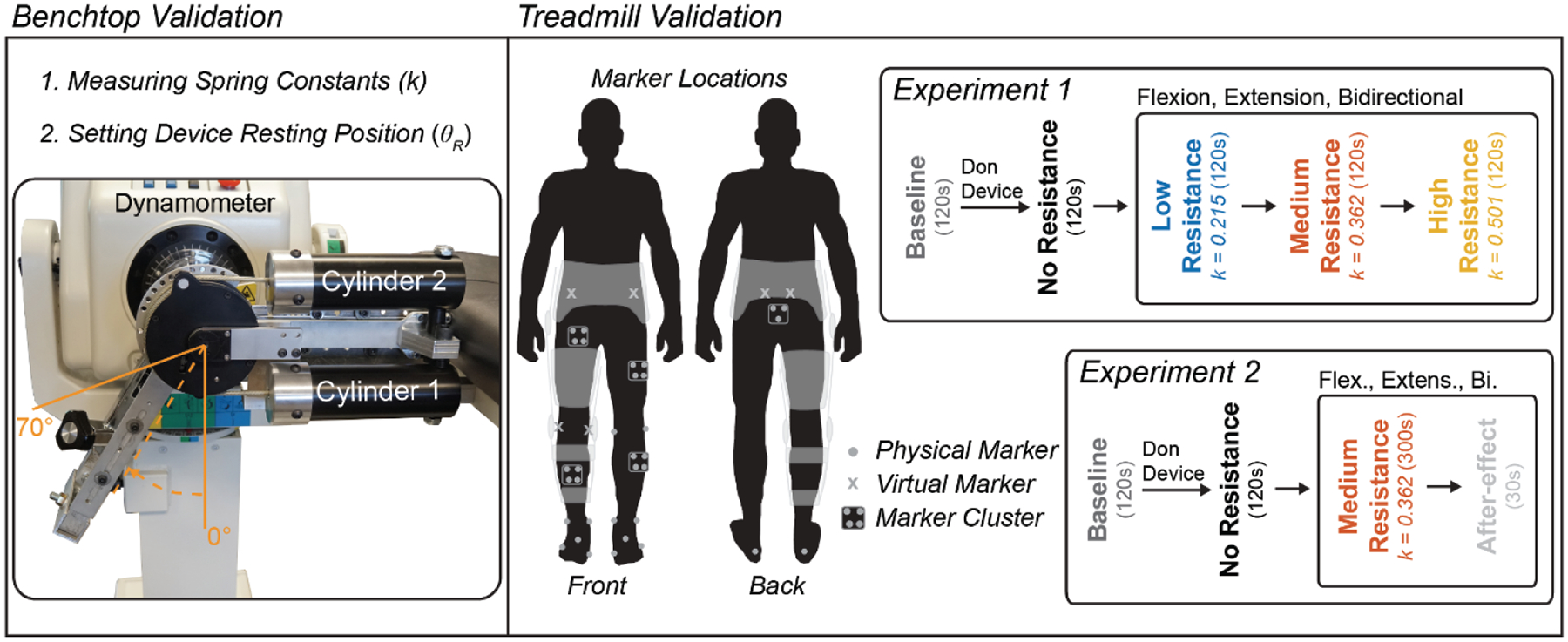
Schematic depicting benchtop and treadmill validation experiments. (Left) For benchtop testing the device was connected to a dynamometer to measure the stiffness of (i.e., calibrate) the springs and validate our ability to alter the resting position of the spring system. (Right) The device was worn over the knee to test its ability to convey forces to the leg during treadmill walking. Separate experiments were run to see (1) how the device performed under three different conditions (i.e., resisting knee flexion, extension, or bidirectionally) at multiple resistance levels and (2) how these conditions augment adaptation with the device, as we measured kinematics, kinetics, and muscle activation.
To calibrate the springs used in the device, individual springs were placed into the cylinder of the lower subassembly (Fig. 2 Left; Cylinder 1) and the clutch was engaged at 0 deg (i.e., θr1= 0). Meanwhile, the upper cylinder was left empty. The program on the dynamometer was executed twice to both measure the spring stiffness and to measure repeatability.
To validate our ability to alter the resting position of the device, springs were loaded into the top and bottom cylinders of the device (i.e., k1= k2= 0.215 N m deg−1). To set the resting position of the device at different angles, the clutches of the counteracting subassemblies were engaged at various positions (θr1 and θr2) in accordance with equations 2 and 6. The resting positions were set as follows: θr1= −50 and θr2= 70 for θR= 10; θr1= −30 and θr2= 70 for θR= 20; θr1= −10 and θr2= 70 for θR= 30; θr1= 0 and θr2= 70 for θR= 35; θr1= 0 and θr2= 80 for θR= 40; θr1= 0 and θr2= 100 for θR= 50; and θr1= 0 and θr2= 120 for θR= 60 deg. Once the spring mechanism was set, the arm was relocated to the zero position and the dynamometer program was run.
C. Evaluation of the Device during Treadmill Walking
To evaluate the ability of the device to provide resistance during walking, the elastic leg brace was worn by a healthy participant (male, aged: 24 years, height: 185 cm, mass: 93 kg, dominant leg: right) during two validation experiments. The first experiment evaluated the device during walking under various loading conditions—including having the device provide resistance to knee flexion, extension, or bidirectionally—at several resistance intensities, as we measured electromyography (EMG), kinematics, and kinetics. The second experiment was devised to see how the device could influence motor adaptation by measuring the kinematic aftereffects that occurred after sustained walking under these loading conditions. In preparation for these experiments, the participant reviewed and signed an informed consent document approved by the University of Michigan Institutional Review Board (HUM00093673, approved on 5/24/2018).
1). Experiment 1: Device Performance during Walking
The protocol for experiment 1 (Fig. 2 Right) was as follows: EMG sensors (Trigno Avanti, Delsys, Natick, MA, US) were placed over several lower extremity muscles used during walking (incl. the quadriceps [vastus medialis, VM; rectus femoris, RF], hamstrings [medial hamstring, MH; lateral hamstring, LH], tibialis anterior, medial gastrocnemius, soleus, and gluteus medius). Reflective markers were then placed for motion capture (Qualisys Track Manager [QTM], Qualisys, Göteborg, SE). Refer to the supplement (Section I) for additional details about the experimental setup, such as marker placements. We then measured the participant’s static posture (see supplemental section IIA for details) without the device. Next, the participant performed a Baseline trial, where he walked on an instrumented split-belt treadmill (Bertec, Columbus, OH, US) at 1 m s−1 for a duration of 120s (note, this was the speed throughout all experiments). We then assisted the participant in donning the device. Once the device was fitted properly, we performed a second static trial in case any marker clusters had shifted. The participant then walked on the treadmill while wearing the device with no resistance (i.e., with the clutches disengaged and without springs in the cylinders). From this trial, we measured the maximum knee flexion and extension angles (i.e., the range of motion limits: ROMmin = 0 degrees and ROMmax = 66 degrees) using the encoder on the device. These angles were used to provide real-time feedback that encouraged the participant to walk with their normal range of motion during resisted trials (see supplemental section III for details).
The participant then walked with the device providing resistance to their knee joint during three loading conditions (Resisting Flexion, Extension, and Bidirectional) at three intensities that used different spring stiffnesses (Low [ki= 0.215 N m deg−1, Medium [ki= 0.362 N m deg−1], and High [ki= 0.501 N m deg−1]). For each condition, the participant walked for 120 s with resistance, then was given 60 s of rest before progressing to the next intensity. To resist flexion, the spring was inserted into the first cylinder (k1) and the clutch for that cylinder was engaged while the participant’s leg was fully extended (θr1= ROMmin). To resist extension, the spring was inserted into the second cylinder (k2) and the clutch was engaged while the participant’s leg was flexed to the peak flexion angle (θr2= ROMmax). To resist bidirectionally, the springs were placed into both cylinders (k1 and k2) and the clutch on the first cylinder was engaged at ROMmin while the clutch for the second cylinder was engaged at ROMmax; hence, the resting position of the device was now located in the center of the range of motion (θR=(ROMmax–ROMmin)/2=33 deg) and the spring stiffness (keff) was doubled so that the peak device moments matched those of the flexion and extension conditions.
2). Experiment 2: Aftereffects Following Adaptation
Experiment 2 occurred on a separate day; however, the protocol (Fig. 2 Right) and experimental setup were very similar to the first experiment. Following the no resistance trial, we configured the device to resist knee flexion using a medium stiffness spring (ki= 0.362 N m deg−1). The participant then walked on the treadmill for 300 s with resistance and visual feedback. Once 300 s had elapsed, we stopped the treadmill then removed the resistance and feedback. The participant was then instructed to walk in a manner that felt natural, and they walked for an additional 30 s while we measured the aftereffect. The participant then received a break (120 s), after which he walked again for 300 s without resistance to wash-out any lingering effects from the previous condition. Following the washout, we repeated this procedure for the Extension and Bidirectional configurations.
D. Data Processing
1). Benchtop Validation of the Device
Throughout the benchtop validation experiments, torque and position data were recorded from the dynamometer at a frequency of 100 Hz. These data were then imported into MATLAB for processing (vR2019a, MathWorks, Natick, MA, US). For each spring, we performed a linear regression to find the slope relationship (i.e., spring stiffness k) between the output torque and the angle of the device. These measured values were then compared with those provided by the spring manufacturer. Additionally, we calculated Pearson’s correlation coefficient, and slope of the regression line, and coefficient of variation between the two sets of calibration data in order to measure repeatability (see supplemental section IV for details). For validating our ability to alter the resting position of the device, the torque data were plotted against the angle of the device. We then measured the angle at which the torque crossed zero and compared that with the predicted value determined using equation 2.
2). Evaluation of the Device During Treadmill Walking
a). Electromyography
The amplitude of surface EMG was used to determine how the device’s various loading configurations could alter muscle activation during walking. Raw EMG data were collected in Qualisys Track Manager (QTM) and sampled at 2000 Hz. Using a custom LabVIEW program, these raw data were band-pass filtered (20–500 Hz), rectified, and smoothed using a zero phase-lag low-pass Butterworth digital filter (8th order, 6 Hz). The resulting EMG profiles were then normalized using maximum voluntary contractions; hence units were expressed as a percentage of this activation (% MVC). We ensemble averaged the EMG data across strides to compute mean EMG profiles during each trial. Strides were determined to begin at heel-strike. Processed EMG data for all muscles can be downloaded at: http://neurro-lab.engin.umich.edu/downloads (Experiment 1 EMG Data).
b). Device Moments and Powers
The torque and power that the device generated was calculated using the calibrated spring constants and the encoder data from the device. During each trial involving the leg brace, we collected the device angle from the encoder at a rate of 62.5 Hz using a custom LabVIEW program. For processing, we upsampled the encoder data to 2000 Hz, so that it matched the force plate data. We then performed a numerical derivative on the angle data to calculate the angular velocity. We used equation 3 to estimate the output torque, then multiplied this torque by the angular velocity to estimate power. These data were segmented into strides and ensemble averaged to yield a profile representing the average torque and power for each trial.
c). Kinematics and Kinetics
Motion capture and force plate data were collected using QTM and sampled at 200 Hz and 2000 Hz, respectively. Gaps in the motion capture data were filled and markers were labeled in QTM. These data were then exported to Visual3D (C-Motion Inc., Germantown, MD, US) for further processing (see supplemental section IIC for full details). Briefly, skeletal models were constructed from the static trials (see supplemental section IIB for details) and applied to the dynamic walking trials. The marker position data and force plate data were low-pass filtered using a zero phase-lag Butterworth digital filter (6 Hz) to remove motion artifacts and high frequency noise due to the treadmill motors, respectively. From these filtered data, we then computed the sagittal plane kinematics and kinetics (internal moments and powers) of the hip, knee, and ankle joints of the right leg (the leg that was wearing the brace). These data were segmented at heel-strike and ensemble averaged across strides. We then subtracted the average device moment and power from the knee data to account for the device’s contribution. Processed kinematics and kinetics data (for all joints) can be downloaded at: http://neurro-lab.engin.umich.edu/downloads (Experiment 1 Biomechanics Data). Note that only kinematics from the aftereffect trials were compared for experiment 2.
III. Results
A. Benchtop Validation of the Device
Calibration curves for the individual springs can be found in Fig. 3 (Left). These data are compared with theoretical stiffnesses (based on the factory spring calibrations) in supplemental table 1. Overall, the results indicated that the stiffness parameters (ki) of the device could be accurately altered in evenly spaced increments (approximately 0.112 N m deg−1 change in stiffness between springs). On average, the absolute percentage error in spring stiffness measured from the device, when compared with our theoretical calculations, was 9.8%. Interestingly, our measured stiffnesses were higher than theoretical for the smaller springs, and lower than theoretical for the larger (stiffer) springs. These errors likely occurred due to hysteresis caused by friction in the system, or deformation of the system, respectively (Supplemental Fig. 3). Additionally, these characterization curves were repeatable over two cycles of loading (see supplemental section IV).
Fig. 3.
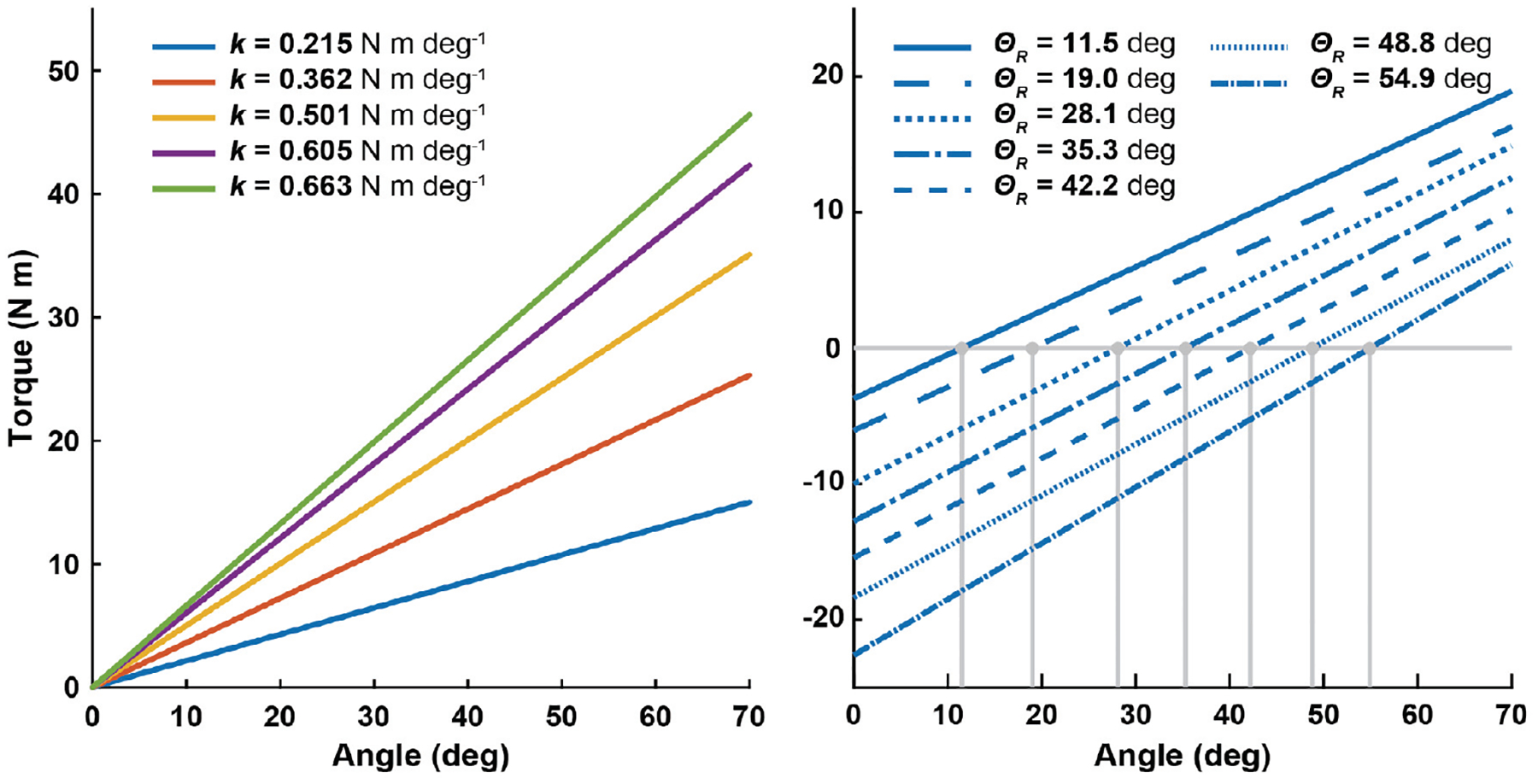
Results from benchtop testing. (Left) The stiffness of the calibrated springs (k) is indicated by the slope of a linear fit. (Right) The subassemblies were configured to alter the resting position (θR) of the device. The angle where the torque crossed zero using the lightest spring (k=0.215 N m deg−1) is indicated with a vertical line extending down to the x-axis. In both plots, the y-axis indicates torque and the x-axis indicates the angle as measured with the dynamometer
Additionally, we validated the ability to change the resting position of the device (θR). A linear fit of these data can be found in Fig. 3 (Right). We then compared our measured resting position with the theoretical resting position calculated based on equation 6 (Supplemental Table 2). On average, the absolute difference between our measured values and the theoretical values was 1.9 deg. This is much smaller than the minimum increment of the ratchet gear, 15 deg.
B. Experiment 1: Device Performance during Walking
1). Resisting Flexion
Walking with the device set to provide no resistance did not have a large effect on any of the metrics measured in this experiment when compared with baseline walking (Fig. 4). When resisting flexion, the device output max resistances of 14.1, 23.4, and 33.1 Nm for the low, medium, and high resistances, respectively. The peak resistance occurred during early swing, where knee flexion is typically the largest. Consequently, we found the knee flexion moment was increased during the swing phase. Surprisingly, the knee extension moment increased during the stance phase—a movement that should have been assisted during this condition. We believe this occurred because the knee was flexed at heel-strike; hence, knee extension had to counteract the bodyweight. Interestingly, we saw that the joint power was more negative (i.e., absorption increased) during early stance and late swing. Meanwhile, joint power was more positive (i.e., generation increased) during the early swing phase. Muscle activation of the hamstrings was increased during late stance and throughout the swing phase of gait. Quadriceps muscle activation was slightly increased during early stance.
Fig. 4.

Gait biomechanics and electromyography while walking with the device set to resist knee flexion. The device was configured to provide three levels (Low, Medium, and High) of resistance to the leg during flexion (i.e., the device was providing an extension torque). The diagram at the top left shows the sign convention for angles and moments. Positive knee powers indicate the joint was generating power (i.e., contracting concentrically) while negative powers indicate the joint was absorbing power (i.e., contracting eccentrically). Plots on the far right show the muscle activation of the quadriceps (vastus medialis [VM], rectus femoris [RF]) and hamstring muscles (medial hamstring [MH], and lateral hamstring [LH]). In all plots, the x-axis indicates the percentage of the gait cycle over a stride. Units: deg = degrees, Nm = newton meters, W = watts, %MVC = percentage of maximum voluntary contraction.
2). Resisting Extension
During this condition, the device output maximum resistances of 11.4, 19.0, and 22.5 Nm for the low, medium, and high resistances, respectively (Fig. 5). This peak occurred during the stance and late swing phases, where the knee is extended. Generally, the device increased the knee extension moment during the stance and the late swing phase. Joint power was more negative during the early stance phase (i.e., absorption increased). During late swing, a period of the gait cycle where the hamstrings usually act eccentrically, we saw less power absorption. Muscle activations of the quadriceps muscles were greatly increased during early–mid stance and late swing. The hamstrings showed some increased muscle activation during late stance.
Fig. 5.

Gait biomechanics and electromyography while walking with the device set to resist knee extension. The device was configured to provide three levels (Low, Medium, and High) of resistance to the leg during extension (i.e., the device was providing a flexion torque). The diagram at the top left shows the sign convention for angles and moments. Positive knee powers indicate the joint was generating power (i.e., contracting concentrically) while negative powers indicate the joint was absorbing power (i.e., contracting eccentrically). Plots on the far right show the muscle activation of the quadriceps (vastus medialis [VM], rectus femoris [RF]) and hamstring muscles (medial hamstring [MH], and lateral hamstring [LH]). In all plots, the x-axis indicates the percentage of the gait cycle over a stride. Units: deg = degrees, Nm = newton meters, W = watts, %MVC = percentage of maximum voluntary contraction.
3). Resisting Bidirectionally
During the bidirectional resistance condition, the device succeeded in providing both flexion and extension resistances (Fig. 6). During this condition, the device output maximum extension torques (i.e., resisting flexion) of 13.9, 23.7, and 31.9 Nm, and maximum flexion torques (i.e., resisting extension) of 10.8, 14.4, and 16.4 Nm for the low, medium, and high resistances, respectively. On average, the bidirectional resistance was 10% below what was seen during the unidirectional resistance conditions, and these discrepancies were more pronounced when resisting extension. All springs elicited increases in knee extension moment during the early stance phase and knee flexion moment during early–mid swing. The extra knee extension moment during the stance phase led to more negative power (i.e., absorption increased) after heel-strike, followed by an increase in positive power (i.e., increased generation) in early-mid stance. These were paralleled by increases in quadriceps muscle activation at these phases. At the beginning of the swing phase joint power was more positive (i.e., generation increased), which was paralleled by large increases in hamstring muscle activation.
Fig. 6.

Gait biomechanics and electromyography while walking with the device set to resist the knee bidirectionally (i.e., resisting both flexion and extension). The device was configured to provide three levels (Low, Medium, and High) of bidirectional resistance. The diagram at the top left shows the sign convention for angles and moments. Positive knee powers indicate the joint was generating power (i.e., contracting concentrically) while negative powers indicate the joint was absorbing power (i.e., contracting eccentrically). Plots on the far right show the muscle activation of the quadriceps (vastus medialis [VM], rectus femoris [RF]) and hamstring muscles (medial hamstring [MH], and lateral hamstring [LH]). In all plots, the x-axis indicates the percentage of the gait cycle over a stride. Units: deg = degrees, Nm = newton meters, W = watts, %MVC = percentage of maximum voluntary contraction.
C. Experiment 2: Aftereffects Following Adaptation
Removing the resistance and visual feedback resulted in kinematic aftereffects that varied based on the type of resistance provided (Fig. 7). After walking with resistance to knee flexion, hip and knee flexion angles increased and the ankle was more dorsiflexed throughout the swing phase when compared with the walking with no resistance. When viewed as an ankle trajectory, the participant was lifting their foot higher during the swing phase. Walking with resistance to knee extension resulted in increased knee extension and ankle plantarflexion during the stance phase of the aftereffect trial. The ankle trajectory aftereffect had a larger x-excursion, indicating a longer step length. Walking with bidirectional resistance appeared to combine the effects seen in the flexion and extension conditions. Hip flexion, knee flexion, and ankle dorsiflexion increased during the swing phase, while knee extension and ankle plantarflexion increased during the stance phase. This resulted in an ankle trajectory where the foot was lifted higher and step length was larger. Notably, knee kinematics returned to the levels seen during the no resistance trial following the washout trials (Supplemental Fig. 4).
Fig. 7.

Kinematic aftereffects following the removal of resistance. Comparing the kinematics before and after a training allowed us to measure the aftereffects for each resistance configuration. The top three rows depict the sagittal hip, knee, and ankle joint angles. The y-axis indicates the angle in degrees, while the x-axis indicates the percentage of the gait cycle over a stride. The bottom row depicts the sagittal ankle trajectories (i.e., the path that the ankle traveled) relative to the hip and offset from ground. In these plots, the y-axis indicates movement in the vertical direction (in meters), while the x-axis indicates movement in the anterior-posterior direction. Hence, an increase in y means the foot was being lifted higher, while an increase in x-excursion could indicate a larger step length.
IV. Discussion
The goal of this research was to develop a unique exoskeleton device that could provide various types of elastic resistance during walking. Subsequently, we created a novel elastic mechanism then fit the resulting device to a hip and knee orthosis, so as to provide resistance to the knee. During benchtop validation, we found the elastic mechanism could provide a nearly linear torque profile, and the device could be configured to alter the resting position of the spring system with high accuracy; thus, permitting resistance to flexion, extension, or both (i.e., bidirectionally). When validating during treadmill walking, we found that these resistance configurations could be used to target preferentially knee flexion, extension, or both. Moreover, the device could be used to increase power absorption at the joint, which could be used to eccentrically load the leg muscles. Lastly, once the resistance was removed, the different resistance configurations elicited different kinematic aftereffects. Thus, elastic devices such as this could serve as a diverse tool for functional resistance training paradigms aimed at targeting specific weaknesses or kinematic outcomes.
Through the treadmill walking validation experiment, we found that the resistance configurations could be used to target resistance to their respective joint motions. Specifically, while resisting knee flexion, the device increased knee flexion moment and hamstring activation during the swing phase; while resisting knee extension, the device increased knee extension moments and quadriceps activation during the early stance and late swing phases; and under a bidirectional resistance, the device increased both flexion and extension moments and activated each muscle group at their respective times. These were exciting findings, as most elastic devices are not capable of providing this level of targeted resistance; instead, they are limited to resisting a single joint motion [28–31, 33]. Additionally, we found this device could return energy to the user, which could be used to elicit eccentric contractions. This was clearly demonstrated during the late swing phase when the device was resisting knee flexion, as we found increased power absorption at the knee paired with increased hamstring activation. Hence, the hamstrings could have been acting eccentrically at that time.
The second walking validation experiment measured the aftereffects produced after training with the device. Aftereffects are believed to contain information about how the nervous system is adapting [37–39] and may serve as a marker for potential therapeutic gains, as aftereffects have been seen to transfer to overground walking [40, 41]. In our experiment, we measured the kinematic aftereffects (i.e., changes in hip and knee angles, and ankle trajectory) elicited by the three different resistance configurations as the user received visual feedback. We found that resisting flexion increased hip and knee flexion, which resulted in a higher step height; resisting extension increased knee extension, which resulted in an increased step length; and resisting bidirectionally combined these effects to produce a higher step with longer length. Hence, the different device configurations could be used to elicit different control strategies for walking, and perhaps, the device configuration could be selected to treat patient-specific gait deficits. However, we would like to note that the aftereffects we observed are likely a result of the combined resistance and visual feedback. Further, research on a larger group of patients would be needed to elucidate the added effects of visual feedback and to demonstrate the cumulative effects of repeated training with the device.
While the device mostly performed as intended, we also saw that performance reduced when storing large amounts of energy. During use, the device stored up to 28.35 J of energy (equivalent to lifting a 100 kg mass 3 cm). Under such high-energy conditions, we saw (1) errors between the theoretical and measured stiffnesses of springs during benchtop testing, and (2) diminished device moments with stiff springs during treadmill walking. Concerning (1), some errors arose in the form of hysteresis during loading/unloading due to friction between the plunger and cylinder (Supplemental Fig. 3). While only a small amount of friction was present at low loads, the problem was worse at high loads. This did not affect the functionality of the device, but friction could influence how the device feels to the user. Another source of error that could have contributed to (1) is the deformation of structural components within the device under large loads, which led to nonlinearity in the stiffness profile (and an underestimation of stiffness, Supplemental Fig. 3). Regarding (2), deformation of the leg brace components (i.e., the custom orthoses) hindered the devices ability to convey forces to the leg during walking. This was especially prominent when the device was resisting extension (Fig. 5). While walking, the large amount of energy stored by the device caused soft tissues and padding on the brace to compress, which caused the brace joint to shift relative to the participant’s leg. When this happened, the device was unable to output a torque that scaled relative to the spring stiffness. Hence, when resisting extension, although the spring stiffness scaled by 38% between the medium and high stiffness conditions, the peak device moment only scaled by 18%. However, many of these problems can be addressed with future iterations of the device.
While the current prototype provides a good starting point for this device, there are many alterations that could be incorporated into future iterations to improve general usability and expand the capabilities of the device. To improve usability, future iterations could minimize friction in the device, either by using a more rigid material for the cylinder or changing the type of spring so a cylinder is not needed (e.g., extension springs). However, we note that there are many benefits of compression springs (e.g., large force/deflection capability, small footprint, safety) that could outweigh the drawbacks of other types of springs (e.g., fragile, difficult to interface with, etc.). Additionally, the leg braces we used were never intended to convey external forces to the leg. Rather, they are typically used to limit range of motion after surgical procedures. Hence, forces could be better conveyed to the leg if the brace were designed to fit more snugly and contact bony places on the leg. Finally, there are a few alterations that could expand the capabilities of the device. First, the resistance of the device could be put under computer control. Typically, it is difficult to control elastic systems, as control is achieved by exchanging the spring or adding pre-tension, which requires a lot of power. This is a drawback to elastic devices and a reason why viscous devices are intriguing, as they offer more potential to be continuously controlled [8, 42]. However with this elastic brace, computer control could be achieved by controlling the clutches similar to an elastic device that has been used to reduce knee loading [34]. This modification would allow the device to remain passive (as power would not be introduced to the user) and would greatly increase the likelihood of the device being worn during everyday life. Lastly, the current device can be adapted to provide resistance to other joints and during other functional tasks. Although providing resistance to walking was the goal of this paper, the potential for such a device is far-reaching.
V. Conclusion
In this study, we developed a unique exoskeleton device to provide elastic resistances to the knee during walking. The elastic mechanism we designed allowed us to alter the stiffness of the device and control the resting position of the spring system. Thus, the device could be configured to provide resistance to joint flexion, extension, or bidirectionally. During walking, these configurations were shown to target specific joint motions and muscle groups. Additionally, the device was able to increase power absorption at the joint, which is atypical for many resistive leg braces. Lastly, the different resistance configurations elicited different kinematic aftereffects. Hence, such elastic devices could serve as a diverse tool for functional resistance training paradigms.
Supplementary Material
VI. Acknowledgment
The authors would like to thank Justin Lee for helping with designs, Jeffrey Wensman and the Orthotics and Prosthetics Center for procuring custom leg bracing, and Jim Tice and the LSA Scientific Instrument Shop.
This work was supported in part by the National Institutes of Health (Grant R21 HD092614), the National Science Foundation (Grant DGE 1256260), and the UM-BICI Collaboratory Initiative. Any opinions, findings, and conclusions or recommendations expressed in this material are those of the authors and do not necessarily reflect the views of the funding sources.
VII. References
- [1].Chen G, et al. , “Gait differences between individuals with post-stroke hemiparesis and non-disabled controls at matched speeds,” Gait Posture, vol. 22, pp. 51–6, August 2005. [DOI] [PubMed] [Google Scholar]
- [2].Kuo HK, et al. , “Cognitive function, habitual gait speed, and late-life disability in the national health and nutrition examination survey (nhanes) 1999–2002,” Gerontology, vol. 53, pp. 102–10, 2007. [DOI] [PMC free article] [PubMed] [Google Scholar]
- [3].Pietrosimone B, et al. , “Walking gait asymmetries 6 months following anterior cruciate ligament reconstruction predict 12-month patient-reported outcomes,” J. Orthop. Res, vol. 36, pp. 2932–2940, November 2018. [DOI] [PubMed] [Google Scholar]
- [4].Waite LM, et al. , “Motor function and disability in the dementias,” Int. J. Geriatr. Psychiatry, vol. 15, pp. 897–903, October 2000. [DOI] [PubMed] [Google Scholar]
- [5].Mozaffarian D, et al. , “Heart disease and stroke statistics––2015 update: A report from the american heart association,” Circulation, vol. 131, pp. e29–322, January 27 2015. [DOI] [PubMed] [Google Scholar]
- [6].Perry J, et al. , “Classification of walking handicap in the stroke population,” Stroke, vol. 26, pp. 982–9, June 1995. [DOI] [PubMed] [Google Scholar]
- [7].Brandes M, et al. , “Quantity versus quality of gait and quality of life in patients with osteoarthritis,” Gait Posture, vol. 28, pp. 74–9, July 2008. [DOI] [PubMed] [Google Scholar]
- [8].Washabaugh EP, et al. , “A novel application of eddy current braking for functional strength training during gait,” Ann. Biomed. Eng, vol. 44, pp. 2760–73, September 2016. [DOI] [PMC free article] [PubMed] [Google Scholar]
- [9].Cooke EV, et al. , “Efficacy of functional strength training on restoration of lower-limb motor function early after stroke: Phase i randomized controlled trial,” Neurorehabil. Neural Repair, vol. 24, pp. 88–96, January 2010. [DOI] [PubMed] [Google Scholar]
- [10].Donaldson C, et al. , “Effects of conventional physical therapy and functional strength training on upper limb motor recovery after stroke: A randomized phase ii study,” Neurorehabil. Neural Repair, vol. 23, pp. 389–97, May 2009. [DOI] [PubMed] [Google Scholar]
- [11].Blackburn JT, et al. , “Quadriceps function and gait kinetics after anterior cruciate ligament reconstruction,” Med. Sci. Sports Exerc, vol. 48, pp. 1664–70, September 2016. [DOI] [PubMed] [Google Scholar]
- [12].Hsu AL, et al. , “Analysis of impairments influencing gait velocity and asymmetry of hemiplegic patients after mild to moderate stroke,” Arch. Phys. Med. Rehabil, vol. 84, pp. 1185–93, August 2003. [DOI] [PubMed] [Google Scholar]
- [13].Kautz SA and Brown DA, “Relationships between timing of muscle excitation and impaired motor performance during cyclical lower extremity movement in post-stroke hemiplegia,” Brain, vol. 121 (Pt 3), pp. 515–26, March 1998. [DOI] [PubMed] [Google Scholar]
- [14].Simao CR, et al. , “Immediate effects of a single treadmill session with additional ankle loading on gait in children with hemiparetic cerebral palsy,” NeuroRehabilitation, vol. 44, pp. 9–17, 2019. [DOI] [PubMed] [Google Scholar]
- [15].Duclos C, et al. , “Effects of walking with loads above the ankle on gait parameters of persons with hemiparesis after stroke,” Clin. Biomech. (Bristol, Avon), vol. 29, pp. 265–71, March 2014. [DOI] [PubMed] [Google Scholar]
- [16].Lam T, et al. , “Treadmill-based locomotor training with leg weights to enhance functional ambulation in people with chronic stroke: A pilot study,” J. Neurol. Phys. Ther, vol. 33, pp. 129–35, September 2009. [DOI] [PubMed] [Google Scholar]
- [17].Browning RC, et al. , “The effects of adding mass to the legs on the energetics and biomechanics of walking,” Med. Sci. Sports Exerc, vol. 39, pp. 515–25, March 2007. [DOI] [PubMed] [Google Scholar]
- [18].Washabaugh EP, et al. , “Functional resistance training during walking: Mode of application differentially affects gait biomechanics and muscle activation patterns,” Gait Posture, vol. 75, pp. 129–136, January 2020. [DOI] [PMC free article] [PubMed] [Google Scholar]
- [19].Bohannon RW, “Measuring knee extensor muscle strength,” Am. J. Phys. Med. Rehabil, vol. 80, pp. 13–8, January 2001. [DOI] [PubMed] [Google Scholar]
- [20].Conner BC, et al. , “Adaptive ankle resistance from a wearable robotic device to improve muscle recruitment in cerebral palsy,” Ann. Biomed. Eng, vol. 48, pp. 1309–1321, April 2020. [DOI] [PMC free article] [PubMed] [Google Scholar]
- [21].Lam T, et al. , “Contribution of feedback and feedforward strategies to locomotor adaptations,” J. Neurophysiol, vol. 95, pp. 766–73, February 2006. [DOI] [PubMed] [Google Scholar]
- [22].Noel M, et al. , “An electrohydraulic actuated ankle foot orthosis to generate force fields and to test proprioceptive reflexes during human walking,” IEEE Trans. Neural. Syst. Rehabil. Eng, vol. 16, pp. 390–9, August 2008. [DOI] [PubMed] [Google Scholar]
- [23].Washabaugh EP and Krishnan C, “A wearable resistive robot facilitates locomotor adaptations during gait,” Restor. Neurol. Neurosci, vol. 36, pp. 215–223, 2018. [DOI] [PMC free article] [PubMed] [Google Scholar]
- [24].Blanchette AK, et al. , “Modifications in ankle dorsiflexor activation by applying a torque perturbation during walking in persons post-stroke: A case series,” J. Neuroeng. Rehabil, vol. 11, p. 98, June 9 2014. [DOI] [PMC free article] [PubMed] [Google Scholar]
- [25].Martini E, et al. , “Gait training using a robotic hip exoskeleton improves metabolic gait efficiency in the elderly,” Sci. Rep, vol. 9, p. 7157, May 9 2019. [DOI] [PMC free article] [PubMed] [Google Scholar]
- [26].Stoeckmann TM, et al. , “Elastic, viscous, and mass load effects on poststroke muscle recruitment and co-contraction during reaching: A pilot study,” Phys. Ther, vol. 89, pp. 665–78, July 2009. [DOI] [PMC free article] [PubMed] [Google Scholar]
- [27].Kleim JA and Jones TA, “Principles of experience-dependent neural plasticity: Implications for rehabilitation after brain damage,” J Speech Lang Hear Res, vol. 51, pp. S225–39, February 2008. [DOI] [PubMed] [Google Scholar]
- [28].Cherry MS, et al. , “Running with an elastic lower limb exoskeleton,” J. Appl. Biomech, vol. 32, pp. 269–77, June 2016. [DOI] [PubMed] [Google Scholar]
- [29].Cherry MS, et al. , “Design and fabrication of an elastic knee orthosis: Preliminary results,” in ASME 2006 International Design Engineering Technical Conferences and Computers and Information in Engineering Conference, 2006, pp. 565–573. [Google Scholar]
- [30].Mankala KK, et al. , “Novel swing-assist un-motorized exoskeletons for gait training,” J. Neuroeng. Rehabil, vol. 6, p. 24, July 3 2009. [DOI] [PMC free article] [PubMed] [Google Scholar]
- [31].Sulzer JS, et al. , “A highly backdrivable, lightweight knee actuator for investigating gait in stroke,” IEEE Trans. Robot, vol. 25, pp. 539–548, June 2009. [DOI] [PMC free article] [PubMed] [Google Scholar]
- [32].Collins SH, et al. , “Reducing the energy cost of human walking using an unpowered exoskeleton,” Nature, vol. 522, pp. 212–5, June 11 2015. [DOI] [PMC free article] [PubMed] [Google Scholar]
- [33].Shamaei K, et al. , “Design and evaluation of a quasi-passive knee exoskeleton for investigation of motor adaptation in lower extremity joints,” IEEE Trans. Biomed. Eng, vol. 61, pp. 1809–21, June 2014. [DOI] [PubMed] [Google Scholar]
- [34].Shamaei K, et al. , “Biomechanical effects of stiffness in parallel with the knee joint during walking,” IEEE Trans. Biomed. Eng, vol. 62, pp. 2389–401, October 2015. [DOI] [PubMed] [Google Scholar]
- [35].Krishnan C and Theuerkauf P, “Effect of knee angle on quadriceps strength and activation after anterior cruciate ligament reconstruction,” J. Appl. Physiol. (1985), vol. 119, pp. 223–31, August 1 2015. [DOI] [PMC free article] [PubMed] [Google Scholar]
- [36].Pak S and Patten C, “Strengthening to promote functional recovery poststroke: An evidence-based review,” Top Stroke Rehabil, vol. 15, pp. 177–99, May-Jun 2008. [DOI] [PubMed] [Google Scholar]
- [37].Morton SM and Bastian AJ, “Cerebellar contributions to locomotor adaptations during splitbelt treadmill walking,” J. Neurosci, vol. 26, pp. 9107–16, September 6 2006. [DOI] [PMC free article] [PubMed] [Google Scholar]
- [38].Shadmehr R and Mussa-Ivaldi FA, “Adaptive representation of dynamics during learning of a motor task,” J. Neurosci, vol. 14, pp. 3208–24, May 1994. [DOI] [PMC free article] [PubMed] [Google Scholar]
- [39].Gordon KE, et al. , “Locomotor adaptation to a soleus emg-controlled antagonistic exoskeleton,” J. Neurophysiol, vol. 109, pp. 1804–14, April 2013. [DOI] [PMC free article] [PubMed] [Google Scholar]
- [40].Reisman DS, et al. , “Split-belt treadmill adaptation transfers to overground walking in persons poststroke,” Neurorehabil. Neural Repair, vol. 23, pp. 735–44, September 2009. [DOI] [PMC free article] [PubMed] [Google Scholar]
- [41].Regnaux JP, et al. , “Effects of loading the unaffected limb for one session of locomotor training on laboratory measures of gait in stroke,” Clin. Biomech. (Bristol, Avon), vol. 23, pp. 762–8, July 2008. [DOI] [PubMed] [Google Scholar]
- [42].Washabaugh E, et al. , “A portable passive rehabilitation robot for upper-extremity functional resistance training,” IEEE Trans. Biomed. Eng, vol. 66, pp. 496–508, February 2019. [DOI] [PMC free article] [PubMed] [Google Scholar]
Associated Data
This section collects any data citations, data availability statements, or supplementary materials included in this article.