Abstract
The rapid oscillation of galvanometric resonant optical scanners introduces linear astigmatism that degrades transverse resolution, and in confocal systems, also reduces signal [V. Akondi et al., Optica 7, 1506, 2020]. Here, we demonstrate correction of this aberration by tilting reflective or refractive optical elements for a single vergence or a vergence range, with and without the use of an adaptive wavefront corrector such as a deformable mirror. The approach, based on nodal aberration theory, can generate any desired third order aberration that results from tilting or decentering optical surfaces.
1. Introduction
Resonant galvanometric scanners are used in a diverse range of applications, including microscopy [1–3], retinal imaging [4–6], and optical coherence tomography [7–9]. Their rapid sinusoidal oscillation, which enables high speed imaging and sensing, induces dynamic oblique astigmatism that is proportional to the angular displacement. This astigmatism can result in up to a factor of two transverse resolution degradation, and up to an order of magnitude signal reduction in confocal instruments [10]. Here, we propose the compensation of this aberration, linear with angular displacement, by tilting optical elements following the resonant scanner. Our approach is based on the nodal aberration theory (NAT) prediction that the tilting and/or decentering of optical elements introduces linear astigmatism. NAT, developed by Shack and Thompson [11], describes the aberrations of optical systems with tilted and/or decentered surfaces. Recently, this theory has been extended to include non-rotationally symmetric surfaces, such as, the primary mirror of Ritchey-Chrétien telescopes [12], φ-polynomial surfaces [13], and Zernike polynomial surfaces [13,14]. Despite its mathematical elegance and physical insight, there are very few practical demonstrations of NAT [14–18], such as the one provided here.
In the next section we introduce NAT concepts, notation, and conventions. Then, we propose the minimization of the analytical field-averaged variance of third order aberrations, as a method for finding the surface tilts and decenters that achieve a desired target wavefront. We then calculate this field-averaged wavefront variance for circular pupil and a 1-dimensional (line segment) field of view to describe the resonant scanner. To deal with the need for correction of aberrations for multiple conjugate planes simultaneously, we calculate the vergence-averaged field-averaged wavefront variance. Both these quantities, calculated analytically here, are the continuous equivalent of the discrete merit functions used by ray tracing software to design and optimize optical instruments, thus providing a natural conceptual understanding for optical designers. The third section of the manuscript provides a description of two afocal relays used here to illustrate the correction of linear astigmatism caused by a resonant scanner. This is followed by the analytical calculation of the NAT aberration coefficients due to the tilting and decentering of the optical elements in the relays. The fourth section consists of a description of the parameters used for the calculation of the tilt solutions and the numerical optimization using ray tracing software. The results section shows the comparison of the calculated solutions against those found by ray tracing software, in terms of the estimated tilts, wavefront maps and wavefront root mean squared. Finally, a summary of the method, findings and observation is provided.
2. Nodal aberration theory
The scalar wavefront aberrations of rotationally symmetric optical systems can be described as the weighted sum of the contributions from individual surfaces, each of which is represented by a polynomial of normalized field and pupil coordinates [19]. NAT extends this mathematical description to include rotationally symmetric systems perturbed through the tilting and/or decentering of optical elements [11,13,20,21]. In NAT, the normalized pupil and field positions are represented as the vectors and , respectively (see Fig. 1), and the wavefront aberrations are calculated as the weighted sum of the aberration field for each surface j shifted by a vector [11],
| (1) |
Fig. 1.
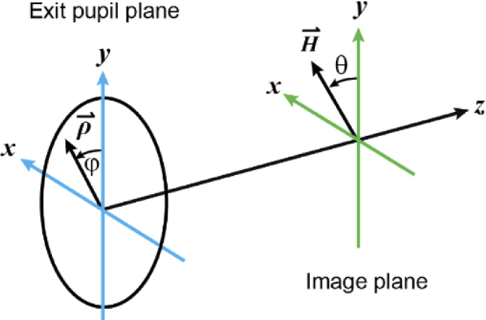
Normalized pupil position vector and field position vector , which in Cartesian coordinates are and , respectively.
Here , , and the field shift vector is defined as [21],
| (2) |
where is the chief ray angle of incidence in the centered system, and is the optical axis ray (OAR) angle of incidence measured with respect to the local axis of the tilted and/or decentered surface. The OAR is a real (as opposed to paraxial) ray that connects the center of the object and the center of the aperture stop [11]. The field positions at which each term in Eq. (1) becomes zero are the aberration nodes which give the mathematical formalism its name.
The vectors in Eq. (1) are Cartesian coordinate vectors, with their dot and cross products defined in the conventional way, and their multiplication defined as where and [11]. If the two vectors were complex numbers, this new operation would be their multiplication, with the output being a coplanar vector with magnitude and an angle .
In order to calculate the field displacement vector , we first need to calculate the OAR angle of incidence, which is defined as [21],
| (3) |
with denoting the unit vector normal to the object plane and its conjugates, the unit direction vector of the optical axis ray, and the unit surface normal vector at the intersection point with the OAR, as shown in Fig. 2 [21].
Fig. 2.
Unit vectors used to calculate the optical axis ray angle of incidence in an optical system with tilted optical elements for a reflective surface (left) and a refractive surface (right).
2.1. Tilt convention and OAR angle of incidence
In what follows, we adopt the tilt convention used by the ray tracing software OpticStudio (Zemax, Kirkland, WA, USA), which is depicted in Fig. 3. In this way,
| (4) |
Fig. 3.
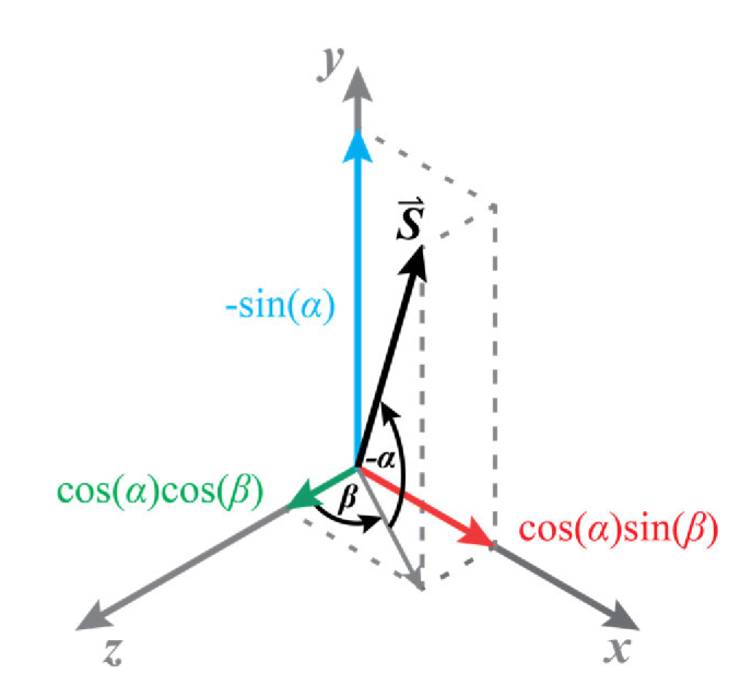
Tilt definition used to derive the unit surface normal vector , the optical axis ray angle of incidence , the field shift vector , and eventually, the wavefront aberrations.
Now, for each surface j, is normal to the object plane in an unperturbed rotationally symmetric optical system, and thus, has Cartesian coordinates [21]. If the optical elements are titled but not decentered, as it is the case in the optical systems considered in this work, the OAR unit vector will be coaxial with , which when substituted in Eq. (3) yields,
| (5) |
Here it is important to note that when a ray reflects off a mirror, the angle in Eq. (5) must be multiplied by the refractive index of the medium before the surface. If the medium is air and the surfaces are all reflective, then the refractive index should be considered as .
2.2. Third order aberrations
For many optical systems, the terms in Eq. (1) referred to as third-order aberrations (), provide an adequate description of the optical performance. These third-order wavefront aberrations in a perturbed system are written as [11],
| (6) |
with
| (7) |
where we have excluded distortion () because it does not affect image sharpness. It should be emphasized here, that the wavefront coefficients are calculated as functions of paraxial ray tracing quantities [22] in the rotationally symmetric system, and remain unchanged when surfaces are tilted and/or decentered.
The last term in Eq. (6) is the third order astigmatism, where the scalar is the amplitude of the astigmatism quadratic in the radial field coordinate, and the vectors and , are the amplitudes of astigmatism that are linear and constant across the field of view, respectively. Equation (7) shows that these amplitude vectors depend on the quadratic astigmatism () and the field shift vector associated with each optical surface, which indicates that surfaces could be intentionally tilted to achieve a desired linear and constant astigmatism, which is the strategy we propose to compensate for the linear astigmatism introduce by the resonant scanner.
2.3. Wavefront targeting
Let us now consider the general problem of generating a target, or desired, wavefront in an initially rotationally symmetric system by tilting and/or decentering surfaces. That is, the optical elements and the distance between them have been selected and the only remaining parameters to adjust are their tilts and/or decenters. This can be pursued by first deriving the explicit formula for the residual field-averaged wavefront variance [23],
| (8) |
where, the integration is performed over the desired field of view and,
| (9) |
with the integration performed over the entire pupil. The surface tilts , and decenters , , can be chosen to minimize the field-averaged wavefront variance of the difference between the system and desired wavefronts by solving the system of equations,
| (10) |
for all surfaces j. From within the solutions to this system of equations, only the actual minima, as opposed to maxima or saddle points, are desirable solutions, which can be determined by calculating the sign of the local second derivatives. Finally, the tilts and decenters that correspond to local minima can be substituted in Eq. (8) to determine which of these is the global field-averaged wavefront variance minimum, thus providing the best fit to the desired wavefront. It should be noted, that even if the number of tilts and decenters was equal or greater than the number of equations, there is no guarantee that solutions for this set of transcendental equations exist.
2.4. Linear astigmatism targeting over a linear field of view
In this work, we aim to generate oblique linear astigmatism equal and opposite to that introduced by the dynamic distortion of a resonant scanner at the entrance pupil [10], which is described by the aberration coefficient . Our goal is to find the optical element tilts that achieve this desired linear astigmatism while keeping all other third order aberrations to a minimum. To achieve this, we first calculate the field-averaged wavefront variance over a circular pupil and the field of view of the resonant scanner, which is the line segment defined as and . If the field-constant defocus is chosen such that , that is, if the system is refocused to compensate for any defocus introduced by the surface tilting, we get,
| (11) |
Since tilting and decentering do not change the rotationally symmetric wavefront aberration coefficients, they can be ignored in the minimization process, as they are constant. The remaining terms can be thought of as the non-rotationally symmetric (NRS) wavefront variance,
| (12) |
The next step is to substitute here the formulae for each coefficient in terms of the optical system parameters, followed by the calculation of the partial derivatives with respect to the tilts , , , and , which will be equated to zero. Solving the resulting set of equations provides an initial set of angles that can be fed to ray tracing software for further refinement.
The search for analytical solutions for such system of equations could be pursued using symbolic calculation engines, such as MATLAB (Mathworks, Natick, MA, USA) or Mathematica (Wolfram Research, Champaign, IL, USA). Alternatively, numerical solutions could be pursued, although widely used solvers (e.g., MATLAB’s vpasolve or the Nelder–Mead minimization method implemented in MATLAB through the fminsearch function) might not be able to find the global field-averaged wavefront variance minimum, as they might get stuck in local minima.
Part of the challenge in solving such system of equations comes from the appearance of trigonometric functions of the tilts. Therefore, in what follows we sought approximate solutions by using the small angle approximation (i.e., ) on the formulae describing the wavefront aberration coefficients.
2.5. Linear astigmatism targeting across a vergence range
Some applications require a target wavefront across a range of conjugates, which for convenience we express in terms of vergence (), defined as the marginal ray angle divided by the ray height at the pupil. In this scenario, the quantity that should be minimized, assuming that all vergences within the range are of equal importance, is the field-averaged wavefront variance averaged across the desired vergence range,
| (13) |
where the first overbar denotes average across the field of view and the second across the vergence range.
3. Afocal relay
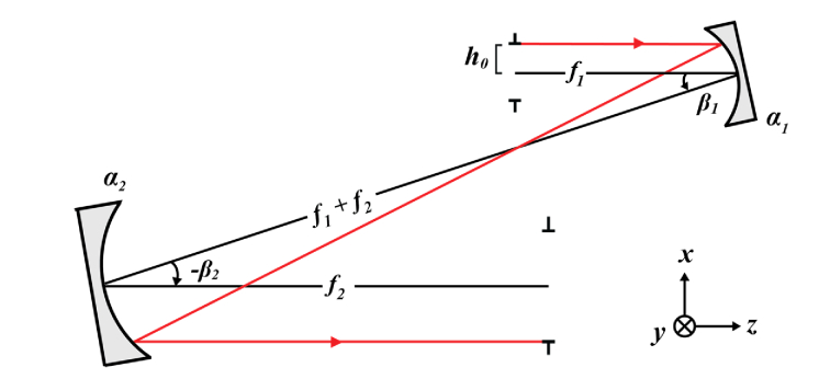
Let us now study an afocal relay consisting of two elements with focal lengths and , separated by the sum of their focal lengths, with the entrance pupil a focal length in front of the first optical element and the exit pupil, a focal length behind the second element. For the infinite conjugate in this system, the magnification is , with the marginal ray of height with radius at the entrance pupil emerging collimated.
3.1. Reflective afocal relay
When the proposed afocal relay is reflective and formed by two concave spherical mirrors as depicted in Fig. 4 below, the field shift vectors calculated using Eqs. (2) to (5) are,
| (14) |
Fig. 4.
Schematic of a reflective afocal relay with tilted elements, in which the black line represents the optical axis ray (OAR), the red line the marginal ray, and entrance pupil radius.
These can be combined with the traditional definition of the coefficients for rotationally symmetric aberrations of each surface [22] and substituted in Eq. (7) to calculate the non-rotationally symmetric wavefront aberration coefficients, which we show in Table 1 below as a function of vergence.
Table 1. Third order non-rotationally symmetric aberration coefficients for an afocal reflective relay formed by tilted concave spherical mirror for conjugates defined in terms of: vergence (), half field of view (), entrance pupil radius (), focal length of the first spherical mirror (), magnification ( and spherical mirror tilt about the local x- () and y-axis (). Note that is a scalar.
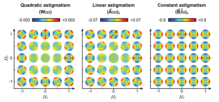
The difference between quadratic, linear and constant astigmatism is illustrated by the wavefront maps shown in Fig. 5 for zero vergence, with the spherical mirrors tilted to generate 0.07 waves of oblique astigmatism at the field edge. The quadratic astigmatism, unchanged by the tilting of the spherical mirrors rotate with the angle of the position vector . The linear astigmatism wavefronts, induced by the tilting of the spherical mirrors, rotate only by half of the position vector (see dashed lines), while the constant astigmatism wavefronts, also induced by the tilting, do not change their orientations across the field of view.
Fig. 5.
Quadratic, linear, and constant astigmatism wavefront plots for a reflective afocal relay formed by two concave spherical mirrors with = 400 mm, =800 mm, zero vergence and tilt angles , and .
3.2. Refractive afocal relay
For an equivalent afocal relay formed by two thin plano-convex lenses with refractive indices and , the non-rotationally symmetric aberration coefficients are calculated using the thin lens approximation, and therefore, each lens has only one field shift vector . The formulae were derived with the flatter surfaces facing the infinite conjugate, as depicted in Fig. 6, to minimize pupil aberrations. The results of the field shift vectors are similar to that of the reflective system, other than for replacing the factor due to the reflection on the mirror surfaces with the due to the refraction on the lens curved surfaces,
| (15) |
Fig. 6.
Systematic of the refractive afocal relay. Lenses are drawn with thicknesses for illustration purpose only. Black line represents the optical axis of the system, red line represents the marginal ray, and is the entrance pupil radius.
For simplicity, the coefficients in Table 2 have been calculated only for zero vergence.
Table 2. Third order non-rotationally symmetric aberration coefficients for infinite conjugates in an afocal refractive relay formed by two tilted thin plano-convex lenses in terms of: half field of view (), entrance pupil radius (), focal length of the first lens (), magnification ( and lens tilt about the local x- () and y-axis (). Note that is a scalar.
4. Simulation
The optical systems described above, together with a scanning mirror with dynamic distortion, were evaluated using the ray tracing software OpticStudio, assuming 680 nm light. Three afocal relays were studied: one formed by two concave spherical mirrors, one formed by two commercially available plano-convex singlets (LA1725-A, Thorlabs and PLCX-50.8-412.1-C, CVI Laser Optics, Albuquerque, NM, USA), and one formed by two achromatic doublets (ACT508-400-A, Thorlabs, Newton, NJ, USA, and DLB-50-800PM, Laser 2000, Huntingdon PE29 6XS, UK), all of them with 400 and 800 mm.
The dynamic distortion of the resonant scanner was simulated by inserting a Zernike fringe phase plate at the entrance pupil plane, with the amplitude of the 6th Zernike term varying linearly across the ±1° mechanical scanning angle, creating 0.07 or 0.28 waves of oblique astigmatism at the field edge [10]. Five uniformly spaced field points were simulated as five different OpticStudio configurations.
A continuous surface wavefront corrector, such as a deformable mirror, was modeled at the exit pupil plane as a second Zernike fringe phase plate that did not vary across the field of view, in which all coefficients up to the 8th order were allowed to change during the optimization process. To avoid introducing unwanted piston and tilts on the deformable mirror, the following constraints were imposed.
| (16) |
where is the coefficient of the Zernike polynomials . These constraints lead to and , which were set up in OpticStudio as pickups across all configurations, to account for the fact that the DM affects all configurations equally.
Two ray tracing optimization approaches were pursued for the zero vergence case, one without the DM and one with it, both using OpticStudio’s default merit function using centroid as reference (to ignore tilt). This merit function is a discretized version of the field-averaged wavefront variance. As mentioned earlier, field-constant defocus induced by the tilting of the relay elements is removed by allowing the distance after the paraxial lens at the exit pupil to vary during the optimization process.
For the optimization across a vergence range, the same approach was pursued, first without the DM, and then with it, always with three times the number of configurations, one per vergence. The chosen vergences were -2.25, 0.0 and 2.25 diopters (D, inverse of meters), representing the extremes and middle of the vergence range for an adaptive optics ophthalmoscope [4]. The vergence was induced by placing paraxial lenses at the entrance and exit pupils with opposite sign focal lengths and with the exit pupil paraxial lens focal length scaled by the inverse of the magnification squared. The same DM correction was applied to all vergences and field points.
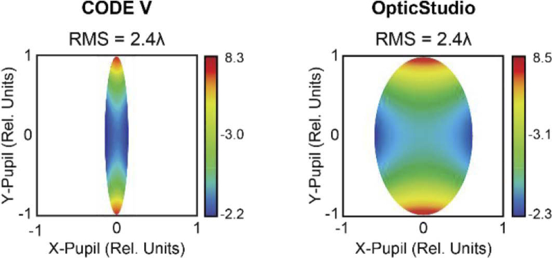
Piston and tilt were removed from all calculated wavefront maps and their root-mean-squared (RMS) values. Oblique astigmatism is reported in all figures using the Optical Society of America [24] and American National Standard Institutes [ANSI Z80.28-2004] conventions, in which the 3rd Zernike term corresponds to the 6th Fringe Zernike coefficients in OpticStudio divided by the normalization factor . Pupil distortion values, inferred from the wavefront maps generated by OpticStudio, are not thought to be accurate and thus should be considered just a coarse approximation. In fact, the comparison of wavefront map generated using the same optical setups using two different ray tracing software, can provide strikingly different pupil distortion, as illustrated in Fig. 7.
Fig. 7.
Code V (Synopsys, Pasadena, CA, USA) and OpticStudio wavefront map comparison for a reflective afocal relay formed by two spherical mirrors illuminated with 500 nm light, , , , , , , and .
5. Results
5.1. Reflective afocal relay optimized for zero vergence
When considering the zero vergence case, the numerical minimization of the field-averaged wavefront variance yields two solutions for each desired linear astigmatism amplitude, shown on Table 3. These solutions show symmetries that can be gleaned from the formulae for , the dominant non-rotationally symmetric aberration, can only cancel when Similarly, the cancellation of requires (see Table 1 with ).
Table 3. Numerical tilt solutions that minimize the field-averaged third order wavefront variance in an afocal reflective telescope formed by two concave spherical mirrors with parameters: and . The square root of the wavefront variances was calculated using the small angle approximation and the exact formulae in Table 1, expressed in units of waves.
| Solution # | 1 | 2 | 1 | 2 | ||
| 0.0 | -13.5 | 13.5 | 0.0 | -55.9 | 55.9 | |
| 0.0 | 13.5 | -13.5 | 0.0 | 55.9 | -55.9 | |
| 0.0 | 19.1 | 19.1 | 0.0 | 76.3 | 76.3 | |
| 0.0 | 9.5 | 9.5 | 0.0 | 38.2 | 38.2 | |
| 0.023 | 0.007 | 0.007 | 0.093 | 0.027 | 0.027 | |
| 0.023 | 0.023 | 0.023 | 0.093 | 2.954 | 2.954 | |
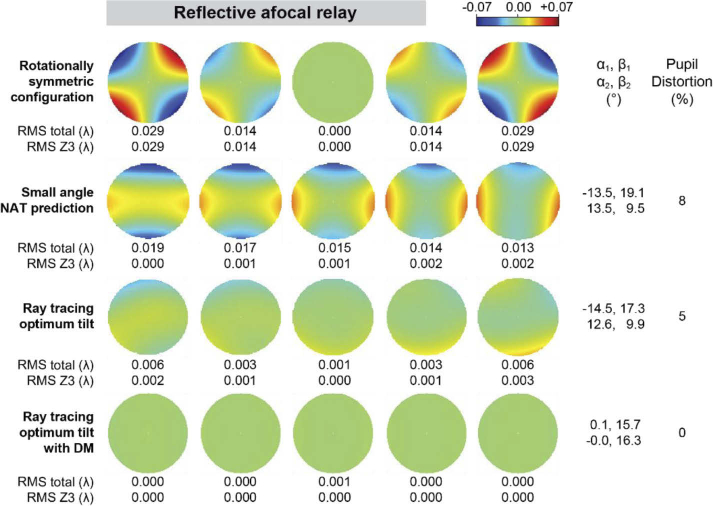
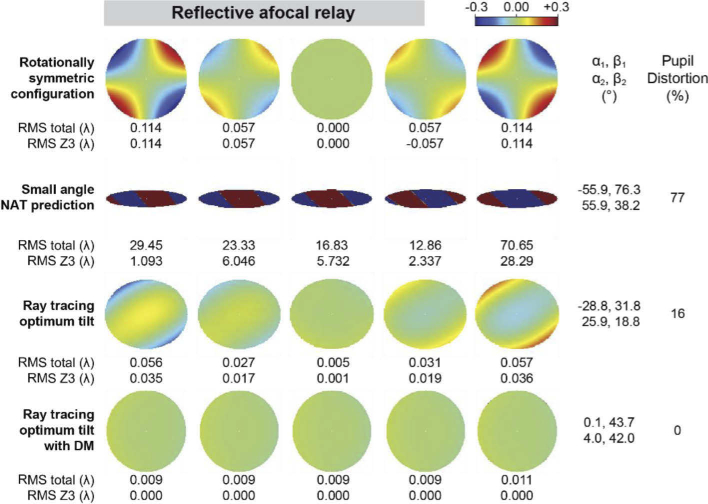
The wavefronts and metrics resulting from the ray tracing can be seen in Fig. 8 and Fig. 9 for 0.07 and 0.28 waves of linear oblique astigmatism simulating the dynamic distortion of two different resonant scanners, respectively. The top row in these figures correspond to the rotationally symmetric initial configuration (i.e., ), in which the dominant aberration is the resonant scanner linear oblique astigmatism. The second rows show the performance when the spherical mirrors are tilted as per the first solution in Table 3. The third rows show the performance when the spherical mirror tilts are optimized by the OpticStudio starting with zero tilts. For 0.07 waves of linear astigmatism, the tilts calculated using third order nodal aberration theory and the paraxial approximation are within 5% of the angles found by OpticStudio, which does not use the paraxial approximation and accounts for higher order aberrations. The corresponding pupil distortion is 8% for the small angle NAT prediction, 7% for the ray tracing optimization and less than 1% for the ray tracing solution with a deformable mirror compensating field-constant aberrations.
Fig. 8.
Wavefront maps and metrics for an afocal relay formed by two spherical mirrors for -2, -1, 0, 1, and 2° field points, with 0.07 waves of oblique astigmatism at the field edge, assuming zero vergence (i.e., infinite conjugates).
Fig. 9.
Wavefront maps and metrics for an afocal relay formed by two spherical mirrors for -2, -1, 0, 1, and 2° field points, with 0.28 waves of oblique astigmatism at the field edge, assuming zero vergence (i.e., infinite conjugates).
The small angle approximation NAT calculated tilts provide a poor starting solution for compensating the 0.28 waves of resonant scanner linear astigmatism. In fact, it increases the wavefront RMS by more than an order of magnitude, also inducing very large pupil distortion (77%). This is not surprising, given that the calculated tilts are too large for the small angle approximation to be valid. Ray tracing optimization, however, reduces the linear astigmatism while keeping all other aberrations low. In this case, the inclusion of the deformable mirror in the optimization delivers wavefront RMS at all field points lower than λ/100 with less than λ/1000 of linear astigmatism, and negligible pupil distortion (<1%) despite spherical mirror tilts being as large as 40°.
5.2. Refractive afocal relay optimized for zero vergence
For a refractive afocal relay formed by two plano-convex singlets, the numerical minimization of the field-averaged wavefront variance yields three solutions for each of the linear astigmatism amplitudes considered (shown on Table 4). These solutions show symmetry that can be gleaned from the formulae in Table 2 for linear and constant astigmatism ( and ), the dominant non-rotationally symmetric aberrations, which cancel when and , respectively. These relations have opposite signs to their reflective relay equivalent.
Table 4. Numerical tilt solutions that minimize the field-averaged third order wavefront variance in an afocal refractive telescope formed with by two thin plano-convex lenses with parameters: , , , , , and . The square root of the wavefront variances was calculated using the small angle approximation and the exact formulae in Table 1, expressed in units of waves.
| Solution # | 1 | 2 | 3 | 1 | 2 | 3 | ||
| 0 | 2.5 | -2.5 | 0.0 | 0 | 12.3 | -12.3 | 0.0 | |
| 0 | 2.5 | -2.5 | 0.0 | 0 | 12.3 | -12.3 | 0.0 | |
| 0 | -4.4 | -4.4 | -3.3 | 0 | -17.7 | -17.7 | -5.7 | |
| 0 | 2.2 | 2.2 | 1.7 | 0 | 8.8 | 8.8 | 2.9 | |
| 0.023 | 0.007 | 0.007 | 0.009 | 0.093 | 0.038 | 0.038 | 0.073 | |
| 0.023 | 0.007 | 0.007 | 0.009 | 0.093 | 0.042 | 0.042 | 0.073 | |
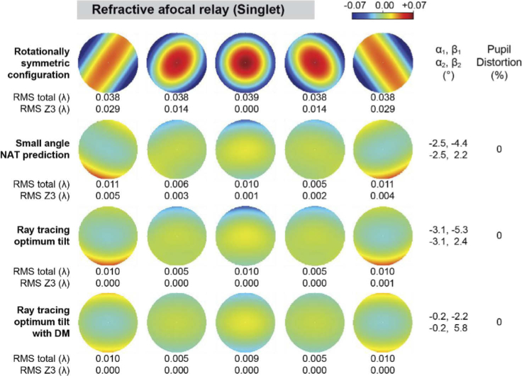
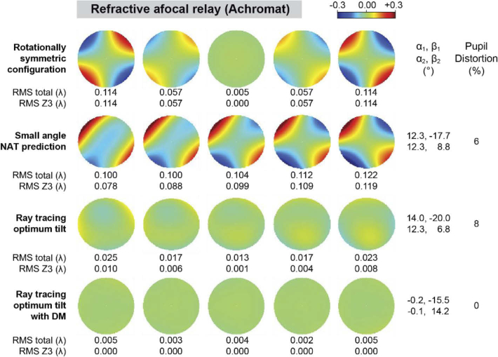
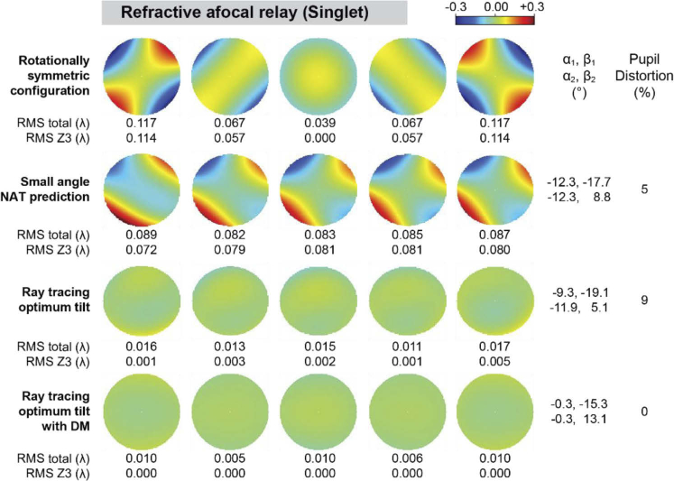
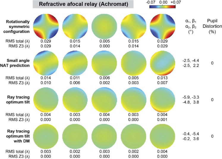
The wavefronts and metrics resulting from the ray tracing are shown in Fig. 10–Fig. 13 for the 0.07 and 0.28 waves of linear astigmatism, first for a relay formed by plano-convex singlet lenses, and then for a relay formed by commercial achromatic doublets. The rows in these figures match those from the reflective system. In the plano-convex singlet relay, the rotationally symmetric system is dominated by the linear astigmatism and other field-varying aberrations. The tilts predicted by the small angle NAT approximation are reasonable initial solutions that are within 20 and 32% of those found by the ray tracing optimizer for 0.07 and 0.28 waves of linear astigmatism, respectively. The ray tracing solutions deliver λ/60 wavefront RMS or better across the field of view, and no substantial improvement when using a deformable mirror. Pupil distortion is negligible (<1%) in all configurations for the 0.07 waves of linear astigmatism, but not for 0.28 waves (9%), which requires the use of a deformable mirror to achieve both good wavefront correction and negligible pupil distortion. The achromatic doublet relay shows similar performance to that of the plano-convex lens relays, suggesting that the singlet NAT derivations can be used to generate initial solutions for more complex lenses. Interestingly, the refractive element tilts are ∼3-4 times lower than their reflective equivalents to achieve the same linear astigmatism, due to the ∼15 times larger surface coefficients and ∼2 times smaller field displacement vectors in our application.
Fig. 10.
Wavefront maps and metrics for an afocal relay formed by two plano-convex lenses for -2, -1, 0, 1, and 2° field points, with 0.07 waves of oblique astigmatism at the field edge, assuming zero vergence (i.e., infinite conjugates).
Fig. 13.
Wavefront maps and metrics for an afocal relay formed by two achromatic doublets (ACT508-400-A, Thorlabs, and DLB-50-800PM, Laser 2000) for -2, -1, 0, 1, and 2° field points, with 0.28 waves of oblique astigmatism at the field edge, assuming zero vergence.
Fig. 11.
Wavefront maps and metrics for an afocal relay formed by two plano-convex lenses for -2, -1, 0, 1, and 2° field points, with 0.28 waves of oblique astigmatism at the field edge, assuming zero vergence (i.e., infinite conjugates).
Fig. 12.
Wavefront maps and metrics for an afocal relay formed by two achromatic doublets (ACT508-400-A, Thorlabs, and DLB-50-800PM, Laser 2000) for -2, -1, 0, 1, and 2° field points, with 0.07 waves of oblique astigmatism at the field edge, assuming zero vergence.
5.3. Reflective afocal relay optimized for a vergence range
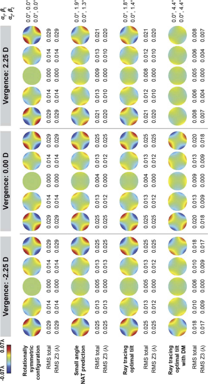
The numerical minimization of the vergence and field-averaged wavefront variance, defined in Eq. (13), yields only one solution for the desired linear astigmatism amplitude (, , and ). Interestingly, the small angle approximation NAT solution and the ray tracing optimal solutions (with and without using a DM) have much smaller angles than those for the zero vergence case, achieving a more modest level of correction that varies between 50 and 70% across vergences and field points (Fig. 14).
Fig. 14.
Wavefront maps and metrics for an afocal relay formed by two spherical mirrors for -2, -1, 0, 1, and 2° field points, with 0.07 waves of oblique astigmatism at the field edge, for three vergences.
6. Summary
Here we illustrated how third order nodal aberration theory can be used to estimate initial tilting and/or decentering of optical elements to be refined by ray tracer optimizers. The first step in this broadly applicable approach is to analytically derive the field displacement vectors and the aberration coefficients for rotationally symmetric surfaces, together with a symbolic calculator to obtain a small angle approximation of the field-averaged wavefront variance that is then analytically or numerically minimized. This method, which can be applied to any pupil and field geometries, can be thought of a generalization of that by Zhong and Gross, in which the authors only consider a single field point [15]. Moreover, our approach is the continuous equivalent of what ray tracer optimizers do, by minimizing merit functions that discretely sample the continuous field-averaged wavefront variance. The main difference between the two, is that ray tracing software traces real, rather than paraxial, rays and includes higher order aberrations. Just like the merit function in ray tracers can be tailored to a particular optical design problem, the function to minimize analytically (or numerically) can be equally modified, as we demonstrated by calculating the field-averaged wavefront variance for a field of view that is a line segment and then averaging across a vergence range. Finally, and despite the small angle approximation, the analytical approach provides insight and can reveal all the solutions and their symmetry. This might not be trivial to find with ray tracing optimization without systematic exploration of the multi-dimensional design parameter space.
When the proposed design method is applied to the compensation of the dynamic distortion of a resonant scanner, it guided us to solutions that compensate modest linear astigmatism amplitudes using reflective or refractive afocal relays, while keeping all other aberrations well beyond the diffraction limit (λ/14 wavefront RMS). This is of practical significance, because it indicates that the linear astigmatism induced by resonant scanners in high resolution optical systems can be cancelled or mitigated just by tilting existing optical elements, even if multiple conjugates are used simultaneously.
Acknowledgments
The authors would like to thank Dr. John Rogers for helpful nodal aberration discussion and guidance.
Funding
Research to Prevent Blindness10.13039/100001818 (Challenge Grant); National Eye Institute10.13039/100000053 (P30EY026877, R01EY025231, R01EY028287, R01EY031360).
Disclosures
The content is solely the responsibility of the authors and does not necessarily represent the official views of the National Institutes of Health.
Data availability
Data underlying the results presented in this paper are not publicly available at this time but may be obtained from the authors upon reasonable request.
References
- 1.Tsien R. Y., Bacskai B. J., “Video-rate confocal microscopy,” in Handbook of biological confocal microscopy (Springer, 1995), pp. 459–478. 10.1007/978-1-4757-5348-6_29 [DOI] [Google Scholar]
- 2.Zhao B., Howard-Knight J., Humphris A., Kailas L., Ratcliffe E., Foster S., Hobbs J., “Large scan area high-speed atomic force microscopy using a resonant scanner,” Rev. Sci. Instrum. 80(9), 093707 (2009). 10.1063/1.3227238 [DOI] [PubMed] [Google Scholar]
- 3.Sheppard C., Kompfner R., “Resonant scanning optical microscope,” Appl. Opt. 17(18), 2879–2882 (1978). 10.1364/AO.17.002879 [DOI] [PubMed] [Google Scholar]
- 4.Dubra A., Sulai Y., “Reflective afocal broadband adaptive optics scanning ophthalmoscope,” Biomed. Opt. Express 2(6), 1757–1768 (2011). 10.1364/BOE.2.001757 [DOI] [PMC free article] [PubMed] [Google Scholar]
- 5.Hammer D. X., Ferguson R. D., Bigelow C. E., Iftimia N. V., Ustun T. E., Burns S. A., “Adaptive optics scanning laser ophthalmoscope for stabilized retinal imaging,” Opt. Express 14(8), 3354–3367 (2006). 10.1364/OE.14.003354 [DOI] [PMC free article] [PubMed] [Google Scholar]
- 6.Ferguson R. D., Zhong Z., Hammer D. X., Mujat M., Patel A. H., Deng C., Zou W., Burns S. A., “Adaptive optics scanning laser ophthalmoscope with integrated wide-field retinal imaging and tracking,” J. Opt. Soc. Am. A 27(11), A265–A277 (2010). 10.1364/JOSAA.27.00A265 [DOI] [PMC free article] [PubMed] [Google Scholar]
- 7.Zhao Y., Chen Z., Ding Z., Ren H., Nelson J. S., “Real-time phase-resolved functional optical coherence tomography by use of optical Hilbert transformation,” Opt. Lett. 27(2), 98–100 (2002). 10.1364/OL.27.000098 [DOI] [PubMed] [Google Scholar]
- 8.Wieser W., Draxinger W., Klein T., Karpf S., Pfeiffer T., Huber R., “High definition live 3D-OCT in vivo: design and evaluation of a 4D OCT engine with 1 GVoxel/s,” Biomed. Opt. Express 5(9), 2963–2977 (2014). 10.1364/BOE.5.002963 [DOI] [PMC free article] [PubMed] [Google Scholar]
- 9.Huber R., Wojtkowski M., Fujimoto J. G., Jiang J., Cable A., “Three-dimensional and C-mode OCT imaging with a compact, frequency swept laser source at 1300 nm,” Opt. Express 13(26), 10523–10538 (2005). 10.1364/OPEX.13.010523 [DOI] [PubMed] [Google Scholar]
- 10.Akondi V., Kowalski B., Burns S. A., Dubra A., “Dynamic distortion in resonant galvanometric optical scanners,” Optica 7(11), 1506–1513 (2020). 10.1364/OPTICA.405187 [DOI] [PMC free article] [PubMed] [Google Scholar]
- 11.Thompson K., “Description of the third-order optical aberrations of near-circular pupil optical systems without symmetry,” J. Opt. Soc. Am. A 22(7), 1389–1401 (2005). 10.1364/JOSAA.22.001389 [DOI] [PubMed] [Google Scholar]
- 12.Schmid T., Rolland J. P., Rakich A., Thompson K. P., “Separation of the effects of astigmatic figure error from misalignments using Nodal Aberration Theory (NAT),” Opt. Express 18(16), 17433–17447 (2010). 10.1364/OE.18.017433 [DOI] [PubMed] [Google Scholar]
- 13.Fuerschbach K., Rolland J. P., Thompson K. P., “Theory of aberration fields for general optical systems with freeform surfaces,” Opt. Express 22(22), 26585–26606 (2014). 10.1364/OE.22.026585 [DOI] [PubMed] [Google Scholar]
- 14.Shi H., Jiang H., Zhang X., Wang C., Liu T., “Analysis of nodal aberration properties in off-axis freeform system design,” Appl. Opt. 55(24), 6782–6790 (2016). 10.1364/AO.55.006782 [DOI] [PubMed] [Google Scholar]
- 15.Zhong Y., Gross H., “Initial system design method for non-rotationally symmetric systems based on Gaussian brackets and Nodal aberration theory,” Opt. Express 25(9), 10016–10030 (2017). 10.1364/OE.25.010016 [DOI] [PubMed] [Google Scholar]
- 16.Gu Z., Yan C., Wang Y., “Alignment of a three-mirror anastigmatic telescope using nodal aberration theory,” Opt. Express 23(19), 25182–25201 (2015). 10.1364/OE.23.025182 [DOI] [PubMed] [Google Scholar]
- 17.Cao C., Liao S., Liao Z., Bai Y., Fan Z., “Initial configuration design method for off-axis reflective optical systems using nodal aberration theory and genetic algorithm,” Opt. Eng. 58(10), 105101 (2019). 10.1117/1.OE.58.10.105101 [DOI] [Google Scholar]
- 18.Papa J. C., Howard J. M., Rolland J. P., “Starting point designs for freeform four-mirror systems,” Opt. Eng. 57(10), 101705 (2018). 10.1117/1.OE.57.10.101705 [DOI] [Google Scholar]
- 19.Hopkins H. H., Wave theory of aberrations (Clarendon Press, 1950). [Google Scholar]
- 20.Thompson K. P., “Aberration fields in tilted and decentered optical systems,” (The University of Arizona., 1980). [Google Scholar]
- 21.Thompson K. P., Schmid T., Cakmakci O., Rolland J. P., “Real-ray-based method for locating individual surface aberration field centers in imaging optical systems without rotational symmetry,” J. Opt. Soc. Am. A 26(6), 1503–1517 (2009). 10.1364/JOSAA.26.001503 [DOI] [PubMed] [Google Scholar]
- 22.Welford W. T., Aberrations of optical systems (CRC Press, 1986). [Google Scholar]
- 23.Rogers J. R., “Aberrations of Unobscured Reflected Optical Systems,” Ph.D. Dissertation (University of Arizona, 1983). [Google Scholar]
- 24.Thibos L. N., Applegate R. A., Schwiegerling J. T., Webb R., “Standards for reporting the optical aberrations of eyes,” in Vision science and its applications, (Optical Society of America, 2000), SuC1. [Google Scholar]
Associated Data
This section collects any data citations, data availability statements, or supplementary materials included in this article.
Data Availability Statement
Data underlying the results presented in this paper are not publicly available at this time but may be obtained from the authors upon reasonable request.


