Abstract
The Talbot-Lau grating interferometer enables refraction based imaging with conventional X-ray tubes, offering the promise of a new medical imaging modality. The fringe contrast of the normal incidence interferometer is however insufficient at the >40 keV photon energies needed to penetrate thick body parts, because the thin absorption gratings used in the interferometer become transparent. To solve this problem we developed a new interferometer design using gratings at glancing incidence. For instance, using 120 μm thick Au gratings at 10° incidence we increased several fold the interferometer contrast for a spectrum with ~58 keV mean energy. Tests of DPC-CT at 60–80kVp using glancing angle interferometers and medically relevant samples indicate high potential for clinical applications. A practical design for a slot-scan DPC-CT system for the knee is proposed, using glancing angle gratings tiled on a single substrate.
Keywords: X-ray phase contrast, Talbot-Lau interferometer
1. INTRODUCTION
X-ray differential phase-contrast (DPC) or refraction based imaging with Talbot-Lau grating interferometers has the potential to become a new medical imaging modality, offering higher soft tissue contrast and spatial resolution than that obtained with conventional attenuation based imaging [1], For instance, recent analysis suggests that DPC-CT could enable the detection of small lesions in soft tissue, which is not possible with other imaging modalities [2]. New bone imaging modalities may also be possible [3].
The Talbot-Lau interferometer consists of three micro-period gratings: ‘source’, ‘beam-splitter’, and ‘analyzer’ [1]. The source and analyzer are absorption gratings typically made of Au, while the beam-splitter is a thin phase grating typically made of Si or Ni. To enable imaging of thick body parts the interferometer must first work at high energy. For instance we are developing DPC imaging for the knee, for which conventional radiography is done at 60–65 kVp (40–45 keV mean spectral energy) and CT at 80–90 kVp (55–60 keV mean energy).
In addition, the interferometer must be very sensitive to small X-ray angular changes to enable refraction imaging with acceptable dose. The sensitivity is determined by two parameters: the fringe contrast or ‘visibility’ V, and the angular resolution, W. The contrast is defined as V=(IBF−IDF)/(IBF+IDF). with IBF and IDF the ‘bright-field’ and the ‘dark-field’ intensity respectively, while W is given by the ratio between the interferometer period and the distance between the beam-splitter and analyzer grating [1,4], High contrast (in the ≥20% range approximately) is essential for medical DPC imaging, because the SNR in the DPC images improves rapidly with increasing contrast (e.g., as ~V2 in DPC-CT [5]). Good angular resolution (W ≤ several μ-radian) is also needed, because the X-ray refraction angles in soft tissue are in the sub μ-radian range [4]. The requirements for high contrast and angular resolution are more critical at high X-ray energy, because the refraction angles decrease with energy as ~1/E2.
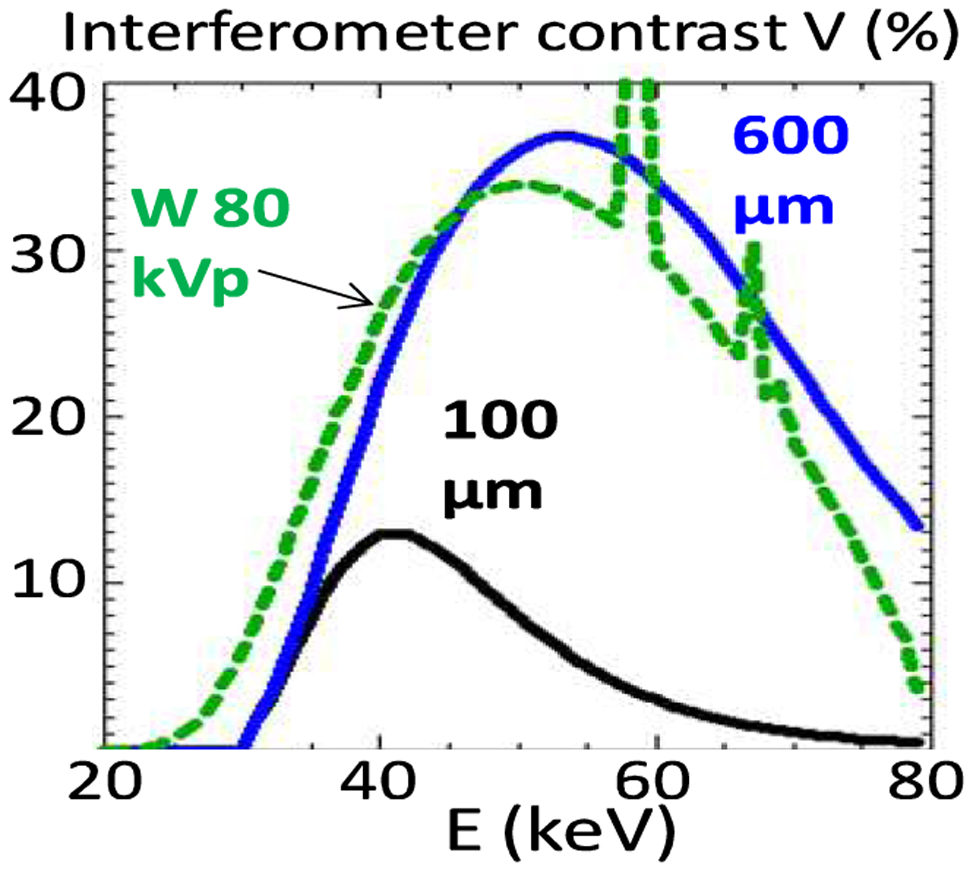
In summary, for DPC imaging of large body parts the Talbot-Lau interferometer must have ≥20% contrast at mean spectral energies ≥40 keV, while using gratings with ≤10 μm period. This is not possible however with the conventional normal incidence Talbot-Lau interferometer, because the thickness of few micron period absorption gratings is technologically limited to ~100 μm [6]. To illustrate this limitation, in Fig. 1 we plot the computed contrast of a first Talbot order (m=1), 5 μm period interferometer designed for 55 keV mean energy, and having 100 μm thick, 50% duty-cycle (opening to period ratio) Au gratings. Also plotted is the spectrum of an 80 kVp W anode tube after transmission through 2 mm Al, 75 μm Cu and 150 mm soft tissue. The maximal contrast is low and the contrast curve overlaps poorly with the tube spectrum, making for a spectrally averaged contrast of only 6%.
Figure 1.

Computed contrast of an m=1 interferometer of 55 keV design energy, for 100 μm thick Au gratings and for 600 μm thick gratings. Also shown is the computed spectrum of an 80 kVp W anode tube filtered with 2 mm Al, 75 μm Cu and 150 mm soft tissue.
2. METHODS
2.1. The Glancing Angle Talbot-Lau Interferometer
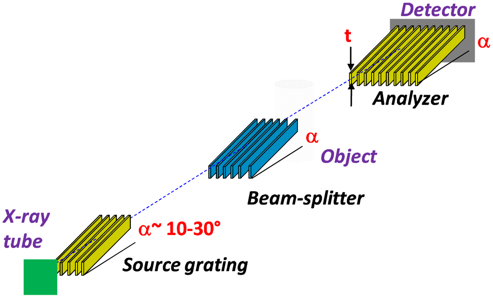
To overcome the above limitation we developed a glancing angle Talbot-Lau interferometer using gratings with the bars inclined at an angle α~10–30° along the beam direction, as in Fig. 2 [7]. The effect of inclining the gratings is to increase the effective absorber thickness from the normal incidence value t, to t/sin(α). Since the X-ray absorption increases exponentially with the thickness, this enables achieving high contrast at high energy using the existing ~100 μm thick gratings. The expected contrast improvement is illustrated in Fig. 1 with the computed contrast for the above interferometer assuming that the 100 μm Au gratings are inclined at an angle α~10° (600 μm effective thickness). The contrast strongly increases at high energy, leading to about a five-fold improvement in the spectrally averaged contrast.
Figure 2.

Layout of the glancing angle Talbot-Lau grating interferometer.
A limitation in the glancing angle design is that inclining the gratings reduces also the field of view in the vertical direction by of factor of sin(α). Thus, assuming a typical grating height of ~70–100 mm, the achievable vertical field of view is ~12–50 mm for angles in the 10–30° range. In addition, a limitation common to all grating interferometers is that the horizontal field of view is reduced (vignetted) by the narrow (few μm), but deep (~100 μm) grating openings. At glancing incidence this effect is more pronounced due to the increased effective depth of the openings.
2.2. High Energy Performance of the Glancing Angle Interferometer
For our experiments we used a ‘symmetrical’ interferometer setup in which all grating periods are equal and the beam splitter is placed mid-distance between the source and the analyzer; this geometry provides maximal angular resolution for a given interferometer length [4], We used two interferometers:
A 5.4 μm period m=3 interferometer having 100 μm thick Au gratings, 1.6 m total length, and operated at 18–30° glancing angle, with spectra having mean energy in the range 40–45 keV
A 10 μm period m=1 interferometer having 120 μm thick Au gratings, 2 m total length, and operated at 10–18° glancing angles, with spectra having mean energy in the range 55–58 keV
The gratings were made by Micro Works Inc., Germany [8] in 0.2–0.5 mm thick Si wafers and had 70 mm diameter. To obtain X-ray spectra with mean energy between 40 and 58 keV we used a W anode tube (1 mA/50 μm spot) at 60–80 kVp and immersed the samples in a water bath having thickness between 70 and 200 mm. These conditions were meant to simulate imaging of a large joint such as the knee, while using relatively small samples (the field of view of the interferometer at the sample being limited to 25×25 mm by the detector size and by the 1.7 object magnification). The samples were positioned ~150 mm behind the phase grating. The detector was a 150 μm thick, 42×42 mm CsI:Tl scintillator, viewed by a 36×36 mm, 64-bit cooled CCD, through an f/1 relay lens system. The spatial resolution of the X-ray imaging system at the sample was ~75 μm. The low efficiency of the lens coupled detector and the low current of the X-ray tube required using long exposures (30–40s) to acquire sufficient photon statistics.
The large increase in contrast at high energy with the glancing angle interferometer is illustrated in Fig.3. Fig. 3a and 3b show the Moiré fringe contrast obtained with the 5.4 μm interferometer and a 43 keV mean energy spectrum, at normal and at 18° incidence. At normal incidence the beam-splitter was an 8.5 μm thick Au grating, and at glancing incidence a 7 μm thick Ni grating. As seen, the glancing angle interferometer has several times the contrast of the normal incidence one.
Figure 3.

Moiré fringe contrast at 60 kVp/43 keV mean energy, with the 5.4 μm m=3 interferometer at normal incidence (a), and at 18° incidence (b). c) Moiré contrast with the 10 μm period m=1 interferometer at 80 kVp/58 keV mean energy and 10° incidence. The Moiré images are normalized (‘flat-fielded’) to background images obtained with the phase grating rotated at 90° (i.e. without phase effects); the images are plotted on an intensity scale from 0.5 to 1.5.
Even more encouraging for high energy DPC imaging is the result in Fig. 3c, which shows the Moiré contrast obtained at 80 kVp with the 10 μm period m=1 interferometer at 10° incidence. The spectrum was filtered with 2 mm Al, 0.65 μm Cu, and 200 mm water, to obtain a mean energy of ~58 keV. The 40–60 keV range of mean energies is particularly difficult for Talbot-Lau interferometry, because the Au X-ray absorption is low below 80 keV. The glancing angle setup enabled nevertheless achieving over 30% contrast even in this difficult region.
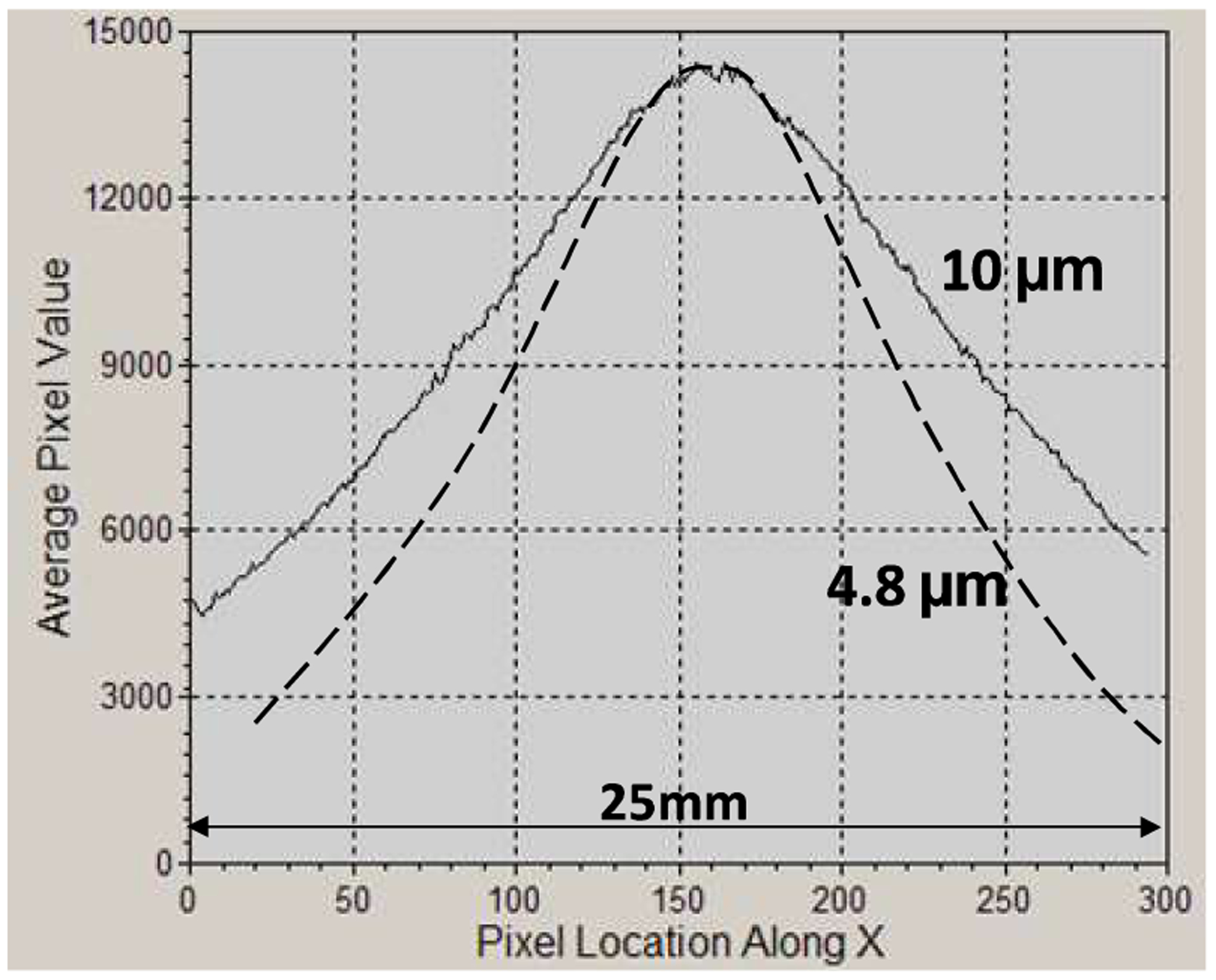
Together with the contrast increase the vertical field reduction at glancing incidence is also apparent in Fig. 3. Further on, the horizontal field of view vignetting at glancing incidence is illustrated in Fig. 4, which plots the horizontal intensity profile obtained with the 10 μm interferometer at 80 kVp/55 keV and at 10° glancing angle. The FWHM of the profile is only ~18 mm. For a smaller period/higher-m interferometer the FWHM further decreases, as illustrated by the horizontal intensity profile for a m=3, 2 m long interferometer having 4.8 μm period, 100 μm thick Au gratings at 10° angle.
Figure 4.

Horizontal (perpendicular to the grating bars in Fig. 2) intensity profiles for symmetric interferometers of 10 μm and of 4.8 μm period, having 2m length, and operated at 80 kVp/55 keV and 10° incidence angle. The FWHM is 18 mm for 10 μm period and 12.5 mm for 4.8 μm period.
The X-ray transmission of the glancing incidence interferometer is in the 20% range; for instance we measured 21% peak transmission with the 5.4 μm interferometer at 18°, for a spectrum with 55 keV mean energy. The transmission could be increased by a few percent using thinner grating substrates than in our experiments.
Lastly, as seen in Fig. 3, the fringe pattern becomes slightly distorted as the glancing angle decreases; this makes difficult completely removing low frequency Moiré fringes from the interferometric image. However, this effect does not significantly affect the phase-contrast imaging and could eventually be corrected, as further discussed.
3. EXPERIMENTAL RESULTS
3.1. Joint Phantom DPC-CT
For an assessment of the capability of our interferometer to discriminate materials similar to joint soft tissues we used a phantom fashioned after the model discussed in [9] and consisting of concentric cylindrical layers of water, PMMA, Al and nylon, simulating joint fluid, cartilage, cortical, and trabecular bone, respectively (Fig. 5). To emulate imaging conditions similar to a large joint the phantom was immersed in a thick water bath, with the water filling the interstices between layers.
Figure 5.

(a)–(b) Attenuation and DPC CT images of joint phantom in water, obtained with a 60 kVp/43 keV mean energy spectrum and the 5.4 μm interferometer at 30° glancing angle, (c)–(d) Attenuation and DPC radiographs of the phantom obtained with a 80 kVp/58 keV mean energy spectrum and the 10 μm interferometer at 10° glancing angle.
Cone-beam CT images of the phantom obtained at 60 kVp/43 keV mean energy with the 5.4 μm period interferometer at 30° are shown in Fig. 5a and 5b. The data was obtained using 200 CT angles with 1° step, 8 phase steps per angle and 30s exposure per step. The results show that DPC-CT has superior discrimination capability for soft tissue like materials at high energy. For instance, DPC-CT discriminates PMMA (cartilage) from water, while attenuation CT does not. The nylon/water, and in particular the nylon/PMMA contrast is also superior in DPC-CT. In addition, fine details such as the thin interfaces between the layers have better contrast in DPC-CT. The 80 kVp DPC radiograph of the phantom immersed in 200 mm water also shows superior contrast compared to the attenuation one: the PMMA layer is discriminated in the DPC image but not in the attenuation one, and the nylon/water contrast is also strongly increased.
3.2. Bone Phase Contrast Imaging
Bone poses a major challenge to medical DPC-CT because the strong small angle scattering (USAXS) in bone can lead to a substantial loss of interferometer contrast, to the point where DPC-CT in the presence of bone is no longer possible [10]. The high contrast of the glancing angle interferometer at high energy makes nevertheless possible phase contrast imaging in the presence of bone. The reason is twofold. First, at high enough energy the bone scatter decreases. Secondly, the initial contrast of the glancing angle interferometer is high enough that even after traversing a thick bone layer the X-rays remain sufficiently coherent to allow phase contrast imaging. This point is illustrated in Fig. 6 with attenuation and DPC images of a ~40 mm diameter veal bone embedded in a whole veal leg, having ~120 mm thick muscle. The DPC image shows the fine osteon structure and possibly the periosteum layer of the cortical bone, which are not distinguishable in the attenuation image.
Figure 6.

80 kVp attenuation and DPC radiographs of a fresh veal leg of ~120 mm thickness, containing a ~40 mm diameter bone with 4–5 mm thick cortical bone layer.
3.3. Soft Tissue DPC-CT
The glancing angle interferometer enabled also obtaining first DPC-CT images of a human joint with energetic X-ray spectra. Due to field of view limitations we used a human finger PIP joint of ~23 mm diameter, immersed in a 25 mm plastic vial. The vial was filled with a 60%–40% water ethanol mixture to preserve the tissue and further immersed in a thick water bath to produce an energetic transmitted spectrum. The CT parameters were the same as for the joint phantom experiments.
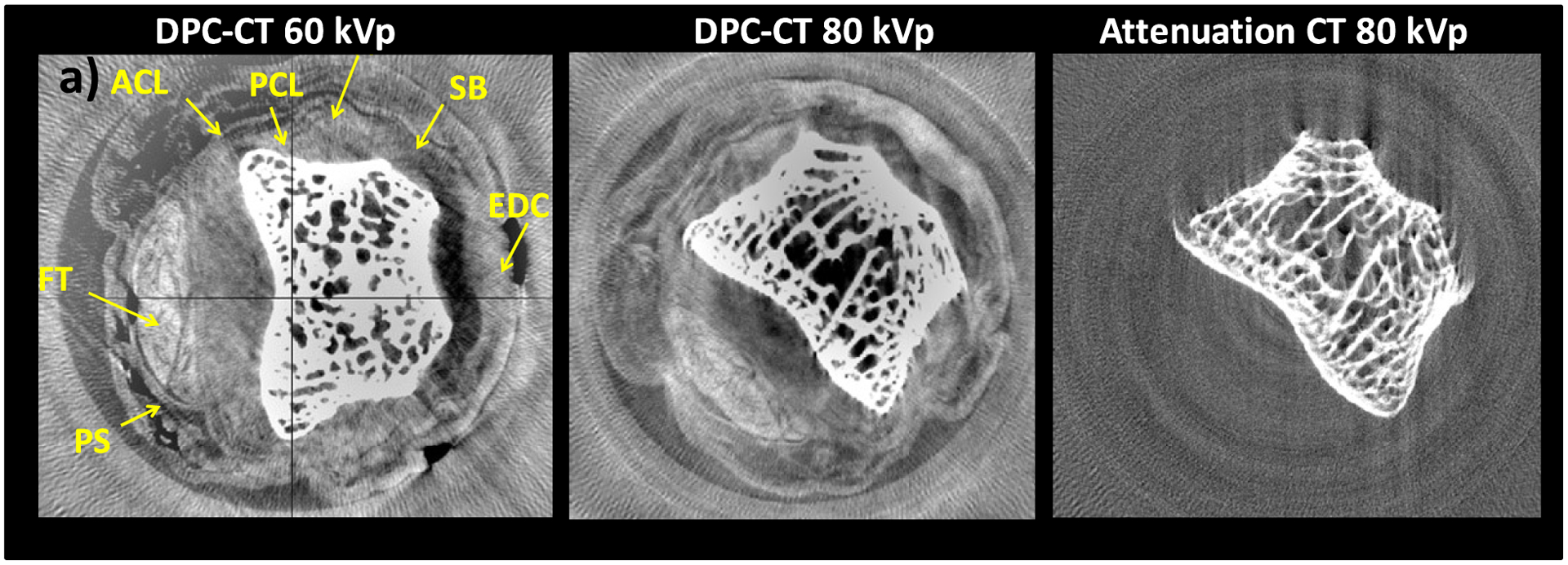
Fig. 7 shows DPC-CT and attenuation CT images of the joint, obtained with the 5.4 μm and the 10 μm glancing angle interferometers at 60 and 80 kVp. Although noisy, the DPC-CT image shows soft tissue contrast at both 60 kVp and 80 kVp, while the attenuation CT image does not at either energy. The combination of soft tissue contrast and high spatial resolution in DPC-CT enables visualizing anatomical detail such as the flexor tendon (FT), the volar plate (FP), or the extensor digitorum communis (EDC).
Figure 7.

a) 60 kVp/40 keV DPC-CT image of human finger PIP joint obtained with 5.4 μm interferometer at 30°. b) 80 kVp/50 keV DPC-CT image obtained with 10 μm interferometer at 18°. c) Attenuation image corresponding to b).
The 80 kVp DPC image has somewhat less soft tissue contrast compared to the 60 kVp one, as expected from the decrease in refraction angles with energy and from the lower angular sensitivity of the 10 μm interferometer compared to the 5.4 μm one. Nevertheless, it is encouraging that it is possible to image soft tissues at high energy also with an interferometer having larger period gratings and operating in the first Talbot order. This because larger period gratings can be made thicker, and because for a broad spectrum such as produced by a high kVp W tube the maximal interferometer contrast obtains in the first order.
The high frequency noise in the DPC-CT images appears to be due mainly to imperfections in the beam-splitter grating, while the low frequency noise appears due to slow system phase changes. These effects are amplified by our long exposures, which make inaccurate subtracting the phase background measured at the beginning or at the end of a CT scan.
4. DISCUSSION
The above results show that the glancing angle grating interferometer (GAI) offers a good solution for DPC imaging in the difficult region of 40–60 keV mean energy. Calculations further indicate that due to the increase in the Au absorption above 80 keV, this design offers high interferometer contrast up to ~150 kVp. In addition, encouraging for medical applications is that the soft tissue DPC contrast is superior to that obtained in the attenuation one even at high energy, and that the glancing angle interferometer enables DPC imaging even in the presence of bone.
The combination of soft tissue contrast and high spatial resolution make the GAI of interest for clinical DPC imaging of thick body parts. The knee joint would be a good place to start studying clinical DPC imaging, because the knee can be kept fixed for relatively long periods of time and because physiological movement is less of an issue. A DPC-CT system for the knee should work in principle with a spectrum and patient exposure similar to that in conventional CT (80–90 kVp and < few hundred mA·s per scan, respectively [11]).
The GAI solves the problem of the high energy contrast. Further on, the vertical field of view limitation of this instrument may be less constraining for knee CT, because imaging a 20–25 mm vertical region-of-interest centered on the joint space may be sufficient for most diagnostic purposes. However, the horizontal FOV must be much large. Assuming a typical knee diameter of ~150 mm and an object magnification around 1.5, a FOV ≥220 mm would be needed at the detector for full cone-beam CT. As mentioned, the strong lateral vignetting of the glancing angle interferometer prevents however covering more than 10–20 mm with a single grating.
The main question in the design of a glancing angle DPC-CT system is thus how to superimpose or ‘tile’ the gratings, so as to cover a large FOV in the horizontal direction. It would be relatively easy to tile the gratings with the bars perpendicular to the CT axis, as proposed in [6], However, as discussed in Ref. 12, the optimal configuration for DPC-CT is with the grating bars parallel the CT axis, as in Fig. 2.
The solution we propose consists in using a grating array consisting of multiple ‘sub-gratings’ with slightly rotated lines and made on a single substrate or wafer. All the sub-gratings have equal period and width; the width is equal or less the FWHM of their vignetting curve (e.g., 10 mm for a 10 μm period grating at 10° angle). The rotation angle follows the central ray direction for each sub-grating. In this way the incident X-rays ‘see’ an array of collimators that are with good approximation aligned to the ray direction, thus minimizing the vignetting. For instance, a 6” Si wafer would accommodate 12 sub-gratings of 10 mm width and 90 mm height, giving a FOV at the detector of 120 mm width and 30 mm height, at a glancing angle of 20°. Two such wafers side by side would cover a contiguous FOV 240 mm wide, sufficient for full cone-beam CT.
The major advantage in this solution is that the sub-gratings are aligned with nanometer precision through the lithographic manufacturing process, thus avoiding the need for complex and costly positioning systems. In addition, the period of the sub-gratings could be made to slowly vary across the field of view in order to compensate for the slight distortion of the Talbot pattern evident in Fig. 3.
In conclusion, the tiled grating GAI offers a path towards the development of high energy DPC systems, such as for knee CT. Such systems will require bright X-ray sources with spot size in the 100 μm range and detectors having simultaneously low noise, high efficiency, sensitivity, and large FOV in one dimension. Our estimates indicate that using such high performance sources and detectors in conjunction with single exposure phase-retrieval methods such as ‘interlaced scanning’ or Moiré interferometry [13,14], it might be possible to perform high resolution DPC-CT at dose comparable to conventional CT. Due to the several fold intensity decrease in the gratings the scan time will be however inherently longer. In order to minimize the dose and scan time it will be thus important to try and apply to DPC-CT novel image reconstruction methods developed for conventional CT, such as model-based statistical reconstruction, sparse sampling, or compressed sensing.
ACKNOWLEDGMENTS
Work supported by NIH grant 1R21EB012777-01A1.
REFERENCES
- [1].Pfeiffer F, Weitkamp T, Bunk O and David C, “Phase retrieval and differential phase-contrast imaging with low-brilliance”. X-ray sources Nature Physics 2, 258 (2006); [Google Scholar]; Momose A, Yashiro W, Takeda Y, Suzuki Y and Hattori T, “Phase Tomography by X-ray Talbot Interferometry for Biological Imaging”, Japanese J. Appl. Phys 45, 5254 (2006) [Google Scholar]
- [2].Tang X, Yang Y, and Tang S, “Characterization of imaging performance in differential phase contrast CT compared with the conventional CT: Spectrum of noise equivalent quanta NEQ(k)”, Med. Phys 39, 4467 (2012) [DOI] [PMC free article] [PubMed] [Google Scholar]
- [3].Potdevin G, et al. , “X-ray vector radiography for bone micro-architecture diagnostics”, Phys. Med. Biol 57 3451 (2012) [DOI] [PubMed] [Google Scholar]
- [4].Stutman D, Beck TJ, Carrino JA, and Bingham CO, “Talbot phase-contrast x-ray imaging for the small joints of the hand”, Phys. Med. Biol 56 5697 (2011) [DOI] [PMC free article] [PubMed] [Google Scholar]
- [5].Chen G-H., Zambelli J, Li K, Bevins N, and Qi Z, “Scaling law for noise variance and spatial resolution in differential phase contrast computed tomography”, Med. Phys 38, 584 (2011) [DOI] [PMC free article] [PubMed] [Google Scholar]
- [6].David C, Bruder J, Rohbeck T, Grünzweig C, Kottler C, Diaz A, Bunk O, and Pfeiffer F, “Fabrication of diffraction gratings for hard X-ray phase contrast imaging,” Microelectronic Engineering 84, 11721177, (2007). [Google Scholar]
- [7].Stutman D, Finkenthal M, Glancing angle Talbot-Lau grating interferometers for phase contrast imaging at high x-ray energy”, Appl. Phys. Lett 101, 091108 (2012) [DOI] [PMC free article] [PubMed] [Google Scholar]
- [8]. http://www.micro-works.de/
- [9].Anderson AE, Ellis BJ, Peters CL, Weiss JA, “Cartilage Thickness:Factors Influencing Multidetector CT Measurements in a Phantom Study”, Radiology 246, 133 (2008) [DOI] [PMC free article] [PubMed] [Google Scholar]
- [10].Li K, Bevins NB, Zambelli JN, and Chen G-H, “Feasibility of differential phase contrast CT for whole body imaging”, AIP Conf. Proc 1466, 175 (2012) [Google Scholar]
- [11].Zbijewski W, De Jean P, Prakash P, Ding Y, Stayman JW, Packard N, Senn R, Yang D, Yorkston J, Machado A, Carrino JA, and Siewerdsen JH, “A dedicated cone-beam CT system for musculoskeletal extremities imaging: Design, optimization, and initial performance characterization,” Med. Phys 38, 4700 (2011) [DOI] [PMC free article] [PubMed] [Google Scholar]
- [12].Olbinado Margie P., Harasse Sébastien, Yashiro Wataru, and Momose Atsushi “X-ray Talbot-Lau interferometer for high-speed phase imaging and tomography using white synchrotron radiation”, AIP Conf. Proc 1466, 266 (2012) [Google Scholar]
- [13].Zanette I,1,2, Bech M, Rack A, Le Duc G, Tafforeau P, David C, Mohr J, Pfeiffer F, and Weitkamp T, “Trimodal low-dose X-ray tomography”, PNAS 109, 10199 (2012) [DOI] [PMC free article] [PubMed] [Google Scholar]
- [14].Bevins Nicholas, Zambelli Joseph, Li Ke, and Qi Zhihua, “Multicontrast x-ray computed tomography imaging using Talbot-Lau interferometry without phase stepping”, Med. Phys 39, 424 (2012) [DOI] [PMC free article] [PubMed] [Google Scholar]


