

Abstract
Objectives.
This study evaluated the effect of dwell time (conventional or extended) and cooling protocol (fast or slow) of self-glaze firings on the flexural strength and crack propagation of a porcelain-veneered zirconia system.
Methods.
Bilayer disc-shaped samples were prepared (Vita VM9 + In-Ceram YZ) and divided according to the final thermal treatment: glaze firing followed by slow cooling (furnace opening at 200°C) (G-S) or fast cooling (furnace opening at 600°C) (G-F, manufacturer-recommended protocol), extended glaze firing (15 min of dwell time) followed by slow cooling (EG-S) or fast cooling (EG-F), or no thermal treatment (CTRL). Porcelain roughness (Ra and Rz) was measured before and after glaze firings. Color (ΔE00) and translucency (TP00) alteration were also evaluated. Flexural strength was measured with the piston-on-three-ball test and crack propagation analysis was performed after Vickers indentations. Complementary analyzes of crystalline phase and scanning electron microscopy were carried out.
Results.
Significant effect of dwell time was observed, with extended glaze leading to higher flexural strength and shorter crack lengths. Cracks of EG groups were observed to end in clusters of crystals. Color and translucency changed below perceptibility thresholds. All treatments led to a smoother surface and EG groups reached the lowest Rz values. An extra SiO2 peak was revealed in control and EG groups. No effect of cooling protocol was found.
Significance.
Extended glaze firing was able to improve the resistance to crack initiation and propagation of porcelain-veneered zirconia without clinically perceptible changes in optical properties.
Keywords: dental ceramics, porcelain fused to zirconia, cooling protocols, heat treatments, flexural strength
1. Introduction
Porcelain-veneered zirconia (PVZ) system is one of the best options for anterior and posterior single or multiple unit restorations, especially when enhanced esthetics is required. It combines both the zirconia’s mechanical properties and porcelain’s optical properties, [1–3] which make these restorations popular among dental professionals.
High fracture rates of the porcelain veneer layer were reported in clinical studies of PVZ crowns with up to 10-year follow-up [4–6] and in a systematic review. [7] Thereby, in the last few years, laboratorial procedures have been refined by adopting new processing protocols, such as slow cooling after the last firing and anatomically corrected frameworks. Rinke et al [8, 9] clinically followed PVZ crowns and metal-ceramic fixed dental prostheses (FDPs) fabricated using slow cooling and anatomic-shaped frameworks. The authors observed no difference in survival rates between the bilayer systems (metal-ceramic and PVZ). However, they observed less veneer chipping events on the metal-free restorations when compared to findings from previous studies. [4–6] Despite that, papers still report ceramic fractures as a current problem, particularly due to minor veneer chippings. [10–14]
Although a minor chipping does not lead to the replacement of the restoration, it still causes discomfort to patients and requires clinical intervention, such as polishing or filling. Porcelain’s susceptibility to fracture is related to multiple factors: overly thick or non-homogeneous porcelain layer thickness, [15, 16] inadequate framework design (non-anatomic, which leads to a lack of support to the veneer), [17–19] low strength and toughness of the porcelain, [20] inadequate ceramic firing, [21] defects caused by occlusal adjustment, [22] and incompatibility between framework and veneer thermal expansion coefficients [23–25]. In addition, fast cooling the restorations after the firing cycle also contributes to the development of residual thermal stresses and, consequently, increased fracture susceptibility [26, 27].
Annealing procedures are capable of relaxing residual stresses in glasses [28]. This procedure consists of maintaining the material at high constant temperatures – close to its glass transition temperature – during the time necessary to decrease its viscosity and allow molecular structural rearrangement, which results in stresses relaxation [29, 30]. Previous studies investigated the effect of annealing protocols [28, 31–36] or glaze firings [37–39] on mechanical properties of glass ceramics; most of them reported an increase in strength values [28, 36–38]. However, some of these proposed treatments seem unfeasible for dental laboratories, due to the long time required. In addition, metal oxides, responsible for the material color, may become unstable depending on the firing protocol performed [40, 41].
In this context, this study aimed to evaluate the effect of dwell time (conventional or extended) and cooling protocol (fast or slow) of glaze firings (self-glaze) on the flexural strength and resistance to crack propagation of a porcelain-veneered zirconia (PVZ) system. We designed definitive tests to determine which parameter dominants these mechanical properties by characterizing microstructural and surface changes. In addition, the optical properties were also tested to evaluate the esthetics feasibility of the treatments. The hypotheses tested were that 1) the extended glaze firing would improve the resistance to crack initiation and propagation, 2) as well as a slow cooling protocol, and 3) color and translucency would not be affected by glaze firing or cooling protocols.
2. Materials and Methods
2.1. Study design
This in vitro study evaluated two factors: dwell time (glaze or extended glaze), and cooling protocol (fast or slow). The response variables analyzed were flexural strength, crack length, roughness, color difference, and translucency. The materials used in this study are described in Table 1.
Table 1.
Description, commercial name and manufacturer, and composition of the materials used in the study
| Material | Commercial brand | Composition* |
|---|---|---|
| Yttria-stabilized tetragonal zirconia polycrystal (Y-TZP) | Vita In Ceram YZ (Vita Zahnfabrik, Bad Säckingen, Germany) | Zr2O3 (90-95%), Y2O3 (4-6%), HfO2 (1-3%), Al2O3 (0-1%), Pigments (0-1%) |
| Feldspathic ceramic | Vita VM9 (Vita Zahnfabrik, Bad Säckingen, Germany) | SiO2 (60–64%), Al2O3 (13–15%), K2O (7–10%), Na2O (4–6%), TiO2 (<0.5%), CeO2 (<0.5%), ZrO2 (0–1%), CaO (1–2%), B2O3 (3–5%), BaO (1–3%), SnO2 (<0.5%), Mg, Fe, and P oxides (<0.1%) |
| Modelling liquid | Vita VM Modelling Liquid (Vita Zahnfabrik, Bad Säckingen, Germany) | Ethanol and sodium hydroxide |
Manufacturer’s information
2.2. Samples preparation
Pre-sintered blocks of a 3 mol% yttria stabilized tetragonal zirconia (3Y-TZP) ceramic (In-Ceram YZ, Vita Zahnfabrik, Bad Säckingen, Germany) with dimensions of 20 mm × 19 mm × 15.5 mm were grinded to Ø18 mm cylinders with a #400 grit SiC paper under water cooling. The cylinders were cut into 1.2 mm thick discs (n = 88) using a low speed diamond saw (Isomet 1000, Buehler, Lake Bluff, USA). The surfaces to be porcelain-veneered were grinded with #220 SiC paper for 20 s on each axis (x and y) by a single operator. The opposite surface was polished with a #1200 grit SiC paper to 0.9 mm thick. The zirconia discs were ultrasonically cleaned in ethanol, dried, and sintered in a high-temperature furnace (Vita Zyrcomat 6000MS, Vita Zahnfabrik, Bad Säckingen, Germany) at 1530°C (heating rate: 200°C/h) as suggested by the manufacturer. The after sintering dimensions of the zirconia discs were Ø15 × 0.7 mm.
The discs were placed in a metallic mold for applying a 1.5 mm thick veneer layer. The feldspathic ceramic powder (VM9, Vita Zahnfabrik, Bad Säckingen, Germany) was mixed with the building liquid (Vita VM Modelling Liquid, Vita Zahnfabrik, Bad Säckingen, Germany) to form a slurry (1:1 proportion) that was poured into the metallic mold. The porcelain was condensed with manual vibration and the excess of water was removed with absorbent paper. The bilayer discs were removed from the mold and placed in a ceramic furnace (Vita Vacumat 6000MP, Vita Zahnfabrik, Bad Säckingen, Germany) for porcelain sintering, according to manufacturer’s instructions: pre-heating to 500°C per 6 min, heating up to 910°C at 55°C/min, vacuum during 7 min, cooling down to 800°C with furnace closed, and to 600°C with 25% of the furnace opened before totally open the furnace. Three firings were performed to all samples in order to compensate the porcelain shrinkage. After that, the porcelain surface was polished with #400, #600, and #1200 grit SiC papers under water cooling. The final thickness was 1.4 mm (porcelain veneer: 0.7±0.02 mm, zirconia: 0.7±0.02 mm).
After all polishing procedures, the samples were ultrasonically cleaned with ethanol, dried and randomly divided into four groups (n = 22) using a numeric sequence generated by the website random.org. Two groups were subjected to a glaze firing followed by fast or slow cooling, and two groups were subjected to an extended glaze firing followed by fast or slow cooling. One group (control) was not subjected to any firing after polishing. The four firing cycles for self-glaze are described in Table 2. The samples were removed from the firing base immediately after the furnace opening.
Table 2.
Experimental groups according to the thermal treatments
| Group | Thermal treatment | Initial temperature (°C) | Temperature increase rate (°C/min) | Final temperature (°C) | Heating bath dwell time (min) | Cooling |
|---|---|---|---|---|---|---|
| EG-F | Extended glaze firing | 500 | 80 | 900 | 15 | Fast* |
| FG-S | 500 | 80 | 900 | 15 | Slow** | |
| G-F*** | Glaze firing | 500 | 80 | 900 | 1 | Fast* |
| G-S | 500 | 80 | 900 | 1 | Slow** | |
| CTRL | No extra firing cycle | |||||
Fast cooling: cooling down to 800°C with closed furnace and to 600°C with the furnace 25% opened.
Slow cooling: furnace completely closed until 200°C.
Glaze firing protocol indicated for Vita VM9 by the manufacturer (Vita Zahnfabrik).
2.3. Color difference and translucency measurements
The samples were analyzed with a spectrophotometer (SP-60, X-Rite, Grand Rapids, USA) using the CIE L*a*b* color system (Commission Internationale de l’Éclairage). Each sample was measured three times over white (L* = 93.07, a* = −1.28, b* = 5.25) (LENETA Card – model 12H – Cor&Aparência, São Paulo, Brazil), black (L* = 27.94, a* = −0.01, b* = 0,03) (LENETA Card – model 12H – Cor&Aparência, São Paulo, Brazil), and gray (CIE-L* = 50.30, a* = −1.41, b* = −2.37) (Mennon gray cards, Mennon photographic and technical Co., Beijing, China) backgrounds, before and after glazing, to obtain the CIEL*a*b* values (L* = lightness axis, a* = green-red axis, and b* = blue-yellow axis). The average of the three measurements of each sample over each background was used for the calculations. A drop of a coupling agent (glycerol C3H8O3, refractive index 1.47) (Vetec Química Fina Ltda, Rio de Janeiro, Brazil) was used between the sample and the background to minimize light scattering [42] during the measurements.
The values obtained from gray background, measured before and after glazing, were used to calculate the samples’ color difference (ΔE00) with the CIEDE2000 formula (Equation 1). The perceptibility (ΔE00 > 0.81) and unacceptability (ΔE00 > 1.80) thresholds described by Paravina et al (2015) [43] were considered for clinical inference.
| (1) |
where ΔL′, ΔC′, and ΔH′ are the differences in lightness, chroma, and hue, respectively, for a pair of measurements (before and after thermal treatments). The rotation function RT accounts for the interaction between chroma and hue differences in the blue region. Weighting functions SL, SH, and SC adjust the total color difference for variation in the location of the color difference pair in L′, a′, b′ coordinates. The parametric factors KL, KC, and KH are correction terms for deviation from reference experimental conditions. In this study, these parametric factors of the CIEDE2000 formula were set as 1.
The translucency parameter (TP00) was also calculated with the CIEDE2000 formula (Equation 1). However, the pair of measurements used were the CTEL*a*b* parameters obtained from each sample over the white and black backgrounds, separately before and after the glazing firings. We considered the findings obtained by Salas et al (2018) [44] as clinical inference: a difference between two TP00 values (before and after glazing - ΔTP00) is perceptible when it reaches 0.62, and clinically unacceptable when it reaches 2.62.
2.4. Roughness analysis
The average roughness (Ra) and ten-point-mean roughness (Rz) were evaluated before and after the glaze firings with a SJ-410 roughness tester (Mitutoyo, Takatsu-Ku, Japan). The tests were performed with a 0.80 mm cutoff, 0.0001 μm resolution (8 μm range), 0.5 mm/s speed, and total length of 4 mm, according to ISO 4287/1997 [45]. Three measurements of the x and y axes were performed for each sample, and the average was used in the statistical analysis.
2.5. Microstructural analysis
Two samples of each experimental group were subjected to X-ray diffraction analysis (XRD) to characterize its crystalline structure. The analyzes were carried out in an X-ray diffractometer (D8 Advance XRD, Bruker AXS GmbH, Germany) using a wavelength of 1.5416 Å (CuKα), scan range of 20° to 35°, 0.009° step size, and 87.5 s per step. Peaks were identified from the values available for powder diffraction patterns (International Centre for Diffraction Data/Joint Committee for Powder Diffraction Studies).
In addition, representative samples of glazed groups (n = 2) had the porcelain layer etched with 4.5% hydrofluoric acid for 10 s and were analyzed in a Scanning Electron Microscope (SEM) (EVO 50, Carl Zeiss, Gottingen, Germany) using secondary electrons to evaluate surface microstructural differences.
2.6. Flexural strength analysis
The resistance to crack initiation was studied through a flexural strength analysis. The piston-on-three-ball test was carried out in a universal testing machine (DL-1000 Emic, Brazil), according to ISO 6872/2015 [46]. The porcelain layer was placed over the three steel spheres (2.5 mm of diameter, 120° apart forming a 10 mm diameter circle) and the load was applied on the zirconia layer (perpendicular to the center) at a 0.5 mm/min rate by a using a flat cylindrical steel piston (1.4 mm diameter). A polyethylene strip was placed between the supporting balls and the samples, and between the sample and the piston to uniformly distribute the contact stress [47]. The compressive load was applied until complete fracture of the sample. The flexural strength (MPa) was obtained using the Equations (2), (3), (4) and (5) [48]. The fractured surfaces of representative samples were analyzed in Scanning Electron Microscope (SEM) to determine the failure mode based on the fracture origin through fractographic principles.
| (2) |
| (3) |
| (4) |
| (5) |
where R is the radius of the sample, B is the radius of the indenter (0.7 mm), d is the sample total thickness, M is the biaxial bending moment per unit length, W is the load (N), A is the supporting balls radius (5 mm), ta is the porcelain thickness, tb is the zirconia thickness, Ea elastic modulus of the porcelain (66.5 GPa), Eb is the elastic modulus of the zirconia (210 GPa), va is the Poisson’s ratio of the porcelain (0.21), and vb is the Poisson’s ratio of the zirconia (0.30).
2.7. Resistance to crack propagation
Additional samples of each group were prepared (n = 3) for evaluating the resistance to crack propagation on the porcelain layer. Each sample was subjected to six Vickers indentations (load: 4.9 N, dwell time: 15 s) (ZHW10 Zwick-Roell, Ulm, Germany) and the length of the cracks developed were measured. Monolithic porcelain samples of each group, in the absence of residual stresses, were also prepared and indented with the same conditions to understand the influence of microstructure on the crack propagation. In addition, the surface residual stresses of the bilayers caused by each thermal treatment were estimated by Equation 6 [49] using the respective monolithic values for the calculations. This way, we could hold the microstructural factor constant and determine the effects of residual stresses on crack propagation.
| (6) |
where K1c is the fracture toughness of porcelain (1.3 MPa.m0.5), [20] c0 is the crack length of the non-stressed samples, c is the crack length of the stressed sample, and ψ is the crack geometry factor, which is assumed to be 1.24 for radial-median cracks. [49]
The indented samples were etched with 4.5% hydrofluoric acid for 10 seconds, cleaned with ethanol and analyzed in a Scanning Electron Microscope to observe the microstructure around the crack tips.
2.8. Statistical analysis
The statistical analysis was performed using the software SigmaPlot 12.0 (Systat Software Inc, San Jose, CA, USA). The data firstly had normality (Shapiro-Wilk test) and homoscedasticity (Levene test) tested. Flexural strength, color difference, and crack length data were analyzed by two-way ANOVA (firing*cooling), and the roughness and translucency data were analyzed with two-way repeated measures ANOVA (firing*cooling*time). All ANOVA tests were followed by the Tukey’s test as post-hoc when a significant interaction between factors was found. Flexural strength and crack length data was also analyzed with t-tests comparing each thermal treatment with the control group (EG-F/ EG-S/ G-F/ G-S*CTRL). The significance level was set as 5%.
3. Results
3.1. Color difference and translucency
Results obtained with color difference and translucency analyzes are described in Table 3. Statistical analysis showed that extended glaze firing groups reached higher ΔE00 values than glazed groups (P = 0.00). However, none of the groups reached the clinical perceptibility threshold (ΔE00 > 0.81).
Table 3.
Means (standard deviation) of color difference (ΔE00), translucency parameter (TP00) before and after glaze, and TP00 alteration (ΔTP00) of each experimental group.
| Group | ΔE00* | Perceptible difference | TP00 Before glaze** | TP00 After glaze** | ΔTP00 | Perceptible difference |
|---|---|---|---|---|---|---|
| EG-F | 0.75 (0.12)a | No | 10.26 (1.21)A,a | 9.94 (1.17)A,a | 0.32 | No |
| EG-S | 0.66 (0.15)a | No | 9.83 (1.67)A,a | 10.02 (1.26)A,a | 0.19 | No |
| G-F | 0.39 (0.12)b | No | 9.53 (1.77)A,a | 9.80 (1.28)A,a | 0.29 | No |
| G-S | 0.49 (0.10)b | No | 10.11 (1.61)A,a | 9.90 (1.31)A,a | 0.21 | No |
Upper case letters within a row indicate statistical differences between the before and after glaze measurements. Lower case letters within a column indicate statistical differences among treatments. (P < 0.05)
Two-way ANOVA, Tukey’s test
Two-Way RM ANOVA, Tukey’s test
No statistically significant difference was found in translucency, comparing values before and after the glazing firings. Neither there were differences among the experimental groups. In addition, none of the differences in translucency (ΔTP00 > 0.62) reached the perceptibility threshold.
3.2. Roughness
Roughness (Ra and Rz) is presented in Table 4. All treatments decreased Ra and Rz values (firing*time: P = 0.00). No significant differences in average roughness were observed among groups after the firings. However, the factor firing had a significant effect on Rz and the extended glaze firing led to lower values than the conventional glaze (P = 0.03).
Table 4.
Average roughness (Ra) and ten-point mean roughness (Rz) mean values (standard deviation) of each experimental group before and after glaze firings
| Ra (μm) | Rz (μm) | |||
|---|---|---|---|---|
| Group | Before glaze | After glaze | Before glaze | After glaze |
| EG-F | 0.18 (0.04)A,a | 0.07 (0.02)B,a | 2.15 (0.52)A,a | 0.45 (0.08)B,b |
| EG-S | 0.18 (0.06)A,a | 0.06 (0.01)B,a | 2.11 (0.73)A,a | 0.42 (0.08)B,b |
| G-F | 0.17 (0.05)A,a | 0.10 (0.03)B,a | 2.07 (0.56)A,a | 0.94 (0.39)B,a |
| G-S | 0.15 (0.03)A,a | 0.08 (0.01)B,a | 2.02 (0.50)A,a | 0.71 (0.25)B,a |
Uppercase letters within a row indicate statistical differences between times. Lowercase letters within a column indicate statistical differences among treatments (Two-way RM ANOVA, Tukey’s test)
3.3. Microstructural analysis
The XRD patterns obtained for the porcelain layer of each experimental group are presented in Figure 1. The analysis revealed peaks of leucite and silicon oxide for all conditions. However, an additional peak of silicon oxide was observed in both extended glazed groups and in the control group.
Figure 1.

XRD patterns of each experimental group. One more silicon oxide peak was observed in the control group and after the extended glaze firings.
Figure 2 shows the porcelain surface after the glaze firings. The crystals were more disperse within the glass matrix in conventional glazed groups, especially when fast cooling was performed. On the other hand, images of extended glazed samples showed more crystals within the glass. Since the control group was not subjected to an additional thermal treatment (glaze), crystals were not as evidenced as in the other groups. Owing to this and the polishing marks, it was not possible to obtain satisfactory SEM surface images from the control group.
Figure 2.

SEM surface images of the porcelain layer after glaze firings and etching (4.5% hydrofluoric acid, 20 s). Higher concentration of crystals were observed in extended glazed groups compared to glaze groups.
3.4. Flexural strength analysis
Data analysis showed that only the factor dwell time affected flexural strength (P = 0.006) and extended glaze showed the highest results (Table 5). Cooling protocol did not affect strength (P = 0.203) and there was no significant interaction between cooling and firing (P = 0.832). T-tests showed that only EG-S group is statistically different from CTRL group (P = 0.037). Visual inspection showed that all the samples had total fracture (both layers). Fractographic analysis revealed wallner lines and wake hackles pointing to the initial flaw (origin) of the porcelain in the center of the tensile surface in all groups. Representative images are presented in Figure 3.
Table 5.
Means (standard deviations) of flexural strength (MPa), crack length (μm) in bilayer and monolithic samples, and the residual stress of each experimental group.
| Flexural strength | Crack length Bilayer | Crack length Porcelain | Residual stress | |
|---|---|---|---|---|
| EG-F | 144.5 (29.6)a | 90.3 (4.5)a | 88.2 (3.6)a | 3.9(0.04) |
| EG-S | 153.5 (29.3)a* | 90.5 (2.4)a | 89.7 (2.1)a | 1.6 (0.01) |
| G-F | 129.0 (22.7)b | 100.5 (2.6)b* | 98.1 (2.2)b* | 3.8 (0.01) |
| G-S | 135.5 (28.9)b | 98.9 (1.2)b* | 96.7 (2.8)b* | 3.5 (0.01) |
| CTRL | 136.0 (23.6) | 89.5 (1.0) | 91.4 (4.0) | −3.4 (0.01) |
Different letters within a column indicate significant difference among experimental groups (Two-way ANOVA, P<0.05).
Statistical difference when compared to the control group (t-test, P<0.05)
Figure 3.

Representative SEM images of fracture surfaces of representative glazed samples. The lower magnification images show both porcelain and zirconia layers, and the higher magnifications show the details around the fracture origin (red square dashes). Wallner lines (green curved dashes) and wake hackles (yellow arrows) suggest the fracture origin in the surface or subsurface. White arrows show the direction of crack propagation.
3.5. Resistance to crack propagation
Crack length and residual stresses data are described in Table 5. Statistical analysis showed that only factor dwell time affected crack length for both bilayer (P<0.001) and monolithic (P<0.001) samples. The t-tests revealed that extended glaze, followed by slow or fast cooling, leads to crack length similar to the polished surface (control group) in bilayer and monolithic samples. Representative indentation images obtained with an optical microscope (LV150, Nikon Metrology, Leuven, Belgium) are presented in Figure 4.
Figure 4.
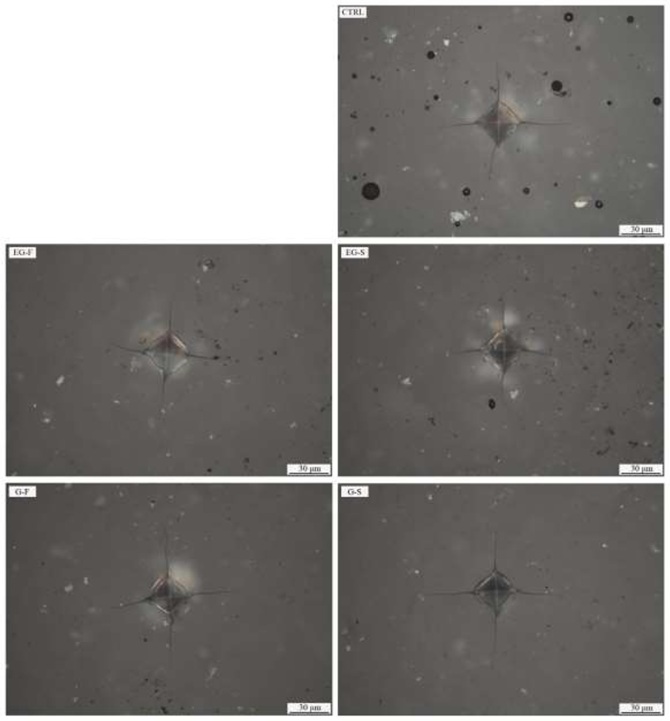
Acceptable pattern of well-developed cracks was obtained with Vickers indentations (4.9 N for 15 s), which revealed longer cracks after glaze than extended glaze and polishing (control).
The difference in crack length values between bilayer and monolithic discs were around 2 μm for all experimental groups. These differences led to similarly low residual stresses on the porcelain surface after all treatments.
The SEM analysis of the cracks revealed that most of the cracks in extended glazed samples (followed by slow or fast cooling) ended in clusters of crystals. On the other hand, cracks on glazed and polished surfaces ended in the glass matrix. Representative images of these observations are presented in Figures 5a–d.
Figure 5.

Crack tip patterns observed in EG and G groups. a) and b) depicts a G-F sample with crack ending in the glass phase. c) and d) show a EG-F sample with crack ending in a cluster of crystals.
4. Discussion
Extended glaze firing improved the resistance to crack initiation and propagation of the porcelain-veneered zirconia tested. However, no effect of the cooling protocol was observed, which made the first hypothesis to be accepted and the second one to be rejected. Accordingly, previous studies have also shown that long thermal treatments at temperatures above the Tg can improve flexural strength of porcelains and PVZs [35, 36]. Our results demonstrated that a 15 min dwell time is enough to improve the mechanical properties of these materials.
The XRD analysis showed one more peak of SiO2 in both extended glaze groups. This finding indicates some crystallization caused by the extended dwell time, which was confirmed by the surface SEM images (Fig. 2). Extended glaze groups also led to shorter crack lengths. Moreover, SEM images of the crack tips revealed that most cracks ended in clusters of crystals, suggesting a toughening mechanism. Interestingly, the control group (only polished) also presented one more peak of SiO2 and crack length similar to EG groups. Previous literature have reported that polishing feldspathic ceramics generates a compressive layer at the surface [50], which can also improve the resistance to crack propagation.
Previous studies have reported that glaze firings decrease flexural strength [50, 51] and increase the crack length of glass ceramics [33], mainly attributed to the removal of the surface compressive layer. Owing to the compressive stresses on the surface, our control group showed crack lengths of ~89 μm. Besides the healing of surface defects (suggested by decreasing Ra), glaze firing led to the dissolution of SiO2 in the glass matrix (XRD analysis) and removed the compressive layer (demonstrated by residual stresses analysis), which resulted in longer cracks (~100 μm). However, for our PVZ samples, it did not decrease flexural strength compared to the control group. On the other hand, despite also removing the compressive layer, extended glaze led to the precipitation of crystalline SiO2 and healing of deeper defects (suggested by the decrease in Ra and Rz), which resulted in a toughening mechanism and improved flexural strength. A sequence of studies by Aurélio and collaborators [33, 34, 52] found that a 15 min of dwell time for glazing monolithic hard machining glass ceramics improves strength, fatigue flexural strength, and toughness. Takahashi et al (2011) [53] described the crack healing mechanism in glass ceramics by the oxidation reaction of SiO2. According to them, if the crack healing material was crystal SiO2, the healed sample would exhibit higher bending strength, which is in agreement with our findings, since we observed one more crystalline peak and improved strength in extended glazed groups.
We also evaluated the resistance to crack propagation in monolithic porcelain discs, which showed results similar to the ones obtained with bilayer samples. By evaluating the crack length separately for stressed (bilayer) and non-stressed (monolith), we observed the effect of the microstructural changes on the crack propagation. Conversely, by comparing the crack length of each treatment in stressed and non-stresses samples, we could filter out the microstructural effect and focus on the influence of surface residual stresses on the crack propagation. As a result, the magnitude of stresses in all groups was similar, meaning that the crystalline phase formed did not significantly change the coefficient of thermal expansion [54] of the porcelain and the global residual stresses in the samples were the same after all treatments.
Although the statistical analysis showed that extended glaze led to a significant color difference, it was below the perceptibility threshold (ΔE00 < 0.8). [43] In addition, the translucency parameter was not affected by any of the treatments tested, which made the third hypothesis to be accepted. These findings are in agreement with the results of Aurélio and colleagues, [33] who also did not observe clinically perceptible alterations in the optical properties of a monolithic feldspathic ceramic after glaze and extended glaze. In addition, these findings confirm that the crystal phase formed during the extended firing has similar refractive index with the glass matrix, thus preserving the optical characteristics of the material.
The effect of cooling on mechanical properties of bilayer samples has been widely studied [34, 55–62]. Despite previous literature has reported improvement of mechanical properties of PVZ after slow cooling; a recent systematic review showed that the cooling effect can only be seen in complex geometries (eg. crowns) [63], which agrees with our results since we used flat samples. Moreover, it was previously demonstrated that less conservative slow cooling, like opening the furnace slightly below the Tg (eg., the fast cooling used in this study) is enough to decrease residual stresses [55] and improve the load to failure [62] of bilayer crowns.
The present findings indicate that extended glaze firing improves the resistance to crack initiation (flexural strength) and propagation of the tested porcelain-veneered zirconia system. Our analyzes showed that the dominant factor was the microstructural change after the extended dwell time, which led to a toughening mechanism (resistance to crack propagation) that, combined with the defects healing, resulted in strengthening the porcelain regardless of the cooling protocol chosen. Nevertheless, despite these promising results, we cannot ensure that there would be no interaction between cooling and dwell time on survival or load to failure of dental crowns. Extended glaze firing might be explored in future studies in crowns, since it can be a simple alternative for finishing porcelain-veneered zirconia restorations and improving its mechanical properties.
5. Conclusions
Extended glaze firing had a positive effect on the resistance to crack initiation and propagation of the porcelain-veneered zirconia system by smoothening of surface defects, crystallization of the glass matrix, and consequent toughening and strengthening of the porcelain overlay. Glaze and extended glaze did not lead to clinically perceptible alterations in color and translucency. In addition, no effect of the cooling protocols tested was observed in this study.
Highlights.
Extended glaze improves the resistance to crack initiation and propagation of PVZ
Glaze and extended glaze do not lead to perceptible changes in color and translucency
The effect of extended glaze had no interaction with the cooling protocol applied
Acknowledgements
The authors are thankful to the Federal Agency for Support and Evaluation of Graduate Education (CAPES) (finance code 001) and to Vita Zahnfabrik for the materials donation. This study was partially supported by the U.S. National Institute of Dental and Craniofacial Research (Grant Nos. R01DE026279 and R01DE026772).
Footnotes
Publisher's Disclaimer: This is a PDF file of an unedited manuscript that has been accepted for publication. As a service to our customers we are providing this early version of the manuscript. The manuscript will undergo copyediting, typesetting, and review of the resulting proof before it is published in its final form. Please note that during the production process errors may be discovered which could affect the content, and all legal disclaimers that apply to the journal pertain.
Declaration:
the authors declare that there is no conflict of interest regarding the publication of this article.
References
- [1].Larsson C, Wennerberg A. The clinical success of zirconia-based crowns: a systematic review. Int J Prosthodont. 2014;27:33–43. [DOI] [PubMed] [Google Scholar]
- [2].Manicone PF, Rossi Iommetti P, Raffaelli L. An overview of zirconia ceramics: basic properties and clinical applications. J Dent. 2007;35:819–26. [DOI] [PubMed] [Google Scholar]
- [3].Raigrodski AJ, Hillstead MB, Meng GK, Chung KH. Survival and complications of zirconia-based fixed dental prostheses: a systematic review. J Prosthet Dent. 2012;107:170–7. [DOI] [PubMed] [Google Scholar]
- [4].Ioannidis A, Bindl A. Clinical prospective evaluation of zirconia-based three-unit posterior fixed dental prostheses: Up-to ten-year results. J Dent. 2016;47:80–5. [DOI] [PubMed] [Google Scholar]
- [5].Sailer I, Feher A, Filser F, Gauckler LJ, Luthy H, Hammerle CH. Five-year clinical results of zirconia frameworks for posterior fixed partial dentures. Int J Prosthodont. 2007;20:383–8. [PubMed] [Google Scholar]
- [6].Sailer I, Zembic A, Jung RE, Siegenthaler D, Holderegger C, Hammerle CH. Randomized controlled clinical trial of customized zirconia and titanium implant abutments for canine and posterior single-tooth implant reconstructions: preliminary results at 1 year of function. Clin Oral Implants Res. 2009;20:219–25. [DOI] [PubMed] [Google Scholar]
- [7].Heintze SD, Rousson V. Survival of zirconia-and metal-supported fixed dental prostheses: a systematic review. Int J Prosthodont. 2010;23:493–502. [PubMed] [Google Scholar]
- [8].Rinke S, Kramer K, Burgers R, Roediger M. A practice-based clinical evaluation of the survival and success of metal-ceramic and zirconia molar crowns: 5-year results. J Oral Rehabil. 2016;43:136–44. [DOI] [PubMed] [Google Scholar]
- [9].Rinke S, Schafer S, Lange K, Gersdorff N, Roediger M. Practice-based clinical evaluation of metal-ceramic and zirconia molar crowns: 3-year results. J Oral Rehabil. 2013;40:228–37. [DOI] [PubMed] [Google Scholar]
- [10].Grohmann P, Bindl A, Hammerle C, Mehl A, Sailer I. Three-unit posterior zirconia-ceramic fixed dental prostheses (FDPs) veneered with layered and milled (CAD-on) veneering ceramics: 1-year follow-up of a randomized controlled clinical trial. Quintessence Int. 2015;46:871–80. [DOI] [PubMed] [Google Scholar]
- [11].Naenni N, Bindl A, Sax C, Hammerle C, Sailer I. A randomized controlled clinical trial of 3-unit posterior zirconia-ceramic fixed dental prostheses (FDP) with layered or pressed veneering ceramics: 3-year results. J Dent. 2015;43:1365–70. [DOI] [PubMed] [Google Scholar]
- [12].Nicolaisen MH, Bahrami G, Schropp L, Isidor F. Comparison of Metal-Ceramic and All-Ceramic Three-Unit Posterior Fixed Dental Prostheses: A 3-Year Randomized Clinical Trial. Int J Prosthodont. 2016;29:259–64. [DOI] [PubMed] [Google Scholar]
- [13].Passia N, Chaar MS, Kern M. Outcome of posterior fixed dental prostheses made from veneered zirconia over an observation period of up to 13 years. J Dent. 2019;86:126–9. [DOI] [PubMed] [Google Scholar]
- [14].Raigrodski AJ, Yu A, Chiche GJ, Hochstedler JL, Mancl LA, Mohamed SE. Clinical efficacy of veneered zirconium dioxide-based posterior partial fixed dental prostheses: five-year results. J Prosthet Dent. 2012;108:214–22. [DOI] [PubMed] [Google Scholar]
- [15].Benetti P, Pelogia F, Valandro LF, Bottino MA, Bona AD. The effect of porcelain thickness and surface liner application on the fracture behavior of a ceramic system. Dent Mater. 2011;27:948–53. [DOI] [PubMed] [Google Scholar]
- [16].Swain MV. Unstable cracking (chipping) of veneering porcelain on all-ceramic dental crowns and fixed partial dentures. Acta Biomater. 2009;5:1668–77. [DOI] [PubMed] [Google Scholar]
- [17].Bonfante EA, Rafferty B, Zavanelli RA, Silva NR, Rekow ED, Thompson VP, et al. Thermal/mechanical simulation and laboratory fatigue testing of an alternative yttria tetragonal zirconia polycrystal core-veneer all-ceramic layered crown design. Eur J Oral Sci. 2010;118:202–9. [DOI] [PubMed] [Google Scholar]
- [18].Kokubo Y, Tsumita M, Kano T, Fukushima S. The influence of zirconia coping designs on the fracture load of all-ceramic molar crowns. Dent Mater J. 2011;30:281–5. [DOI] [PubMed] [Google Scholar]
- [19].Shirakura A, Lee H, Geminiani A, Ercoli C, Feng C. The influence of veneering porcelain thickness of all-ceramic and metal ceramic crowns on failure resistance after cyclic loading. J Prosthet Dent. 2009;101:119–27. [DOI] [PubMed] [Google Scholar]
- [20].Quinn JB, Quinn GD, Sundar V. Fracture Toughness of Veneering Ceramics for Fused to Metal (PFM) and Zirconia Dental Restorative Materials. J Res Natl Inst Stand Technol. 2010;115:343–52. [DOI] [PMC free article] [PubMed] [Google Scholar]
- [21].Cheung KC, Darvell BW. Sintering of dental porcelain: effect of time and temperature on appearance and porosity. Dent Mater. 2002;18:163–73. [DOI] [PubMed] [Google Scholar]
- [22].Rekow ED, Silva NR, Coelho PG, Zhang Y, Guess P, Thompson VP. Performance of dental ceramics: challenges for improvements. J Dent Res. 2011;90:937–52. [DOI] [PMC free article] [PubMed] [Google Scholar]
- [23].Benetti P, Della Bona A, Kelly JR. Evaluation of thermal compatibility between core and veneer dental ceramics using shear bond strength test and contact angle measurement. Dent Mater. 2010;26:743–50. [DOI] [PubMed] [Google Scholar]
- [24].DeHoff PH, Barrett AA, Lee RB, Anusavice KJ. Thermal compatibility of dental ceramic systems using cylindrical and spherical geometries. Dent Mater. 2008;24:744–52. [DOI] [PMC free article] [PubMed] [Google Scholar]
- [25].Taskonak B, Mecholsky JJ Jr., Anusavice KJ. Residual stresses in bilayer dental ceramics. Biomaterials. 2005;26:3235–41. [DOI] [PubMed] [Google Scholar]
- [26].Guazzato M, Walton TR, Franklin W, Davis G, Bohl C, Klineberg I. Influence of thickness and cooling rate on development of spontaneous cracks in porcelain/zirconia structures. Aust Dent J. 2010;55:306–10. [DOI] [PubMed] [Google Scholar]
- [27].Tholey MJ, Swain MV, Thiel N. Thermal gradients and residual stresses in veneered Y-TZP frameworks. Dent Mater. 2011;27:1102–10. [DOI] [PubMed] [Google Scholar]
- [28].Fischer H, Hemelik M, Telle R, Marx R. Influence of annealing temperature on the strength of dental glass ceramic materials. Dent Mater. 2005;21:671–7. [DOI] [PubMed] [Google Scholar]
- [29].Callister WDJR, G. D Materials Science and Engeneering an Introduction. 8th ed: John Wiley & Sons; 2013. [Google Scholar]
- [30].Preston F The fundamental law of annealing. Trans Opt Soc. 1925;26:270–3. [Google Scholar]
- [31].Addison O, Cao X, Sunnar P, Fleming GJ. Machining variability impacts on the strength of a ‘chair-side’ CAD-CAM ceramic. Dent Mater. 2012;28:880–7. [DOI] [PubMed] [Google Scholar]
- [32].Ahmad R, Morgano SM, Wu BM, Giordano RA. An evaluation of the effects of handpiece speed, abrasive characteristics, and polishing load on the flexural strength of polished ceramics. J Prosthet Dent. 2005;94:421–9. [DOI] [PubMed] [Google Scholar]
- [33].Aurelio IL, Dorneles LS, May LG. Extended glaze firing on ceramics for hard machining: Crack healing, residual stresses, optical and microstructural aspects. Dent Mater. 2017;33:226–40. [DOI] [PubMed] [Google Scholar]
- [34].Aurelio IL, Fraga S, Dorneles LS, Bottino MA, May LG. Extended glaze firing improves flexural strength of a glass ceramic. Dent Mater. 2015;31:e316–24. [DOI] [PubMed] [Google Scholar]
- [35].Denry IL, Holloway JA, Tarr LA. Effect of heat treatment on microcrack healing behavior of a machinable dental ceramic. J Biomed Mater Res. 1999;48:791–6. [DOI] [PubMed] [Google Scholar]
- [36].Taskonak B, Borges GA, Mecholsky JJ Jr., Anusavice KJ, Moore BK, Yan J. The effects of viscoelastic parameters on residual stress development in a zirconia/glass bilayer dental ceramic. Dent Mater. 2008;24:1149–55. [DOI] [PubMed] [Google Scholar]
- [37].de Jager N, Feilzer AJ, Davidson CL. The influence of surface roughness on porcelain strength. Dent Mater. 2000;16:381–8. [DOI] [PubMed] [Google Scholar]
- [38].Dong JK, Luthy H, Wohlwend A, Scharer P. Heat-pressed ceramics: technology and strength. Int J Prosthodont. 1992;5:9–16. [PubMed] [Google Scholar]
- [39].Fairhurst CW, Lockwood PE, Ringle RD, Thompson WO. The effect of glaze on porcelain strength. Dent Mater. 1992;8:203–7. [DOI] [PubMed] [Google Scholar]
- [40].Ozturk O, Uludag B, Usumez A, Sahin V, Celik G. The effect of ceramic thickness and number of firings on the color of two all-ceramic systems. J Prosthet Dent. 2008;100:99–106. [DOI] [PubMed] [Google Scholar]
- [41].Pires-de-Souza Fde C, Casemiro LA, Garcia Lda F, Cruvinel DR. Color stability of dental ceramics submitted to artificial accelerated aging after repeated firings. J Prosthet Dent. 2009;101:13–8. [DOI] [PubMed] [Google Scholar]
- [42].Nogueira AD, Della Bona A. The effect of a coupling medium on color and translucency of CAD-CAM ceramics. J Dent. 2013;41 Suppl 3:e18–23. [DOI] [PubMed] [Google Scholar]
- [43].Paravina RD, Ghinea R, Herrera LJ, Bona AD, Igiel C, Linninger M, et al. Color difference thresholds in dentistry. J Esthet Restor Dent. 2015;27 Suppl 1:S1–9. [DOI] [PubMed] [Google Scholar]
- [44].Salas M, Lucena C, Herrera LJ, Yebra A, Della Bona A, Perez MM. Translucency thresholds for dental materials. Dent Mater. 2018;34:1168–74. [DOI] [PubMed] [Google Scholar]
- [45].Standardization IOf. 4287 ISO. Geometrical product specifications (GPS) - surface texture: profile method, terms definitions and surface texture parameters Geneva1997.
- [46].Standardization IOf. 6872 ISO. Dentistry – ceramic materials Geneva: 2015. [Google Scholar]
- [47].Wachtman JB, Capps W, Mandel J. Biaxial Flexure Tests of Ceramic Substrates. J Mater. 1972;7:188-&. [Google Scholar]
- [48].Zeng K, Oden A, Rowcliffe D. Evaluation of mechanical properties of dental ceramic core materials in combination with porcelains. Int J Prosthodont. 1998;11:183–9. [PubMed] [Google Scholar]
- [49].Zeng KY, Rowcliffe D. Experimental-Measurement of Residual-Stress Field around a Sharp Indentation in Class. J Am Ceram Soc. 1994;77:524–30. [Google Scholar]
- [50].Giordano R Materials for chairside CAD/CAM-produced restorations. J Am Dent Assoc. 2006;137:14s–21s. [DOI] [PubMed] [Google Scholar]
- [51].Fraga S, Valandro LF, Bottino MA, May LG. Hard machining, glaze firing and hydrofluoric acid etching: Do these procedures affect the flexural strength of a leucite glass-ceramic? Dent Mater. 2015;31:e131–40. [DOI] [PubMed] [Google Scholar]
- [52].Aurelio IL, Prochnow C, Guilardi LF, Ramos GF, Bottino MA, May LG. The effect of extended glaze firing on the flexural fatigue strength of hard-machined ceramics. J Prosthet Dent. 2018;120:755–61. [DOI] [PubMed] [Google Scholar]
- [53].Takahashi K, Ando K, Nakao W. Crack-Healing Ability of Structural Ceramics and Methodology to Guarantee the Reliability of Ceramic Components. Advances in Ceramics - Characterization, Raw Materials, Processing, Properties, Degradation and Healing. 2011:351–70. [Google Scholar]
- [54].Kim J, Dhital S, Zhivago P, Kaizer MR, Zhang Y. Viscoelastic finite element analysis of residual stresses in porcelain-veneered zirconia dental crowns. J Mech Behav Biomed Mater. 2018;82:202–9. [DOI] [PMC free article] [PubMed] [Google Scholar]
- [55].Benetti P, Kelly JR, Sanchez M, Della Bona A. Influence of thermal gradients on stress state of veneered restorations. Dent Mater. 2014;30:554–63. [DOI] [PubMed] [Google Scholar]
- [56].Paula VG, Lorenzoni FC, Bonfante EA, Silva NR, Thompson VP, Bonfante G. Slow cooling protocol improves fatigue life of zirconia crowns. Dent Mater. 2015;31:77–87. [DOI] [PubMed] [Google Scholar]
- [57].Tanaka CB, Ahmad NHB, Ellakwa A, Kruzic JJ. Effect of cooling protocol on mechanical properties and microstructure of dental veneering ceramics. Dent Mater. 2019;35:1498–505. [DOI] [PubMed] [Google Scholar]
- [58].Tanaka CB, Ballester RY, De Souza GM, Zhang Y, Meira JBC. Influence of residual thermal stresses on the edge chipping resistance of PFM and veneered zirconia structures: Experimental and FEA study. Dent Mater. 2019;35:344–55. [DOI] [PMC free article] [PubMed] [Google Scholar]
- [59].Tanaka CB, Harisha H, Baldassarri M, Wolff MS, Tong H, Meira JB, et al. Experimental and finite element study of residual thermal stresses in veneered Y-TZP structures. Ceram Int. 2016;42:9214–21. [DOI] [PMC free article] [PubMed] [Google Scholar]
- [60].Wendler M, Belli R, Petschelt A, Lohbauer U. Characterization of residual stresses in zirconia veneered bilayers assessed via sharp and blunt indentation. Dent Mater. 2015;31:948–57. [DOI] [PubMed] [Google Scholar]
- [61].Wendler M, Belli R, Petschelt A, Lohbauer U. Spatial distribution of residual stresses in glass-ZrO2 sphero-cylindrical bilayers. J Mech Behav Biomed Mater. 2016;60:535–46. [DOI] [PubMed] [Google Scholar]
- [62].Tang YL, Kim JH, Shim JS, Kim S. The effect of different cooling rates and coping thicknesses on the failure load of zirconia-ceramic crowns after fatigue loading. J Adv Prosthodont. 2017;9:152–8. [DOI] [PMC free article] [PubMed] [Google Scholar]
- [63].Rodrigues CDS, Aurelio IL, Kaizer MDR, Zhang Y, May LG. Do thermal treatments affect the mechanical behavior of porcelain-veneered zirconia? A systematic review and meta-analysis. Dent Mater. 2019;35:807–17. [DOI] [PMC free article] [PubMed] [Google Scholar]