Abstract
The effect of indoor airflow has been confirmed on the diffusion and transmission of droplets generated when talking or sneezing by a person with a viral respiratory infection such as COVID-19. The present study to investigate the effect of airflow in an indoor environment (a classroom) on the distribution and transmission of droplets emitted from speaking and cough by an infected person. A numerical analysis to investigate the persistence and deposition of particles on the surfaces of desks and the faces of residents (teacher and students) under various scenarios, including the opening of windows. This study puts forward two types of conditions while the teacher is speaking and the cough of some students for the distribution of pathogenic particles. Computational Fluid Dynamics used to conduct the study, using the Euler-Lagrange approach to capture the transport of the particles, and the RANS equations to compute the airflow field in the classroom. The results indicate the significant effect of air conditioning and open window close to the infected person in reducing environmental pathogens. Moreover, the concentrations of virus particles increase greatly near the output; hence, the presence of people in these areas increases the risk of contracting the disease. Furthermore, when all the windows are closed, due to the low output capacity, the particles spread in all areas of the domain and increase the risk of infection. Therefore, it is recommended that the window be open in indoors environment especially the window next to the speaker.
Keywords: CFD, Classroom, Deposition, Eulerian-Lagrangian model, SARS-CoV-2
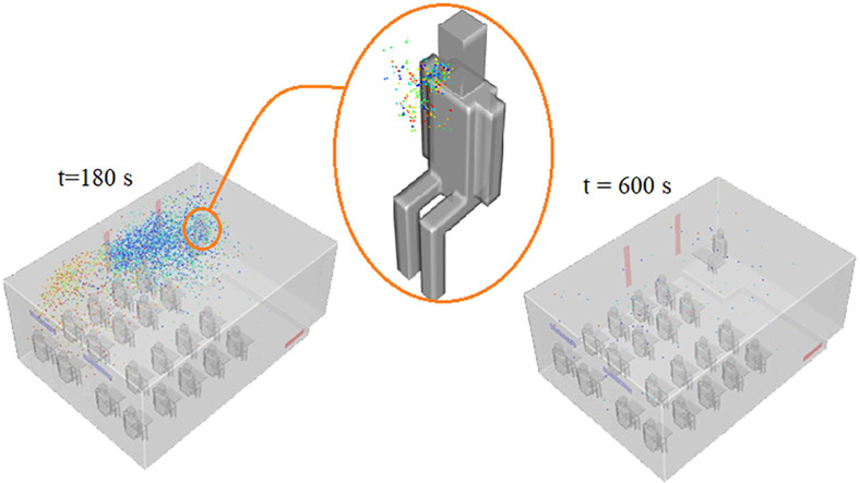
Graphical abstract
Nomenclature
- CFD
Computational fluid dynamic
- DPM
Discrete phase model
- DRWM
Discrete random walk model
- LES
Large eddy simulation
- RANS
Reynolds-averaged Navier-stokes
- RH
Relative humidity
- S
Student
- Vent
Ventilation
- Win
Window
- Latin
letters
Particle mass
Volume
Particle volume
Fluid velocity
Particle velocity
Fluctuating eddy velocity
Pressure
Fluid location
Particle location
Force on the particle
Drag force
Gravitational force
Additional force
Saffman force
Pressure gradient force
Particle diameter
Drag coefficient
Particle Reynold's number
Gravitational acceleration
- sgn
Sign function
- Greek
letters
Turbulence dissipation rate
Volumetric fraction of particles
Fluid shear stress
Fluid density
Particle density
Dynamic viscosity of fluid
Normal random number
1. Introduction
Once again, a severe respiratory infectious disease called COVID-19 caused by acute respiratory syndrome (SARS-CoV-2) has affected the health, economy, and security of human societies in the 21st century. COVID-19 is a disease that has affected out lives in almost the past year, mainly in-group activities. One example is education, from elementary school to college. Ensure safe conditions for students and professors is vital to resume activities in the classrooms. A viral disease is more prevalent than the previous common diseases of the century, such as SARS in 2003, and the Middle East respiratory syndrome coronavirus (MERS-CoV) in 2013, and has affected all countries (Shi et al., 2020). Its common symptoms include fever, cough, myalgia, and fatigue (Zu et al., 2020). According to the World Health Organization, more than ninety million people worldwide have been infected with the disease and about two million have died. The disease was first reported in Wuhan, China (Zhu et al., 2020). Its rate of transmission is much higher in indoor and enclosed environments than in outdoor environments. In general, the risk of transmission of respiratory diseases in indoor environments is affected by the following four factors: 1) virus particle size characteristics, 2) airflow pattern, 3) virus type, and 4) specific characteristics of the host (Kohanski et al., 2020). Several physical factors play an important role in airborne transmission. These can be divided in (a) the geometry of the classroom and its boundary conditions, and (b) source of the particles and its location in the space. According to researches, the virus (SARS-CoV-2) is transmitted from an infected person to a healthy person in two direct ways, (a) directly: including respiratory activities of the infected person such as breathing, talking, sneezing, and coughing, (b) indirect: contact with surfaces and equipment infected with the virus (Jayaweera et al., 2020). Understanding and recognizing respiratory droplets sizes and their dispersion is essential for assess the mechanisms and control of disease transmission through droplet-borne and airborne routes (Liu et al., 2017). The behavior of particles resulting from these respiratory activities in the environment depends on their sizes, some of which are larger (>5 μm) and are called droplets, and most of them deposited by their gravity before they have a chance to evaporate. Some other smaller particles (<5 μm), called aerosols, evaporate rapidly as they enter the environment and remain suspended in the air. Furthermore, these aerosol particles are most likely to contaminate healthy people indoors because larger droplets are trapped in the upper airways but these tiny particles enter the lower respiratory tract through inhalation and lead to lung infections. The particle sizes generated from breathing, coughing, sneezing and talking showed healthy individuals generate particles between 0.01 and 500 mm, and individuals with infections produce particles between 0.05 and 500 mm (Gralton et al., 2011). It is known; these suspended particles are transported with the airflow in the indoor environment such as classrooms, public transportation, buildings, gyms, so on (specifically in low ventilation environments), and are the most prevalent cause of people suffering from these particles (Buonanno et al., 2020). As a result, predicting the release and distribution of droplets from the affected person's respiratory activities indoors can play an important role in reducing and breaking the chain of the disease.
The mortality rate of this disease is estimated between 2% and 3% and most of these statistics are related to the elderly and those with underlying diseases (Bhattacharyya et al., 2020). New mutations in the virus (SARS-CoV-2) and its unknown features have become a global concern; hence, different countries have adopted policies to confront this invisible enemy such as quarantining cities, controlling the movement of people, preventing large gatherings, wearing masks in different places, heavy fines for violators, and reducing the capacity of public transportation systems. A social distance of 1.5–2 m is a policy adopted by the World Health Organization to control the progression and epidemic of this disease. This recommendation is regardless of considering the effects of relative humidity and ambient temperature (Diwan et al., 2020). However, numerical and experimental modeling has indicated that virus particles during coughing and sneezing can travel a distance of 7–8 m in real conditions (Bourouiba, 2020). The use of facemasks and observance of distance has been one of the first preventive measures recommended by the World Health Organization and governments (Chan, 2020). Wears the facemask, serves primarily a dual preventive purpose to protecting oneself from getting viral infection and protecting others. Therefore, if everyone wears a facemask in public, especially indoors with poor ventilation, it offers a double barrier against COVID-19 transmission (Abboah-Offei et al., 2021). However, some research suggests that aerosols pass through high performance filters (Leung et al., 2020). Therefore, it is important to study the movement and transmission of pathogens resulting from respiratory activities indoors and in spaces with mechanical ventilation such as medical centers, educational centers, and public transportation systems to improve air distribution and reduce the risk of infection in healthy people.
Several studies conducted on the dissemination of pathogenic particles indoors under different conditions and examined appropriate strategies to minimize transmission of the virus from infected people to others, reduce the shelf life of particles in the environment, and improve flow patterns. For instance (Bhattacharyya et al., 2020), examined the airflow pattern and the effectiveness of mixing air conditioning with disinfectant aerosol particles to kill COVID-19 in an isolated room. In their study, they found that turbulence in the room could be an efficient way to disperse disinfectant particles in more space of the room and it directly related to the loss of coronavirus-carrying particles. In another study (Liu et al., 2020), examined the temporal-spatial characteristics of bio-aerosol particle dispersion and their deposited in a bio-laboratory level 3 and concluded that the concentrations of the particles after injection into the environment reached a steady state after 400 s. They also stated that about 70% of all biological aerosol particles settle on surfaces, equipment, and walls. As well (Jankovic, 2020) modeled the movement of particles inside the building and concluded that small pathogenic particles (aerosols) remain suspended in the air for a long time due to their lower mass and the presence of turbulent flow can help particles remain in the room air. He also found that one-way airflow was effective in purifying the room of pathogenic particles. In a study by (Hang et al., 2015), they examined the effect of opening and closing time between a room contaminated with pathogens and a clean room in the transmission of infectious particles in the air. They concluded that the difference in temperature and the existing concentration gradient caused a two-way buoyant flow of the stimulus and the transfer of polluted air through the doors. They found that the longer the door was open or the lower the rate of air change, the more pathogens transferred to a clean room, thereby increasing the time required to remove the particles. Furtheremore, (Zhang et al., 2019) numerically and experimentally investigated the distribution of aerosol particles in a room with air conditioning. In their model, they used both displacement and mixing ventilation systems. Their results indicated that in the presence of displacement ventilation, the temperature, and relative humidity of the source air had less effect on the number of airborne particles and the number of particles leaving the room compared to the ventilation rate and airflow distribution patterns. They also concluded that displacement ventilation (DV) has a significant effect on minimizing the disease risk in comparison with mixed ventilation. Another air-borne transmission study for optimization an air distribution of a general three-bed hospital ward by changing the position of inputs and outputs carried out by (Wang et al., 2021). They evaluated two parameters, total maximum time (TMT) and overall particle concentration (OPC), to reflect the particle mobility and probability to cause cross-infection respectively. Results show that a bottom-in and top-out air distribution proposal is recommended to minimize the cross-infection.
The use of models based on computational fluid dynamics (CFD) is a well-known way to study and model airflow and performance of indoor ventilation systems. Many researchers have used this model for example: (Borro et al., 2021) modeled the role of HVAC systems in the diffusion of the contagion through CFD simulations of cough at the waiting room. The results show that HVAC airflow remarkably enhances infected droplets diffusion in the indoor environment within 25 s from the cough event, despite the observed dilution of saliva particles containing the virus. Moreover (Jacob et al., 2019) to optimize the ventilation strategy towards contaminant suppression in the isolation room and model for various orientation of air supply and exhaust vents of the isolated room was developed, and simulation was carried out using in-house CFD solver. They suggest that immune-suppressed patients should be kept near the air supply and infectious patients near the exhaust. This model is a very powerful and efficient tool for investigating fluid flow indoor such as chasing scattered particles during breathing, talking, coughing, and sneezing in which many parameters are involved. Since medical treatments have side effects and do not provide complete safety, it seems logical to examine ways to clear contaminated environments and minimize the spread of the COVID-19 in educational centers in addition to taking preventive and supportive measures. This is essential to protect the teachers, students, staff, and families. However, there is no study in this field.
The present study examined the distribution of new coronavirus particles while a teacher spoke in a 7 m × 5 m × 3 m (length, width, height) classroom by considering twenty students (the height is 1.73 m) under the influence of flow patterns created by the displacement ventilation system (mechanical and natural ventilation). For different scenarios such as opening different classroom windows and changing the injection position, and studied coughing by several students in some sensitive and important states in the classroom, and then determined the safe and dangerous zones inside the classroom. Furthermore, we considered teacher's desk (1 m × 0.5 m × 0.01 m) and students' desk (0.5 m × 0.3 m × 0.01 m) to obtain the fraction of particles deposited on them. We assumed it would take 11 min to clean the classroom air (Hedrick et al., 2013).
In the present study, we considered the diffusion and motion of particles in the environment as a three-dimensional, transient, and turbulent model. Given that the Euler-Lagrange approach covers a wide range of particle sizes in both dense and dilute flows and considers nonlinear interactions and unbalanced effects in problem solving, it is an appropriate and logical method to describe multiphase flows (Shankar Subramaniam, 2012). The properties and content of exhaled particles from airway reopening mechanism suggests a noninvasive manner to obtain samples from the respiratory tract lining fluid of small airways (Bake et al., 2019). Therefore, we used the Euler-Lagrange method to describe the gas-liquid phase flow. The gas-phase (continuous flow phase) consisted of two components, air, and water vapor, and we modeled the phase from Euler's point of view. On the contrary, used the Lagrange's approach based on the discrete phase model for the liquid phase (injected water particles and droplets). We utilized the Reynolds-averaged Navier-Stokes equations (RANS) to calculate the fluid velocity field according to certain boundary conditions. Furthermore, we used the standard k-ε turbulence model for fluid flow and utilized the model based on the discrete stochastic method to contribute the turbulent particle dispersion from the Lagrange's perspective (Jin et al., 2015). Prediction of extra thoracic aerosol deposition using RANS-Random Walk and LES approaches studied by (Dehbi, 2011). The effect of the dispersion model on the particle motion, as well as the order of coupling between the continuous carrier phase and the dispersed phase, is investigated to assessment of particle-tracking models for dispersed particle-laden flows (Greifzu et al., 2016). They state the results for the dispersed solid phase are revealed a good accordance between the simulation results and the experiments. The research results can be used to help build new learning environments and break the chain of disease outbreak.
2. The equations and methods
2.1. Equations
In order to investigate dispersed flow of inert particles, the large eddy simulation (LES) turbulence model of the conservation equations is used. For the carrier bulk multiphase flow, the mathematical formulations include a continuous and discrete phase. For the incompressible, turbulent flow, which is the continuous carrier phase, the mass and momentum transport in the fluid phase described by the RANS equations as follows:
Continuous phase: It includes airflow in which the equations are tensor based on Euler's view as follows:
| (1) |
| (2) |
Where and are the Reynolds-averaged flow velocity and pressure respectively, is the fluid density and is used to denote other forces, such as gravity, which are acting on the fluid. The Reynolds stresses is modeled by employing an eddy-viscosity approach,
| (3) |
| (4) |
Here, defined as a rate of strain tensor for the resolved scale. We employed the k-ε turbulence model in the current work. The equations for the calculation of turbulent kinetic energy and dissipation rate in an inertial frame are as follows:
For turbulent kinetic energy k,
| (5) |
And for dissipation rate ε,
| (6) |
, represents the turbulence eddy viscosity:
| (7) |
Where, constants. These constants are
Discrete phase: This phase consists of suspended particles that studied from the Lagrange's point of view.
| (8) |
The momentum equation for particles is derived from the balance between inertial forces and external forces applied to the particle.
| (9) |
Where, is the particle position vector, Particle velocity, Particle mass, and the result is the forces applied on the particle as calculated below.
| (10) |
Where, drag force, Gravity force, and Other additional forces applied on the particle, including the Saffman lift force, the pressure gradient, the mass added, the clamping, the protruding, the thermophoresis, and the Magnus. Since the particles are small, enough and we do not have severe temperature changes, we consider only pressure gradient force furthermore; the Saffman lift force may be relatively large near a classroom's wall for fine indoor particles (Mahdavimanesh et al., 2013). The Stokes-Cunningham drag model was used to examine the influence of the drag force in the present model. As a result, the total force on the particle is as follows.
| (11) |
where, Saffman lift force, the force caused by the pressure gradient, and is the gravity force.
| (12) |
| (13) |
is the drag coefficient and depends on the Reynolds number of the particle.
| (14) |
| (15) |
is the fluid dynamic viscosity coefficient.
| (16) |
| (17) |
| (18) |
In this phase, the Discrete Random Walk Model (DRWM) is used to model the turbulent dispersion of contaminants by adding an eddy fluctuating component to the mean air velocity. The local air velocity is:
| (19) |
| (20) |
where is the mean air velocity, is the fluctuating eddy velocity and is a normal random number which accounts the randomness of turbulence by a mean value. In this model, the fluctuating eddy velocity is varying by the length and the lifetime of the eddy as expressed in Equations (21), (22)).
| (21) |
| (22) |
2.2. Geometry and boundary conditions
Fig. 1 shows a schematic and mesh of a classroom with a teacher and twenty students by taking into account the desks. In addition, Fig. 2 illustrates dimensions of the classroom and the position of the inputs and outputs of the airflow and equalizer (0.8 m × 0.2 m). For a more detailed examination of the results, all individuals and desks defined separately and distinctly from each other.
Fig. 1.
Classroom schematic and hexa-unstructured computational grid, (a) Perspective view and introduction of different parts; (b) Naming and arranging students; (c) grid of plane ZY; (d) grid of plane XZ and refined grid around teacher.
Fig. 2.
Dimensions of the classroom and the position of the: (a) inputs and (b) outputs of the airflow.
Considering the comfort conditions in the classroom and the importance of air conditioning in reducing air pollution, we considered the ventilation rate of 340 CFM (Hedrick et al., 2013). We used the non-slip and trap boundary condition for all surfaces, including walls, as well as students, teachers, and desks. Moreover, boundary conditions in inlets include velocity inlet () with relative humidity, 50% and turbulent intensity equal 10% (with turbulent length scale = 0.02 m). At the outlets, pressure outlet and escape boundary condition is set.
We used the CFD model to simulate the transfer and dissemination of spherical particles while speaking and coughing in the classroom. In the present study, we modeled the mouth of the person injecting the particles in a circle with a diameter of 0.03 m. Since small particles have less inertia and they evaporate immediately after leaving the mouth and remain suspended in the air, the aerosol particles are the most common causes of contamination of healthy people indoors (Gralton et al., 2011), hence, we mainly focused on smaller particles. The particle discharge velocity in speaking was equal to 3 m/s and the total number of particles was estimated at 36000 (all of them are assumed to be contaminated particles) (Asadi et al., 2019). According to studies on cough, the particle diameters selected based on the Weibull distribution function (Fig. 3 ). (Diwan et al., 2020) have extend the droplet sizes dispersed in typical coughing/sneezing to include three classes of droplets: (a) very small droplets (<10 μm) that follow fluid streamlines; (b) moderate-sized droplets (10–100 μm)for which droplet inertia and gravitational settling are both relevant; and (c) large droplets (>100 μm) which settle under gravity. Table 1 . Represents the number and diameters of particles in coughing (Yan et al., 2020). Table 2 . Presents the particle diameter distribution with injection details for speaking and coughing states (Gupta et al., 2009).
Fig. 3.
Distribution of particle diameter in coughing state.
Table 1.
Particle size and number distribution for cough state.
| Diameter (μm) | 1 | 2 | 5 | 8 | 10 | 15 | 20 | 30 | 40 | 50 |
|---|---|---|---|---|---|---|---|---|---|---|
| Number | 20 | 40 | 120 | 500 | 600 | 1000 | 450 | 150 | 70 | 50 |
Table 2.
Details of DPM for water liquid particle.
| Particle component | Water liquid |
|---|---|
| Density Specific heat capacity |
998.2 4.182 kJ/kg K |
| Drag law | Stokes-Cunningham |
| Turbulent dispersion |
|
| Injection1 | Particle sizes: Injection velocity: 3 m/s Injection type: cone Injection angle: 30 |
| Injection2 | Particle sizes: Injection velocity: 11.2 m/s Injection type: cone Injection angle: 40 |
Injection1: For speaking mode & Injection2: For coughing mode.
2.3. Definition of states and solution scenarios
In the present study, the windows were not wide open (20% of the total surface of the windows open) to limit the output flow range (and reducing costs due to running conditioning systems) and also increase the flow rate in exiting (except for scenarios 11 and 12). This view also prevented cold air from entering the classroom during the cold seasons.
2.3.1. State A) speaking
In this state, we assumed that the teacher was the injector of the contaminated particles in the environment so that the teacher spoke continuously for 2 min and spread the particles in the environment. Then, we tracked the particles at the next 8 min (the total particle tracking time from the injection time was 10 min) and we examined the results for the 12 scenarios in Table 3 .
Table 3.
Introducing scenarios.
| Scenario no. | Definetion |
|---|---|
| 1 | All windows is closed |
| 2 | Only window 1 is open |
| 3 | Only window 2 is open |
| 4 | Only window 3 is open |
| 5 | windows 1 and 2 is open |
| 6 | windows 1 and 3 is open |
| 7 | windows 2 and 3 is open |
| 8 | All windows is open |
| 9 | All windows is open and teacher is standed |
| 10 | All windows is open and teacher is standed in location (0, 0.3, 0.5) |
| a | only natural ventilation (the door is fully open and without mechanical ventilation) |
| b | only natural ventilation (the door is fully open and without mechanical ventilation) |
This scenario is checked for 10 min.
This scenario is the same as scenario 11 for twice the duration.
In scenarios 11 and 12, it is assumed that the classroom air conditioning, unlike the first 10 scenarios, was done only through natural airflow. In other words, electrical ventilation systems were eliminated in the scenarios (this assumption is reasonable in case of a power outage). In the scenarios, a class with dimensions of 2.1 m × 1 m was a speed input of 0.1 m/s with an angle of - 45° (in the direction of the axis x). To provide thermal comfort for those present in the classroom during the scenarios, we assumed that the windows were at their maximum opening dimensions (1.5 m × 0.3 m).
2.3.2. State B) cough
In this state, we examined the students' cough for six different sources in the first eight scenarios of Table 3.
2.4. Numerical model
2.4.1. Simulation
We used ANSYS FLUENT-19 to simulate the present problem and the hexa-unstructured mesh created by ICEM CFD. The SIMPLE algorithm has be used to coupling between pressure and velocity field. The minimum remaining convergence scale was from the order of in solving the flow field, and for momentum equations and turbulence model. In the present study, we first resolved the fluid field, and then injected the particles by keeping the continuous flow solution constant, and performed simulation for 10 min to investigate the particle motion in the first state (speaking). Determining the volume fraction of the particles (), we found that as , the flow was dilute hence (Elghobashi, 1994), we utilized a one-way coupling to create coupling between the continuous and particle phases.
2.4.2. Validation
In the present section, we compared the simulation results with research by (Shao et al., 2021) for validation. According to the conditions of the research, we separately examined the independence of results of the computational grid and the time step as presented in the following table.
2.4.3. Grid independence
Considering the importance and effect of grid type and density on flow field simulation results (Srebric et al., 2008), we used a regular and organized grid in the Cartesian coordinate system to study and analyze the fluid flow field in the classroom. Large grids increase the resolution error and distort the results from the real state. On the contrary, very small grids also increase the resolution time, but we did not consider such small grids. To investigate this issue, we performed a grid independence test and presented the results in Table 4 . In the test, we measured the magnitude of the average velocity and the average static pressure per grids in sizes of 100 mm, 80 mm, 60 mm, 50 mm, and 40 mm on a line with coordinates of (0,1,-2) and (0,1,3) (Table 4). The results indicated that increasing the number of grid elements from 2163831 to 3561554 did not significantly change the flow field. Therefore, the grid size of 50 mm was logical for the study.
Table 4.
Grid-independency study results.
| Element size (cm) | Number of elements | Average static pressure (Pa) | Average velocity magnitude (m/s) |
|---|---|---|---|
| 10 | 1058718 | 0.0214 | 0.0402 |
| 8 | 1384153 | 0.0223 | 0.0416 |
| 6 | 1803970 | 0.0220 | 0.0461 |
| 5 | 2163831 | 0.0225 | 0.0467 |
| 4 | 3561554 | 0.0227 | 0.0469 |
2.4.4. Independence of time step
To test the time step independence, we resolved the problem for time steps of 0.02s, 0.1s, and 0.2s, and then determined the fraction of particles deposited on different surfaces. Fig. 4 shows the results. As shown, the slope of changes between the time steps of 0.02 and 0.1 was lower; hence, we used a time step of 0.1 to simulate particle dispersion with sufficient accuracy in the transient state.
Fig. 4.
Time independency results.
3. Results
Given that the facial surfaces and desks were among the sensitive points and the probability of catching the disease was higher through particles attached to the surfaces, we focused more on the surfaces in the “results” section to evaluate the results of problem solving in both A and B states in the present study. In addition to the surfaces, we discussed the issues such as airborne particles, exit from the class, and deposited on the body.
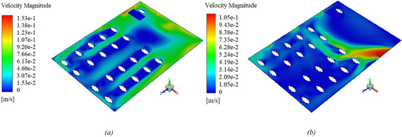
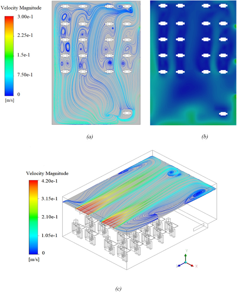
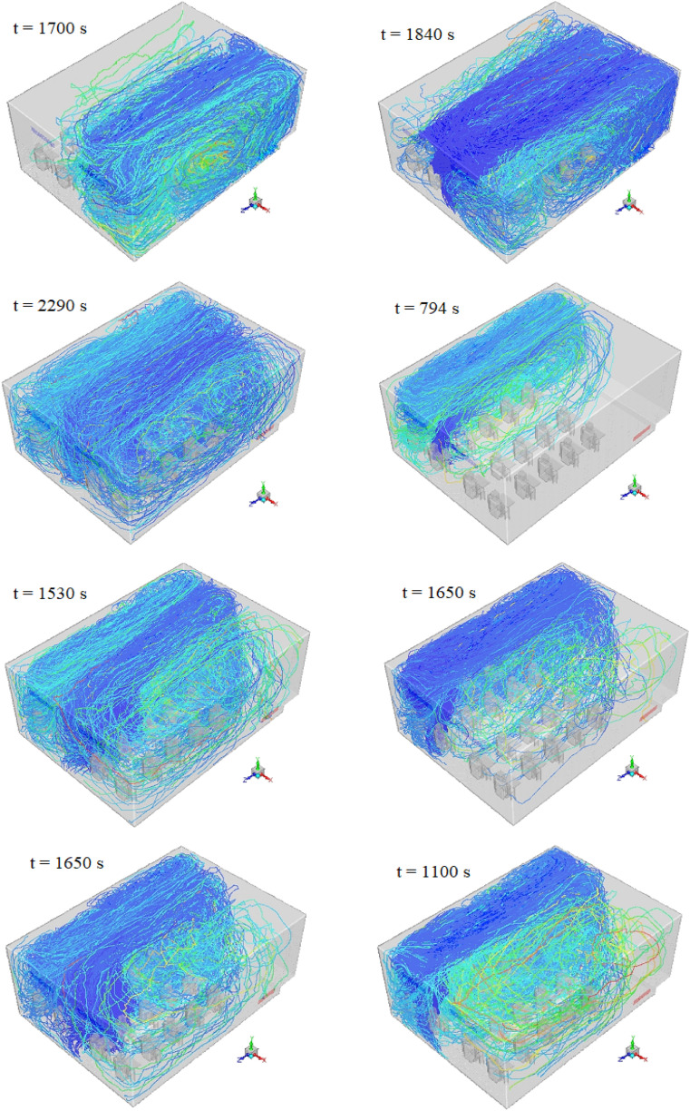
The following figures show the velocity field distribution for several different scenarios (Fig. 5, Fig. 6 ). Observing Fig. 6, we notice the formation of flow vortices and recirculation zone. These vortices are affected by the placement of people, objects, and geometry in the classroom, and by trapping the virus, cause the virus particles to remain in the environment for a long time, as result increasing the risk of infection.
Fig. 5.
Velocity distribution on the plane of Y = 1 m, (a) for Scenario 4, and (b) for Scenario 11.
Fig. 6.
Velocity distribution for Scenario 9, (a) velocity streamline and (b) velocity contour on the plane of XZ in location Y = 1.1 m; (c) Velocity streamline distribution on the plane of Y = 2.6 m (isometric view).
Comparing the velocity distributions presented in Fig. 5 (a) with (b), we conclude that the airflow inside the class is highly dependent on the inlet location of the flow. As shown in Fig. 5 (a), 6 the flow of the inputs collides with the opposite wall in a straight path, and then the flow streamlines are distributed in different directions of the class. However, in the last two scenarios, the input flow from the door is such that it is mostly scattered in the front of the classroom and often affects the people in the front (Fig. 5 (b)).
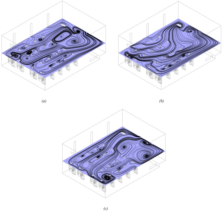
As mentioned above, the formation of flow vortices has a significant effect on the shelf life of the particles inside the domain. To find out this, Fig. 7 provides a comparison between streamlines and recirculation zone during scenarios 1, 5, and 7. As shown in this figure, in all three scenarios a strong recirculation zone is formed at the end of the classroom (near the corner), with the difference that with the closing of all windows (scenario 1), that from the left area, in figures (a) and (b), to moved right. Another noteworthy point is the formation of relatively strong recirculation zone near the outlets. In addition, by comparing the two figures (a) and (b), we find that closing the front window (window 1) and opening the end window (window 3) reduces the amount of recirculation zone.
Fig. 7.
Comparison of the velocity streamlines and recirculation zone on plane Y = 1.25 m (isometric view) for different scenarios, (a) 5, (b) 7, and (c) 1.
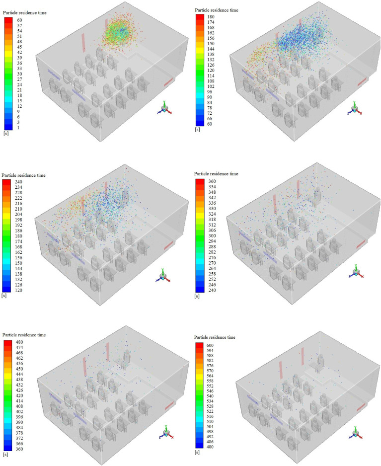
Fig. 8. Illustrated the aerosol cloud profiles at six instances of time (60–600 s) inside the domain for scenario 5. This shows a comparison of how aerosol clouds are distributed and transmitted inside the cabin during the different times. As can be seen in first 60 s most of the particles move upwards and surround the teacher after leaving the teacher's mouth, and most of them accumulate above the teacher's heads. Then, with the over the time and with the equilibrium of the solution, the particles move with the airflow towards the outlets and lead to the dispersion of the particles in different areas of the class. As can be seen, the opening of two adjacent windows of the teacher has a direct effect on the scattering and transmission of particles and causes the aerosol cloud to move towards the outputs during the class, especially towards the windows (due to the large flow output capacity). Moreover, in Fig. 9 the typical released particle trajectories in coughing state for scenarios 1, 5, 6 and 7 when the student 15 (left side) and student 18 (right side) is sources of cough, is shown. As can be seen in the three scenarios where two of the windows are open, despite the different sources of cough, most of the particles tend to come out of the windows with the outflow, and the accumulation of particles is greater in the half of the class toward the windows. However, when all the windows are closed, the airflow inside the classroom inclines the particles towards the equalizer and we see the presence of more paths of particles in this area.
Fig. 8.
Aerosol cloud in the classroom environment at different times during scenario 5.
Fig. 9.
Typical released particle trajectories in coughing state for scenarios 1, 5, 6 and 7 from top row to bottom respectively, results on the left side when the student 15 and the right side when the student 18 is sources of cough. In addition, the residence time of the last particle for different scenarios is shown.
3.1. State A (speaking)
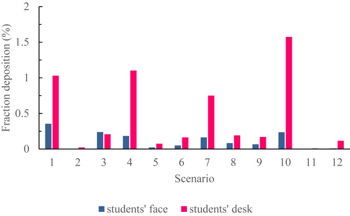
Fig. 10 shows the fraction of particles deposited on students' faces and desks for different scenarios. As shown, there are the highest percentages of deposited particles in the students' faces in scenarios 1, 10, 3, and 7. Furthermore, the percentages of particles deposited on desks 10, 4, 1, and 7 are respectively maximal among the scenarios. However, scenarios 2, 11, 5, and 12 show the lowest percentages of particles deposited on faces and desks; hence, the four scenarios can be introduced as the most desirable states. The results indicate that the lowest and highest amounts of particles deposited on the face and desks occur in a specific scenario. As shown, the lowest state belongs to scenarios 2 and 11 and the highest state belongs to scenarios 10 and 1.
Fig. 10.
Fraction of particles deposited on students' faces and desks for different scenarios.
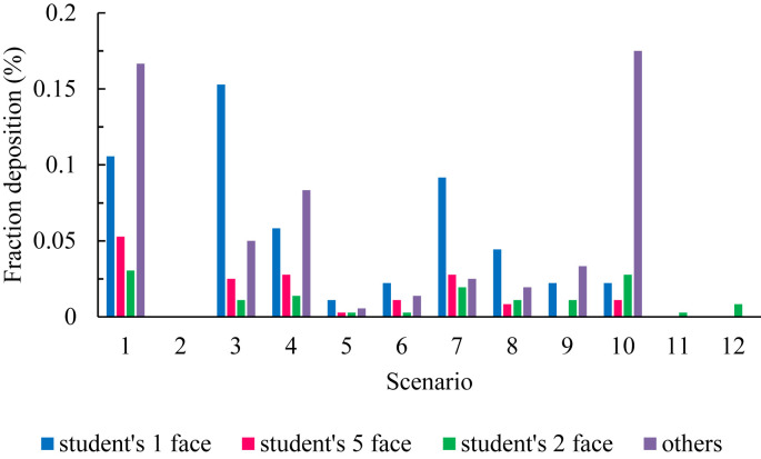
Fig. 11 is a comparison the fraction of particles deposited on the faces of three high-risk students across all scenarios with other students' face. As shown in the figure, the total fraction of particles deposited on the faces of students 1, 2, and 5 is higher than the sum of other students. Therefore, it can be concluded that these three students have the highest probability of infection in all scenarios. According to the figure, there is no particle deposition on the students' faces in scenario 2, and it can be considered an optimal state. Comparing these scenarios, we can conclude that scenarios 2, 11, 12, and 5 showed the lowest fractions of particles deposited on students' faces.
Fig. 11.
Comparison the fraction of particles deposited on the faces of three high-risk students across all scenarios with other students' face.
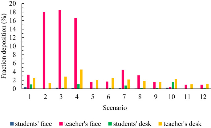
A comparison between the fraction of particles deposited on the students' faces and desks across all scenarios relative to the injector is illustrated in Fig. 12 . In this figure, the fractions of particles deposited on the teacher's faces or desks were greater than the students in all scenarios were. Therefore, it can be concluded that the fractions of particles deposited around a person injecting the contaminated particles in the environment will be higher than the others. The sum of these particle fractions during scenarios 2, 3, and 4 is higher than other scenarios. As illustrated, this figure also shows that no particles deposited on the students' desks and faces in scenario 2. Furthermore, it can be noted that the lowest fraction of particles was deposited on the teacher's face and desk during scenarios 11, 12, 5, and 9. Moreover, the lowest amount of particles deposited on the teacher's face belonged to scenario 10.
Fig. 12.
Comparison between the fraction of particles deposited on the students' faces and desks across all scenarios relative to the injector (teacher).
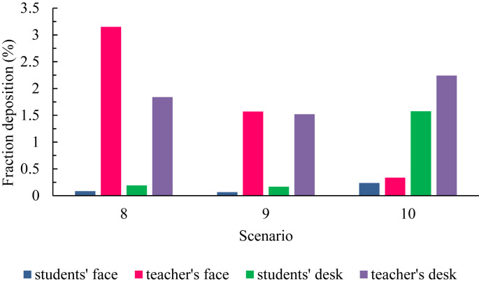
Fig. 13 is a comparison between the fraction of particles deposited on the teacher's face and desk and students' faces and desks during the 3 scenarios, 8, 9, and 10. In all three scenarios, the fraction of particles deposited on the teachers' faces and desks is higher than the students' faces and desks. Furthermore, in scenarios 8 and 9, the fraction of particles deposited on the teacher's face is more than the particles deposited on the teacher's desk and students' faces, but the fraction of particles deposited on the teacher's desk is more than other cases in scenario 10. According to the above figure, we can conclude that the fraction of particles deposited on the teacher's face decreases as the scenarios progress, but it was in contrast to students.
Fig. 13.
Comparison between the fraction of particles deposited on the students' faces and desks across 8, 9 and 10 scenarios relative to the injector (teacher).
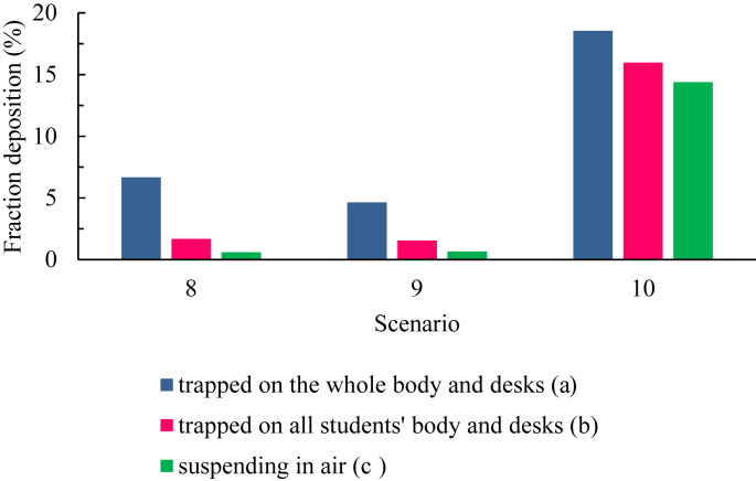
The fraction of particles deposited on the body of all individuals (including teachers and students) along with their desks (mode a) and the body and desks of all students (mode b), and the fraction of airborne particles (mode c) from the total particles injected in three scenarios, 8, 9, and 10, is illustrated in Fig. 14 . In all three scenarios, the fraction of deposited particles on mode (a) is compared to mode (b) and mode (c). It is noteworthy that the suspended particles in the environment increase with a slight slope from scenario 8 to 9. While the slope of this trend is very steep from scenario 9 to 10, indicating that there is a fraction of particles, that are not specified and are still suspended in the classroom air, in scenario 9 more than the previous two scenarios. In all three scenarios, the fraction of suspended particles is less than modes (a) and (b) in a way that among these three scenarios, scenario 9 has the lowest fraction of particles deposited during these modes in comparison with scenarios 8 and 10. Therefore, scenario 9 is optimal in comparison with the other two.
Fig. 14.
Comparison between particles trapped on all surfaces of students' bodies with the bodies of all individuals and suspending particles in three scenarios: 8, 9 and 10.
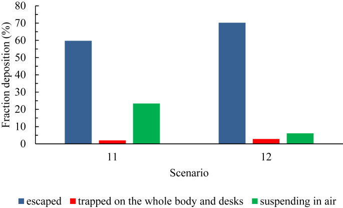
The fraction of out of class particles deposited on all bodies and desks and suspended in the classroom air for all particles injected into the environment during scenarios 11 and 12, is shown in Fig. 15 . As shown, doubling the particle tracking time in the classroom environment (scenario 12) decreases the fraction of airborne particles almost by four times (from 23.37% to 6.06%), and the fraction of output and deposited particles on all desks and bodies rise with a gentle slope.
Fig. 15.
Comparison between the fractions of particles trapped on the whole bodies and desks with escaped and suspending across 11 and 12 scenarios.
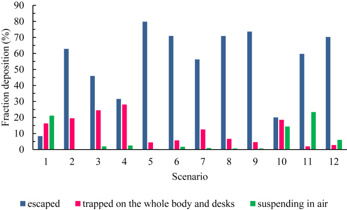
Fig. 16 shows the fraction of out of class particles trapped on all surfaces of the body and the upper surface of the desks as well as the fraction of airborne particles per total particles injected in all scenarios. As shown, the fraction of the output particles from the classroom is maximal in scenarios 5, 9, and 8. In scenarios 11, 1, and 10, we face the largest fraction of suspended particles respectively. For particles deposited on the surfaces, scenarios 4, 3, and 2 have higher percentages, and conversely, scenarios 11, 12, and 5 have the lowest fraction of particles deposited on the surfaces. It is worth noting that there is the lowest fraction of particulate matter equal to 0.32 percent and 0.18 percent in the air in scenarios 2 and 5 respectively, indicating that most particles are specified during these two scenarios. According to the above explanations, it can be concluded that scenario 5 is the most optimal state in terms of particle fraction discussed in the figure.
Fig. 16.
Comparison between the fractions of particles escaped with trapped on all surfaces of the body and desks and suspended in air for all scenarios.
3.2. State B (cough)
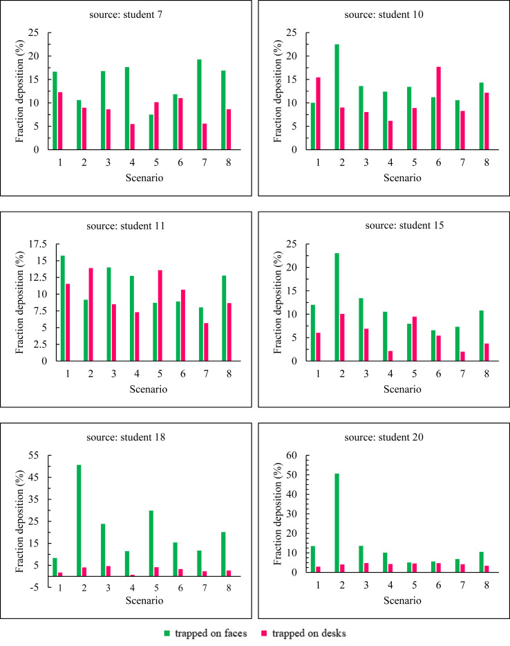
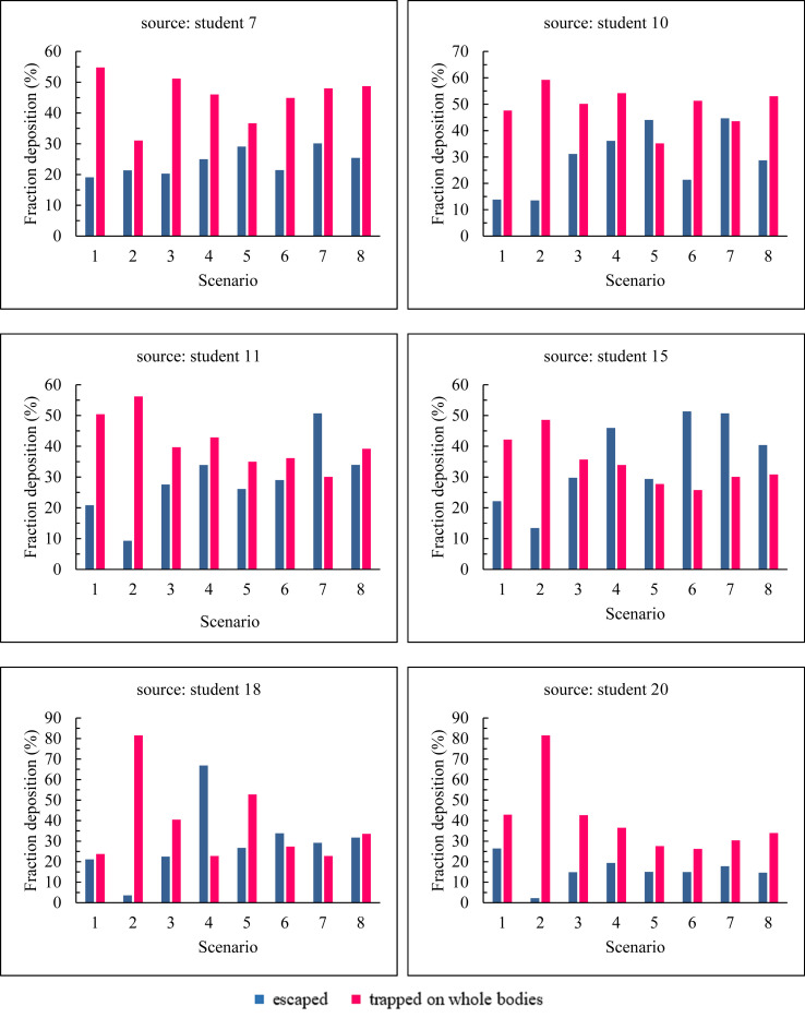
The results in Fig. 17, Fig. 18 indicate the fraction of particles deposited on the faces, desks, and body surfaces and the fraction of particles emitted from the classroom environment along with the particles deposited overall body when we have six different sources of cough for eight different scenarios. According to the figure, there are the following tips separately for six sources of cough.
Fig. 17.
The fraction of particles deposited on the faces and desks of people for six sources of cough and eight different scenarios.
Fig. 18.
The fraction of escaped particles and the fraction of particles deposited overall body of individuals for six sources of cough and eight different scenario.
First time, student 7 is the source of cough. According to Fig. 17, the total fraction of particles deposited on the students' faces and desks in scenario 1 is higher than in other scenarios. In this scenario, the fraction of particles deposited on the students' bodies is also higher than in other scenarios. However, scenarios 2 and 5 have a more favorable status than the rest of the scenarios and scenario 2 has the lowest particles deposited on the students' bodies. In scenario 5, there are the lowest total fraction of particles deposited on faces and desks. According these results, the maximum fractions of output particles belong to scenarios 7 and 5 and the highest fractions of particles deposited on the body belong to scenarios 1 and 3 respectively. At last, with considering the results of Fig. 17, Fig. 18, we can conclude that scenario 1 is the worst case and scenarios 5 and 2 are respectively the best cases in terms of staying healthy against contaminated particles during coughing.
Second time, student 10 is the source of cough. As shown in Fig. 17, the total fraction of particles deposited on the students' faces and desks are higher in scenarios 2, 6, and 8 respectively than in other scenarios, while scenarios 7 and 4 have the lowest amounts respectively. As illustrated, the fractions of the output particles are maximum in scenarios 7, 6, and minimum in scenarios 2 and 1 respectively. This result indicates that the fractions of particles deposited in scenarios 2 and 1 are much higher than scenarios 7 and 6 as shown in the figure. In this case, we can conclude that people in the classroom during scenario 7 are at lower risk than the rest of the scenarios, while this possibility is higher for scenario 2.
Third time, student 11 is the source of cough. As illustrated in Fig. 17, Fig. 18 for this case, individuals are more likely to be infected in scenarios 1 and 2 respectively than in other scenarios. Because the deposited of a large fraction of particles on the faces, desks, and body (as shown in Fig. 17) and also the lower amount of particles emitting from the classroom during these two scenarios than the other scenarios.
Furth time, student 15 is the source of cough. According to the results of Fig. 17, Fig. 18, the fraction of particles deposited on the faces, desks, and body e in scenario 2 has the highest rate. As shown in Fig. 18, we face the least output particles in this scenario and thus the highest amount of particles deposited, but individuals in scenario 6 face a safer environment than the rest of the scenarios.
Fifth time, student 18 is the source of cough. In this case as shown in Fig. 17, the fractions of particles deposited on the individuals' faces and bodies are maximal for scenario 2, and we have the minimum amount of output particles during this scenario according to Fig. 18. However, the fraction of deposited particles and the output particles have the lowest and highest levels respectively in scenario 4, and we can conclude that fewer people are contaminated with particles during this scenario.
Sixth time, student 20 is the source of cough. According to Fig. 17, Fig. 18, the fraction of particles deposited on the faces, desks, and bodies and also the amounts of particles emitted from the classroom are maximal during scenario 5, and vice versa, they are minimal in scenario 2. Therefore, we can conclude that scenarios 5 and 2 are respectively the most desirable and worst scenarios in terms of risk.
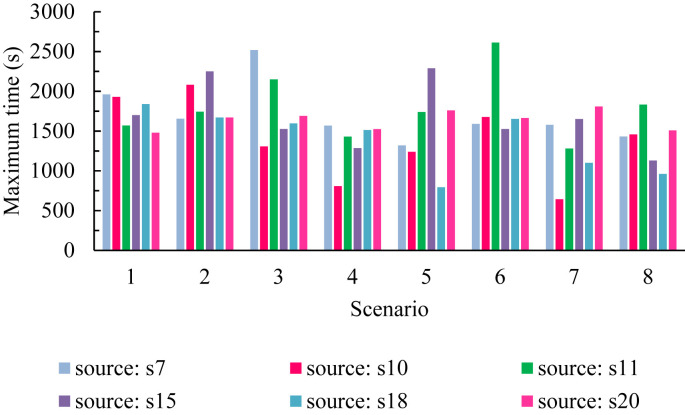
As mentioned in the previous sections, we steady state modeled the cough mechanism in the present study. Fig. 19 shows the results for the maximum time necessary for examining the last cough particle in the classroom (particle exit or deposited) for different scenarios. Table 5 presents a summary of these results for scenarios.
Fig. 19.
Maximum time required to assign the last cough particle in the class (particle escape or deposition) for different scenarios.
Table 5.
Maximum particle determination time.
| Scenario | 1 | 2 | 3 | 4 | 5 | 6 | 7 | 8 | |
|---|---|---|---|---|---|---|---|---|---|
| Source | 7 | 15 | 7 | 7 | 15 | 11 | 20 | 11 | |
| Maximum time (min) | 32.67 | 37.5 | 42 | 26.15 | 38.17 | 43.55 | 30.17 | 30.52 | |
According to Fig. 19 and the data in Table 6 , the longest time for the particles to be examined belongs to scenario 6 and student 11 coughs. In this case, it takes 43.55 min for the last particle to be absorbed or exit, but the shortest time occurs in scenario 7 and due to student 10 coughs.
Table 6.
Maximum and minimum time belonging to the particles.
| scenario | 1 | 2 | 3 | 4 | 5 | 6 | 7 | 8 | |
|---|---|---|---|---|---|---|---|---|---|
| max | source | 7 | 15 | 7 | 7 | 15 | 11 | 20 | 11 |
| time (min) | 32.67 | 37.5 | 42 | 26.15 | 38.17 | 43.55 | 30.17 | 30.52 | |
| min | source | 20 | 20 | 10 | 10 | 18 | 15 | 10 | 18 |
| time (min) | 24.67 | 24.67 | 21.78 | 13.46 | 13.23 | 25.43 | 10.73 | 16.02 | |
4. Discussion
The present section provides the results of the resolution with the help of color contours, indicating the percentage of risk of diseases for different scenarios in two states A and B, and presents arguments for the resolution.
4.1. State A
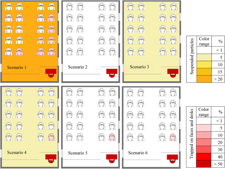
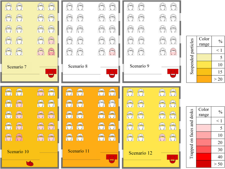
Fig. 20, Fig. 21 shows the contour of the fraction of suspended particles deposited on the faces and desks for the speaking to better clarify the results and determine the most favorable and worst conditions. An advantage of providing these contours is that the results are more tangible for researchers and readers. When all windows of the classroom are closed, the only way for exiting the flow from the classroom is at the bottom of the door (equalizer) that reduces the output flow capacity, and increases the shelf life of particles inside the classroom. So the particles scattered in the environment have less inertia, the energy of the fluid mass overcomes the inertia of the particles and forces them to follow the flow patterns. As the door equalizer is the only way of flow exit during this scenario, we can see that those in the left half of the classroom in cough are at much higher risk than right side. In speaking, the distance between the particle injection site and the equalizer is greater and the output capacity is low, thus the resulting flow patterns tend to scatter the particles in different areas of the classroom. Therefore, it is cause the number of people at high-infected risk in this case and scenario increase in terms of both the fraction of deposited particles and the fraction of airborne particles. Increasing the flow output capacity of the classroom with opening one of the windows in scenarios 2, 3, and 4, the shelf life of the particles also decreases. A comparison of the results between these three scenarios suggests that since the particle injection location during speaking is close to the opened window (in scenario 2), the resulting flow patterns act in a way that they exit particles before they are scattered in different areas of the classroom. In addition to, the distance between the open windows and the injection site is greater in scenarios 3 and 4, and the particles travel a longer path to exit the window than the scenario 2, and this causes more scattering of particles in the environment and increases their shelf life. According to the above discussions, the following classification can be performed in terms of risk (both in terms of the fraction of deposited particles and in terms of fraction of suspended particles) for these three scenarios.
Fig. 20.
Contours of fraction deposited particles on surfaces with high-level risk (faces and desks) and suspending particles in air for first six scenarios in state A.
Fig. 21.
Contours of fraction deposited particles on surfaces with high-level risk (faces and desks) and suspending particles in air for second six scenarios in state A.
Scenario 2 < scenario 3 < scenario 4
As the source of cough is different, the results are different from speaking, but among these three scenarios, scenario 2 has a higher risk of infection in the cough.
As shown in this figures, the largest amounts of deposited pathogenic particles belong to the injector in all scenarios. Furthermore, it is observed that pollution is insignificant in terms of airborne particles in scenarios 9, 8, 6, 5, and 2. In these scenarios, only one student (student 1) is exposed to contaminated particles by a faction of below 5% for the total particles deposited on faces and desks (except for scenario 2 in which none of the students are affected by the particles).
In scenarios 5, 6, and 7, where the number of open windows has increased to two, the flow output capacity has also increased, leading to the reduction of the shelf life of the suspended particles compared to the previous four scenarios. On the other hand, because the flow patterns in these scenarios have two major exit pathways, it has relatively increased the particle dispersion (especially in scenarios 7).
We encounter the highest level of airborne particulate pollution in scenarios 11, 1, and 10 respectively among which the students in scenario 10 (eleven students infected with the virus with deposited particles of below 5% and a student below 10%) have the highest risk of infection. Monitoring the fraction of particles deposited on faces and desks indicates that scenarios 10 and 1 have the number of people involved in a greater fraction of the particles. A noteworthy point in the results presented in this figure is related to scenario 2, which is in a better position than the rest of the scenarios in terms of both the fraction of airborne particles and the deposited particles. Therefore, we can conclude that the risk of disease is minimum and maximum in scenarios 2 and 10 respectively. Comparing the contours in different scenarios, we conclude that students in front of the teacher (injector) generally have a high risk of infection, and their number and percentage of risk strongly follow the flow patterns in each scenario. For instance, in scenario 1, where the only way out for flow and particles is through the part at the bottom of the door (equalizer), flow patterns tend to disperse the particles in more areas of the class. Therefore increases the number of people at high risk of infection due to the low capacity of the indoor air outlet (as shown in Fig. 16, there are more fraction of suspended particles in scenario 1 and 11, thereby increasing the shelf life of the particles). Conversely, in scenario 2, where window 1, the outflow capacity is higher, and since the injector is by the window, most of the particles are discharged in this way along with the flow patterns (as shown in Fig. 16), leading to a risk of less than 1% for students either by deposited particles or airborne particles in this scenario. In another example of comparing scenarios 3 and 11, there is a similar risk of contamination in both of them in terms of the fraction of deposited particles, and the only difference is in the risk of people getting airborne particles. As shown, this risk for scenario 11 is higher than scenario 3 according to the resulting flow patterns. According to the comparison of the three scenarios 8, 9, and 10, we can conclude that the percentages of people at risk in scenarios 8 and 9 are the same. Whereas when the teacher is as an injector in the position in scenario 10, airflow patterns scatter particles in different areas of the classroom, leading to increase the number of students at a risk of more than 1%, and this comparison reflects the impact of the injection site in speaking.
For scenarios 8, 9, and 10, all three windows are open. In these scenarios, we measured the impact of the teacher position (including sitting or standing). In scenario 8, the injection site is still the same as the previous seven scenarios (sitting on a chair behind a desk). In scenario 9, the teacher speaks standing instead of sitting behind the desk. The comparison between these two scenarios indicates a relative improvement in the risk of individuals. Whereas, when the teacher is moved to the location (0, 0.3, and 0.5) in scenario 10 (in terms of class width in the middle of the class), the resulting flow patterns cause particles to scatter in more areas of the classroom and the students have the highest risk. Therefore, we never recommend this scenario for the conditions considered in the present study.
In the last two scenarios, the natural airflow entering from the classroom door is examined by removing the mechanical ventilation system. Due to the thermal comfort in these scenarios, the windows are assumed to be at their maximum opening states. Scenario 11 is done for 10 min in pursuit of particles, but since according to the results, most of the particles are suspended in the air inside the classroom during this time and this increases the likelihood of infection, scenario 12 is performed for 20 min of particle chasing to clarify the particle state at the next times. The results indicate that the risk of individuals' infection is more related to suspended particles than deposited particles in this scenario.
4.2. State B
In this case, there are scenarios with a high risk of infection for different sources of cough, and scenarios absent in the results of this section are in a better situation (usually with one or two people with a risk of infection between 5% and 1%) in terms of risk.
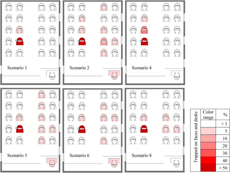
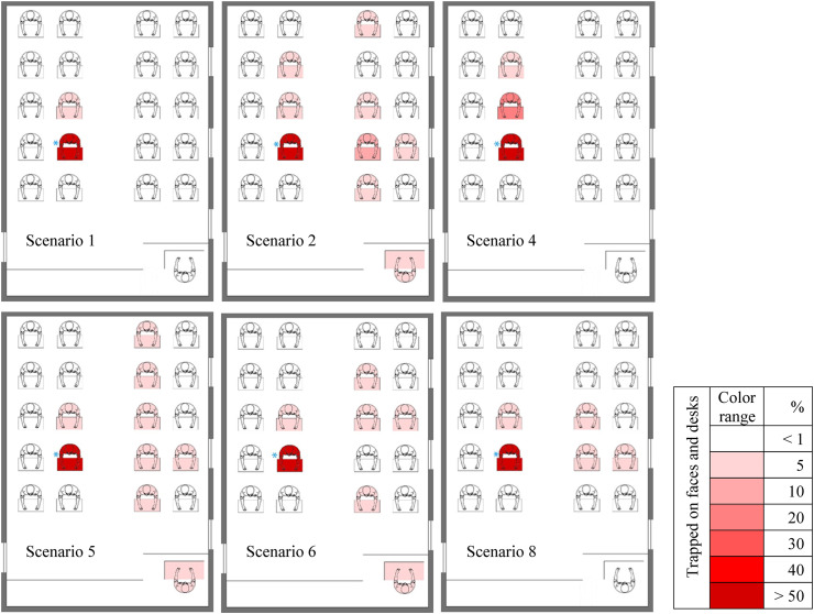
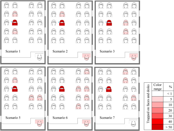
Fig. 22 shows the fraction distribution contours of particles deposited on the individuals' faces and desks (sensitive and high risk surfaces) for student 7 cough in the scenarios with the highest number of infected people (source of cough in different scenarios is marked with a blue star). As shown in, the largest fractions of deposited particles belong to the injector in all scenarios. Furthermore, there are a large number of people infected with droplets from coughing in scenarios 2, 5, and 6. Moreover, contours in these three scenarios are almost similar to scenarios 2 and 5, but we can conclude that due to the infection of a student with a fraction of deposited particles of 5%–10% in scenario 2 (student 6), this scenario has a higher risk than the others do. According to the flow patterns in all three scenarios, the teacher also has a fraction of deposited particles below 5%, while the teacher is at risk of less than 1% in the other three scenarios. According to the comparison of the existing scenarios and the flow patterns created in the classroom, the students on the right side of the injector (student 7) are at lower risk than the rest of the individuals in the classroom. Explaining the reason for the difference in the risk percentages of student 11 (a student behind the injector) in scenarios 1 and 4, we can argue that since most flow patterns and particles scattered in the environment tend to go out of window 3 in scenario 4 and as the location of this window is in the back of student 7, the injected particles follow these patterns, as result student 11 faces a higher risk of infection (between 5% and 10%) than scenario 1 where there is the output flow only through the equalizer.
Fig. 22.
Contours of fraction deposited particles on danger surfaces (faces and desks) for scenarios with high-level risk when cough source is student 7.
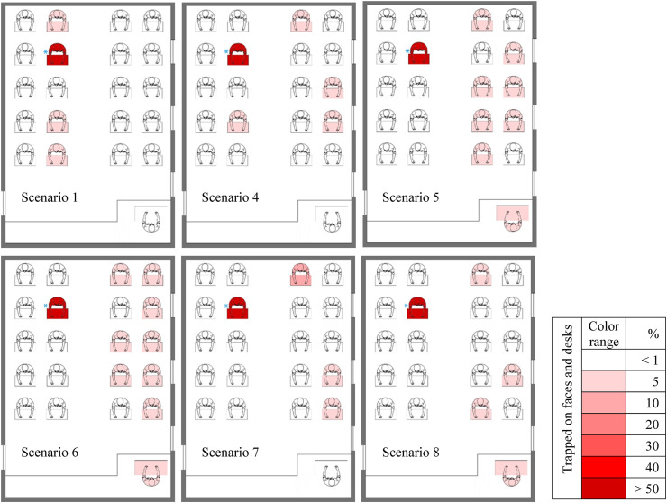
As shown in Fig. 23 , student 10 is the source of cough. In this case, the number of scenarios with high risk is two, and those in Scenario 1 are at the highest risk. In scenario 2, the risk of teacher infection is higher than in scenario 1. As stated in the previous results, the highest number of deposited particles belongs to the injector in this figure. As illustrated, the students next to the right and left walls of the classroom have a lower risk of infection to the other students. The figure above shows the high impact of flow patterns generated during both scenarios on the results. As shown, the individuals in scenario 1 are on the flow output path (only the equalizer at the bottom of the classroom in this case) and at high risk. About the high risk of infecting two students behind the injecting student, the shelf life of the particles in the classroom is longer since the output capacity is lower in this scenario and this raises the probability of infection. In scenario 2, where window 1 is also open, the particle output capacity increases (compared to scenario 1), and most particles tend to come out of window 1 according to the flow patterns, and these two factors cause the particles to condense in the corners of the window and more particles to deposited on the teacher's face and desk.
Fig. 23.
Cantors of fraction deposited particles on danger surfaces (faces and desks) for scenarios with high-level risk when cough source is student 10.
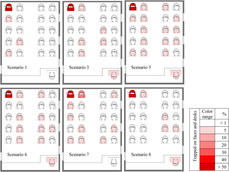
The contour fraction of particles deposited on the individuals' faces and desks in the classroom for scenarios at a high risk of student 11 coughs, is illustrated in Fig. 24 . Among these scenarios, the probability of disease in individuals in scenario 6 is higher than in other scenarios, and the teacher's face a fraction of deposited particles above 1% in all scenarios except for scenarios 1 and 7. Another important point is the low risk of infection for students present in the right of the injecting student (student 11) in all scenarios. Therefore, in addition to the students on the right side of student 11, students in the right half of the class also face a fraction of infection less than 1% in scenarios 1 and 2. In the figure above, we can see the effects of flow patterns in scenarios 1 and 2. According to the results, the difference between the two scenarios in terms of risk is related to the student 7 and the teacher. In scenario 1, it is observed that the flow patterns coming out of the door equalizer also lead the particles to the output, prevent the scattering of particles in different areas of the class, and thus lead to a lower number of people at high risk. However, in scenario 2, the flow streamlines in addition to the door equalizer can exit the window next to the teacher and the results indicate that most particles exit along with the flow patterns, the scattering of particles inside the classroom increases, and the teacher is at high risk (below 5%) due to the higher output surface of the windows.
Fig. 24.
Contours of fraction deposited particles on danger surfaces (faces and desks) for scenarios with high-level risk when cough source is student 11.
Fig. 25 presents the distribution contours of the fraction of particles deposited on the individuals' faces and desks (sensitive and high-risk surfaces) per student 15 cough in scenarios with the highest risk of infection. As shown in this figure, the largest fraction of deposited particles belongs to the injector. Among these scenarios and according to the flow patterns, the individuals present in scenarios 5 and 6 are at high risk. Another important point about these two scenarios is their similar behavior according to the results so that we can conclude that particle scattering follows a similar trend during these two scenarios, and most individuals in the right half of the classroom are at higher risk. According to Fig. 11, the individuals in the left half of the classroom face risk of less than 1% due to flow patterns in all scenarios except for scenarios 1 and 4. Except for three scenarios 1, 4, and 7, the teacher has a fraction of deposited particles less than 1% in the other three scenarios. According to this figure, the fraction of deposited particles is between 5% and 10% for only student 18 in scenario 7 (except for the injecting student). In general, the openness of the windows causes the flow patterns to be directed towards them and forces particles to follow themselves by affecting the particles scattered in the environment. In addition to, since these particles have less inertia; hence, there is more scattering of these particles in areas close to windows, and this scattering eventually leads to more people being infected in these areas.
Fig. 25.
Contours of fraction deposited particles on danger surfaces (faces and desks) for scenarios with high-level risk when cough source is student 15.
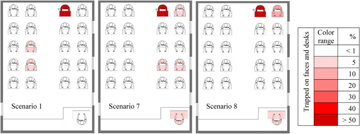
According to the comparison of the fractional contours of the deposited particles in the scenarios presents in Fig. 26 , where the student 18 is the source of cough, due to the openness of at least two windows in scenarios 7 and 8, the resulting flow patterns are in a way that infected particles are more pushed to the window and the students in the left half of the classroom are at a lower risk. During these two scenarios, the teacher is also at higher risk (under 5%). However, since none of the windows is open during scenario 1 and the only way for the exit of particles is through the equalizer, we can see that as the flow path is directed towards this output, the particles also move along the flow patterns. Unlike the previous two scenarios, the individuals in the right half of the classroom are at a lower risk.
Fig. 26.
Cantors of fraction deposited particles on danger surfaces (faces and desks) for scenarios with high-level risk when cough source is student 10.
Fig. 27 illustrated the results when the student 20 is source of cough. As shown, the number of people at a risk of more than 1% in all scenarios is higher than when other students are the sources of cough, indicating the effect of the cough place. According to the comparison of the results, the risk of infection is lower for individuals in the right half of the classroom in scenario 1, indicating the effects of flow patterns on particle scattering. In scenario 5, the flow pattern is distributed in a way that the particles are scattered throughout the classroom, increasing the number of individuals at risk of over 1%. A similar result of this scenario can be seen in scenarios 6 and 7.
Fig. 27.
Contours of fraction deposited particles on danger surfaces (faces and desks) for scenarios with high-level risk when cough source is student 20.
5. Conclusion
In the present study, we examined the effect of natural and mechanical ventilation inside a classroom on the transmission, distribution, and shelf life of coronavirus particles during speaking and cough. Based on the results, the following conclusions are redrawn:
-
•
In speaking for all the scenarios tested, the results indicate that opening one or two windows next to the injector (teacher) has the greatest effect on the rapid exit of particles and the improvement of conditions, and the teacher talking while standing somewhat improves the situation compared to the sitting position. Furthermore, eliminating the mechanical ventilation system and applying only natural airflow increases the shelf life of particles in the environment and increases the risk of infection.
-
•
According to the results of cough, the risk of infection is often lower in the right half of the classroom than other individuals for each source of cough during all windows are closed. The worst situation in this scenario occurs when student in the corner of the classroom is the source of cough. In other scenarios, more areas are usually affected by particle scattering due to the resulting flow patterns.
-
•
The results indicate that the largest fraction of particles on the particle injectors' desks and faces in all scenarios.
-
•
The opening of the window next to the teacher (the infected person in this study) has the greatest impact on the exit of infected particles. Moreover, during this scenario, fewer people are at risk.
-
•
With the addition of open windows (more than one window), the distribution of particles inside the domain increases and the risk of infecting residents also increases.
-
•
Speaking the teacher while standing at a desk relative to the sitting position relatively reduces the risk of infecting residents.
-
•
Lack of air conditioning increases the shelf life of the particles and consequently the risk of infection.
-
•
In all scenarios, whether speaking or coughing, after the injector residents close to the infected person are at greater risk.
-
•
When all the windows are closed, due to the low output capacity, the particles spread in all areas of the domain and increase the risk of infection. Therefore, it is recommended that the window be open in indoors environment (especially the window next to the speaker).
This study emphasizes the impact and importance of having an indoor ventilation system, and the results indicate that if the window next to an injector of contaminated particles is open, the risk of infection of other individuals greatly decreases.
Therefore, it is recommended that people should not be present in high-risk areas and should wear masks to reduce the possibility of infection because the room air cannot be completely cleaned of pathogenic particles.
CRediT authorship contribution statement
Mahdi Ahmadzadeh: Methodology, Validation, Software, Data curation, Investigation, Writing – original draft, Writing – review & editing, Revised. Emad Farokhi: Validation, Writing – original draft, Software, Resources, Formal analysis. Mehrzad Shams: Supervision, Project administration, Conceptualization, Revised.
Declaration of competing interest
The authors declare that they have no known competing financial interests or personal relationships that could have appeared to influence the work reported in this paper.
Handling editor: Prof. Jiri Jaromir Klemeš
References
- Abboah-Offei M., et al. A rapid review of the use of face mask in preventing the spread of COVID-19. Int. J. Nurs. Stud. Adv. 2021;3:100013. doi: 10.1016/j.ijnsa.2020.100013. August 2020. [DOI] [PMC free article] [PubMed] [Google Scholar]
- Asadi S., et al. Aerosol emission and superemission during human speech increase with voice loudness. Sci. Rep. 2019;9(1):1–10. doi: 10.1038/s41598-019-38808-z. [DOI] [PMC free article] [PubMed] [Google Scholar]
- Bake B., et al. Exhaled particles and small airways. Respir. Res. 2019;20(1):1–14. doi: 10.1186/s12931-019-0970-9. [DOI] [PMC free article] [PubMed] [Google Scholar]
- Bhattacharyya S., et al. A novel CFD analysis to minimize the spread of COVID-19 virus in hospital isolation room. Chaos, Solit. Fractals. 2020;139:110294. doi: 10.1016/j.chaos.2020.110294. [DOI] [PMC free article] [PubMed] [Google Scholar]
- Borro L., et al. ‘The role of air conditioning in the diffusion of Sars-CoV-2 in indoor environments: a first computational fluid dynamic model, based on investigations performed at the Vatican State Children's hospital’. Environ. Res. 2021;193 doi: 10.1016/j.envres.2020.110343. [DOI] [PMC free article] [PubMed] [Google Scholar]
- Bourouiba L. Turbulent gas clouds and respiratory pathogen emissions: potential implications for reducing transmission of COVID-19. JAMA - J. Am. Med. Assoc. 2020;323(18):1837–1838. doi: 10.1001/jama.2020.4756. [DOI] [PubMed] [Google Scholar]
- Buonanno G., Morawska L., Stabile L. vol. 145. Environment International; 2020. p. 106112. (Quantitative Assessment of the Risk of Airborne Transmission of SARS-CoV-2 Infection: Prospective and Retrospective Applications). June. [DOI] [PMC free article] [PubMed] [Google Scholar]
- Chan T.K. Universal masking for COVID-19: evidence, ethics and recommendations. BMJ Glob. Health. 2020;5(5):1–6. doi: 10.1136/bmjgh-2020-002819. [DOI] [PMC free article] [PubMed] [Google Scholar]
- Dehbi A. Prediction of extrathoracic aerosol deposition using RANS-random walk and les approaches. Aerosol. Sci. Technol. 2011;45(5):555–569. doi: 10.1080/02786826.2010.550962. [DOI] [Google Scholar]
- Diwan S.S., et al. Understanding transmission dynamics of COVID-19-type infections by direct numerical simulations of cough/sneeze flows. Trans. Indian Nat. Acad. Eng. 2020:255–261. doi: 10.1007/s41403-020-00106-w. [DOI] [PMC free article] [PubMed] [Google Scholar]
- Elghobashi S. On predicting particle-laden turbulent flows. Appl. Sci. Res. 1994;52(4):309–329. doi: 10.1007/BF00936835. [DOI] [Google Scholar]
- Gralton J., et al. The role of particle size in aerosolised pathogen transmission: a review. J. Infect. 2011:1–13. doi: 10.1016/j.jinf.2010.11.010. [DOI] [PMC free article] [PubMed] [Google Scholar]
- Greifzu F., et al. Assessment of particle-tracking models for dispersed particle-laden flows implemented in OpenFOAM and ANSYS FLUENT. Engi. Appl. Comput. Fluid Mech. 2016;10(1):30–43. doi: 10.1080/19942060.2015.1104266. [DOI] [Google Scholar]
- Gupta J.K., Lin C.H., Chen Q. Flow dynamics and characterization of a cough. Indoor Air. 2009;19(6):517–525. doi: 10.1111/j.1600-0668.2009.00619.x. [DOI] [PubMed] [Google Scholar]
- Hang J., et al. Potential airborne transmission between two isolation cubicles through a shared anteroom. Build. Environ. 2015;89:264–278. doi: 10.1016/j.buildenv.2015.03.004. [DOI] [PMC free article] [PubMed] [Google Scholar]
- Hedrick R.L., et al. Ventilation for acceptable indoor air quality. ASHRAE Standard. 2013 www.ashrae.org 2013(62.1-2013). Available at. [Google Scholar]
- Jacob S., Yadav S.S., Sikarwar B.S. Springer Singapore; 2019. Design and Simulation of Isolation Room for a Hospital Á Infection Á Isolation Á Ventilation Á Air Conditioning Á. [DOI] [Google Scholar]
- Jankovic L. Experiments with self-organised simulation of movement of infectious aerosols in buildings. Sustainability. 2020;12(12) doi: 10.3390/su12125204. [DOI] [Google Scholar]
- Jayaweera M., et al. Transmission of COVID-19 virus by droplets and aerosols: a critical review on the unresolved dichotomy. Environ. Res. 2020;188:109819. doi: 10.1016/j.envres.2020.109819. [DOI] [PMC free article] [PubMed] [Google Scholar]
- Jin C., Potts I., Reeks M.W. A simple stochastic quadrant model for the transport and deposition of particles in turbulent boundary layers. Phys. Fluids. 2015;27(5):1–26. doi: 10.1063/1.4921490. [DOI] [Google Scholar]
- Kohanski M.A., Lo L.J., Waring M.S. Review of indoor aerosol generation, transport, and control in the context of COVID-19. Int. Forum Allergy Rhinol. 2020;10(10):1173–1179. doi: 10.1002/alr.22661. [DOI] [PMC free article] [PubMed] [Google Scholar]
- Leung N.H.L., et al. Respiratory virus shedding in exhaled breath and efficacy of face masks. Nat. Med. 2020;26(5):676–680. doi: 10.1038/s41591-020-0843-2. [DOI] [PMC free article] [PubMed] [Google Scholar]
- Liu L., et al. Evaporation and dispersion of respiratory droplets from coughing. Indoor Air. 2017:179–190. doi: 10.1111/ina.12297. [DOI] [PubMed] [Google Scholar]
- Liu Z., et al. Experimental and numerical study of potential infection risks from exposure to bioaerosols in one BSL-3 laboratory. Build. Environ. 2020;179(April) doi: 10.1016/j.buildenv.2020.106991. [DOI] [PMC free article] [PubMed] [Google Scholar]
- Mahdavimanesh M., Noghrehabadi A.R., Behbahaninejad M., Ahmadi G., Dehghanian M. Lagrangian particle tracking: model development. Life Sci. J. 2013;10(8s):34–41. 2013. [Google Scholar]
- Subramaniam Shankar. Lagrangian–Eulerian methods for multiphase flows.pdf. Elsevier Sci. 2012;1(March):75. [Google Scholar]
- Shao S., et al. Risk assessment of airborne transmission of COVID-19 by asymptomatic individuals under different practical settings. J. Aerosol Sci. 2021;151:105661. doi: 10.1016/j.jaerosci.2020.105661. July 2020. [DOI] [PMC free article] [PubMed] [Google Scholar]
- Shi P., et al. 2020. Since January 2020 Elsevier Has Created a COVID-19 Resource Centre with Free Information in English and Mandarin on the Novel Coronavirus COVID- 19 . The COVID-19 Resource Centre Is Hosted on Elsevier Connect , the Company ’ S Public News and Information. (January) [Google Scholar]
- Srebric J., et al. vol. 43. 2008. CFD Boundary Conditions for Contaminant Dispersion , Heat Transfer and Airflow Simulations Around Human Occupants in Indoor Environments; pp. 294–303. [DOI] [Google Scholar]
- Wang J.X., Cao X., Chen Y.P. An air distribution optimization of hospital wards for minimizing cross-infection. J. Clean. Prod. 2021;279:123431. doi: 10.1016/j.jclepro.2020.123431. [DOI] [PMC free article] [PubMed] [Google Scholar]
- Yan Y., et al. 2020. Since January 2020 Elsevier Has Created a COVID-19 Resource Centre with Free Information in English and Mandarin on the Novel Coronavirus COVID- 19 . The COVID-19 Resource Centre Is Hosted on Elsevier Connect , the Company ’ S Public News and Information. (January) [Google Scholar]
- Zhang Y., et al. Distribution of droplet aerosols generated by mouth coughing and nose breathing in an air-conditioned room. Sustain. Cities Soc. 2019;51:101721. doi: 10.1016/j.scs.2019.101721. [DOI] [Google Scholar]
- Zhu N., et al. A novel coronavirus from patients with pneumonia in China, 2019. N. Engl. J. Med. 2020;382(8):727–733. doi: 10.1056/nejmoa2001017. [DOI] [PMC free article] [PubMed] [Google Scholar]
- Zu Z.Y., Jiang M.D., Xu P.P., Chen W., Ni Q.Q., Lu G.M., Zhang L.J. Coronavirus disease 2019 (COVID-19): a perspective from China. Radiology. 2020;296:200490. doi: 10.1148/radiol.2020200490. [DOI] [PMC free article] [PubMed] [Google Scholar]


