Abstract
The full-length standing radiograph in an anteroposterior projection is the primary tool for defining and measuring limb alignment with definition of the physiological axes and mechanical and anatomic angles of the lower limb.
We define the deformities of the lower limb and the importance of correct surgical planning and execution.
For patients with torsional malalignment of the lower limb, computerized tomography scan evaluation is the gold standard for preoperative assessment.
Cite this article: EFORT Open Rev 2021;6:487-494. DOI: 10.1302/2058-5241.6.210015
Keywords: alignment, anatomic tibiofemoral angle, deformity, knee, lower limb alignment, mechanical axis angle, radiography
The alignment of the lower limb can be evaluated with standard radiographic techniques. However, the mechanical and anatomic axes of the lower limb are only precisely assessed if the ankle and hip positions are known. Standing views allow the assessment of the tibiofemoral knee compartments states, including the joint space. For evaluation of the patellofemoral joint, skyline or Merchant views are used. However, computerized tomography (CT) and magnetic resonance imaging (MRI) can give more subtle information. Definition of human normal limb alignment and malalignment are formulated from statistics. Thereby, the deformities of the lower limb are defined as a deviation of the physiological axes. Limb alignment deformities may have a congenital or constitutional aetiology. During childhood they may be due to growth disorder with the premature closure of the epiphyseal plate. They are also associated with trauma, metabolic disorders such as rickets, or osteopathies such as renal osteopathy. Systemic myopathies or neurologic pathologies may also be related.
Posttraumatic deformities may occur after florid fracture healing. Other causes may be related to osteonecrosis of the knee, tumours, rheumatoid arthritis, and secondary to cartilage damage that follows major meniscal resections. The ultimate result is the secondary deviation of the mechanical axis of the lower limb.
Defining and measuring limb alignment
The anteroposterior (AP) projection full-length standing radiograph is the primary tool for evaluating the lower limb alignment. Lower limb alignment is best assessed by radiography in AP projection with a horizontally focused X-ray beam of the hip, knee, and ankle with the subject standing upright to support body weight. Patient positioning must be standardized to have reproducible results, especially leg rotation to get a flexion/extension plane aligned in the anterior-posterior direction.
The patella must be aligned in the anteroposterior projection with the centre of the femoral condyles. To achieve this position, 8–10° lateral rotation of the feet is classically needed (Fig. 1a). However, some situations, as seen in torsional deformities, cause medialization or lateralization of the patella. In these cases, the correct position is attained through the internal or external rotation of the lower leg until the patella is centred amongst the femoral condyles (Fig. 1b).1
Fig. 1.
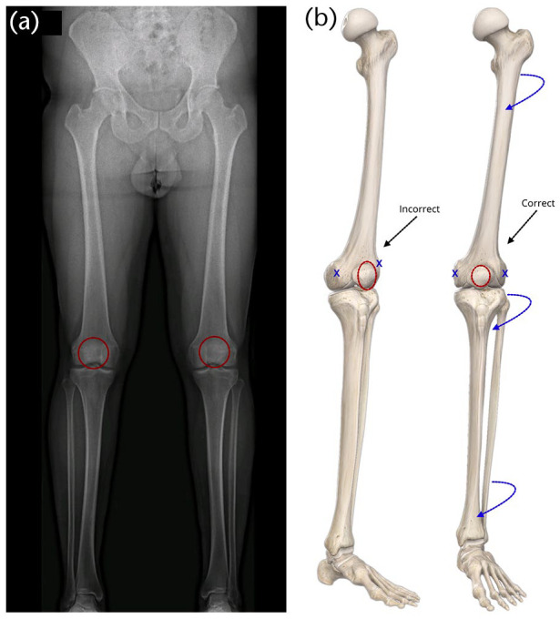
(a) and (b) Correct full-length anteroposterior standing radiograph.
The weight-bearing X-ray of the entire lower limb is mandatory to evaluate the axis. The mechanical axis defined by the hip–knee–ankle line is measured on a full-length standing radiograph in the anteroposterior projection. It is considered a gold standard since it allows for consistent and precise measurement of mechanical tibiofemoral angle and assessment of limb deformities. However, in general practice, alignment is often inaccurately estimated using the anatomic tibiofemoral angle on standard anteroposterior weight-bearing X-rays, eventually causing imprecision in operative planning.1,2
When standard weight-bearing X-rays are used to calculate alignment, the estimated angle on the X-ray is called the anatomic tibiofemoral angle or femoral-shaft–tibial-shaft angle (FS–TS) (Fig. 2). This angle is defined by a line drawn from the centre of the proximal femoral shaft towards the knee and a line from the centre of the tibial shaft distal to the knee. To calculate the femoral and tibial shaft points, it usually is measured 10 cm from the knee joint to adjust the portion of the long-bone shafts commonly seen on a knee X-ray. In the tibia, both the anatomic and mechanical axes are similar.
Fig. 2.

The FS–TS angle is 4–6° valgus compared to the HKA angle.
Notes. FM, femoral mechanical axis; TM, tibial mechanical axis; FA, femoral anatomical axis; TA, tibial anatomical axis; HKA, hip–knee–ankle angle (mechanical angle); FS–TS, femoral-shaft–tibial-shaft angle (anatomic angle).
It is possible that the anatomic tibiofemoral angle does not reproduce a correct estimation of the mechanical tibiofemoral angle. The anatomic tibiofemoral angle is valgus with an offset of 4–6° for healthy individuals. In patients with knee osteoarthritis, the anatomic mechanical femoral angle ranges from 1.5° to 7°, with a low to a high correlation between the two measurements. Consequently, the variation of offset between the two angles is significantly greater in individuals with knee OA.1
The femoral diaphysis silhouette affects the correlation between the mechanical and anatomic tibiofemoral angles. This correlation is affected by the lateral femoral bowing, the tibial bowing, and the proximal tibial angle by the rank of significance. The anatomic tibiofemoral angle estimation also shows more inaccuracy than the mechanical tibiofemoral angle determination. The inconsistency is amplified when the femur and the tibial anatomic axes are calculated using a smaller distance or lower length on their diaphysis. Consequently, it is highly recommended that the anatomic tibiofemoral angle should be obtained from a full-length weight-bearing radiograph to guarantee a correct determination of lower limb alignment.3 This fact is even more critical for the preoperative planning of osteotomies around the knee and TKA.
Other X-ray projections
The Rosenberg view is defined as a weight-bearing X-ray in PA projection with the knee at 45° of flexion and is useful to evaluate the joint space narrowing. Is especially useful to evaluate the posterior compartment of the knee joint line in valgus knees where most of the cartilage damage is located. In these cases, a standard AP weight-bearing X-ray may seem normal, hiding in some situations a possible bone-on-bone that could be seen on a Rosenberg view.
Varus and valgus stress views of the knee and weight-bearing views with alternate body weight in one of the limbs on AP projection help assess the stability of the medial and lateral collateral ligaments and better evaluate the medial compartment narrowing.
CT scan gives a more precise visualization of the deformity in posttraumatic malalignments and other bone lesions. Consequently, it allows more accurate preoperative planning and the identification of possible technical difficulties. In patients with torsional malalignment of the lower limb, CT scan evaluation is the gold standard for preoperative assessment.
The use of biplanar linear radiography allows simultaneous acquisition of frontal and lateral projections and generation of 3D models, granting the evaluation of limb length and alignment. The accuracy of the measurements is interchangeable with supine CT scans but with the advantage of being made under weight-bearing and with superior interobserver agreement.4
Physiological axes and angles of the lower limb
The axes of the lower limb must be differentiated between anatomic and mechanical (Fig. 3).
Fig. 3.
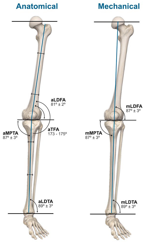
Physiological axes of the lower limb.
Notes. aLDFA, anatomic lateral distal femoral angle; aMPTA, anatomic medial proximal tibial angle; aTFA, anatomic tibiofemoral angle; aLDTA, anatomic lateral distal tibial angle; mLDFA, mechanical lateral distal femoral angle; mMPTA, mechanical medial proximal tibial angle; mLDTA, mechanical lateral distal tibial angle.
Anatomic axes of the femur and tibia
The anatomic axes of the femur and tibia are obtained from a line centred in the diaphysis of each bone. To determine the anatomic femoral axis, a line is drawn bisecting the femoral diaphysis into two parts. This line can be retrieved by joining two points in the middle of the medullar canal, one 10 cm above the knee joint and the other in the middle of the shaft, resulting in the distal anatomic femoral axis.5,6 The anatomic tibial axis bisects the tibial shaft, uniting two points, one proximally and other distally centred in the medullary canal. The anatomic femoral axis is not perpendicular to the axis of the tibia because of the deviation from the midline created by the femoral neck. Therefore, they form a physiological slight valgus angle.
Anatomic tibiofemoral angle
The anatomic tibiofemoral angle is measured between the anatomic axes of the femur and the tibia. This angle may be compared to the physiological value revealing the amount of deformity.7,8 The anatomical axes of the femoral and tibial diaphysis form a lateral angle of 173–175° (anatomic tibiofemoral angle/aTFA).
Mechanical axes of the femur and tibia
The femur and tibia mechanical axes are defined by the centre points of the hip, knee, and ankle joints. The femur mechanical axis is defined by a line from a point in the centre of the femoral head to a point in the centre of the knee. The femoral head centre is easily found by drawing several bisecting lines corresponding to the head circumference diameter. To find the centre of the knee, several points may be used. A commonly used point is the centre of the tibial spines. Alternatively, Moreland et al5 described a unique point on the knee that resulted from several measurements of different knee landmarks. Other authors define two different points for the centre of the knee. When drawing the mechanical axis of the femur, the distal point in the knee is marked in the centre of the femoral intercondylar notch. The centre of the tibial interspinous groove is then used as the starting point for the mechanical axis of the tibia. Using two different points at the knee brings some advantages: the identification of the tibial and femoral contributions to the deformity and the extent of the knee subluxation.1
The mechanical axis of the femur forms a physiological angle of 6° ± 1° with the anatomical femoral axis and is named the anatomical mechanical femoral angle (aMFA).9 The mechanical axis of the tibia is marked from the centre of the knee, previously assessed, and the centre of the talus or tibial plafond, defined using a ruler placed on the X-ray.1,7,8 The tibial mechanical and the anatomic axes are almost indistinguishable. Consequently, it is assumed that both lines run physiologically parallel to each other.
Mechanical tibiofemoral angle
To measure the mechanical tibiofemoral angle, a line corresponding to the mechanical axis of the femur is extended to form an angle with the tibial shaft axis. This angle is represented by a value that is then compared to the physiological angle and reveals the amount of the mechanical misalignment.
Mechanical axis of the lower limb
The mechanical axis of the lower limb, also called the Mikulicz line, is drawn by connecting a point in the centre of the femoral head to a point in the centre of the ankle. This line’s physiological position runs, on average, 4 ± 2 mm medial to the centre of the knee. Any deviation from this physiological range indicates either a valgus, if the line runs lateral, or a varus if it runs medially. The value of the deviation is measured in millimetres and is named mechanical axis deviation (MAD). The mechanical axis of the lower limb creates an approximate angle of 3° to the perpendicular axis of the body (Fig. 4).10
Fig. 4.

Normal mechanical axis of the lower limb.
Deformities of the lower limb
Deformities of the lower limb are defined as a deviation of the physiological axes in the frontal, sagittal or transverse planes and ultimately result in malalignment of the lower limb. Variations of the physiological longitudinal torque of the femoral and tibial diaphysis result in torsional deformities of the lower limb.
Frontal plane deformities
Most of the lower limb deformities occur in the frontal plane and are known as varus and valgus deviations. One frequent cause of secondary varus and valgus malalignment is the cartilaginous damage that results from a meniscectomy.10
In the presence of a frontal plane deformity, a non-physiological load distribution occurs in the knee’s medial or lateral compartment. The resulting mechanical overload originates progressive cartilage wearing and progressive degenerative disease. Osteotomies around the knee have a major impact on correcting the weight-bearing axis and the lower limb’s load distribution.
Regarding the indications, it is crucial to understand that, optimally, an osteotomy must be planned to correct the limb deformity on the bone and site where the deformity occurs. In this case, the osteotomy will restore the anatomy and mostly correct all joint angles and joint line obliquity (JLO) within the physiological range. It is crucial to keep in mind that an unplanned or poorly planned surgical procedure may dramatically change the joint line orientation with a catastrophic outcome.
The alignment of the limb can be drawn on an X-ray from the centre of the hip to the centre of the ankle. If this line runs roughly 4 ± 2 mm medial to the centre of the knee, the limb alignment is normal. When this is not the case, three questions must be answered: (1) how, (2) how much, and (3) where is the deformity?
Measurement of varus/valgus deformity
To assess the degree of a deformity, the mechanical tibiofemoral angle should be measured. A straight line is drawn from the centre of the femoral head to the centre of the knee (mechanical axis of the femur) and projected downward beyond the knee. The mechanical tibial axis, running parallel to the shaft of the tibia, is also drawn. The angle formed by the portion of the line projected beyond the knee and the tibial shaft axis is then evaluated. A measurement of about 0°/180° implies an average axis of the limb. Otherwise, the resulting tibiofemoral angle corresponds to the degree of the deformity.7,8
To characterize the deformity (answering the ‘how’ question), either the position of the foot or the mechanical axis of the limb (Mikulicz line) may be used. According to the position of the foot, a valgus is determined if the foot is lateral to the femoral axis and a varus if the foot is medial. When assessing the mechanical axis of the limb, a deviation from this physiological range designates either a valgus, if the line runs lateral, or a varus if the line runs medial.
In certain situations, including height, obesity, and radiograph quality, the visibility of the femoral head may be impaired. In these cases, the tibiofemoral angle may be assessed by calculating the anatomic femoral axis and assuming the anatomical mechanical femoral angle as 6°, so the difference is taken as the amount of deformity. In this case, the anatomic tibiofemoral angle is used instead of the mechanical angle and compared with the assumed standard value of 6° of valgus.9
In the case of an indistinct ankle joint, the tibial axis line should be drawn from the centre of the knee to a midpoint on the visible end of the tibia shaft.
Assessment of the deformity location
Axial deformities can result from an isolated deformity of the femur or tibia or combined deviations of the long bones. Double osteotomies of the femur and tibia allow the treatment of these complex deformities of the lower limbs, but they need careful surgical planning.
Due to the greater distance between the centre of the hip and knee joints than between the knee and ankle, the mechanical tibiofemoral axis runs slightly oblique, from craniolateral to mediocaudal, to the perpendicular axis of the body at an angle of approximately 3°.7,8
The tangent to the femoral condyles (knee baseline) and the tangent to the tibial plateaus, under physiological conditions, run almost parallel (joint line convergence angle = JLCA, 0–1 medial convergence).
The deformity underlying an axial malalignment is analysed by calculating the joint orientation angles by assessing orientation lines. Accordingly, the joint orientation angle is calculated between the line along either the mechanical or anatomical axis and the joint orientation line. A useful terminology for identifying the angles and axes was established by Paley11 based on the abbreviation of the joint and the orientation axis. The prefix a or m determines whether the angle is measured relative to the anatomical or mechanical axis, respectively. The second letter specifies whether the measured angle is lateral L or medial M to the selected axis line. The third letter designates whether the calculated angle is in proximal P or distal D joint. The fourth letter indicates if the angle has been measured for the tibia T or the femur F. Since the mechanical and anatomical axes of the tibia are expected to be parallel, the a and m prefix may be omitted in the tibia (Fig. 3).11
The physiological femoral joint angle (FJA) is 2–3° valgus to the femoral mechanical axis and 8–9° valgus to the femoral shaft axis. On the other hand, the physiological tibial joint angle (TJA) is 2–3° varus to the tibial mechanical axis.7,8
The result of the parallelism between the mechanical and anatomical axes of the tibia is that the anatomical and mechanical medial proximal tibial angle (aMPTA/mMPTA), between the tangent to the tibial plateau and the anatomical and mechanical axes, is 87 ± 3 in both cases. The anatomical and mechanical lateral distal tibial angle at the line of the ankle joint is 89 ± 3.10,11
Regarding the femur, the mechanical lateral distal femoral angle, calculated between the mechanical femoral axis and the baseline of the knee, is 87 ± 3. The knee baseline forms an angle of 81 ± 2 with the anatomical axis of the femur.10,11
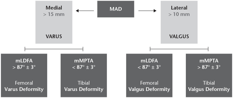
Malalignment in the frontal plane is analysed using the ‘malalignment test’ (Fig. 5) and is the result of the deviation of the mechanical axis.10,11 A clinically significant deviation in the frontal plane is identified when the mechanical tibiofemoral axis runs more than 10 mm lateral to the centre of the knee joint (valgus deviation) or more than 15 mm medial (varus deviation). The origin of the deformity can be femoral, tibial, or both. Thereby, to evaluate the individual contribution, we must assess the mechanical lateral distal femoral angle (mLDFA, standard value 87 ± 3) and the mechanical medial proximal tibial angle (mMPTA, standard value 87 ± 3).10,11 If the mLDFA is lower than the standard value, a femoral valgus deformity is found. On the other hand, if the mMPTA is increased concerning the standard value, a tibial valgus deformity is identified.
Fig. 5.
Evaluation of the deformity using the malalignment test.
Notes. MAD, mechanical axis deviation; mLDFA, mechanical lateral distal femoral angle; mMPTA, mechanical medial proximal tibial angle.
Regarding varus deformities, a femoral cause of varus malalignment is associated with an increased mLDFA and a tibial cause is associated with a lower mMPTA concerning the normal values.
In genu varum, the anatomic tibiofemoral angle (aTFA) is greater than 173–175°. The mechanical axis that runs from the centre of the femoral head to the centre of the ankle lays more than 4 ± 2 mm medial to the centre of the knee joint. In major varus deformities, the mechanical axis deviation (MAD) is over 15 mm medially (Fig. 6).10,11
Fig. 6.
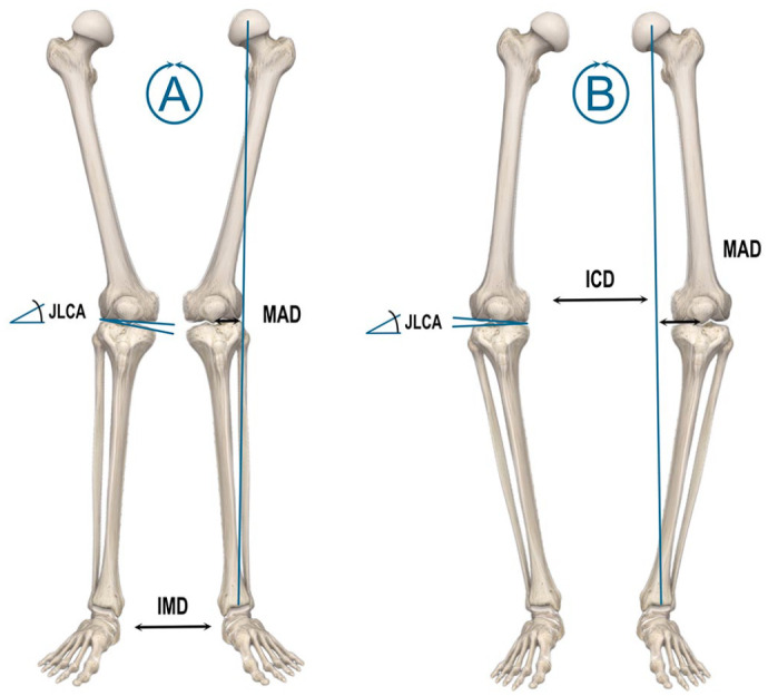
(A) Genu valgum: decreased anatomic tibiofemoral angle (aTFA < 173–175°). The weight-bearing axis runs lateral to the 4 mm point and the distance between the medial malleoli (intermalleolar distance = IMD) is increased. The angle between the tibial plateau and the tangent to the femoral condyles (joint line convergence angle: JLCA) is opened medially. (B) Genu varum: increased anatomic tibiofemoral angle (aTFA > 173–175°). The Mikulicz line runs medial to the 4 mm point (mechanical axis deviation: MAD > 15 mm medially) and the intercondylar distance (ICD) is increased. The joint forms an open angle laterally (JLCA).
The anatomic tibiofemoral angle (aTFA) in valgus deformities is less than 173°–175° and the Mikulicz line runs laterally from the point 4 ± 2 mm medial to the centre of the knee. A major valgus deviation of the mechanical axis is established when the line is more than 10 mm lateral to the joint centre (Fig. 6) (9,12).10,11
The joint line convergence angle (JLCA) is outlined by a line tangent to the femoral condyles and the tibial plateau. Under physiological conditions, the two lines are almost parallel to each other (0–1 medial convergence). The JLCA is opened medially on valgus knees and laterally on the varus.10,11
Extra-articular deformities
Occasionally, the limb deformity arises in the context of a significant extra-articular deformity. In the previous topic, the deformity was assessed by estimating the mechanical or anatomical joint angle of the femur and the tibia, ignoring the intermediate shape of the respective tibial and femoral diaphysis. However, in the case of significant extra-articular deformity (secondary to fracture or development abnormalities), the total contribution of the extra-articular deformity for the limb misalignment must be identified.
The evaluation of extra-articular deformities or mixed articular and extra-articular deformities can be carried out using computer programs, tracing paper, or even basic trigonometry. When assessing the contribution of an extra-articular deformity to the limb deformity, the extra-articular approximation theorem proposed by Krackow8 may be used. According to this theorem, ‘a tibial or femoral shaft extra-articular deformity of a certain angular amount creates a corresponding deformity at the knee in approximate proportion to the percentage of the way that deformity is located toward the knee’.8 Consequently, the closer an extra-articular deformity is to the knee, the greater the influence of that deformity at the joint (Fig. 7).
Fig. 7.
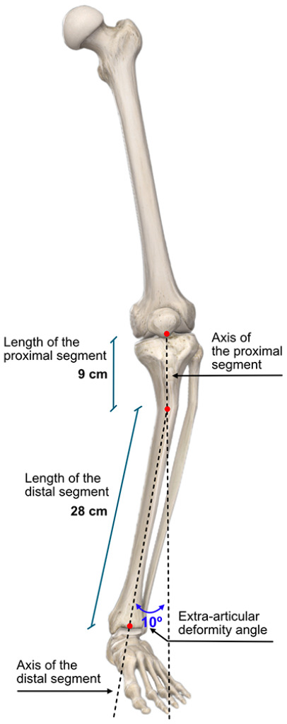
Example of assessing the contribution of an extra-articular deformity to the limb deformity: the angulation at the extra-articular deformity is 10°. The proportional distance from the ankle to the knee is calculated as follows: ²⁸⁄(₂₈+₉) = ²⁸⁄₃₇ = 75.7%; therefore, 75.7% of 10° equals 7.6°. So, the contribution of extra-articular angulation to the overall knee alignment is about 7.6°
Rotational deformities
Congenital torsion deformities of the lower limb may result from growth disorders of the acetabulum, femur, tibia, or foot. In these cases, rotational deformities of the femur may originate a pathological compensatory overcorrection of the tibia that results in a rotational composite deformity of the lower limb at several levels. Consequently, congenital torsion deformities should be differentiated from posttraumatic rotational deformities as they are addressed differently.10
The term torsion designates the rotation of a bone segment in the longitudinal axis of long bones. In return, the concept of rotation indicates the rotational position between two bones at the joint level and is related to the joint motion (e.g. internal rotation of the hip). The torsion angle is then defined as the angle between the distal joint axis and the proximal joint axis in the transverse plane (internal and external rotation). A CT scan is indicated to obtain the most precise values by overlaying the projections of the articular axes.10
A pathological torsion angle is present if the attained angle differs more than two standard deviations from the physiological value. For routine clinical assessments, the normal range is from 0° to 40°. Larger angles and negative angles are abnormal. We can also use side-to-side comparison as reported by Jend et al where a difference of more than 8° should be considered abnormal.10
Congenital torsion deformities can produce significant disabilities of the lower limbs from coxarthrosis to patellar instability and patellofemoral cartilage degeneration.
Femoral torsion angle
The torsion angle of the femur is defined by the angle between the projection of the line that runs, in the transverse plane, from the centre of the femoral head through the centre of the femoral neck and the tangent line to the posterior femoral condyles (Fig. 8).10 The femoral neck is physiologically positioned in external rotation concerning the distal segment of the femoral shaft, defining the antetorsion angle. The torsion angle of the femur is measured between the distal femoral condyles and the femoral neck in adults and is usually 15.6 ± 6.7°.10
Fig. 8.
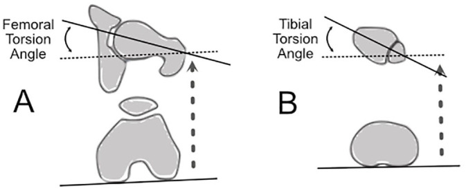
(A) Femoral torsion angle. The angle between the femoral head–neck axis in the transverse plane and the tangent line to the posterior femoral condyles. (B) Tibial torsion angle. The angle between the posterior tangents at the proximal tibial condyles and the central distal transmalleolar axis.
Torsional deformities of the femur may be related to progressive retropatellar cartilage damage and degeneration secondary to augmented patellar contact pressure and instability of the patella due to patellofemoral malalignment.10
Tibial torsion angle
The angle between the posterior tangents at the proximal tibial condyles and the central distal transmalleolar axis with the lower limb in neutral position is designated tibial torsion angle. The physiological value at the end of growth for the tibial external torsion angle ranges from 23.5 ± 5.1° (TT) (Fig. 8).10
Imaging assessment of torsion deformities
Radiological evaluation of torsion deformities includes conventional X-rays of the femur and tibia in anteroposterior and mediolateral planes. For the assessment of torsion deformities of the proximal femur and acetabulum, a pelvic X-ray is needed to evaluate the Wiberg angle and the femoral inclination angle. Although mathematical formulae can be used to assess femoral and tibial torsion angles from conventional X-rays, CT scan makes this evaluation much more effortless.10
The assessment of the patellofemoral joint alignment with measurement of the Tibial tubercle-trochlear groove distance (TT-TG) is done with scans at the lowest point of the trochlea and the most anterior point of the tibial tuberosity. The TT-TG distance is measured between the lines that cross these points and run perpendicular to the tangent at the posterior condyles and the standard value is 10–15 mm.10 Femoral and tibial torsion measurements obtained with 3D models based on biplanar radiographs are interchangeable with standard CT measurements in patients with osteoarthritis of the knee.4
Footnotes
ICMJE Conflict of interest statement: NML declares no conflict of interest relevant to this work.
RV declares consultancy for Stryker, expert testimony for DePuy, payment for lectures including service on speakers bureaus from DePuy and Stryker, and payment for development of educational presentations from DePuy, all outside the submitted work.
OA licence text: This article is distributed under the terms of the Creative Commons Attribution-Non Commercial 4.0 International (CC BY-NC 4.0) licence (https://creativecommons.org/licenses/by-nc/4.0/) which permits non-commercial use, reproduction and distribution of the work without further permission provided the original work is attributed.
Funding statement
No benefits in any form have been received or will be received from a commercial party related directly or indirectly to the subject of this article.
References
- 1. Sheehy L. Radiographic assessment of leg alignment and grading of knee osteoarthritis: a critical review. World J Rheumatol 2015;5:69. [Google Scholar]
- 2. Zampogna B, Vasta S, Amendola A, et al. Assessing lower limb alignment: comparison of standard knee Xray vs long leg view. Iowa Orthop J 2015;35:49–54. [PMC free article] [PubMed] [Google Scholar]
- 3. Sheehy L, Felson D, Zhang Y, et al. Does measurement of the anatomic axis consistently predict hip-knee-ankle angle (HKA) for knee alignment studies in osteoarthritis? Analysis of long limb radiographs from the multicenter osteoarthritis (MOST) study. Osteoarthritis Cartilage 2011;19:58–64. [DOI] [PMC free article] [PubMed] [Google Scholar]
- 4. Buck FM, Guggenberger R, Koch PP, Pfirrmann CWA. Femoral and tibial torsion measurements with 3D models based on low-dose biplanar radiographs in comparison with standard CT measurements. AJR Am J Roentgenol 2012;199:W607–W612. [DOI] [PubMed] [Google Scholar]
- 5. Moreland JR, Bassett LW, Hanker GJ. Radiographic analysis of the axial alignment of the lower extremity. J Bone Joint Surg Am 1987;69:745–749. [PubMed] [Google Scholar]
- 6. Yoshioka Y, Siu D, Cooke TD. The anatomy and functional axes of the femur. J Bone Joint Surg Am 1987;69:873–880. [PubMed] [Google Scholar]
- 7. Krackow K. The measurement and analysis of axial deformity at the knee. Mahwah, NJ: Homer Stryker Center, 2008. [Google Scholar]
- 8. Krackow K. Preoperative assessment: axial and rotational alignment an X-ray analysis. In: Krackow K, The technique of total knee arthroplasty. St. Louis: The CV Mosby Company, 1990. [Google Scholar]
- 9. Chao EY, Neluheni EV, Hsu RW, Paley D. Biomechanics of malalignment. Orthop Clin North Am 1994;25:379–386. [PubMed] [Google Scholar]
- 10. Lobenhoffer P, van Heerwaarden R, Staubli A, Jakob R, Galla M, Agneskirchner J. Osteotomies around the knee, indications - planning - surgical techniques using plate fixators. Davos: Switzerland: AO Publishing, Thieme Verlag, 2008. [Google Scholar]
- 11. Paley D. Radiographic assessment of lower limb deformities. In: Paley D, Principles of deformity correction. Berlin Heidelberg: Springer, 2002:31–60. [Google Scholar]


