Abstract
Background
Single photon emission computed tomography (SPECT) is an important functional tool for clinical diagnosis and scientific research of brain disorders, but suffers from limited spatial resolution and high noise due to hardware design and imaging physics. The present study is to develop a deep learning technique for SPECT image reconstruction that directly converts raw projection data to image with high resolution and low noise, while an efficient training method specifically applicable to medical image reconstruction is presented.
Methods
A custom software was developed to generate 20,000 2-D brain phantoms, of which 16,000 were used to train the neural network, 2,000 for validation, and the final 2,000 for testing. To reduce development difficulty, a two-step training strategy for network design was adopted. We first compressed full-size activity image (128×128 pixels) to a one-D vector consisting of 256×1 pixels, accomplished by an autoencoder (AE) consisting of an encoder and a decoder. The vector is a good representation of the full-size image in a lower-dimensional space and was used as a compact label to develop the second network that maps between the projection-data domain and the vector domain. Since the label had 256 pixels only, the second network was compact and easy to converge. The second network, when successfully developed, was connected to the decoder (a portion of AE) to decompress the vector to a regular 128×128 image. Therefore, a complex network was essentially divided into two compact neural networks trained separately in sequence but eventually connectable.
Results
A total of 2,000 test examples, a synthetic brain phantom, and de-identified patient data were used to validate SPECTnet. Results obtained from SPECTnet were compared with those obtained from our clinic OS-EM method. Images with lower noise and more accurate information in the uptake areas were obtained by SPECTnet.
Conclusions
The challenge of developing a complex deep neural network is reduced by training two separate compact connectable networks. The combination of the two networks forms the full version of SPECTnet. Results show that the developed neural network can produce more accurate SPECT images.
Keywords: Deep learning, convolutional neural network, SPECT, image reconstruction, quantitative imaging
Introduction
Single-photon emission computed tomography (SPECT) is a functional nuclear medicine imaging technique that is commonly used in clinic. It is used for diagnosis and monitoring of many diseases and organ functions, such as cardiac vascular diseases (1), tumor (2), and brain functions (3). It is also useful for dosimetry of radionuclide targeted therapies (4). However, SPECT images are known to suffer from limited spatial resolution (1–2 cm full-width half maximum) and high noise. These limitations are inherent to the current clinical SPECT systems due to the hardware design, mainly the collimator. The resulting projection data is thus blurred and contains high noise, creating a very ill-posed inverse problem with large null space for image reconstruction.
There have been many reconstruction algorithms developed for SPECT trying to tackle those issues. The most successful ones are statistical iterative reconstruction algorithms such as maximization likelihood expectation maximization (ML-EM) (5-7), ordered subset expectation maximization (OS-EM) (8,9), and maximum a posteriori (MAP) (10-12). Models of physics can also be incorporated into these algorithms to compensate for the attenuation, resolution, and scatter. However, the improvement in resolution is far from ideal due to unrecoverable losses of information to the null space. In addition, even though resolution improves with increasing numbers of iteration, noise in the image also increases. The reconstruction also introduces correlation to the noise that is usually difficulty to quantify, and sometimes may result in false detection. There have also been efforts to develop new generation of SPECT systems that can provide high sensitivity and better spatial resolution. However, those systems are usually expensive or organ specific, such as dedicated cardiac SPECT or brain SPECT systems (13). Their adoption in clinic is slow and limited. Therefore, it is highly desirable to develop a reconstruction method for current SPECT systems that can provide high spatial resolution but low noise.
Inspired by recent achievements of deep learning-based reconstruction in magnetic resonance imaging (MRI) (14-17) and X-ray computed tomography (CT) imaging (18-21), researchers have attempted applying deep learning to positron emission tomography (PET) imaging (22-24), but the application to SPECT is not reported yet. To approximate the nonlinearity in reconstructions in medical imaging, these deep neural networks (DNN) often comprise of many layers. In 2018, Wang et al. compared the performance of neural networks applied to CT imaging using 90–150 convolutional layers (a three-layer convolutional core is repeated by 30–50 times) (25). As expected, more layers provide better results because of better approaching the ideal (analytic) solution. But complex network architecture increases the training difficulty, especially training learnable parameters in the deep layers. When the output of the network is a large image with many voxels, training is more stressful due to the large-dimension space, resulting in slow convergence or even no convergence at all.
In this paper, an image-reconstruction neural network, termed SPECTnet that learns to directly map between the SPECT projection-data domain and the activity-image domain, is presented. The input of the neural network consists of two channels: projection data, and attenuation map obtained from a CT transmission scan. The output of the network system is the reconstructed activity image with high-resolution and low noise. Instead of designing a neural network mapping between the scanned-signal domain and reconstruction image domain directly, we propose a training strategy consisting of two separate procedures, which can efficiently train DNNs for medical imaging, including but not limited to SPECT image reconstruction. The two stages are: first, a neural network developed to translate the projection data to small (compressed) images—in fact, a 1-D vector; then the second network responsible to up-sample (decompress) the small image to full (128 by 128) image. As far as the training process is concerned, the sequence is reversed: we need to find the compressed version (256×1 pixels) of the full-size activity image at first, which is accomplished by developing a sparse autoencoder (AE), composed of an encoder and a decoder. The compressed vector can be thought of as a compact representation of the full-size image in a lower dimensional space. Then, we develop a neural network mapping between the projection-data domain and the compressed-vector domain. Since there are fewer outputs (256×1 pixels) for the network to solve now, this neural network can be compact and converges easily. The neural network is followed by the decoder (a portion of the AE) that is developed in the first step, to decompress the 1-D vector to a full-size image. We believe the proposed network-training approach is applicable to all DNN-based image-reconstruction modalities, such as CT, MRI, PET, and SPECT imaging, to ease the stress of design.
The size of SPECTnet is compact, with only seven convolutional layers and two fully-connected layers in total. As a comparison, most of the existing medical image reconstruction neural networks consist of tens or hundreds of layers (14-25). SPECTnet was trained by simplified phantom with simulated SPECT data, and validated by a synthetic brain phantom with simulated SPECT data and patient data. Results were compared with images reconstructed by an OS-EM algorithm. Although 2-D image reconstruction is discussed in this paper only, the present method will be helpful and heuristic to design complex neural networks for 3-D medical image reconstruction. We present the following article in accordance with the TRIPOD reporting checklist (available at http://dx.doi.org/10.21037/atm-20-3345).
Methods
The study was conducted in accordance with the Declaration of Helsinki (as revised in 2013). This study was approved by the Johns Hopkins Institutional Review Boards (IRB protocol number: IRB00100575). No information consent was required since de-identified pre-existing patient data were used.
Phantoms and data acquisition
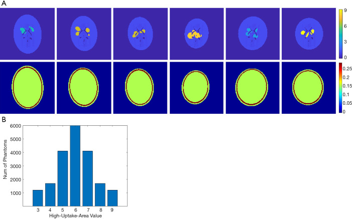
Designing a neural network for medical imaging requires ground-truth data (precise images) to support the training, but which is unknown/unavailable in practice. Existing deep-learning approaches often use reconstructed images from conventional methods as the label (target) to train the neural network (22,23). Therefore, the image quality is impossible to surpass the conventional approach. On the other hand, usually only a few tens of patient data were employed to train the neural network for medical imaging. Such a small data pool would highly likely make the neural network overfit the training data. To avoid overfitting, we developed software that can randomly generate simplified 2-D digital phantoms. With this software, we produced 20,000 2-D phantoms. Each phantom contains a pair of images: an activity image and the corresponding attenuation map. Each phantom is unique in the database. Example phantom images generated by the software are presented in Figure 1A. All images are 128 by 128 pixels with a 2 mm by 2 mm pixel size. The activity images consist of an elliptical low-uptake background area, and a few high-uptake regions with random shapes and locations inside the background. The activity values ranged from 3 to 9 for the high-uptake region and were kept at 1 for the background. Activities outside the background were set to zero. Phantoms with high-uptake area values assigned to 6 are the most cases in our database, and the number of phantoms reduces when the assigned value becomes larger or smaller (complies with a Gaussian distribution), as summarized in Figure 1B. These activity images were used as ground truth in the subsequent neural network training. Corresponding attenuation map for each phantom was generated with attenuation coefficient of water assigned inside the elliptical background. A ring of 2–4 mm thick bone structure was also added outside the background to mimic attenuation of a skull in brain imaging. Despite the simplicity of these phantoms, we believe they are sufficient for network development specifically for the SPECT brain functional imaging, which were validated as will be described in the Results section of this paper.
Figure 1.
Training data and statistics. (A) Generated random 2-D head phantoms by custom software. The first row shows the activity images. The high-uptake area is assigned to 3–9 and the rest area in the head is assigned to one. The background is zero. The second row shows the attenuation map image corresponding to the first row. (B) The number of phantoms meets standard normal distribution according to the assigned values of the high-uptake area in the activity image. Assigned value equal to 6 is the most cases in the database.
These phantoms were used to generate projection data through an analytical simulation with models of attenuation and limited spatial resolution (26). The spatial resolution was modelled using spatially varying Gaussian functions that were calculated based on LEHR collimators (27). A total of 120 projection views over 360° were simulated with 128 bins, resulting in a 120×128 sinogram array. Considering the first few rows and the last few rows in the sinogram are from physically neighboured angles of view, we padded sinogram to a 128×128 matrix by replicating the first 8 rows of data behind the last row of the sinogram. This allows the 2-D filter of the convolutional layer to have the opportunity to consider the neighbouring angles that are contiguous in space but were otherwise disconnected in the original sinogram. The 20,000 phantoms and their corresponding projection data were split into three groups: 16,000 were randomly selected out for training the neural network, another 2,000 were selected for validation, and the final 2,000 for testing. In addition, de-identified patient data, including the synthetic patient phantom and de-identified clinic data were used to test the developed neural network.
Algorithm design
Developing a neural network architecture that directly maps the projection-data domain to the image domain is challenging. The essential reason lies in the complex nonlinearity between the two domains, which requires a powerful network having many layers to approximate. However, DNNs are difficult to train, especially in the deep layers, where the learnable parameters suffer from an extremely slow learning speed. The desire to output a large image from the network makes the convergence even slower. Hence, we developed the neural network only reconstructing compressed image from measurement data. The up-sampling to a full-size (128×128) image is accomplished by another neural network. Thus, the flow chart is: projection data domain → compressed vector domain → full-size image domain.
The compressed image domain (each compressed image consisting of 256×1 pixels) is like a bridge to connect the projection-data domain and the full-size image domain, which is for the purpose of easing the neural network training. From the training point of view, the compressed images work as the label to design the first neural network. As a result, mapping between the projection-data domain and the compressed-image domain only requires a compact neural network, because of fewer unknowns to be solved (256 pixels). Its training is less challenging benefiting from the compact architecture.
Nevertheless, the critical issue is to find a compressed-vector representation that uniquely maps to a regular size image in the decompressed image domain. In our method, this is accomplished by an AE. The AE is composed of an encoder that learns a compressed representation of the input image, and a decoder that uses the learned compressed representation to reconstruct the input at its output. The output of the encoder (which is the input of the decoder) usually has smaller size than its input. A typical form of the AE is illustrated in Figure 2. Assuming the input is an image XM having M pixels, the wide-in-narrow-out structure of the encoder allows it to compress the input to fewer pixels YN,
Figure 2.
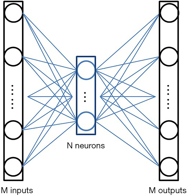
Typical architecture of an AE. Each input and output stands for a pixel in the image. The intermediate N elements are the output of the encoder, also are the input of the decoder. Usually, M>N.
| [1] |
and the narrow-in-wide-out structure of the decoder recovers the M pixels from the compressed image:
| [2] |
where M>N. The AE tries to recover the input at its output, i.e.,. Therefore, the AE is an unsupervised learning approach as it uses the same image as the input (to the encoder) and output (of the decoder). No additional labels are required during the training.
Once such an AE was successfully developed, we had the brain activity images (full-size images) pass the encoder. The output of the encoder, having fewer pixels, can be viewed as a compact representation of the regular image in a lower-dimensional space. These compact representations were employed as the label to design the neural network translating the SPECT signals to compact representations (1-D vectors).
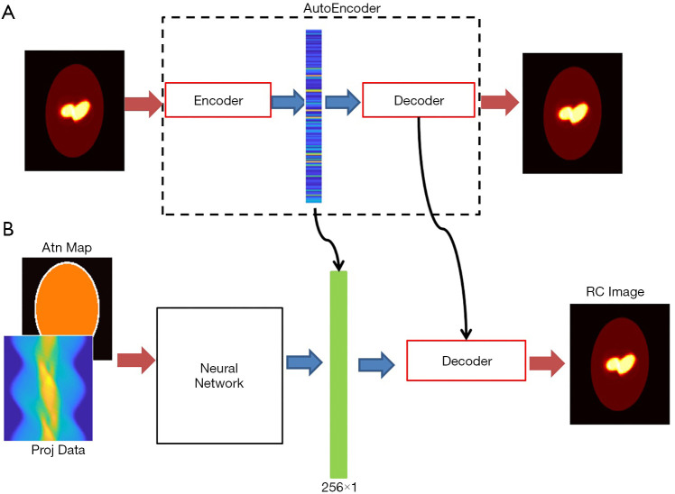
The full view of our design scheme is illustrated in Figure 3A is a prototype of the AE, whose input and output are both 128×128 images, with the middle layer producing the compressed vector in form of 256×1 pixels. The compressed 1-D vectors were then used as the label to train the neural network in Figure 3B, whose task was to convert the measurement data into the compressed vectors. The neural network has two input channels accepting the projection data and the attenuation map, respectively. The neural network was followed by the decoder (developed in the AE training session) to decompress the compressed vector to a regular image.
Figure 3.
The overall scheme of SPECTnet. (A) An AE aims to recover the input image at its output; (B) complete SPECTnet whose decoder is carried from the AE.
Network architecture
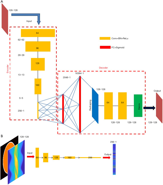
Motivated by the capability of 2-D convolution in extracting features from 2-D images, we developed an AE which compresses and decompresses 2-D images, with its architecture shown in Figure 4A. The encoder is composed of five convolutional layers, which accepts a 128×128 image and converts it to a compressed vector in 256×1 pixels. Each convolutional layer is followed by a rectified linear unit (ReLU) convert function and a batch-normalization layer. The stride is 2 in the first four convolutional layers and 1 in the fifth layer. No padding was used. We used stride =2 instead of using a max pooling for down-sampling because we believe the latter would lose information. The filter size is 6×6 in the first two layers and 5×5 in the next three layers. The number of filters and the size of the output image in each layer have been illustrated in Figure 4A. Note that the fifth layer employs 256 filters, so it converts the input 5×5 images into 256 1×1 images, i.e., a 256×1 output. The decoder starts with two fully-connected layers, with 2,048 neurons in the first layer and 16,384 in the second, respectively, and each is followed by a sigmoid function. Then a reshaping layer is applied to reshape the 16,384 pixels to 128×128. In our design, instead of transposed convolution, we employed two fully-connected layers for up-sampling trading-off efficiency. The transposed convolution would have five layers if symmetric to the down-sampling. Next, two convolutional layers are added to optimize the reshaped image, and a deconvolution was finally applied to present a 128×128 image.
Figure 4.
Details about the artificial neural networks. (A) Architecture of the AE. The number of filters in each convolutional layer is dis-played in the blocks. The filter size is 6×6 for the first two layers, and 5×5 for the last three layers in the encoder; and 3×3 in the decoder. Stride in the first four layers of the encoder is 2, and 1 elsewhere. (B) Architecture of the neural network accepting SPECT projection data and attenuation map, both in form of 128×128 matrix. The output of the network is the compressed image having 256×1 pixels.
The neural network converting measurement data to compressed vector adopts the similar architecture to the encoder (Figure 4B). If using other architectures, one must assure that the output dimension matches the input of the decoder. Also notably, the input layer of the data-to-vector neural network has two channels to accept the projection data and the attenuation map, respectively, which is different than the encoder’s input layer (one input channel only).
Network training
As mentioned earlier, the AE has to be trained first in order to find the compressed representation. We randomly selected 16,000 activity images from the phantom database to train the AE, and another 2,000 images to perform validation after each epoch during the training.
The cost function employed in training was a common mean-squared-error function, and the training algorithm was Adam (28). The minibatch size was set to 160, thus each epoch contained 100 iterations to fully use the 16,000 training data. The initial learning rate was set to 1×10⁻⁴ and the optimal L2 regularization parameter was found to be 0.08 after a few trials. Fifty epochs were applied to achieve an acceptable performance within 47 minutes on an Intel workstation equipped with two NVidia Quadro P6000 GPUs and 128 GB memory.
The filters in each layer were investigated when the training was complete. Figure 5 presents the 64 filters in the first convolutional layer. As can be seen, each filter had learned a specific transferring rule after the training. One might need to increase the number of filters if each filter contains intensive pixel variation, and must reduce the number of filters if there are filters found to not contain valuable information (for example, parameters are all zero). Usually, insufficient number of filters does not present the best performance, but too many filters cause extra unnecessary burden of computation. By inspecting the filters in each layer, one may find the appropriate number of filters for each layer.
Figure 5.
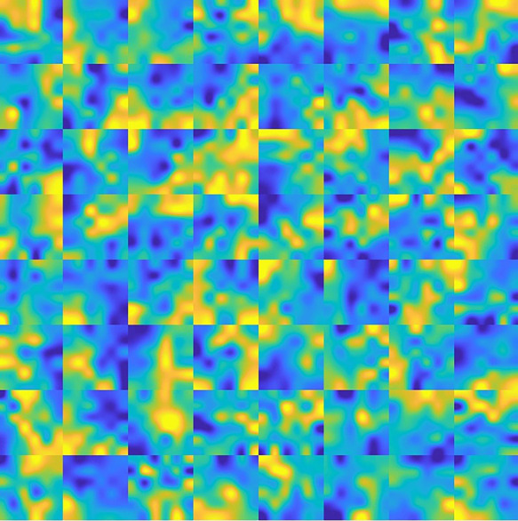
The 64 filters employed in the first layer of AE. Each filter is a 6 by 6 matrix.
Figure 6 presents an original image, and the recovered image by the AE. It can be found that the recovered image was not strictly identical to the original one, due to loss during compression. For the 2,000 validation images, the mean square error (MSE) between the original image and the recovered image is by average 0.076, with standard deviation 0.025. As far as SPECT imaging is concerned, such quality degradation is acceptable because SPECT reconstruction images are usually far worse in practice (i.e., in regards to the image error relative to the ground truth).
Figure 6.
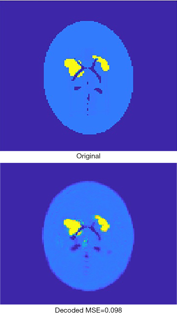
The original image is compressed to 256 pixels and then recovered by the decoder. The recovered image is a lossy image with respect to the original image.
The encoder was extracted from the AE when it had been fully trained, and then the 16,000 activity images selected to train the AE were given to the encoder to generate corresponding compressed vectors. The same was done for the 2,000 images to be used for validation. These compressed 1-D vectors were used as labels for developing the next neural network, whose inputs were corresponding projection data and attenuation-map images.
The algorithm for training the neural network was still Adam. As shown in Figure 7, the training converged very quickly, terminated at 20 epochs, which required only 6 minutes on the same workstation. The root MSE (RMSE) for the 2,000 validation cases was tracked during the training and illustrated in Figure 7.
Figure 7.
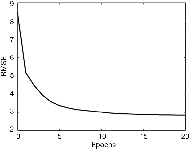
The progress when training the neural network converting projection data and attenuation map to compressed image. The RMSE reduced very quickly and saturated when the training reached around 20 epochs. Data shown in this plot are the 2,000 cases for the validation purpose.
Next, we combined the neural network and the decoder to form the complete version of SPECTnet to reconstruct SPECT images given projection data and an attenuation map. The total size of SPECTnet is only 127 Megabytes. To further optimize SPECTnet, we have used the projection data and attenuation map as the input, and the 128×128 activity image as the output to fine-tune the network, still with the 16,000 training datasets. After running 19 epochs that spent 18 minutes on the same workstation, the performance tended to saturate. The MSE was further reduced by 7 percent on average for the 2,000 validation cases in comparison to SPECTnet without fine-tuning.
Statistical analysis
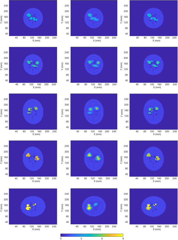
The 2,000 test data isolated from the 16,000 training data and the 2,000 validation data were employed to evaluate SPECTnet. Example reconstructed images by the developed network using the test data are presented in Figure 8. The first column shows the ground-truth image, with different assigned values for the high-uptake area. The second column shows the images reconstructed using an OS-EM algorithm with compensations for attenuation and resolution blurring. Reconstructions were performed on a Linux cluster, and appropriate number of iterations was individually applied to each case when the lowest MSE was achieved (12 subsets, 5–15 iterations took approximately 5–16 seconds). The third column presents the reconstructed images by SPECTnet. Each image was obtained in less than one second. The images generated by SPECTnet have sharp edges and better spatial resolution and contrast than those from the OS-EM reconstruction. There were also no ringing artifacts in SPECTnet generated images as compared with OS-EM results.
Figure 8.
Five cases and their reconstructed images with different value in the high-uptake area (low to high from row 1–5). The first column shows the ground truth. The second column is the OS-EM reconstruction. The third column is the SPECTnet reconstruction.
To quantitatively compare the images reconstructed by SPECTnet and OS-EM, we calculated the average activity concentration in the high-uptake area and low-uptake background area, respectively, as well as the SD, for images presented in Figure 8. The calculated values are presented in Table 1. Cases 1–5 correspond to the images shown in Rows 1–5 in Figure 8. The high-uptake-area-to-background activity concentration ratio increased from 4 to 9 from Case 1 to 5. The average activity concentration values in the SPECTnet images are closer to the exact values than those in the OS-EM images for both high-uptake and low-uptake region, in all five cases. In addition, we also used the following equation to calculate the mean error between the reconstructed image and the ground-truth image for the 2,000 test examples.
Table 1. Numerical comparison between SPECTnet and OS-EM for Figure 8 in the uptake regions by activity mean value and SD.
| Case | High-uptake region mean activity (SD) | Low-uptake background mean activity (SD) | ||||
|---|---|---|---|---|---|---|
| True | SPECTnet | OS-EM | SPECTnet | OS-EM | ||
| 1 | 4 | 3.52 (0.83) | 3.27 (0.87) | 1.01 (0.19) | 1.01 (0.27) | |
| 2 | 5 | 4.43 (0.98) | 3.93 (1.22) | 1.01 (0.30) | 1.03 (0.32) | |
| 3 | 6 | 5.32 (0.99) | 4.16 (1.53) | 1.00 (0.29) | 1.03 (0.32) | |
| 4 | 7 | 6.23 (1.16) | 5.69 (1.72) | 0.99 (0.30) | 1.03 (0.39) | |
| 5 | 9 | 8.19 (1.34) | 7.32 (2.37) | 1.04 (0.31) | 1.05 (0.44) | |
| [3] |
Note that only the uptake area was considered for this calculation. For the high-uptake area, the mean error in the SPECTnet images was by average 0.68, which is significantly smaller than that in the OS-EM images with a value of 1.72; for the low-uptake area, the mean error in the SPECTnet images was 0.04, on average, also very comparable to the counterpart (0.10) in the OS-EM images.
Results and comparisons
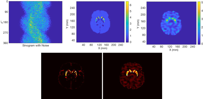
We tested the SPECTnet performance using simulated data from the Zubal brain phantom (29) with a striatum to background activity concentration ratio of 6:1. The SPECT data were generated using the same analytical projection method described earlier. Figure 9 shows the phantom activity image, and the reconstructed image by SPECTnet as the SPECT data and attenuation map were fed to the input channel, and OS-EM (50 iterations were used to achieve the best result for the Zubal phantom, other parameters are the same as earlier). As expected, SPECTnet accurately reconstructed the shape and activities of the striatum and background, and the result was very close to the truth. On the other hand, the OS-EM result was blurred and had ringing artifacts. Some concave characteristics on the edge of the brain were not well reconstructed by SPECTnet. The reason was that the background activities in the training data of SPECTnet were all convex shaped. We expect performance will be improved when more realistic phantoms are used in our future training database.
Figure 9.
Zubal phantom and the reconstruction by SPECTnet. (A) is the ground truth, (B) shows reconstruction by SPECTnet, and (C) is the reconstruction by OS-EM.
Figure 10 presents the reconstruction results when the projection data contains noise that matched the levels seen in clinic. The results from two methods are shown in the first row of Figure 10, where the sinogram with noise is also displayed. As expected, image quality is degraded from the noise-free case. The noise in OS-EM image was high and correlated. The image achieved by SPECTnet contains much less noise and continues to present accurate shape and uptake within the striatum. Their image error to the ground truth, executed by a direct subtraction, is presented in the second row of Figure 10. Relevant statistical values for Figures 9 and 10 are provided in Table 2. The average activity concentration values provided by SPECTnet are found to be more accurate than those by OS-EM, and the errors are also smaller than OS-EM.
Figure 10.
Up-left is the Sinogram with noise; up-central is the reconstruction by SPECTnet; up-right is the reconstructed image by OS-EM. The bottom row shows the error image by SPECTnet (left) and OS-EM (right) respectively to the ground truth.
Table 2. Numerical comparison between SPECTnet and OS-EM for Zubal brain phantom imaging in the uptake regions.
| Case | High-uptake region mean activity (SD) | Low-uptake background mean activity (SD) | ||||
|---|---|---|---|---|---|---|
| True | SPECTnet | OS-EM | SPECTnet | OS-EM | ||
| Noise-free | 6 | 5.35 (0.89) | 3.71 (1.14) | 1.00 (0.16) | 0.99 (0.34) | |
| Noise | 6 | 4.04 (0.93) | 3.18 (1.03) | 0.98 (0.12) | 0.98 (0.50) | |
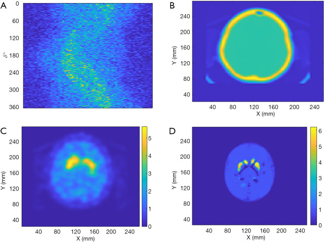
Finally, de-identified data from a patient collected by a Symbia T16 SPECT/CT system (Siemens Healthineers, Erlangen, Germany) was used to test the performance of SPECTnet. The patient data had pixel size of 3.895 mm which was linearly interpolated to 2 mm to match the input-data size of SPECTnet. The sinogram as shown in Figure 11A is very noisy and contains significant scatter. The attenuation map obtained from the CT scan is shown in Figure 11B. The patient sinogram and attenuation map were used to reconstruct an image by OS-EM with post-reconstruction filtering and compensation for attenuation and resolution, and the result is shown in Figure 11C. The patient data were also reconstructed by SPECTnet and the result is shown in Figure 11D. The image obtained by SPECTnet demonstrated less noise and had more uniform background uptake than that created by OS-EM with filtering. Since the ground truth is unknown, we were not able to quantitatively compare the results from the two methods.
Figure 11.
Reconstruction using patient data. (A) Patient sinogram; (B) attenuation map; (C) reconstructed image by OS-EM with post-reconstruction filtering; (D) reconstruction by SPECTnet.
Discussion
The developed SPECTnet can accept projection data to produce activity images directly. Compared to published work using conventional approaches to produce a raw image and then using a neural network to optimize (30), SPECTnet is more convenient and more efficient (produces an image in less than a second), especially when compared to those involving iterative algorithms and a large number of training data required to be pre-reconstructed. However, since the network was trained by simple phantom geometry (all elliptical), all reconstructed brains have an ellipse shape (Figure 9B and Figure 11D) which means detailed characteristics of the profile were lost. Therefore, more practical head profiles will be taken in our future study.
Since SPECT data usually contain more considerable noise and scatter, the neural network development for SPECT image reconstruction might be more challenging than those developed for PET reconstruction (22-24). To reduce the training difficulty, we present the two-step training strategy in this paper. But to shed a light on the challenge of training, we used the same network architecture as SPECTnet and the same data to retrain the network, but with an end-to-end (one step) direct training strategy, such that we can compare the convergence efficiency with what presented in Section 2. Again, we used 16,000 data pairs for training and 2,000 data pairs to validate. The minibatch size was set to 160 still. The training progress is presented in Figure 12, in which both RMSE and the loss reduction are illustrated. As can be seen, the convergence speed was very slow. Even when 300 epochs elapsed (30,000 iterations) which took 5 hours on the GPU, the network still could not produce meaningful images. When the organs to be imaged are more complex, the direct end-to-end training strategy might be unable to converge at all. Even if a solution could eventually be found, the entire development would be very challenging.
Figure 12.
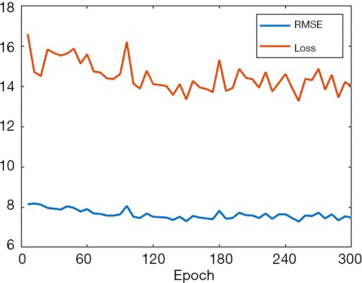
The training progress represented by RMSE and loss when the end-to-end direct training method was applied.
Conclusions
We have developed a DNN that successfully reconstructs 2-D images from SPECT projection data and an attenuation map. To reduce the difficulty in training such a neural network, we first developed an AE whose task was to find the compressed image of large activity images. These compressed images were used to design a compact neural network mapping between the signal domain and the (compressed) image domain. After the compact neural network was successfully trained, it was then connected with the decoder to decompress the small image into a regular activity image. Our results show that the present method can efficiently design DNNs for image reconstruction. By following the present method, the developed SPECTnet can provide more accurate 2-D images than a conventional OS-EM algorithm. Although the full architecture of SPECTnet for 2-D imaging is not complex, the proposed method will be very helpful to design a much deeper network for 3-D reconstruction, which is the next step of our research.
Many existing neural networks developed for nuclear image reconstruction were trained by only a few tens of patient data, resulting in the high likelihood of overfitting to the data used in training. Hence, we developed software to produce virtual 2-D digital brain phantoms to enrich the dataset pool, with high-uptake areas randomly appearing in the brain. Therefore, sufficient number of phantoms and data are available to train the neural network, so the likelihood of overfitting is reduced. In the future, we will develop more realistic phantoms based on patient data. The neural network SPECTnet developed by using the new data will be expected to produce more accurate SPECT images for clinic use (once such updating is accomplished, the new SPECTnet will be placed on web for public test).
Supplementary
The article’s supplementary files as
Acknowledgments
Funding: This work is supported by NIH under grant R01NS094227 and U01CA140204.
Ethical Statement: The authors are accountable for all aspects of the work in ensuring that questions related to the accuracy or integrity of any part of the work are appropriately investigated and resolved. The study was conducted in accordance with the Declaration of Helsinki (as revised in 2013). This study was approved by the Johns Hopkins Institutional Review Boards (IRB protocol number: IRB00100575). No information consent was required since de-identified pre-existing patient data were used.
Footnotes
Provenance and Peer Review: This article was commissioned by the Guest Editor (Dr. Steven P. Rowe) for the series “Artificial Intelligence in Molecular Imaging” published in Annals of Translational Medicine. The article was sent for external peer review organized by the Guest Editor and the editorial office.
Reporting Checklist: The authors have completed the TRIPOD reporting checklist. Available at http://dx.doi.org/10.21037/atm-20-3345
Data Sharing Statement: Available at http://dx.doi.org/10.21037/atm-20-3345
Conflicts of Interest: All authors have completed the ICMJE uniform disclosure form (available at http://dx.doi.org/10.21037/atm-20-3345). The series “Artificial Intelligence in Molecular Imaging” was commissioned by the editorial office without any funding or sponsorship. SPR served as the unpaid Guest Editor of the series. The authors have no conflicts of interest to declare.
References
- 1.Chen J, Garcia EV, Folks RD, et al. Onset of left ventricular mechanical contraction as determined by phase analysis of ECG-gated myocardial perfusion SPECT imaging: development of a diagnostic tool for assessment of cardiac mechanical dyssynchrony. J Nucl Cardiol 2005;12:687-95. 10.1016/j.nuclcard.2005.06.088 [DOI] [PubMed] [Google Scholar]
- 2.Perri M, Erba P, Volterrani D, et al. Octreo-SPECT/CT imaging for accurate detection and localization of suspected neuroendocrine tumors. Q J Nucl Med Mol Imaging 2008;52:323-33. [PubMed] [Google Scholar]
- 3.Du Y, Tsui BMW, Frey EC. Model-based compensation for quantitative I-123 brain SPECT imaging. Phys Med Biol 2006;51:1269-82. 10.1088/0031-9155/51/5/016 [DOI] [PubMed] [Google Scholar]
- 4.Li T, Ao E, Lambert B, et al. Quantitative imaging for targeted radionuclide therapy dosimetry- technical review. Theranostics 2017;7:4551-65. 10.7150/thno.19782 [DOI] [PMC free article] [PubMed] [Google Scholar]
- 5.Shepp LA, Vardi Y. Maximum likelihood reconstruction for emission tomography. IEEE Trans Med Imaging 1982;1:113-22. 10.1109/TMI.1982.4307558 [DOI] [PubMed] [Google Scholar]
- 6.Tsui B.M.W., Gullberg G, Edgerton E, et al. Correction of nonuniform attenuation in cardiac SPECT imaging. J Nucl Med 1989;30:497-507. [PubMed] [Google Scholar]
- 7.Hudson HM, Hutton BF, Larkin R, et al. Investigation of multiple energy reconstructions in SPECT using MLEM. J Nucl Med 1996;37:746. [Google Scholar]
- 8.Hudson HM, Larkin RS. Accelerated image reconstruction using ordered subsets of projection data. IEEE Trans Med Imaging 1994;13:601-9. 10.1109/42.363108 [DOI] [PubMed] [Google Scholar]
- 9.Hudson HM, Hutton BF, Larkin R. Accelerated EM reconstruction using ordered subsets. J Nucl Med 1992;33:960. [Google Scholar]
- 10.Fessler JA. Penalized weighted least squares image reconstruction for positron emission tomography. IEEE Trans Med Imaging 1994;13:290-300. 10.1109/42.293921 [DOI] [PubMed] [Google Scholar]
- 11.Lalush DS, Tsui BMW. A generalized Gibbs prior for maximum a posteriori reconstruction in SPECT. Phys Med Biol 1993;38:729-41. 10.1088/0031-9155/38/6/007 [DOI] [PubMed] [Google Scholar]
- 12.Green PJ. Bayesian reconstructions from emission tomography data using a modified EM algorithm. IEEE Trans Med Imaging 1990;9:84-93. 10.1109/42.52985 [DOI] [PubMed] [Google Scholar]
- 13.Chan C, Dey J, Grobshtein Y, et al. The impact of system matrix dimension on small FOV SPECT reconstruction with truncated projections. Med Phys 2016;43:213-24. 10.1118/1.4938098 [DOI] [PMC free article] [PubMed] [Google Scholar]
- 14.Zhu B, Liu JZ, Cauley SF, et al. Image reconstruction by domain-transform manifold learning. Nature 2018;555:487-95. 10.1038/nature25988 [DOI] [PubMed] [Google Scholar]
- 15.Yang G, Yu S, Dong H, et al. DAGAN: deep de-aliasing generative adversarial networks for fast compressed sensing MRI reconstruction. IEEE Trans Med Imaging 2018;37:1310-21. 10.1109/TMI.2017.2785879 [DOI] [PubMed] [Google Scholar]
- 16.Gozcu B, Mahabadi RK, Li Y, et al. Learning-based compressive MRI. IEEE Trans Med Imaging 2018;37:1394-406. 10.1109/TMI.2018.2832540 [DOI] [PubMed] [Google Scholar]
- 17.Quan TM, Nguyen-Duc T, Jeong W. Compressed sensing MRI reconstruction using a generative adversarial network with a cylic loss. IEEE Trans Med Imaging 2018;37:1488-97. 10.1109/TMI.2018.2820120 [DOI] [PubMed] [Google Scholar]
- 18.Zhang Z, Liang X, Dong X, et al. A sparse-view CT reconstruction method based on combination of denseNet and deconvolution. IEEE Trans Med Imaging 2018;37:1407-17. 10.1109/TMI.2018.2823338 [DOI] [PubMed] [Google Scholar]
- 19.Han Y, Ye JC. Framing U-net via deep convolutional framelets: application to sparse-view CT. IEEE Trans Med Imaging 2018;37:1418-29. 10.1109/TMI.2018.2823768 [DOI] [PubMed] [Google Scholar]
- 20.Shen C, Gonzalez Y, Chen L, et al. Intelligent parameter tuning in optimization-based iterative CT reconstruction via deep reinforcement learning. IEEE Trans Med Imaging 2018;37:1430-9. 10.1109/TMI.2018.2823679 [DOI] [PMC free article] [PubMed] [Google Scholar]
- 21.Gupta H, Jin KH, Nguyen HQ, et al. CNN-based projected gradient descent for consistent CT image reconstruction. IEEE Trans Med Imaging 2018;37:1440-53. 10.1109/TMI.2018.2832656 [DOI] [PubMed] [Google Scholar]
- 22.Hwang D, Kim KY, Kang SK, et al. Improving the accuracy of simultaneously reconstructed activity and attenuation maps using deep learning. J Nucl Med 2018;59:1624-9. 10.2967/jnumed.117.202317 [DOI] [PubMed] [Google Scholar]
- 23.Hwang D, Kang SK, Kim KY, et al. Generation of PET attenuation map for whole-body time-of-flight 18F-FDG PET/MRI using deep neural network trained with simultaneously reconstructed activity and attenuation maps. J Nucl Med 2019;60:1183-9. 10.2967/jnumed.118.219493 [DOI] [PMC free article] [PubMed] [Google Scholar]
- 24.Kim K, Wu D, Gong K, et al. Penalized PET reconstruction using deep learning prior and local linear fitting. IEEE Trans Med Imaging 2018;37:1478-87. 10.1109/TMI.2018.2832613 [DOI] [PMC free article] [PubMed] [Google Scholar]
- 25.Chen H, Zhang Y, Chen Y, et al. LEARN: learned experts’ assessment-based reconstruction network for sparse-data CT. IEEE Trans Med Imaging 2018;37:1333-47. 10.1109/TMI.2018.2805692 [DOI] [PMC free article] [PubMed] [Google Scholar]
- 26.Tsui BMW, Zhao XD, Frey EC, et al. Characteristics of reconstructed point response in three-dimensional spatially variant detector response compensation in SPECT. Three-dimensional image reconstruction in radiology and nuclear medicine. Springer Dordrecht (1996) 149-161. [Google Scholar]
- 27.Zeng GL, Gullberg GT, Tsui B.M.W, et al. Three-dimensional iterative reconstruction algorithms with attenuation and geometric point response correction. IEEE Trans Nucl Sci 1991;38:693-702. 10.1109/23.289376 [DOI] [Google Scholar]
- 28.Kingma DP, Ba JL. Adam: A method for stochastic optimization. Proceedings of 3rd international conference on learning representations; 2014: 1-15. [Google Scholar]
- 29.Zubal IG, Harrell CR, Smith EO, et al. Computerized three-dimentional segmented human anatomy. Med Phys 1994;21:299-302. 10.1118/1.597290 [DOI] [PubMed] [Google Scholar]
- 30.Dietze MMA, Branderhorst W, Kunnen B, et al. Accelerated SPECT image reconstruction with FBP and an image enhancement convolutional neural network. EJNMMI Phys 2019;6:14. 10.1186/s40658-019-0252-0 [DOI] [PMC free article] [PubMed] [Google Scholar]
Associated Data
This section collects any data citations, data availability statements, or supplementary materials included in this article.
Supplementary Materials
The article’s supplementary files as


