Abstract
LiNi0.8Co0.1Mn0.1O2 (NCM811) became a research hot point because of its low cost, environmental friendliness, and excellent electrochemical performance. However, Li+/Ni2+ intermixing is an essential factor affecting its applicability. Doping could be an important method to improve the electrochemical performance of NCM811-based cathode materials. In this work, La and Al co-doped NCM811 was prepared by a solid-state method. Results from X-ray diffraction (XRD), scanning electron microscopy (SEM), and energy-dispersive spectroscopy (EDS) and electrochemical performance were discussed in depth. These showed that when La and Al doping concentrations were 1 and 0.5%, the samples showed the best performance. The as-improved performances were mainly attributed to the reduced Li+/Ni2+ intermixing, suppressed phase transition, and decreased potential polarization and impedance.
1. Introduction
Ni-rich LiNixCoyMn1-x-yO2 (x > 0.6) have been applied in lithium-ion batteries (LIBs) as cathode materials with low environmental pollution, high energy density, good rate performance, and long cycle life. However, significant Li+/Ni2+ intermixing can be obtained as the active Ni content in LiNi0.8Co0.1Mn0.1O2 (NCM811) is as high as 0.8. Furthermore, as Ni2+ (0.69 Å) and Li+ (0.76 Å) have close radii, Ni2+ could easily enter the Li vacancies of the Li layer, which could degrade the cycle performance seriously.1−3
For NCM811, Li+/Ni2+ intermixing is an essential factor that can affect the initial discharge capacity loss and cycle performances. Ni2+ could be oxidized to Ni3+ with Jahn–Teller distortion during discharging, causing partially layered structure collapse and hindering the insertion/extraction of Li+ ions.2 Furthermore, during the cycle, the anisotropy on the lattice scale will cause the primary particles to crack at the grain boundary, reducing the ionic conductivity between the primary particles and causing an electrolyte flow into the cracks of the primary particles. This aggravates the side reaction between the active material and electrolyte and increases the EIS layer resistance (Rsf).4 Kondrakov et al. found that the lattice constant decreased from 14.469 to 13.732 Å during Li+ extraction, making it difficult to embed Li+, while the discharging cycle performance decreased.5
Many studies have shown that doping could be an efficient approach to improve the electrochemical performance of NCM811-based cathode materials.6 Cation doping can efficiently reduce the Li+/Ni2+ intermixing and enhance the stability of the crystal structure. Generally, a dopant with a larger radius can increase the distance between crystal layers and increase the diffusion rate of Li+.7 In addition, a dopant with a strong bond energy between transition metals can reduce the dissolution of transition metals and escape lattice oxygen, improving stability and safety.8 Several dopants like La,7 Nb,6 Ti,9 Cr,10 Ca,11 Zr,12 W,13 Mg,14 K,15 P,16 and S17 have been successfully explored to enhance the electrochemical properties of NCM811.
Dong et al. obtained a La-doped NCM811 cathode material by using the co-precipitation method.7 The results showed that La3+entered the lattice to occupy Ni2+ sites. Thus, the capacity retention rate was as high as 95.2% after 100 cycles at 2.8–4.3 V (1 C). Du et al. found that when the Ti doping amount was 2%, the initial discharge capacity reached 205.7 mAh/g (2.8–4.5 V at 0.5 C), and the capacity retention rate was 86.9% after 200 cycles (1 C).9 Li et al. investigated the effect of Cr doping on NCM811 and found that Cr6+ could inhibit Li+/Ni2+ intermixing and Jahn–Teller distortion, stabilizing the structure.10 When the Cr6+ content was 1%, the discharge capacity of NCM811 was 209.9 mAh/g at 2.7–4.3 V (0.1 C). Chen et al. prepared Ca-doped NCM811 by a solid-state method.11 When the doping amount was 6%, the capacity retention rate was 81.10% after 50 cycles at 2.8–4.3 V (0.5 C). Min et al. studied the electrochemical performances of Al–Mg co-doped NCM811.18 The results showed that Mg2+ doping could reduce the degree of cation disorder, while Al3+ doping can inhibit the formation of oxygen vacancies. Yue et al. prepared LiNi0.8Co0.1Mn0.1O2–zFz by sintering prepared NCM811 with NH4F at 450 °C for 5 h.8 The results showed that F doping could effectively inhibit HF corrosion and improve crystal structure and cycle performance. The capacity retention rate was 94.3% after 100 cycles at 2.8–4.3 V (2 C).
Besides, because single-component doping can only improve usually just one parameter, multicomponent doping was then widely considered.19 For example, Naghash and Lee confirmed that phase structure stability could be significantly enhanced by Mg doping, but the rate performance was reduced.20 On the other hand, Liang et al. used Mg and Al as co-dopants to inhibit the formation of oxygen vacancies, restrain phase transformation, and decrease cation mixing to improve the specific capacity and cycle stability.21 Similarly, La and Al co-doping was successfully applied to enhance the high-voltage and high-energy-density properties of LiCoO2.22
The liquid method has been widely employed to prepare NCM cathode materials; however, the liquid route is disadvantageous because it is both time- and energy-consuming. The solid-state method is also suitable for the mass production of cathode materials. The lithium source can be mixed with transition metal sources in a strict stoichiometry at the beginning.23 Recently, the development of single crystalline particles of NCM had enabled long lifetimes and high coulomb efficiency, as reported by Trevisanello et al.24 Therefore, in this paper, La–Al co-doped NCM811 was prepared by the solid-state method to reduce Li+/Ni2+cation intermixing and to suppress phase transition with the aim of improving the cycle stability of NCM811.
2. Experiments
La3+ and Al3+ co-doped LiNi0.8-xCo0.1Mn0.1-yO2 cathode materials were prepared by a previously described solid-state method.25 According to the molar ratio of 1.05:0.8:0.1:0.1:x:y, a certain amount of LiOH, NiO, Co3O4, MnO2, Al2O3, and La2O3 was weighed, respectively. All the raw materials were obtained from Aladdin Industrial Corporation (AR grade). After ball-milling, the powders were heated first to 650 °C for 4 h and subsequently to 860 °C for 20 h in an oxygen atmosphere to obtain LiNi0.8-xCo0.1Mn0.1-yO2. Corresponding to doping concentrations, the samples were marked as 811-P (x = y = 0), 811-S1 (x = y = 0.25%), 811-S2 (x = 0.25%, y = 0.5%), and 811-S3 (x = 0.5%, y = 0.1%), respectively.
Then, the PVDF, carbon black, and NCM811 cathode materials were mixed with a mass ratio of 1:1:8 in NMP to obtain the slurry. Furthermore, the slurry was coated on the Al foil and dried at 110 °C under vacuum for 12 h. The coated Al foil was then punched into discs (diameter 15 mm), and the weight of the NCM811 active material on each disc was about 2.1–2.3 mg. Finally, the cathode electrodes were assembled into coin cells with an electrolyte (LiPF6), separator (Celgard), and anode (Li metal) in a glove box.
X-ray diffraction (XRD, XRD-7000, Japan) was used to investigate the crystal structure using a Cu Kα radiation in the 2θ range of 10–80°. A scanning electron microscope (SEM, JSM-5400F, Japan) coupled with an energy-dispersive spectroscope (EDS) was used to observe the morphology and the element distribution. The charge/discharge tests were performed on a battery test system (CT2001A, Landian, China) in the voltage of 2.7–4.3 V. The cyclic voltammetry (CV) and the electrochemical impedance spectroscopy (EIS) were acquired by an electrochemical workstation (CHI660E, Chinstruments, China).
3. Results and Discussion
3.1. Phase Structure and Morphology
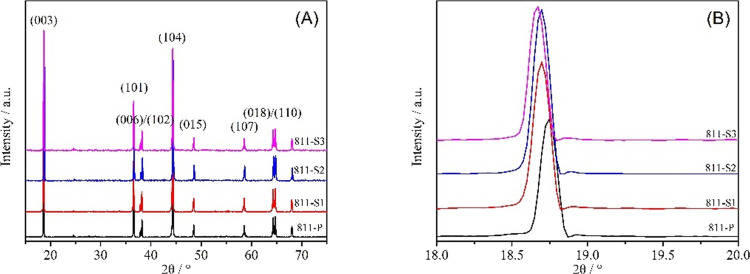
Figure 1 shows the XRD patterns of La3+–Al3+ co-doped NCM811. It can be observed that the positions and intensities of all the diffraction peaks for various samples are following the standard pattern (PDF: 74-0919) with a typical α-NaFeO2 hexagonal layered structure and R3m space group. Furthermore, no detectable impurities can be observed, indicating that La3+ and Al3+ were successfully embedded and introduced as dopants into the NCM811 lattice. Both (006)/(102) and (018)/(110) peaks of pure and doped samples showed significant cleavage, indicating that La3+–Al3+ co-doping did not influence the layered structure.
Figure 1.
(A) XRD patterns and (B) zoomed-in XRD patterns of pure and La3+–Al3+ co-doped NCM811 cathode materials.
The lattice parameters of pure and co-doped samples are shown in Table 1. With the increasing La3+ content, the c value gradually increases. This could happen as the ion radius of La3+ (1.03 Å) is much larger than that of Ni2+ (0.69 Å), leading to an expanded interlayer spacing. At the same time, c/a values of both pure and co-doped samples were large (>4.899), indicating a well-arranged layered structure.26 Generally, the R value ((003)/(104)) is an important parameter used to characterize the degree of Li+/Ni2+ intermixing. It can be observed that this value first increased and then decreased as the amount of doping agent increased. Sample 811-S2 showed the highest R value, indicating that an appropriate amount (La = 0.25%, Al = 0.5%) of doping could reduce the cation intermixing.
Table 1. Lattice Parameters of Pure and La3+–Al3+ Co-doped NCM811 Cathode Materials.
| sample | a (Å) | c (Å) | c/a | R = (003)/(104) |
|---|---|---|---|---|
| 811-P | 2.8736 | 14.2072 | 4.9440 | 1.1178 |
| 811-S1 | 2.8787 | 14.2164 | 4.9384 | 1.2104 |
| 811-S2 | 2.8762 | 14.2213 | 4.9444 | 1.2287 |
| 811-S3 | 2.8754 | 14.2242 | 4.9468 | 1.1213 |
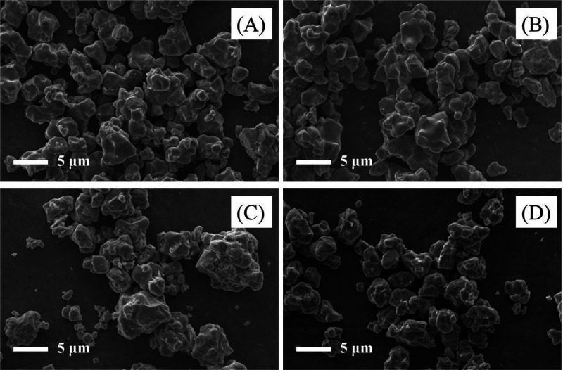
To investigate the influence of La3+–Al3+ co-doping on the morphology of NCM811, SEM micrographs were taken (Figure 2). The particle sizes of all samples were relatively uniform without apparent agglomeration. Furthermore, all the co-doped samples’ morphology remained quasi-unchanged, demonstrating that the introduction of La3+ and Al3+ had little effect on the morphology of the NCM811 cathode material.
Figure 2.
SEM micrographs of La3+–Al3+ co-doped NCM811 samples: (A) 811-P, (B) M811-S1, (C) 811-S2, and (D) 811-S3.
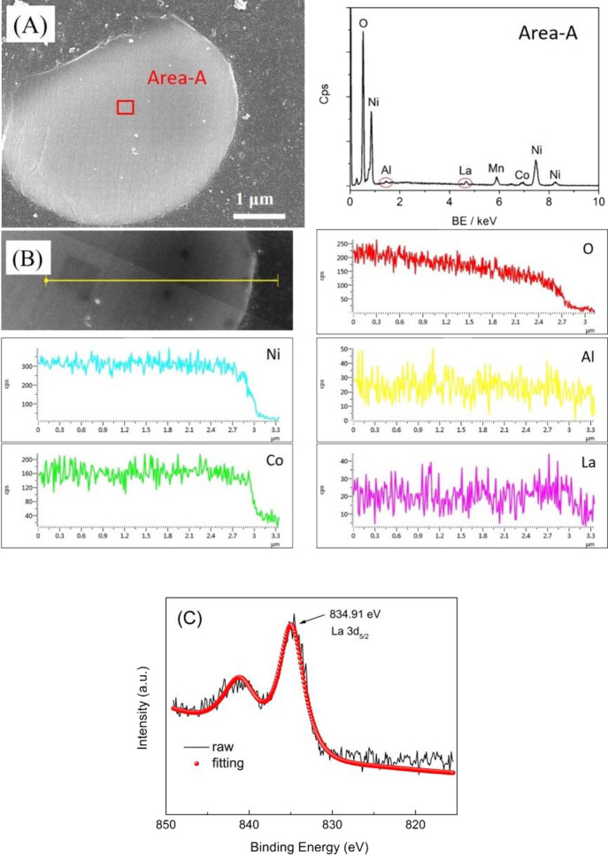
The EDS analysis was performed on the cross section of sample 811-S2 particle to verify that the doping with La3+ and Al3+ was successful (Figure 3), which confirmed that the loading amount of Al3+ and La3+ in this sample was about 0.21 and 0.53%, respectively. According to these results, La and Al elements were uniformly distributed, indicating that La3+ and Al3+ were successfully doped into the NCM811. Moreover, XPS was carried out to explore the valence state of La dopant. The state of La was discussed in Figure 3C, where the peak at 834.91 eV corresponded to 3d5/2 of La3+.
Figure 3.
EDS investigation (A and B) and high-resolution La 3d XPS spectra (C) of sample 811-S2.
3.2. Charge/Discharge Performances
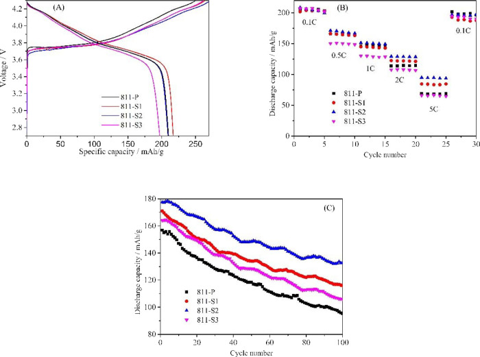
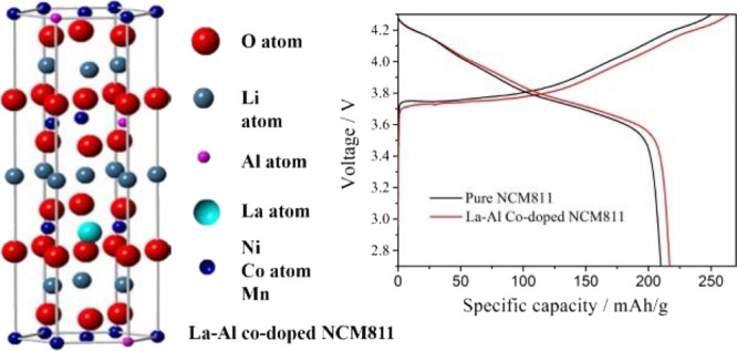
Figure 4 A shows the as-obtained samples’ initial charge/discharge performances at 0.05 C in the range of 2.7–4.3 V (corresponding data are shown in Table 2). The initial specific discharge capacity increased and then decreased as the doping amount increased. Sample 811-S2 displayed the highest initial discharge specific capacity of 216.8 mAh/g, while the initial discharge specific capacity of the undoped sample 811-P was only 196.6 mAh/g. The results indicated that appropriate La3+ and Al3+ co-doping could effectively increase the initial discharge specific capacity. This is because La3+ doping with a large radius can enhance the diffusion of Li+, improving the structural stability of NCM811 and efficiently strengthening the insertion/extraction process of Li+.18 Similarly, it was also reported that Al3+ could replace the Mn4+ site. Thus, it can promote the conversion of Ni2+ to Ni3+, reducing the ratio of Ni2+/(Ni2+ + Ni3+) and decreasing the degree of Li+/Ni2+ intermixing.27
Figure 4.
Initial charge/discharge performances at 0.05 C (A), rate performances (B), and cycling performances at 1 C (C) of pure and co-doped samples.
Table 2. Initial Charge/Discharge Specific Capacities of La3+–Al3+ Co-doped NCM811-Based Samples at 0.05 C.
| sample | 811-P | 811-S1 | 811-S2 | 811-S3 |
|---|---|---|---|---|
| charge capacity (mAh/g) | 252.2 | 263.8 | 273.5 | 260.1 |
| discharge capacity (mAh/g) | 196.6 | 209.8 | 218.6 | 211.5 |
The rate performances of samples are shown in Figure 4B. Although pure and La3+–Al3+ co-doped samples displayed the same performance at a low rate (0.1 C), the discharge specific capacity of co-doped samples was much higher than that of undoped as the discharge current increased (2–5 C). For example, the discharge specific capacity of sample 811-S2 was 98.7 mAh/g, while that of the pure sample was only 48.7 mAh/g at 5 C. This is due to the La3+ and Al3+ co-dopants on the layered structure and crystal development of the NCM811 cathode material.
Figure 4C presents the cycling performances at 1 C in the range of 2.7–4.3 V. The highest initial discharge capacity belongs to sample 811-S2 (178.6 mAh/g at 1 C), while samples 811-P, 811-S1, and 811-S3 showed 148.2, 168.9, and 159.8 mAh/g, respectively. After 100 cycles, the discharge specific capacity of sample 811-S2 was 134.6 mAh/g, with a capacity retention of 75.4%. However, the capacity retention of samples 811-P, 811-S1, and 811-S3 were only 61.8, 68.5, and 67.6%, respectively (values obtained after 100 cycles at 1 C). Consequently, it can be affirmed that the proper amount of La3+ and Al3+ co-dopants can improve the cycle performances of the NCM811 cathode material. This can be attributed mainly to three factors. Firstly, La3+ doping with a large radius enhanced the insertion/extraction of Li+ and decreased the charge/discharge process’ impedance. Secondly, La3+ has a stronger affinity with oxygen, which can inhibit the loss of lattice oxygen and produce fewer oxygen vacancies. Therefore, the doped cathode material’s layered structure became more stable, which is beneficial to the cycle performance.7 Thirdly, Al3+ could act as a positive charge center that can promote the diffusion of Li+. Besides, the intermixing degree of Li+/Ni2+ was reduced due to the substitution of Al3+ for Mn4+, decreasing the proportion of Ni2+/(Ni2+ + Ni3+) and ensuring the order of the NCM811 layered structure.11
3.3. Electrochemical Performances
Figure 5 shows the cyclic voltammetry curves of NCM811-based samples. All samples have two pairs of redox peaks at 3.9 and 4.2 V. The corresponding reduction peaks can be found around 3.6 and 4.1 V. According to previous reports, the largest redox peak observed in the range of 3.6–4.0 V could be attributed to the Ni2+/Ni3+ or Ni4+ transition.28 The other pair of redox peaks could be attributed to Co3+/Co4+.29 As we know, a smaller voltage difference between the oxidation and reduction peaks indicates smaller potential polarization and better electrochemical reversibility of the cathodic material. The voltage difference between the redox peaks of 811-P, 811-S1, 811-S2, and 811-S3 samples was 0.65, 0.54, 0.52, and 0.66 V. The voltage difference between the redox peaks of 811-S2 was the smallest, showing outstanding reversibility.
Figure 5.
Cyclic voltammetry profiles of La3+–Al3+ co-doped NCM811 samples: (A) the first cycle and (B) the second cycle.
The second circle of oxidation peak was observed to shift to a lower potential due to the SEI layer formation. The offset voltage value of 811-P was 0.28 V, while this value of sample 811-S2 was as low as 0.18 V. This indicates that the SEI layer of sample 811-S2 is much thinner than in the case of 811-P during the charge/discharge processes, which could enhance the insertion/extraction of Li+. In summary, the appropriate amount of La3+ and Al3+ can reduce the potential polarization of NCM811, improving the reversibility and the cycle performance. The CV results are in good agreement with the XRD patterns (Figure 1), initial charge/discharge performance, and cycle performance (Figure 4).
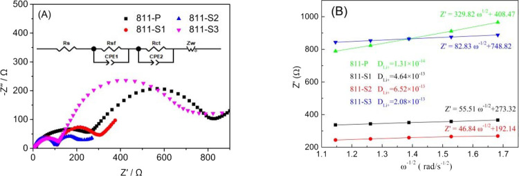
Figure 6 presents the EIS curves of La3+–Al3+ co-doped NCM811, while the inset presents the equivalent circuit. The Z-View software was used to fit the experimental data, and the corresponding impedance values are shown in Table 3. The impedance of the co-doped sample was significantly reduced. The EIS layer’s resistance (Rsf) and the charge transfer resistance (Rct) of sample 811-S2 were only 82.5 and 116.7 Ω, respectively. Simultaneously, the Rsf and Rct values of the undoped sample 811-P were 223.6 and 546.8 Ω, respectively. This shows that the proper amount of La3+ and Al3+ co-doping can reduce the impedance of NCM811, increasing the conductivity. Besides, Al3+ as a positive charge center also promotes the diffusion of Li+. However, as the amount of doping agent increases, the samples’ Rsf and Rct values increase as well. This is also because the radius of La3+ is relatively large: if the doping amount is too large, the lattice distortion increases and the order of the layered structure decreases, increasing the cathode’s impedance. Moreover, the diffusion coefficients of lithium-ion (DLi+) in the cathodes were calculated from the slopes of the fitted lines in Figure 6B; sample 811-S2 showed the highest DLi+ (6.52 × 10⁻¹³). This is because the La3+ doping with a large radius increases the interlayer spacing, which is beneficial to the insertion/extraction of Li+.
Figure 6.
EIS curves of La3+–Al3+ co-doped NCM811 samples (A) and the Z′−ω–1/2 relationship (B).
Table 3. Equivalent Resistance Values of La3+–Al3+ Co-doped NCM811.
| sample | Rs (Ω) | Rsf (Ω) | Rct (Ω) |
|---|---|---|---|
| 811-P | 4.2 | 223.6 | 546.8 |
| 811-S1 | 4.1 | 99.8 | 145.3 |
| 811-S2 | 4.8 | 82.5 | 116.7 |
| 811-S3 | 3.6 | 136.8 | 635.5 |
4. Conclusions
La3+ and Al3+ co-doped NCM811 materials were successfully synthesized via a solid-state reaction. The effects of doping concentrations on the phase structure, micromorphology, and electrochemical performance of NCM811 were discussed in depth. The results showed that when La and Al doping concentrations were 0.25 and 0.5%, the sample showed the best performance in terms of capacity and retention. The initial discharge specific capacity was 218.6 mAh/g (0.05 C) and 178.6 mAh/g (1 C). After 100 cycles at 1 C, the discharge specific capacity was 134.6 mAh/g with 75.4% capacity retention. These excellent performances were assigned to the low cation intermixing, stable structure, and low potential polarization and impedance during the charge/discharge process after co-doping with La and Al.
Acknowledgments
This work was supported by the National Natural Science Foundation of China (11904128 and 32060308) and Doctoral Initiated Research Foundation Project under Grant BSKJ201822.
The authors declare no competing financial interest.
References
- Jiang J.; Du K.; Cao Y.; Peng Z.; Hu G.; Duan J. Syntheses of spherical LiMn2O4 with Mn3O4 and its electrochemistry performance. J. Alloys Compd. 2013, 577, 138–142. 10.1016/j.jallcom.2013.04.144. [DOI] [Google Scholar]
- Wu F.; Tian J.; Su Y.; Wang J.; Zhang C.; Bao L.; He T.; Li J.; Chen S. Effect of Ni2+ content on lithium/nickel disorder for Ni-rich cathode materials. ACS Appl. Mater. Interfaces 2015, 7, 7702–7708. 10.1021/acsami.5b00645. [DOI] [PubMed] [Google Scholar]
- Tan X.; Zhang M.; Li J.; Zhang D.; Yan Y.; Li Z. Recent progress in coatings and methods of Ni-rich LiNi0.8 Co0.1Mn0.1O2 cathode materials: A short review. Ceram. Int. 2020, 46, 21888–21901. 10.1016/j.ceramint.2020.06.091. [DOI] [Google Scholar]
- Myung S.-T.; Maglia F.; Park K.-J.; Yoon C. S.; Lamp P.; Kim S.-J.; Sun Y.-K. Nickel-Rich layered cathode materials for automotive lithium-ion batteries: achievements and perspectives. ACS Energy Lett. 2017, 2, 196–223. 10.1021/acsenergylett.6b00594. [DOI] [Google Scholar]
- Kondrakov A. O.; Geßwein H.; Galdina K.; de Biasi L.; Meded V.; Filatova E. O.; Schumacher G.; Wenzel W.; Hartmann P.; Brezesinski T.; Janek J. Charge transfer-induced lattice collapse in Ni-rich NCM cathode materials during delithiation. J. Phys. Chem. C 2017, 121, 24381–24388. 10.1021/acs.jpcc.7b06598. [DOI] [Google Scholar]
- Li J.; Zhang M.; Zhang D.; Yan Y.; Li Z. An effective doping strategy to improve the cyclic stability and rate capability of Ni-rich LiNi0.8Co0.1Mn0.1O2 cathode. Chem. Eng. J. 2020, 402, 126195. 10.1016/j.cej.2020.126195. [DOI] [Google Scholar]
- Dong M.-x.; Li X.-q.; Wang Z.-x.; Li X.-h.; Guo H.-j.; Huang Z. J. Enhanced cycling stability of La modified LiNi0.8-xCo0.1Mn0.1LaxO2 for Li-ion battery. Trans. Nonferrous Met. Soc. China 2017, 27, 1134–1142. 10.1016/S1003-6326(17)60132-8. [DOI] [Google Scholar]
- Yue P.; Wang Z.; Wang J.; Guo H.; Xiong X.; Li X. Effect of fluorine on the electrochemical performance of spherical LiNi0.8Co0.1Mn0.1O2 cathode materials via a low temperature method. Powder Technol. 2013, 237, 623–626. 10.1016/j.powtec.2012.12.061. [DOI] [Google Scholar]
- Du R.; Bi Y.; Yang W. C.; Peng Z.; Liu M.; Liu Y.; Wu B.; Yang B.; Ding F.; Wang D. Improved cyclic stability of LiNi0.8Co0.1Mn0.1O2 via Ti substitution with a cut-off potential of 4.5V. Ceram. Int. 2015, 41, 7133–7139. 10.1016/j.ceramint.2015.02.026. [DOI] [Google Scholar]
- Li L. J.; Wang Z. X.; Liu Q. C.; Ye C.; Chen Z. Y.; Gong L. Effects of chromium on the structural, surface chemistry and electrochemical of layered LiNi0.8-xCo0.1Mn0.1CrxO2. Electrochim. Acta 2012, 77, 89–96. 10.1016/j.electacta.2012.05.076. [DOI] [Google Scholar]
- Chen M.; Zhao E.; Chen D.; Wu M.; Han S.; Huang Q.; Yang L.; Xiao X.; Hu Z. Decreasing Li/Ni disorder and improving the electrochemical performances of Ni-rich LiNi0.8Co0.1Mn0.1O2 by Cadoping. Inorg. Chem. 2017, 56, 8355–8362. 10.1021/acs.inorgchem.7b01035. [DOI] [PubMed] [Google Scholar]
- GAO S.; ZHAN X.; CHENG Y. T. Structural, electrochemical and Li-ion transport properties of Zr-modified LiNi0.8Co0.1Mn0.1O2 positive electrode materials for Li-ion batteries. J. Power Sources 2019, 410-411, 45–52. 10.1016/j.jpowsour.2018.10.094. [DOI] [Google Scholar]
- Xiao Z.; Zhou C.; Song L.; Cao Z.; Jiang P. Dual-modification of WO3-coating and Mg-doping on LiNi0.8Co0.1Mn0.1O2 cathodes for enhanced electrochemical performance at high voltage. Ionics 2021, 27, 1909–1917. 10.1007/s11581-021-03997-z. [DOI] [Google Scholar]
- Liu J.; Zou Z.; Zhong S.; Zhang S.; Zhang H. Improved electrochemical performance of magnesium-doped LiNi0.8-xMgxCo0.1Mn0.1O2 by CTAB-assisted solvothermal and calcining method. Ionics 2021, 27, 1501–1509. 10.1007/s11581-021-03925-1. [DOI] [Google Scholar]
- Xu T.; Liu C.; Guo Z.; Li W.; Li Y.; Yang G. Improved rate and cyclic performance of potassium-doped nickel-rich ternary cathode material for lithium-ion batteries. J. Mater. Sci. 2021, 56, 2399–2411. 10.1007/s10853-020-05306-x. [DOI] [Google Scholar]
- Yuan A.; Tang H.; Liu L.; Ying J.; Tan L.; Tan L.; Sun R. G. High performance of phosphorus and fluorine co-doped LiNi0.8Co0.1Mn0.1O2 as a cathode material for lithium ion batteries. J. Alloys Compd. 2020, 84, 156210. 10.1016/j.jallcom.2020.156210. [DOI] [Google Scholar]
- Nanthagopal M.; Santhoshkumar P.; Shaji N.; Sim G. S.; Park J. W.; Senthil C.; Lee C. W. An encapsulation of nitrogen and sulphur dual-doped carbon over Li [Ni0.8Co0.1Mn0.1]O2 for lithium-ion battery applications. Appl. Surf. Sci. 2020, 145580. 10.1016/j.apsusc.2020.145580. [DOI] [Google Scholar]
- Min K.; Seo S. W.; Song Y. Y.; Lee H. S.; Cho E. A first-principles study of the preventive effects of Al and Mg doping on the degradation in LiNi0.8Co0.1Mn0.1O2 cathode materials. Phys. Chem. Chem. Phys. 2017, 19, 1762–1769. 10.1039/c6cp06270a. [DOI] [PubMed] [Google Scholar]
- Liang C.; Kong F.; Longo R. C.; Zhang C.; Nie Y.; Zheng Y.; Cho K. Site-dependent multi component doping strategy for Ni-rich LiNi1-2yCoyMnyO2(y=1/12) cathode materials for Li-ion batteries. J. Mater. Chem. A 2017, 5, 25303–25313. 10.1039/c7ta08618k. [DOI] [Google Scholar]
- Naghash A. R.; Lee J. Y. Lithium nickel oxy fluoride (Li1-zNi1+ zFyO2-y) and lithium magnesium nickel oxide (Li1-z(MgxNi1-x)1+ zO2) cathodes for lithium rechargeable batteries: Part I. Synthesis and characterization of bulk phases. Electrochim. Acta 2001, 46, 2293–2304. 10.1016/S0013-4686(01)00452-2. [DOI] [Google Scholar]
- Liang Y.; Li S.; Xie J.; Yang L.; Li W.; Li C.; Ai L.; Fu X.; Cui X.; Shangguan X. Synthesis and electrochemical characterization of Mg–Al co-doped Li-rich Mn-based cathode materials. New J. Chem. 2019, 43, 12004–12012. 10.1039/C9NJ01539F. [DOI] [Google Scholar]
- Liu Q.; Su X.; Lei D.; Qin Y.; Wen J.; Guo F.; Wu Y.; Rong Y.; Kou R.; Xiao X.; Aguesse F.; Bareño J.; Ren Y.; Lu W.; Li Y. Approaching the capacity limit of lithium cobalt oxide in lithium ion batteries via lanthanum and aluminium doping. Nat. Energy 2018, 3, 936–943. 10.1038/s41560-018-0180-6. [DOI] [Google Scholar]
- Xiao Z. W.; Zhang Y. J.; Wang Y. F. Synthesis of high-capacity LiNi0.8Co0.1Mn0.1O2 cathode by transition metal acetates. Trans. Nonferrous Met. Soc. China 2015, 25, 1568–1574. 10.1016/S1003-6326(15)63759-1. [DOI] [Google Scholar]
- Trevisanello E.; Ruess R.; Conforto G.; Richter F. H.; Janek J. Polycrystalline and Single Crystalline NCM Cathode Materials—Quantifying Particle Cracking, Active Surface Area, and Lithium Diffusion. Adv. Energy Mater. 2021, 11, 2003400. 10.1002/aenm.202003400. [DOI] [Google Scholar]
- Zhang M.; Shen J.; Li J.; Zhang D.; Yan Y.; Huang Y.; Li Z. Effect of micron sized particle on the electrochemical properties of nickel-rich LiNi0.8Co0.1Mn0.1O2 cathode materials. Ceram. Int. 2020, 46, 4643–4651. 10.1016/j.ceramint.2019.10.195. [DOI] [Google Scholar]
- Lin S. P.; Fung K. Z.; Hon Y. M.; Hon M. H. Effect of Al addition on formation of layer-structured LiNiO2. J. Solid State Chem. 2002, 167, 97–106. 10.1006/jssc.2002.9624. [DOI] [Google Scholar]
- Lei T.; Li Y.; Su Q.; Cao G.; Li W.; Chen Y.; Xue L.; Deng S. High-voltage electrochemical performance of LiNi0.5Co0.2Mn0.3O2 cathode materials via Al concentration gradient modification. Ceram. Int. 2018, 44, 8809–8817. 10.1016/j.ceramint.2018.02.053. [DOI] [Google Scholar]
- Zhang S. S.; Xu K.; Jow T. R. Electrochemical impedance study on the low temperature of Li-ion batteries. Electrochim. Acta 2004, 49, 1057–1061. 10.1016/j.electacta.2003.10.016. [DOI] [Google Scholar]
- Li Y. C.; Zhao W. M.; Xiang W.; Wu Z. G.; Yang Z. G.; Xu C. L.; Xu Y. D.; Wang E. H.; Wu C. J.; Guo X. D. Promoting the electrochemical performance of LiNi0.8Co0.1Mn0.1O2 cathode via LaAlO3 coating. J. Alloys Compd. 2018, 766, 546–555. 10.1016/j.jallcom.2018.06.364. [DOI] [Google Scholar]


