Abstract
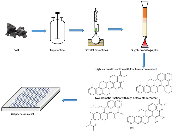
Despite its complex structure, coal has shown to be a promising precursor for graphene synthesis by chemical vapor deposition (CVD). However, the presence of heteroatoms and aliphatic chains in coal can lead to defects in the graphene lattice, preventing the formation of pristine graphene layers. Therefore, the goal of this study was to formulate a multistep coal fractionation scheme to extract and characterize the most aromatic fractions and explore their potential as graphene precursors. The scheme consisted of direct coal liquefaction under different conditions, Soxhlet extraction with heptane then toluene, and preparative liquid chromatography on silica gel using heptol solutions with different heptane/toluene ratios. The fractions obtained by this process were analyzed by proton nuclear magnetic resonance, thermogravimetric and elemental analyses, and automated SAR-AD (saturates, aromatics, resins-asphaltene determinator) separations. This characterization allowed the identification of two aromatic fractions with and without heteroatoms, which were subsequently used for graphene synthesis by CVD on nickel and copper foils. Raman spectrometry revealed that both fractions primarily formed defect-free multilayered graphene with approximately 11 layers on nickel due to the high solubility of carbon and the defect-healing effect of nickel. On the other hand, these fractions generated amorphous carbon on copper due to the high solubility of hydrogen in copper, which competed with carbon. Molecules in the more aromatic heteroatom-free fraction still contained alkyl pendant substituents and did not share the same planarity and symmetry to form defect-free graphene on copper. Thus, the quality of graphene was governed by the substrate on nickel and by the precursor quality on copper. When deposited directly on lacey carbon-coated copper grids of a transmission electron microscope, the heteroatom-free fraction gave rise to much larger graphene domains. The presence of heteroatoms promoted the formation of small self-assembled agglomerates of amorphous carbon.
1. Introduction
Graphene is a two-dimensional monolayer of sp2 hybridized carbon atoms.1 Since its discovery in 2007, graphene has been in demand among researchers for its exceptional chemical and physical properties.1−5 Graphene synthesis methods can be broadly divided into two categories, viz, the top-down approach, and bottom-up approach. Top-down methods such as mechanical exfoliation,6 arc discharge,7 and chemical reduction involve breaking down or isolating large polycyclic aromatic hydrocarbon (PAH) molecules into graphene.6−8 These methods provide high yields but many structural defects. On the other hand, bottom-up methods such as chemical vapor deposition (CVD) work by stitching individual carbon atoms/molecules to form graphene.9,10 The graphene formed by these methods is highly pristine but has low yields.
CVD is a promising and facile method for synthesis of large and pristine graphene sheets for use in electronics.10−14 Yet, it requires expensive carbon precursors such as acetylene, ethylene, methane, and so forth.14−17 Recent studies have shown that abundant and inexpensive precursors such as coal could be used instead.10,18,19 Coal is a complex mixture of hydrocarbons, in which individual molecules are arranged in archipelago patterns with islands of PAHs connected by aliphatic chains. The latter form three-dimensional networks due to aromatic stacking, hydrogen bonding, and acid–base interactions.20 The PAHs are essential components and building blocks of graphene-based nanomaterials; however, they are difficult to extract from coal. As a result, graphene synthesized directly from coal contains high amounts of defects due to the alkyl chains and heteroatoms present in the molecules.19,21 Research has shown that symmetry and planarity of PAHs can affect the quality of graphene in CVD.22 Precursor molecules that are highly symmetric and planar can form more pristine graphene as compared to asymmetric and nonpolar molecules. In addition, the presence of heteroatoms contributes to defects in the graphene lattice structure.23 Thus, in theory, if we can fractionate coal into highly aromatic and heteroatom-free fractions, we can synthesize pristine graphene from it.
The fractionation of coal can be achieved by different techniques such as direct liquefaction, solvent solubility,24−26 silica-gel chromatography,27 size exclusion chromatography,28 and thin-layer chromatography.29 Each of these processes can separate fractions based on different characteristics such as solubility, polarity, and so forth. Hence, these techniques can be combined to formulate a fractionation scheme to isolate a particular type of molecules.
In this work, we have formulated a multistep fractionation process to isolate highly aromatic fractions from coal. The process consisted of direct coal liquefaction (DCL) at different temperatures, solvent extraction, and silica-gel liquid chromatography. The fractions obtained in each step were characterized by thermogravimetric, spectroscopic, and chromatographic techniques. Among the fractions separated, a highly aromatic fraction without heteroatoms and another less aromatic fraction with heteroatoms were used to synthesize graphene by CVD on nickel (Ni) and copper (Cu). The synthesized graphene was analyzed by Raman spectrometry to assess its quality on both substrates. CVD was also performed directly on transmission electron microscopy (TEM) grids to examine structural differences between the two graphene materials and highlight the role of heteroatoms.
2. Experimental Section
2.1. Materials
Sub-bituminous powder river basin (PRB) coal from Wyoming was used as a precursor. The coal was sieved to 300 mesh size and then dried under a nitrogen atmosphere at 110 °C for 24 h. The properties of PRB coal are shown in Table 1. For liquefaction and fractionation, silica gel and HPLC-grade solvents (tetralin, heptane, and toluene) were procured from Sigma-Aldrich. Annealed copper (99.8% metal basis) and nickel foils (99.5% metal basis) were purchased from Alfa Aesar. The certified standard 10% hydrogen in argon was obtained from Rocky Mountain Air. The HPLC-grade solvents (cyclohexane, toluene, dichloromethane, and methanol) for SAR-AD analysis were obtained from Fisher Scientific. Deuterated chloroform was purchased from Cambridge Isotope laboratories.
Table 1. Properties of PRB Coal.
| analysis | value | ASTM method |
|---|---|---|
| moisture (wt %) | 1.36 | D7582 |
| ash (wt %) | 7.05 | D7582 |
| volatile Matter (wt %) | 41.06 | D7582 |
| heating value (BTU/Lb) | 9654 | D5865 |
| carbon (wt %) | 64.88 | D5373 |
| hydrogen (wt %) | 4.54 | D5373 |
| nitrogen (wt %) | 1.96 | D5373 |
| sulfur (wt %) | 0.61 | D4239 |
| oxygen (wt %) | 19.60 | calculated |
2.2. Coal Liquefaction and Fractionation
DCL is a reductive pyrolysis process of breaking down large coal molecules into smaller ones by using a hydrogen-donating solvent.30 Here, DCL was performed with tetralin under 1000 psi nitrogen atmosphere. In all the experiments, 60 g of coal was dried for 24 h under a nitrogen atmosphere and added to 240 mL of tetralin. The reaction was continued for 3 h at different temperature conditions: 350, 400, and 450 °C. The fraction of coal tar that dissolved in tetralin was termed as tetralin solubles (TTS), and the remaining was the tetralin insoluble fraction (TTIS). TTS was subjected to vacuum distillation on a high vacuum line and an oil bath set to 300 °C to remove the tetralin and then subjected to Soxhlet extraction with heptane as a solvent. The extraction worked by slow diffusion of analytes from the sample matrix to the extraction solvent31 and yielded a heptane soluble (HS) and a heptane insoluble (HIS) fraction. A toluene Soxhlet extraction was performed on the HIS, which further gave a toluene soluble (TS) and toluene insoluble fraction (TIS). The solvents were removed from HS and TS by a rotavapor, and the samples were dried in a vacuum oven. Next, 350 mg of the sample was dissolved in dichloromethane and added to the silica gel, and the solvent was removed by rotary evaporation. The packed activated silica column was loaded with heptane, and the top of the column was layered with sand and then the preadsorbed silica sample. The heptane–toluene mixtures (heptol) were introduced in the column by increasing polarity, starting from 100% heptane. This was followed by heptol (80:20), heptol (50:50), and 100% toluene. The fractions eluted from each solvent step were collected, dried using a rotavapor, and dried in a vacuum oven. The conversion from coal to the subfractions are shown in Figure S1.
2.3. Graphene Synthesis
The graphene synthesis setup is shown in Figure 1. The carbon source (20 mg) was placed in a boat in furnace 1, and the substrates (nickel and copper foils and TEM copper grid) were placed in furnace 2. The substrates contributed to the decomposition of carbon species (as catalysts) and the nucleation of carbon atoms. The carrier gas consisted of 10% hydrogen in argon. Furnace 2 was first heated to 1000 °C under ultrahigh vacuum (10–6 hPa). Furnace 1 was then heated to 400 °C, and the flow of carrier gas was started. The vacuum decreased to about 10–3 hPa during gas flow. The gas was stopped after 30 min of flow, and the vacuum was again increased to 10–6 hPa for 30 min. The furnaces were then cooled quickly (within 30–40 min), and the substrates were collected and analyzed by Raman spectrometry and TEM.
Figure 1.
Graphene synthesis setup by CVD.
2.4. Characterization of Coal Fractions and Graphene
A Bruker AVANCE III 400 MHz nuclear magnetic resonance (NMR) spectrometer was used to obtain the aromatic and aliphatic content of the fractions. The samples were prepared by dissolving 20 mg of the sample in 0.5 cm3 deuterated chloroform. A coupled proton pulse program was used, and topspin 3.0 software was used to analyze the data. The spectra were then divided into different fractions by integrating sections of the spectra.32 The Saturates, Aromatics, Resins-Asphaltene Determinator (SAR-AD) developed by the Western Research Institute (WRI) was used to quantify the relative contents of these fractions.33 The SAR-AD method is an automated HPLC separation which couples chromatography and solubility separations in series. The hydrocarbon material is initially separated into maltenes (heptane-soluble) and asphaltenes (heptane-insoluble). The maltene part is further separated by chromatography on three different sorbents with different solvents, while the asphaltenes are separated using solubility with three different solvents of increasing solvent strength: cyclohexane, toluene, and dichloromethane/methanol. The different fractions produced by the separation are saturates (Sat), 1-ring aromatics (Aro 1), 2–3-ring aromatics, and pericondensed pyrene (Aro 2), 4+-ring aromatics (Aro 3), aromatics containing more polar heteroatom functional groups such as ketones, esters, and phenolics (resins) and three fractions of asphaltenes with increasing polarity and aromaticity: CyC6, toluene, and CH2Cl2:MeOH. The different fractions are quantified by an evaporative light scattering detector, which gives values which are very close to gravimetric values. Carbon, hydrogen, nitrogen, oxygen, and sulfur elemental analysis was performed by ALS Global. The elements C, H, and N were quantified by D 5373. Oxygen and sulfur were quantified by D 5373 mod and D 4239, respectively. Thermogravimetric analysis (TGA) was performed by a TA Instruments Q5000 TGA using nitrogen and a heating rate of 20 °C/min to evaluate the boiling point of each fraction. Raman spectra of the synthesized graphene were obtained by using a Raman spectrometer developed at the Rice research group with a 532 nm laser. Raman maps were collected on a DXR2 Raman microscope from ThermoFisher Scientific with a 532 nm laser. The Raman spectra were collected over an area of 600 × 400 μm with 50 μm distance between the points. The excitation power of the laser was 10 mW with a spot size of 3.6 ± 0.3 μm with an exposure time of 5 s. The spectra were resolved on a 750 nm blazed, 1200 grooves/mm grating using a 320 mm isoplane spectrometer and a LN2-cooled Si CCD. An FEI Tecnai transmission electron microscope was used to measure the size and structure of the graphene film. All images were taken under a high tension of 200 kV. Mh mode was utilized in the imaging process. Lacey carbon grids from Ted Pella were used to support the graphene film and provide better contrast during the imaging procedure.
3. Results and Discussion
3.1. Coal Liquefaction and Characterization
Table 2 presents the yields of tetralin-soluble fractions (L1, L2, L3) after coal liquefaction at three different temperatures. As expected, DCL was highly dependent on the temperature of the process.31 The increase in temperature from 350–400 °C led to an increase in the conversion of the tetralin-soluble fraction. The decomposition of molecules is enhanced by performing DCL at a temperature above pyrolysis (360 °C). However, when going significantly above pyrolysis (>400 °C), coke formation competes with the extraction and degradation of the coal molecules.
Table 2. Coal Liquefaction Yields.
| liquefaction fraction | temperature (°C) | maximum pressure (psi) | starting dried coal (g) | tetralin soluble (g) | conversion (%) |
|---|---|---|---|---|---|
| L1 | 350 | 2347 | 60 | 8.54 | 14.23 |
| L2 | 400 | 3070 | 60 | 18.76 | 31.26 |
| L3 | 450 | 4011 | 60 | 16.75 | 27.91 |
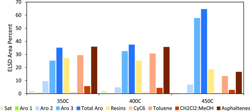
Figure 2 shows the SAR-AD content of the distilled residues (TTS) from the liquefactions. It is evident that liquefaction at 450 °C generated the highest content of total aromatics among the three liquefactions. This is expected because the experiment was conducted above pyrolysis temperatures, leading to cleavage of some functional groups, aliphatic side chains (paraffinic, branched, or naphthenic) while increasing aromaticity. The aromatic fractions contained high amounts of small aromatic molecules with low heteroatoms (primarily ethers, if present). This TTS also contains the least amount of resins and asphaltenes, which is also consistent with pyrolysis as these molecules are either fragmented into smaller aromatics and/or converted to coke. In general, as the temperature increases, the aromatics increase, and the saturates, resins, and asphaltenes decrease. From the standpoint of producing PAHs for graphene synthesis, distilled residues from 450 °C liquefaction (i.e., TTS L3) would be the best sample for further fractionation due to relatively high aromatic and low resin and asphaltene contents.
Figure 2.
SAR-AD analysis of the tetralin-soluble distilled residues after coal liquefaction at 350, 400, and 450 °C.
The elemental composition of the distilled residues from the three liquefactions is provided in Table 3. The amount of carbon increased, while the amount of hydrogen decreased with an increase in temperature. This implied that the higher liquefaction temperature led to a higher aromatic tetralin soluble fraction. Also, the amount of total heteroatom content decreased with an increase in the liquefaction temperature. This is consistent with expectations for pyrolysis and further confirms the SAR-AD data.
Table 3. Elemental Composition for the Liquefaction-Distilled Residues.
| temperature (°C) | carbon (%) | hydrogen (%) | nitrogen (%) | oxygen (%) | sulfur (%) |
|---|---|---|---|---|---|
| 350 | 82.49 | 7.84 | 0.51 | 7.59 | <0.3 |
| 400 | 84.70 | 7.03 | 0.93 | 6.63 | <0.3 |
| 450 | 87.57 | 6.15 | 0.99 | 4.29 | <0.3 |
Sequential Soxhlet extractions were then performed on the distilled liquefaction residues to reduce the heteroatom content and increase aromaticity. Heptane was used to isolate mostly nonpolar aromatic compounds since small PAH molecules are highly soluble in hot heptane, while toluene was used to isolate larger PAH molecules and polar aromatics containing more heteroatoms. It should be noted that Soxhlet extractions of DCL products leads to some overlap in the molecules between different solvents. This is due to cosolubility effects that occur when the coal fractions become dissolved in the extracting solvent, which changes the solubility parameter of the extraction solvent. The heat increases the kinetic energy of the solute molecules, making them easier to be dissolved. Thus, heptane dissolved some slightly polar compounds as well. Nonetheless, most of the aromatic components were still left behind in the HIS fraction. This fraction was further subjected to Soxhlet extraction with toluene to obtain the most aromatic compounds. Toluene dissolved almost all of the HIS fraction at high temperatures, leaving a minute fraction being toluene-insoluble.
The peak integration results for 1H NMR of HS and TS fractions from all three distilled residues are displayed in Table 4. As expected by the SAR-AD and elemental data, as the DCL temperature increases, there is a significant increase in the aromatic content in the TTS. The HS fraction from 350 and 400 °C distilled residues contained mostly aliphatic protons. This is because saturates are also included in this fraction, as well as aromatics, which contain a high degree of aliphatic substitutions. In contrast, the aromaticity is much higher in the TS fractions because many of the aromatics containing aliphatic side groups, and low amounts of heteroatoms, were extracted in heptane. The aromaticity of the HS and TS fractions from the 450 °C distilled residue is mostly due to the aromatic and not olefinic protons as compared to the 350 and 400 °C HS and TS fractions. This is also another evidence for pyrolysis enhancing the aromaticity of the TTS.
Table 4. 1H NMR for Soxhlet Extractions of the Liquefaction Distilled Residues.
| functional group | 350C HS | 350C TS | 400C HS | 400C TS | 450C HS | 450C TS |
|---|---|---|---|---|---|---|
| aromatic H | 14.73 | 23.56 | 16.11 | 27.27 | 41.12 | 46.08 |
| olefinic CH | 1.18 | 8.23 | 2.79 | 3.49 | 1.25 | 2.86 |
| aliphatic H | 84.10 | 68.21 | 81.09 | 69.25 | 57.63 | 51.07 |
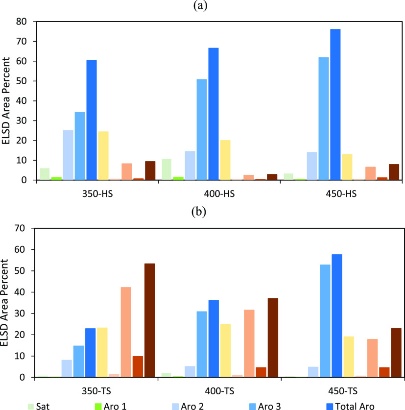
Figure 3 shows the SAR-AD data for HS and TS fractions from all the liquefactions. The established trends showing an increase in aromatics and decrease in resins and asphaltenes with an increase in temperature are consistent with the Soxhlet extractions. The HS fractions from all the liquefactions had higher aromatic fractions as compared to the TS fractions. As compared to the liquefaction TTS, the HSs are most concentrated in aromatics, while the TSs had comparatively slightly lower aromatics and more resins and asphaltenes. Thus, the HS fractions were mostly composed of aromatics, as expected.
Figure 3.
SAR-AD analysis of the HS (a) and TS (b) fractions of the distilled residues after coal liquefaction at 350, 400, and 450 °C.
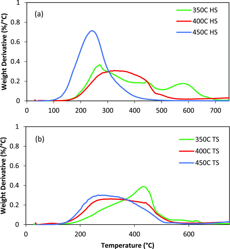
The differential TGA plots for HS and TS fractions from the three liquefactions are shown in Figure 4. The proportion of components at each stage of the analysis is also provided in Table S1. All the TS fractions showed a wide range of boiling point distribution from around 100–700 °C. It should be noted that the material which is volatilized below 400 °C under these conditions consists of free molecules, while the material which volatilizes above 400 °C is a combination of free molecules and molecule fragments generated by pyrolysis. This can be clearly seen in the difference between the 350 °C fraction and the 400 °C fraction and especially, the 450 °C fractions. As pyrolysis increases from 350 < 400 < 450 °C, there is a shift in the volatile material to lower temperatures. This is because pyrolysis has broken larger molecules into smaller fragments. The more Gaussian distribution of the 400 and 450 °C fractions also indicates that many of these the >400 °C volatiles are free molecules and not generated by pyrolysis. In addition, the HS fractions consist of mainly volatiles (up to 430 °C) and pyrolysis (430–800 °C) components. In particular, the 450 HS is mainly composed of lighter volatile molecules. In comparison, the TS fractions have lot more of the combustibles (combusted in air at 800 °C).
Figure 4.
TGA analysis of the HS (a) and TS (b) fractions obtained from the Soxhlet extractions.
Since the HS and TS fractions from the liquefaction at 450 °C clearly had higher aromatic content, a lower-boiling point distribution with little pyrolysis carbon, and less heteroatoms, they were further characterized. The elemental composition of these fractions is shown in Table 5. Both fractions had very high C/H ratios. The HS had a slightly lower aromaticity, as seen by 1H NMR and hence higher hydrogen content. The heteroatom content was reduced substantially as compared to the liquefaction distilled residue. It is likely that most heteroatoms were left behind with the heavier molecules in the TIS.
Table 5. Elemental Composition of the HS and TS Fractions from the Liquefaction at 450 °C.
| fraction | carbon (%) | hydrogen (%) | nitrogen (%) | oxygen (%) | sulfur (%) |
|---|---|---|---|---|---|
| HS | 88.83 | 7.24 | 0.61 | 0.86 | <0.15 |
| TS | 88.37 | 5.99 | 1.45 | 4.50 | <0.17 |
The HS and TS fractions from the liquefaction at 450 °C had the highest aromatic content. However, they still contained some heteroatoms in polar compounds such as resins and asphaltenes. The HS fraction contains 1.47 wt % of N and O, while the HIS fraction contains 5.95 wt % of N and O. For this reason, these fractions were subsequently purified by silica gel chromatography to further isolate the highly aromatic fractions without any heteroatoms. The HS and TS samples were loaded onto preparative columns and eluted with heptol solutions with different heptane/toluene ratios to separate the compounds based on their aromaticity and polarity. The separated fractions were analyzed using the previous characterization techniques. Table 6 shows the 1H NMR data of the Si-gel chromatographic fractions. The heptane-eluted fractions were mostly aliphatic with around 10% aromatic hydrogen. This fraction is mainly composed of saturated hydrocarbons. The heptol (80:20) fraction has the highest aromatic hydrogens at around 50%. The aromaticity decreases with a further increase in toluene concentration. This is assumed to be due to an increase in heteroatoms which is evident from the increasing intensity of yellow to orange color with increasing amounts of toluene. It is important to note that 1H NMR does not account for quaternary aromatic carbons. Thus, real aromaticity must be much higher.
Table 6. 1H NMR Data of the Chromatographic Subfractions of HS and TS Fractions from the Liquefaction at 450 °C Eluted by Heptol Solutions with Different Heptane/Toluene Ratios.
| HS |
TS |
|||||||
|---|---|---|---|---|---|---|---|---|
| functional group | heptane | heptol (80:20) | heptol (50:50) | toluene | heptane | heptol (80:20) | heptol (50:50) | toluene |
| aromatic H | 9.99 | 49.30 | 33.64 | 30.89 | 6.89 | 46.13 | 42.80 | 34.43 |
| olefinic CH | 0.00 | 0.00 | 1.47 | 4.42 | 3.36 | 0.00 | 1.15 | 3.58 |
| aliphatic H | 90.01 | 50.70 | 64.89 | 64.68 | 89.76 | 53.87 | 56.05 | 62.00 |
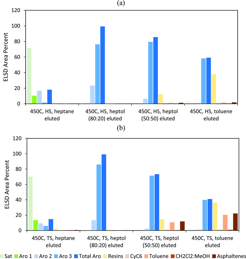
The SAR-AD analysis of these eluents is shown in Figure 5. The heptane-eluted fraction contained mostly saturates due to low polarity of heptane. As the polarity, solubility parameter, and chromatographic strength increased with increasing toluene, more heteroatom-containing molecules are eluted. This is shown by the increase in the resins and asphaltenes with increasing toluene. The fraction eluted by heptol (80:20) consisted of around 99% of nonpolar aromatics. Increasing the toluene concentration further led to the elution of more polar aromatics such as resins and asphaltenes.
Figure 5.
SAR-AD analysis of the chromatographic subfractions of HS (a) and TS (b) fractions from the liquefaction at 450 °C, eluted by heptol solutions with different heptane/toluene ratios.
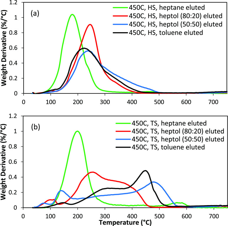
Figure 6 illustrates the differential TGA thermograms of the subfractions extracted by Si-gel chromatography using the HS and TS fractions from the liquefaction at 450 °C. The proportion of components at each stage of the analysis is also given in Table S2. The subfractions eluted from the HS fraction had a very low boiling point (<400 °C), which is consistent with the original 450 °C HS. In particular, the heptane-eluted subfraction had the lowest boiling point with a narrow distribution. The other fractions had a similar boiling point distribution with the 50:50 and toluene fractions containing heavier materials tailing out to beyond 400 °C. On the other hand, the fractions eluted from the TS fraction had larger boiling points and significantly more material which decomposes due to pyrolysis above 400 °C. The heptane-eluted fraction had the lowest boiling point with a narrow distribution. As the polarity of the solvent increased, the boiling point and pyrolysis carbon increased as well. This is because, as the polarity of the solvent increases, it elutes molecules with higher molecular weight, more heteroatoms, and likely a more complex structure with linked aromatics. The heptane and heptol (80:20) eluted fractions are mainly composed of the lighter volatile molecules with negligible pyrolysis and combustible components. As we increase the polarity, heavier fractions are eluted, as indicated by the increase in pyrolysis and combustible components.
Figure 6.
TGA analysis of the chromatographic subfractions of HS (a) and TS (b) fractions from the liquefaction at 450 °C, eluted by heptol solutions with different heptane/toluene ratios.
The heptol (80:20)-eluted fractions for both HS and TS showed the highest amount of aromatics and also lacked saturated and heavy molecules such as resins and asphaltenes. These fractions were purer than the other fractions and would be low in heteroatom content. In addition, the mentioned fractions had boiling points lower than 400 °C and would volatilize in the graphene synthesis. Thus, these fractions were further characterized using elemental analysis. The elemental composition of the heptol (80:20)-eluted subfractions from the HS and TS fractions obtained from liquefaction at 450 °C is shown in Table 7. The carbon content further increased as compared to that from the Soxhlet extractions. At the same time, the heteroatom content decreased to around 1%. The sulfur content of TS heptol (80:20)-eluted fraction was lower than the detection limit of the instrument. Thus, the heptol (80:20)-eluted fractions were highly aromatic and contained the lowest percentage of heteroatoms.
Table 7. Elemental Composition of the Chromatographic Subfractions of HS and TS Fractions from the Liquefaction at 450 °C, Eluted by 80:20 Heptol.
| fraction | carbon (%) | hydrogen (%) | nitrogen (%) | oxygen (%) | sulfur (%) |
|---|---|---|---|---|---|
| HS-heptol 80:20 eluted | 92.50 | 6.87 | 0.01 | 0.84 | <0.09 |
| TS-heptol 80:20 eluted | 92.53 | 6.56 | 0.02 | 1.06 |
3.2. Graphene Synthesis
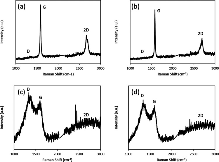
Based on the comprehensive characterization performed in the previous section, two fractions were selected as precursors for graphene synthesis: (a) the 450 °C TS-heptol (80:20)-eluted, as a highly aromatic and heteroatom-free fraction (F1), and (b) the 400 °C liquefaction distilled residue, as an aromatic fraction with high heteroatom content (F2). The F1 fraction has a H/C ratio of around 0.85, while that of the F2 fraction is around 1. In comparison to the known aromatic molecules, the H/C ratio of naphthalene is 0.81 and that of methylnaphthalene is 0.92. Thus the F1 fraction is more aromatic than methylnaphthalene. The goal was to test a hypothesis that F1 (∼1% heteroatom content) would generate higher-quality graphene than F2 (∼8% heteroatom content) through self-assembly by surface-mediated nucleation of the polyaromatic hydrocarbon cores in this fraction. The Raman spectra of graphene synthesized from both fractions on Ni and Cu substrates are shown in Figure 7. The main peaks in the Raman spectra of graphene are G, D, and 2D. G peak (1580 cm–1) is caused due to primary in-plane vibration due to the sp2 bonded carbon atoms and represents the graphitic characteristic of the material. The D peak (1350 cm–1) is caused due to out-of-plane vibrations attributed to the structural defects,32 representing the disorders in the sp2 hybridized graphene lattice. The 2D peak (2700 cm–1) is a second-order overtone of the D peak. The 2D mode is the strongest in monolayer graphene due to double resonance mechanism, and it falls in intensity with increasing number of layers.33,34
Figure 7.
Raman spectra of (a) F2 on Ni, (b) F1 on Ni, (c) F2 on Cu, and (d) F1 on Cu.
Interestingly, the films grown from F1 and F2 fractions had similar spectra on the Ni and Cu substrates. Both fractions formed defect-free multilayered graphene on Ni. The number of layers of graphene was calculated by the following equation35
where  is the ratio of the intensity
of the “G”
peak to that of the “2D” peak, and n is the number of graphene layers. The multilayered graphene formed
by both precursors on Ni had around 11 layers. The formation of multilayered
graphene instead of mono- or bilayered graphene can be attributed
to the high concentration of hydrogen compared to the carbonaceous
precursor.36 In contrast, amorphous carbon
was formed on copper with both fractions. Raman maps were obtained
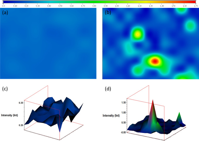
for graphene formed on Ni foils. Figure 8 shows the Raman map at a ratio of 2D/G intensities
for the graphene formed by F1 and F2 fractions. The F1 fraction formed a uniform layer of multilayered graphene throughout
the Ni foil, whereas the graphene formed by the F2 fraction was mostly multilayered graphene (blue) with
a few areas of monolayered graphene (red) and few-layered graphene
(green).
Figure 8.
Raman maps for 2D/G intensities ratio for the F1 fraction (a,c) and F2 fraction (b,d).
The growth mechanisms were different on Cu and Ni substrates. The carbon atoms were assimilated into the nickel substrate and then migrated to the surface by diffusion.37 On the contrary, the carbon growth on copper was a surface-controlled process.38 The hydrogen that was injected during the cleaning process of the substrates could readily diffuse into the copper, while it recombined with the nickel surface. The dissociative chemisorption of hydrogen competed with the dehydrogenation of hydrocarbons on copper,39 thus slowing down the reaction kinetics of graphene formation by blocking sites on the Cu surface. This led to formation of amorphous carbon instead of graphene, as shown by the wide blunt peaks in Figure 7c,d and lack of a 2D peak. In addition, carbon has a higher solubility in nickel,40 while hydrogen has a higher solubility in copper.39 Hence, the Ni substrate was found to help the healing of defects in graphene by continuously breaking and reforming nickel-carbon bonds around defects.41 Moreover, the temperature in the furnace 2 is sufficient to pyrolyze many of the functional groups of the F2 fraction. Therefore, multilayered graphene formed on Ni by both precursors was defect-free due to the high solubility of carbon, pyrolysis of the functional groups, and the healing effect of Ni. Since nickel can dissolve more carbon atoms and the carbon precipitation is a nonequilibrium process, it is very difficult to form large-area monolayered graphene.37 In case of copper, the interaction between the peripheral atoms of the fractions and copper is noncovalent, which cannot break C–C bonds.22 Thus, the clusters of molecules do not breakdown into smaller fragments on the copper substrate, and rather, the formation of the carbonaceous material is by self-assembly. Thus, molecular configuration and heteroatom content has a significant impact on the quality of graphene. Although the F1 fraction was highly aromatic and heteroatom-free, the constituent molecules vary substantially in planarity, in pendant substituents, and symmetry. This caused formation of amorphous carbon rather than graphene on the Cu substrate. Hence, the quality of graphene was governed by the substrate on nickel and by the precursor quality on copper.
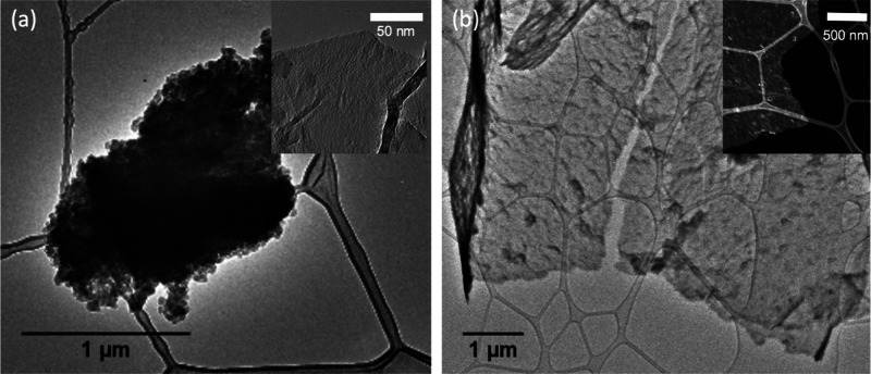
When deposited directly on lacey carbon-coated copper TEM grids, the two fractions generated very different graphene domains. Figure 9 shows the TEM micrographs of carbonaceous matter synthesized on these grids by CVD, where the insets were taken under higher magnification. F1 led to the formation of large multilayered graphene sheets on the scale of several micrometers. The high aromaticity of F1 and lack of heteroatoms allowed the aromatic sheets of the molecules to interconnect without the hindrance from heteroatoms or alkyl chains. While large sheets were generated, they were not completely pristine and consisted of some disorders and defects in the sheets, as seen in the TEM micrograph. In contrast, F2 led to formation of smaller aggregates of amorphous carbon. While there were some regions of much thinner sheet-like films seen in the inset, the overall product was very heterogeneous. During the synthesis, the F1 fraction was consumed almost completely (0.1 mg remaining), while 1.6 mg of the heavier components (higher boiling point than 400 °C) of F2 remained in the boat after graphene synthesis.
Figure 9.
TEM micrographs of carbonaceous matter grown directly on copper TEM grids by CVD using F2 (a) and F1 (b) fractions.
4. Conclusions
PRB coal from Wyoming was fragmented via a multistep process to obtain a liquid fraction that is highly aromatic, has a low boiling point, and contains no heteroatoms. The process consisted of DCL in tetralin under a nitrogen atmosphere at various temperatures, followed by Soxhlet extractions by heptane and toluene and liquid chromatography on silica gel using heptol solutions with different heptane/toluene ratios. The fractions thus obtained were characterized by 1H NMR, SAR-AD, TGA, and CHONS elemental analysis. One highly aromatic fraction, F1, with no heteroatoms (450 °C TS-heptol 80:20 eluted fraction) and one less aromatic fraction, F2, with higher heteroatom content (400 °C liquefaction distilled residue) were then used for graphene synthesis via CVD on Cu and Ni foils. Interestingly, both fractions yielded 11-layered defect-free graphene on Ni and graphite with high defects on Cu. Nickel led to the formation of defect-free multilayered graphene due to its high carbon solubility, pyrolysis of the functional groups, and defect healing properties. According to the Raman maps, the F1 fraction formed a uniform multilayered graphene and the F2 fraction formed mostly multilayered graphene with a few areas of monolayered and few-layered graphene. On the other hand, amorphous carbon was formed on copper due to the high solubility of hydrogen in copper, which competed with carbon. Paradoxically, the highly aromatic and heteroatom-free fraction formed amorphous carbon on copper since the molecules in this fraction contained random pendant substituents and did not share the same planarity and symmetry, creating defects. The F1 fraction generated micrometer-sized large multilayered graphene sheets by direct CVD on TEM copper grids, whereas in case of the F2 fraction, amorphous carbon was formed due to the presence of heteroatoms and significantly more alkyl substituents. Consequently, F2 formed smaller sheets that self-assembled into thick amorphous agglomerates.
Acknowledgments
The authors would like to thank the National Science Foundation (CAREER award #1351296) and the Carbon Engineering Initiative at the School of Energy Resources for funding this project. The authors would also like to thank Jenny Loveridge and Jerry Forney from the Western Research Institute for performing the SAR-AD and TGA tests and Dr. William Rice from the University of Wyoming for providing access to the Raman spectrometer.
Supporting Information Available
The Supporting Information is available free of charge at https://pubs.acs.org/doi/10.1021/acsomega.1c01614.
Yields of fractions obtained by multistep coal fractionation (PDF)
Author Present Address
∥ Anton Paar USA, Inc.—Western Regional Office, 2824 Columbia Street, Torrance, CA 90503.
Author Present Address
⊥ College of Chemistry and Chemical Engineering, Northwest Normal University, 967 Anning E Rd, Lanzhou, Gansu, China.
The authors declare no competing financial interest.
Supplementary Material
References
- Geim A. K.; Novoselov K. S. The rise of graphene. Nat. Mater. 2007, 6, 183–191. 10.1038/nmat1849. [DOI] [PubMed] [Google Scholar]
- Park S.; Ruoff R. S. Chemical methods for the production of graphenes. Nat. Nanotechnol. 2009, 4, 217–224. 10.1038/nnano.2009.58. [DOI] [PubMed] [Google Scholar]
- Balandin A. A.; Ghosh S.; Bao W.; Calizo I.; Teweldebrhan D.; Miao F.; Lau C. N. Superior Thermal Conductivity of Single-Layer Graphene. Nano Lett. 2008, 8, 902–907. 10.1021/nl0731872. [DOI] [PubMed] [Google Scholar]
- Service R. F. Carbon Sheets an Atom Thick Give Rise to Graphene Dreams. Science 2009, 324, 875. 10.1126/science.324_875. [DOI] [PubMed] [Google Scholar]
- Lee C.; Wei X.; Kysar J. W.; Hone J. Measurement of the Elastic Properties and Intrinsic Strength of Monolayer Graphene. Science 2008, 321, 385. 10.1126/science.1157996. [DOI] [PubMed] [Google Scholar]
- Novoselov K. S.; Geim A. K.; Morozov S. V.; Jiang D.; Zhang Y.; Dubonos S. V.; Grigorieva I. V.; Firsov A. A. Electric Field Effect in Atomically Thin Carbon Films. Science 2004, 306, 666. 10.1126/science.1102896. [DOI] [PubMed] [Google Scholar]
- Wu X.; Liu Y.; Yang H.; Shi Z. Large-scale synthesis of high-quality graphene sheets by an improved alternating current arc-discharge method. RSC Adv. 2016, 6, 93119–93124. 10.1039/c6ra22273k. [DOI] [Google Scholar]
- Emiru T. F.; Ayele D. W. Controlled synthesis, characterization and reduction of graphene oxide: A convenient method for large scale production. Egypt. J. Basic Appl. Sci. 2017, 4, 74–79. 10.1016/j.ejbas.2016.11.002. [DOI] [Google Scholar]
- Campos-Delgado J.; Botello-Méndez A. R.; Algara-Siller G.; Hackens B.; Pardoen T.; Kaiser U.; Dresselhaus M. S.; Charlier J.-C.; Raskin J.-P. CVD synthesis of mono- and few-layer graphene using alcohols at low hydrogen concentration and atmospheric pressure. Chem. Phys. Lett. 2013, 584, 142–146. 10.1016/j.cplett.2013.08.031. [DOI] [Google Scholar]
- Senthil Kumar E.; Sivasankar V.; Sureshbabu R.; Raghu S.; A. Kalaivani R. Facile synthesis of few layer graphene from bituminous coal and its application towards electrochemical sensing of caffeine. Adv. Mater. Lett. 2017, 8, 239–245. 10.5185/amlett.2017.7048. [DOI] [Google Scholar]
- Wang X.; Zhi L.; Müllen K. Transparent, Conductive Graphene Electrodes for Dye-Sensitized Solar Cells. Nano Lett. 2008, 8, 323–327. 10.1021/nl072838r. [DOI] [PubMed] [Google Scholar]
- Lii-Rosales A.; Han Y.; Evans J. W.; Jing D.; Zhou Y.; Tringides M. C.; Kim M.; Wang C.-Z.; Thiel P. A. Formation of Multilayer Cu Islands Embedded beneath the Surface of Graphite: Characterization and Fundamental Insights. J. Phys. Chem. C 2018, 122, 4454–4469. 10.1021/acs.jpcc.7b12533. [DOI] [Google Scholar]
- Zhang Y.; Zhang L.; Kim P.; Ge M.; Li Z.; Zhou C. Vapor Trapping Growth of Single-Crystalline Graphene Flowers: Synthesis, Morphology, and Electronic Properties. Nano Lett. 2012, 12, 2810–2816. 10.1021/nl300039a. [DOI] [PubMed] [Google Scholar]
- Kim K. S.; Zhao Y.; Jang H.; Lee S. Y.; Kim J. M.; Kim K. S.; Ahn J.-H.; Kim P.; Choi J.-Y.; Hong B. H. Large-scale pattern growth of graphene films for stretchable transparent electrodes. Nature 2009, 457, 706–710. 10.1038/nature07719. [DOI] [PubMed] [Google Scholar]
- Li X.; Cai W.; An J.; Kim S.; Nah J.; Yang D.; Piner R.; Velamakanni A.; Jung I.; Tutuc E.; Banerjee S. K.; Colombo L.; Ruoff R. S. Large-Area Synthesis of High-Quality and Uniform Graphene Films on Copper Foils. Science 2009, 324, 1312. 10.1126/science.1171245. [DOI] [PubMed] [Google Scholar]
- Cai W.; Zhu Y.; Li X.; Piner R. D.; Ruoff R. S. Large area few-layer graphene/graphite films as transparent thin conducting electrodes. Appl. Phys. Lett. 2009, 95, 123115. 10.1063/1.3220807. [DOI] [Google Scholar]
- Kim H.; Mattevi C.; Calvo M. R.; Oberg J. C.; Artiglia L.; Agnoli S.; Hirjibehedin C. F.; Chhowalla M.; Saiz E. Activation Energy Paths for Graphene Nucleation and Growth on Cu. ACS Nano 2012, 6, 3614–3623. 10.1021/nn3008965. [DOI] [PubMed] [Google Scholar]
- Wang D.; Vijapur S.; Botte G. Coal char derived few-layer graphene anodes for lithium ion batteries. Photonics 2014, 1, 251. 10.3390/photonics1030251. [DOI] [Google Scholar]
- Vijapur S. H.; Wang D.; Ingram D. C.; Botte G. G. An investigation of growth mechanism of coal derived graphene films. Mater. Today Commun. 2017, 11, 147–155. 10.1016/j.mtcomm.2017.04.003. [DOI] [Google Scholar]
- Mochida I.; Okuma O.; Yoon S.-H. Chemicals from Direct Coal Liquefaction. Chem. Rev. 2014, 114, 1637–1672. 10.1021/cr4002885. [DOI] [PubMed] [Google Scholar]
- Xu H.; Lin Q.; Zhou T.; Chen T.; Lin S.; Dong S. Facile preparation of graphene nanosheets by pyrolysis of coal-tar pitch with the presence of aluminum. J. Anal. Appl. Pyrolysis 2014, 110, 481–485. 10.1016/j.jaap.2014.10.017. [DOI] [Google Scholar]
- Wan X.; Chen K.; Liu D.; Chen J.; Miao Q.; Xu J. High-Quality Large-Area Graphene from Dehydrogenated Polycyclic Aromatic Hydrocarbons. Chem. Mater. 2012, 24, 3906–3915. 10.1021/cm301993z. [DOI] [Google Scholar]
- Batzill M. The surface science of graphene: Metal interfaces, CVD synthesis, nanoribbons, chemical modifications, and defects. Surf. Sci. Rep. 2012, 67, 83–115. 10.1016/j.surfrep.2011.12.001. [DOI] [Google Scholar]
- Alcañiz-Monge J.; Cazorla-Amorós D.; Linares-Solano A. Characterisation of coal tar pitches by thermal analysis, infrared spectroscopy and solvent fractionation. Fuel 2001, 80, 41–48. 10.1016/s0016-2361(00)00057-0. [DOI] [Google Scholar]
- Karaca F.; Morgan T. J.; George A.; Bull I. D.; Herod A. A.; Millan M.; Kandiyoti R. Molecular mass ranges of coal tar pitch fractions by mass spectrometry and size-exclusion chromatography. Rapid Commun. Mass Spectrom. 2009, 23, 2087–2098. 10.1002/rcm.4104. [DOI] [PubMed] [Google Scholar]
- Gargiulo V.; Apicella B.; Alfè M.; Russo C.; Stanzione F.; Tregrossi A.; Amoresano A.; Millan M.; Ciajolo A. Structural Characterization of Large Polycyclic Aromatic Hydrocarbons. Part 1: The Case of Coal Tar Pitch and Naphthalene-Derived Pitch. Energy Fuels 2015, 29, 5714–5722. 10.1021/acs.energyfuels.5b01327. [DOI] [Google Scholar]
- Herod A. A.; George A.; Islas C. A.; Suelves I.; Kandiyoti R. Trace-Element Partitioning between Fractions of Coal Liquids during Column Chromatography and Solvent Separation. Energy Fuels 2003, 17, 862–873. 10.1021/ef020267e. [DOI] [Google Scholar]
- Morgan T. J.; George A.; Alvarez P.; Herod A. A.; Millan M.; Kandiyoti R. Isolation of Size Exclusion Chromatography Elution-Fractions of Coal and Petroleum-Derived Samples and Analysis by Laser Desorption Mass Spectrometry. Energy Fuels 2009, 23, 6003–6014. 10.1021/ef9006966. [DOI] [Google Scholar]
- Li W.; Morgan T. J.; Herod A. A.; Kandiyoti R. Thin-layer chromatography of pitch and a petroleum vacuum residue. Relation between mobility and molecular size shown by size-exclusion chromatography. J. Chromatogr. A 2004, 1024, 227–243. 10.1016/j.chroma.2003.10.020. [DOI] [PubMed] [Google Scholar]
- Vasireddy S.; Morreale B.; Cugini A.; Song C.; Spivey J. J. Clean liquid fuels from direct coal liquefaction: chemistry, catalysis, technological status and challenges. Energy Environ. Sci. 2011, 4, 311–345. 10.1039/c0ee00097c. [DOI] [Google Scholar]
- Barraza J.; Coley-Silva E.; Piñeres J. Effect of temperature, solvent/coal ratio and beneficiation on conversion and product distribution from direct coal liquefaction. Fuel 2016, 172, 153–159. 10.1016/j.fuel.2015.12.072. [DOI] [Google Scholar]
- Saito R.; Hofmann M.; Dresselhaus G.; Jorio A.; Dresselhaus M. S. Raman spectroscopy of graphene and carbon nanotubes. Adv. Phys. 2011, 60, 413–550. 10.1080/00018732.2011.582251. [DOI] [Google Scholar]
- Simpson J. R.; Roslyak O.; Duque J. G.; Hároz E. H.; Crochet J. J.; Telg H.; Piryatinski A.; Walker A. R. H.; Doorn S. K. Resonance Raman signature of intertube excitons in compositionally-defined carbon nanotube bundles. Nat. Commun. 2018, 9, 637. 10.1038/s41467-018-03057-7. [DOI] [PMC free article] [PubMed] [Google Scholar]
- Wang X.; Christopher J. W.; Swan A. K. 2D Raman band splitting in graphene: Charge screening and lifting of the K-point Kohn anomaly. Sci. Rep. 2017, 7, 13539. 10.1038/s41598-017-13769-3. [DOI] [PMC free article] [PubMed] [Google Scholar]
- Das A.; Chakraborty B.; Sood A. K. Raman spectroscopy of graphene on different substrates and influence of defects. Bull. Mater. Sci. 2008, 31, 579–584. 10.1007/s12034-008-0090-5. [DOI] [Google Scholar]
- Liu L.; Zhou H.; Cheng R.; Yu W. J.; Liu Y.; Chen Y.; Shaw J.; Zhong X.; Huang Y.; Duan X. High-Yield Chemical Vapor Deposition Growth of High-Quality Large-Area AB-Stacked Bilayer Graphene. ACS Nano 2012, 6, 8241–8249. 10.1021/nn302918x. [DOI] [PMC free article] [PubMed] [Google Scholar]
- Li X.; Cai W.; Colombo L.; Ruoff R. S. Evolution of Graphene Growth on Ni and Cu by Carbon Isotope Labeling. Nano Lett. 2009, 9, 4268–4272. 10.1021/nl902515k. [DOI] [PubMed] [Google Scholar]
- Luo Z.; Lu Y.; Singer D. W.; Berck M. E.; Somers L. A.; Goldsmith B. R.; Johnson A. T. C. Effect of Substrate Roughness and Feedstock Concentration on Growth of Wafer-Scale Graphene at Atmospheric Pressure. Chem. Mater. 2011, 23, 1441–1447. 10.1021/cm1028854. [DOI] [Google Scholar]
- Losurdo M.; Giangregorio M. M.; Capezzuto P.; Bruno G. Graphene CVD growth on copper and nickel: role of hydrogen in kinetics and structure. Phys. Chem. Chem. Phys. 2011, 13, 20836–20843. 10.1039/c1cp22347j. [DOI] [PubMed] [Google Scholar]
- Yu Q.; Lian J.; Siriponglert S.; Li H.; Chen Y. P.; Pei S.-S. Graphene segregated on Ni surfaces and transferred to insulators. Appl. Phys. Lett. 2008, 93, 113103. 10.1063/1.2982585. [DOI] [Google Scholar]
- Wu P.; Zhang W.; Li Z.; Yang J. Mechanisms of Graphene Growth on Metal Surfaces: Theoretical Perspectives. Small 2014, 10, 2136–2150. 10.1002/smll.201303680. [DOI] [PubMed] [Google Scholar]
Associated Data
This section collects any data citations, data availability statements, or supplementary materials included in this article.


