Abstract
The mechanochemical synthesis of nanomaterials for catalytic applications is a growing research field due to its simplicity, scalability, and eco‐friendliness. Besides, it provides materials with distinct features, such as nanocrystallinity, high defect concentration, and close interaction of the components in a system, which are, in most cases, unattainable by conventional routes. Consequently, this research field has recently become highly popular, particularly for the preparation of catalytic materials for various applications, ranging from chemical production over energy conversion catalysis to environmental protection. In this Review, recent studies on mechanochemistry for the synthesis of catalytic materials are discussed. Emphasis is placed on the straightforwardness of the mechanochemical route—in contrast to more conventional synthesis—in fabricating the materials, which otherwise often require harsh conditions. Distinct material properties achieved by mechanochemistry are related to their improved catalytic performance.
Keywords: ball milling, catalyst synthesis, comminution, heterogeneous catalysis, mechanochemistry, nanomaterials
Mechanochemical routes enable the synthesis of different families of catalytic materials in a more sustainable and convenient way than classical methods. In addition, unusual properties may arise, leading to improved catalytic performance. The review covers the major achievements in the synthesis of catalysts assisted by mechanochemistry, discusses associated aspects, and provides perspectives.

1. Introduction
Catalytic processes are of key importance for the industrial manufacturing of valuable products from inexpensive raw materials (e.g., transportation fuels, bulk and fine chemicals, pharmaceuticals), and catalysts are the workhorses of these processes. [1] It is estimated that with a total sales price of catalytic materials of around 20 billion euro per year, the catalysis‐based industry can generate several trillion euro worth of goods per year, clearly highlighting the impact that catalysis has on our society. [2] Among the different kinds of catalysis, the chemical industry predominantly relies on heterogeneous catalysis (where a gas‐ or liquid‐phase reaction is performed over a solid catalyst) for several reasons, including ease of separation of the catalyst, its longevity, and compatibility with continuous operation. However, owing to their complex structure and limited knowledge of the active centres, the rational design of a solid catalyst is not straightforward. [3] This point becomes particularly important for the mass production of solid catalysts in a reproducible manner. As a result, catalyst synthesis has often been popularly regarded more as an art than science, in spite of the high level of technology reached in this field. Thus, not surprisingly, the multitude of studies focusing on the catalyst fabrication testifies the immense effort spent in mastering the rational synthesis of active, selective, and stable catalysts. [4]
Currently, only a few general routes exist for the production of catalysts on industrial scales that are sufficiently advanced to guarantee a reasonable level of control, namely precipitation, deposition‐precipitation, hydrothermal treatments, and impregnation; [5] to some extent, solid‐state reactions and fusing can also be included in this list. However, owing to their intrinsic nature, the solution‐based methods unavoidably lead to the production of a large amount of solvent waste. Besides, nitrate or chloride metal salts are often used as precursors, which can contribute to the formation of toxic gases during subsequent calcination steps and thus require additional efforts (e.g., neutralization) to avoid the release of these gases into the atmosphere. [2] Besides, wet‐chemistry methods, involving multiple steps, are often considered laborious and, eventually, tricky to scale‐up for a given formulation of the catalytic material. Moreover, solution processes and subsequent treatment steps at high temperatures often do not meet present ecological requirements, being energy‐demanding and, potentially, a source of harmful waste, as described above. Thus, the development of alternative synthetic protocols, which are more environmentally benign (i.e., involving no or limited liquid and gaseous waste), simple, cost‐effective, high‐yield, and scalable, is of high interest.
The development of alternative synthetic processes can be driven by superior properties of the resulting materials as well as by more favourable economic and/or ecological characteristics of the processes. The latter aspect is presently gaining increasing importance, since environmental problems and depleting energy reserves are becoming more and more critical. As a result, sustainable manufacturing processes, including those for catalysts synthesis, are considered particularly beneficial. [6] Mechanochemical methods, such as reactive extrusion and ball milling, have recently emerged as simple and effective synthesis routes to catalytic materials.[ 7 , 8 ] Although it is known since ancient times that pestle and mortar could be sufficient to induce some degree of chemical action, [9] the use of mechanochemistry expanded in the last century by means of newly designed high‐energy ball mills (see Section 2 for more details). [10]
At present, mechanochemistry is widely recognized as a branch of chemistry concerned with all the physicochemical transformations that are induced by the effect of mechanical forces. [11] The historical development of mechanochemistry is described in dedicated reviews.[ 10 , 12 ] Mechanochemistry has been intensively applied in metallurgy so that mechanochemical alloying represents on its own a consistent field of study. [13] However, recently, it has attracted researchers from many different directions, including organic, organometallic, inorganic chemistry, and materials engineering. [14] This review article will particularly focus on the latest progress in mechanochemistry for the synthesis of solid catalysts. In brief, the mechanochemical synthesis of catalysts concerns the preparation of materials with desired properties such as crystallization degree, morphology, phase composition, porosity, component distribution, and dispersion (in the case of nanostructured systems). [15] In addition to comminution and formation of new free surfaces, milling and grinding results in mechanical activation, often associated with an increase in reactivity due to stable changes in the structure of a given material. [16] Several important phenomena can occur both in the bulk and on the solid surface (e.g., accumulation of defects, amorphization, the formation of metastable polymorphs). Consequently, activity, stability, and deactivation of catalytically active sites can be significantly affected by the mechanical energy input. [7] Mechanochemical synthesis can therefore be very suitable for the preparation of effective catalysts, either as one step in a synthesis sequence or as the main stage of preparation. Besides, mechanochemistry has a number of potential advantages from an industrial point of view. Not only is it one of the least sophisticated and inexpensive technologies, but it represents an alternative preparation method, which could help to minimize the use and formation of hazardous materials and limit the energy requirements of the process. [17]
The aim of this review article is not to provide an exhaustive list of all studies on the topic but to draw the reader's attention to some remarkable cases where the mechanochemical approach has proven to be valuable as compared to conventional synthetic procedures. The structure of the review is based on the types of catalytic materials, organized as in the order: bulk materials (e.g., metal and metal oxides, multi‐component systems), either as catalyst or support, supported catalysts (supported metal and metal oxide nanoparticles, single‐atom catalysts), composite materials, and doped systems. Finally, we will briefly discuss the synthesis of more advanced materials, which are also useful as catalytic systems (e.g., hybrid materials, metal‐organic frameworks). The conclusion and outlook provide the authors’ view on the potential of mechanochemistry for catalyst synthesis and a perspective on mechanocatalysis (i.e., catalytic reactions directly in the ball mill).
2. General Aspects of Ball Milling
Before discussing the synthesis of different catalytic materials in more detail, key aspects of milling shall briefly be discussed, including widely used techniques in mechanochemistry. First, one should know that practical mechanochemistry mostly proceeds on a trial‐and‐error basis because a comprehensive rational framework is not yet accessible. Still, the vast number of case studies currently available allows some general and meaningful conclusions. [13]
On the most basic level, a mechanochemical reaction (via ball milling) consists of just a few steps. Initially, the milling vessel (also referred to as grinding jar or milling vial) is loaded with the milling media (i.e., balls) and reactant(s) in the required order. This operation should conveniently be carried out under a protective atmosphere (e.g., inside atmosphere‐controlled glove boxes) when reactive powders are employed, to avoid their oxidation and contamination (see Section 3.1). Process control agents are sometimes added to the milling mixture, mostly to minimize particle agglomeration by acting as lubricants or surfactants. [18] Then, the grinding jar is sealed and secured with clamps inside the mill, where the milling is carried out for the desired time at an appropriate milling frequency. Finally, the milled material is recovered, possibly again in a glove box. Optionally, one last step to remove possible contaminants from the milling materials is required. Despite the apparent simplicity of the method, several factors, which can strongly influence the result of the process, have to be taken into account.
First, the type of milling device used is critical. At present, various types of ball mills are available, from laboratory scale (vessel size in the 1–500 mL range) to industrial‐scale (vessel size of several hundred litres and higher), useful for diverse applications. Most up‐to‐date information concerning different types of mills and corresponding scalability are discussed in a recent publication. [19] For simplicity, only two types of mills will be described here, namely shaker (or mixer‐type) mills and planetary mills, which are the most common benchtop laboratory mills. In fact, most of the studies discussed in this review were conducted with one of these mill types. In a shaker mill, the jar containing the sample and grinding balls typically swings back and forth on a curved trajectory (Figure 1 a). For such a design, substantial impact‐related forces result from small amplitudes at high oscillation frequency. In a planetary mill, the vials are instead arranged on a rotating support disk, where a drive mechanism also causes them to simultaneously rotate around their own axes (Figure 1 b). Since the vials and the supporting disk rotate in opposite directions, the centrifugal forces alternately act in like and opposite directions. This will cause the grinding balls to run down the inside wall of the vessel (exerting friction) and then suddenly being projected and collide against the opposite side (exerting impact). [13] Finally, the impact and shear between balls, where the powder can also be found, contribute to the overall mechanical stress exerted on the material. In planetary mills, therefore, a combination of friction, shear, and impacts is generated, in contrast to shaker mills where impacts dominate (Figure 1 c).
Figure 1.
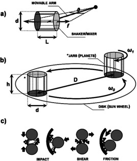
Schematic representation of selected types of ball mills (appearance and mode of action) for high‐energy ball milling. In a shaker mill (a), the grinding jar energetically swings back and forth on a curved trajectory with a given amplitude (θ) and frequency (f). The length (L) and diameter (d) of the milling capsule may decide for the motion of the balls in action (e.g., intensity and frequency of the collisions). In a planetary mill (b), the jars revolve around the centre of the sun wheel (ω0, is the nominal angular velocity) while rotating around their own axis (the corresponding angular velocity, ω1, being not necessarily equal to ω0). In this context, the height (h) and diameter (d) of the vials are important. While collision or impact‐related type of stress is most dominant in a shaker/mixer mill, a combination of shear, friction, and impacts (c) is generated in planetary‐type mills.
Selecting an appropriate material for grinding jar and medium is also of crucial importance. In most cases, the construction material of the grinding jar and media differs from that of the powder being processed. As a result, the milled material will likely be contaminated to some extent by abrasion from the mill. The extent of abrasion depends on a number of factors, such as the relative hardness of the milled powder, wear resistance of technical materials, ball‐to‐powder weight ratio, and the energy regime explored. On the other hand, if the two materials are the same, then proper precautions may be required to compensate for the additional elements incorporated into the powder. Common materials used to manufacture grinding tools include different types of steel (e.g., hardened steel, tempered steel, stainless steel) and tungsten carbide. Other materials may be used for specialized purposes, such as sintered corundum, yttria‐stabilized zirconia, agate, and Si3N4. One should keep in mind that it is not the nominal designation of the grinding equipment that is crucial, but the exact formulation, as often additional components are used, which could be detrimental for the application of mechanochemically processed powders, especially in catalysis. For instance, the iron in the steel (already active in numerous catalytic reactions) could be alloyed with several other metals (e.g., Ti, Cr, Mn, Ni, Cu, and Mo), which are likely found in milled powders.[20. 21]
Tungsten carbide tools could contain varying amounts of Co or Ni as binders. [22] Ceramics based on corundum or stabilized zirconia phases will possibly include a combination of different metal oxides in small amounts to favour sintering, as for those based on Si3N4.[ 23 , 24 , 25 ]
The number of grinding balls used and their size (or size distribution) are other important factors. This choice is typically guided by the aim of achieving good productivities in the shortest possible time. To this end, high ball‐to‐powder weight ratios usually are preferred, as the number of collisions per unit time increases and more energy is transferred to the powder particles, provided that the extent of filling of the milling jar does not limit the free movement of the balls. [26] It is also known that a large size (and high density) of the grinding medium will contribute to more energetic collisions, whereas smaller (and lighter) balls will produce intense frictional action. However, more helpful would be to use a combination of smaller and larger balls to randomize their motion and guarantee that the powder will be evenly processed. For planetary mills, it was noted that the balls tend to roll along a well‐defined trajectory instead of hitting the surfaces randomly. Thus, a combination of experimental conditions can hardly be established a priori, particularly when the mechanochemical transformation does not only consist in mere comminution and mixing but implies a more complex interaction between the solid reactants so that stringent energetic requirements come into play.
The duration and intensity of the treatment are additional variables that one must take into account. Broadly, the time required to finalize the process depends on the precise combination of experimental parameters in use, and it differs from case to case. At any rate, milling times should be optimized to be as short as possible as the level of contamination tends to increase with time. Besides, undesired phases are more inclined to form after prolonged milling, partly because of the rise in temperature usually observed under these circumstances. The temperature rise in the vial could indeed lead to increased diffusivity and equilibration effects, which may or may not be overall advantageous for the process (e.g., homogenization is favoured at the expense of crystallinity and phase relative stability). To avoid this, it is usually recommended to introduce sufficiently long breaks between intense milling sessions to bring the temperature back to lower values, especially when operating with planetary‐type mills. [27] Alternatively, it is possible to perform the mechanochemical reaction under more controlled conditions by adapting the overall set up to specific requirements. Operation at temperatures ranging from −196 °C to 150 °C was achieved in grinding jars equipped with appropriate temperature control (e.g., a cryostat or a heating box).[ 28 , 29 , 30 ] Moreover, the grinding jar can be modified for processing under a controlled atmosphere, both in static (pressure)[ 31 , 32 , 33 ] and dynamic (flow‐through) conditions,[ 34 , 35 , 36 , 37 , 38 ] which remarkably extends the field of application of mechanochemistry.
3. Metal and Metal Oxide Nanoparticles
Nanoparticles (NPs) play a key role in many fields and have found widespread applications. [39] They are broadly defined as particles that are 1 to 100 nm in diameter, and they often possess unique properties. The investigation of NPs thus has attracted the interest of scientists and engineers from different branches of science. Metal NPs (MNPs) and metal oxide NPs (MONPs) are two of the most important subclasses of NPs. Among the various fields of application, M(O)NPs (particularly in the supported form) are very interesting in catalysis, as their intrinsic higher surface‐to‐bulk ratio guarantees maximum utilization of the often precious components. [40] The NPs are synthesized mainly by wet‐chemistry and thermal methods, including precipitation, sol‐gel synthesis, hydrothermal synthesis, spray drying, annealing, and flame pyrolysis, to mention only a few.[ 39 , 41 ] The mechanochemical route, which is becoming more and more popular,[ 14 , 15 , 37 , 42 ] already proved to be advantageous over conventional methods as a low‐waste or even waste‐free process. Besides, the availability of high‐energy ball milling devices (see Section 2), which typically have 1000 times higher impact energy than conventional ball mills, enable access to sub‐micrometre to nanometre‐sized solid particles.[ 43 , 44 ] This is a notable advancement compared to conventional milling devices, which indeed already allowed access to the domain (crystallite) size in the nanometre range, but not to particle sizes of the same order of magnitude, as they typically lie in the micrometre range.[ 37 , 45 ] In any case, the reports on the mechanochemical synthesis of nanoparticles should be interpreted with caution. Sometimes the size of the nanoparticles is only analysed by XRD, where the reflection broadening indicates the size of coherently scattering domains. However, the actual particles might be substantially bigger, and the particles may be composed of several such domains. Inner boundaries between domains are typically not relevant for catalysis; it is the outer surface on which a catalytic reaction occurs. Thus, to judge the relevance of a synthetic method for catalysis, the particle size should be analysed by techniques that give information on the available surface area (i.e., electron microscopy or sorption methods).
3.1. Metal nanoparticles
The mechanochemical synthesis has been demonstrated for the preparation of different metal NPs, including iron,[ 46 , 47 ] copper,[ 48 , 49 ] nickel, [50] silver,[ 51 , 52 ] gold, [53] and palladium. [53] Besides, bimetallic NPs, such as Fe‐Cu, [54] Fe‐Pt, [55] Pd‐Ag, [56] and Cu‐Ag, [57] have also been fabricated by mechanochemistry. The synthesis of iron and copper NPs involves simple grinding of micrometre‐sized metal powders at room temperature under an inert gas atmosphere or air. Ball milling of iron powder under an inert atmosphere in a vibratory mill for 30 h and in air in a planetary mill for 10 h led to the production of Fe NPs of 2–4 nm (NP size from TEM images) and 11 nm (crystallite size from XRD), respectively.[ 46 , 47 ] Longer milling in air has been shown to lead to the formation of the iron oxide phase. [47] Both dry and wet (using toluene as reducing medium and solvent) grinding were reported for the synthesis of Cu NPs.[ 48 , 49 ] Grinding in toluene in a planetary mill for 40 h led to the formation of Cu NPs down to 21 nm (crystallite size from XRD).[ 48 , 49 ] Preparation of ultrapure Ag NPs with particle size in the 4–8 nm range (derived from TEM analysis) in large quantities by cryomilling from silver powder has been reported (i.e., milling at liquid N2 temperature, −196 °C) under a protective Ar atmosphere. [51] Friščić and co‐workers have demonstrated a bottom‐up mechanochemical approach for the synthesis of Ag, Au, and Pd NPs.[ 52 , 53 ] It involves the ball milling of metal salts or complexes at room temperature in the presence of Kraft lignin powder (a biomass waste). Lignin serves as a matrix for the formed NPs and as a reducing agent enabling the generation of Ag, Au, and Pd in metallic form. It is important to note that in the synthesis of MNPs their stability, namely their tendency to be oxidized, is a crucial factor. In order to avoid unwanted oxidation, grinding under an inert environment or even under reducing conditions is required, as noted in some of the above examples. This stability aspect becomes even more important in the catalytic reaction itself, as the NPs can get oxidized under the reaction conditions. Besides, self‐standing NPs might be susceptible to sintering/agglomeration under realistic reaction conditions. Thus, MNPs are usually stabilized on a support. The synthesis of supported NPs is discussed in the sections below.
3.2. Metal oxide nanoparticles
Metal oxide NPs also have important applications in catalysis, primarily because they can act both as active phases (i.e., bulk or self‐supported catalyst) and as supports. High surface area is a crucial property of a catalytic material as it allows the exposure of more active sites and thereby to achieve higher yields. Due to its intrinsic features, mechanochemical processing, in most cases, facilitates particle size reduction. However, a more intriguing aspect is that the mechanochemical synthesis also allows the fabrication of metal oxide phases that are generally difficult to obtain otherwise. Besides, the features of the resulting materials, such as nanocrystallinity, surface areas, and defect concentration, can surpass those of their conventionally synthesized counterparts.
TiO2, ZrO2, γ‐Al2O3, and SiO2 are among the most often used supports in heterogeneous catalysis, owing to their reasonably high surface area and their thermal and mechanical stability. Among these, nanoparticulate forms of rutile TiO2, tetragonal and cubic ZrO2, and α‐Al2O3 (corundum) are very difficult to obtain as they require lengthy annealing at very high temperatures, leading to low final surface areas. Therefore, despite being particularly appealing for catalysis due to their excellent thermal and chemical stability, these forms are not often applied. In contrast, mechanochemical grinding has been shown to provide easy access to the nanoparticulate form of these phases by top‐down (involving comminution and phase transformation) [58] and bottom‐up (e.g., via redox and dehydration reactions induced during grinding) [42] strategies (Figure 2).
Figure 2.
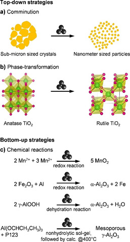
Examples of mechanochemical syntheses of metal oxide nanoparticles by top‐down (involving (a) particle comminution and (b) phase‐transformation),[ 58 , 59 , 60 , 61 ] and bottom‐up (involving (c) chemical reactions, e.g., redox and dehydration reactions)[ 42 , 62 , 63 , 64 ] strategies. Atom colours in (b): Ti, green; O, pink.
A top‐down approach was successful in the synthesis of rutile TiO2 nanoparticles. [58] It involves the ball milling of bulk TiO2‐rutile at room temperature for 24 h, leading to a crystallite size of about 6 nm in diameter, as indicated by XRD analysis (Figure 3 a). Surface characterization of the ball‐milled sample by XPS indicated a slight reduction of the surface, which was attributed to a reduced O coordination of titanium at the surface of the TiO2 NPs. This altered redox character might be useful in catalysis. Another route to rutile TiO2 is based on a phase transformation approach.[ 37 , 60 ] Herein, the anatase form of TiO2 was ball milled in a planetary mill at 220 rpm for 40 h in oxygen, air, or nitrogen atmosphere. Ball milling induced the phase transformation of anatase to rutile (Figure 3 b). Intriguingly, the rate of phase transformation from anatase to rutile has been found to increase with a decrease in the oxygen partial pressure in the milling capsule. Such behaviour seemed to relate quite reasonably with a reduced concentration of oxygen vacancies in the TiO2 lattice upon ball milling, suggesting that the defectiveness of the material can play a role in the phase transformation of metal oxides. The appearance of intermediate phases, such as srilankite and brookite, has also been reported. The preparation of tetragonal and cubic ZrO2 nanoparticles was similarly achieved through the phase transformation route.[ 65 , 66 ] Besides, several other redox‐active metal oxides, which could serve as catalysts, have been successfully fabricated in a nanocrystalline form via mechanochemistry. Top‐down synthesis of V2O5 nanoparticles via comminution and bottom‐up synthesis of MnO2 by redox reactions constitute interesting examples in this category (Figure 2 a, c).[ 58 , 63 ]
Figure 3.
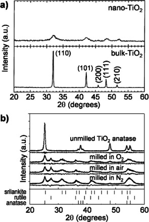
XRD patterns of titania for the preparation of rutile TiO2 nanoparticles by (a) comminution of micron‐sized preformed rutile TiO2 particles (Adapted with permission from ref. [58], Copyright 2003 Elsevier Science B.V.) and (b) phase transformation of anatase TiO2 (Adapted with permission from ref. [60], Copyright 2004, Elsevier).
Various mechanochemical strategies have been reported for the synthesis of α‐Al2O3 in nanoparticulate form, owing to its high technological relevance.[ 42 , 67 , 68 ] An early attempt consisted of the phase transformation of γ‐Al2O3 to α‐Al2O3.[ 59 , 61 ] In these studies, nanocrystalline γ‐Al2O3 (S BET >120 m2 g−1) was ball milled at room temperature, alternately in air or inert atmosphere, for a duration of up to 12 h, which led to the formation of α‐Al2O3 (Figure 4 a). However, a severe decrease in the surface area was observed, presumably due to extensive cold‐welding or particle agglomeration upon ball milling (Figure 4 b). Still, starting from γ‐Al2O3 with a surface area of about 200 m2 g−1, α‐Al2O3 with surface areas in the range of 40–90 m2 g−1 was achieved. Although this moderately high surface area for corundum is also appealing for catalytic applications, it is unattractive for large‐scale production due to the need for a starting material with a high surface area. Top‐down strategies, involving either dry or wet ball milling, were also investigated for the synthesis of corundum in nanoparticulate form from large crystals of α‐Al2O3 (prepared by conventional high‐temperature annealing, >1150 °C).[ 69 , 70 , 71 ] This method also led to the formation of corundum NPs with surface areas well above 100 m2 g−1 and particle sizes as small as 20 nm. However, high hardness of α‐Al2O3 induced significant abrasion of milling vessels and media, eventually leading to severe contamination.
Figure 4.
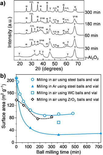
(a) XRD patterns showing the evolution of the corundum phase by phase transformation of γ‐Al2O3 (Adapted with permission from ref. [59], Copyright 2015, Elsevier). (b) Changes of the surface area during ball milling as a function of milling time (○,▴,□: Adapted with permission from ref. [59], Copyright 2015, Elsevier. and ◊: from ref. [61], Copyright 1993 Materials Research Society). Symbols in (a) indicate crystalline phases: γ, γ‐Al2O3; α, α‐Al2O3.
Recently, Pu et al. reported another approach based on a redox reaction between metallic aluminium and α‐Fe2O3 induced in a planetary ball mill. [62] In this process, the aluminium powder was ball milled with α‐Fe2O3 (Al : Fe=1) for 20 h, which caused the oxidation of aluminium with iron oxide to form α‐Al2O3 embedded in a metallic iron matrix. The iron matrix was then removed by corrosion with a concentrated mineral acid. In particular, it includes three consecutive room temperature treatments of the Fe‐matrix containing corundum NPs, using 12 m HCl acid for 10 h, followed by hydrothermal treatment using 4 m HCl acid at 120 °C in a sealed autoclave for 10 h. The final nanoparticulate α‐Al2O3, having an average particle size lower than 10 nm, was achieved by refined fractionated coagulation using aqueous HCl (Figure 5).
Figure 5.
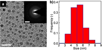
(a) TEM image and (b) particle size distribution for α‐Al2O3 nanoparticles obtained by the redox reaction between α‐Fe2O3 and Al (Figure 2 c, second reaction. Scale bar, 20 nm; inset: SAED pattern, scale bar, 5 nm−1). Adapted with permission from ref. [62] under CC BY 4.0.
A simple approach was reported very recently by Amrute et al., [42] which had been, to some extent, explored by Tonejc et al. already two decades ago. [72] It involves the mechanochemical dehydration of boehmite at room temperature to produce α‐Al2O3 with an average particle size of ca. 15 nm (from TEM analysis) and BET surface areas (S BET) up to 140 m2 g−1. In this process, a boehmite powder is simply ball‐milled in a shaker mill for 3 h at room temperature. This leads to the full conversion of boehmite into a mixture of α‐Al2O3 (major fraction) and α‐AlOOH (diaspore, minor fraction) (Figure 6 a). This mixture is then calcined in static air at 550 °C to obtain high purity α‐Al2O3 in the nanocrystalline form (see the green pattern in Figure 6 a), with surface areas in the range of 110–140 m2 g−1. Alternatively, prolonged ball milling (12 h) also resulted in phase‐pure α‐Al2O3‐nanopowder (see maroon pattern superimposed on the green pattern in Figure 6 a). The results suggested that water molecules in the boehmite structure play a crucial role in generating and stabilizing the α‐Al2O3 NPs. Moreover, the boehmite‐to‐corundum conversion is shown to be accompanied by severe microstructural rearrangements (Figure 6 b) and might involve the formation of rare mineral phases as intermediates, such as diaspore and tohdite. In this study, the energetics of the boehmite‐to‐corundum transformation was described by quantum‐chemical calculations. At standard state (T=25 °C, P=1 bar), γ‐AlOOH is a more stable phase than α‐Al2O3 irrespective of the surface area (black and green lines, Figure 6 c). The calculation considered the role of possible vacancies/defects formed by milling impacts. Given the dehydration reaction, water vacancies were assumed as the primary defects, among others, and are suggested to increase the surface energy of boehmite. This reverted the stability order, making α‐Al2O3 more stable than γ‐AlOOH above S BET of 108 m2 g−1 (blue line, Figure 6 c). Thus, vacancies/defects formed during milling have a tremendous impact on the outcome of a mechanochemical transformation, as also seen above for the case of titania. Additionally, the desorbed water can hydroxylate the surface of formed α‐Al2O3 and thus lower the surface energy of α‐Al2O3 even more (pink line, Figure 6 c), eventually making it the most stable phase in the milling system. Interestingly, the synthesis could be flexibly adapted to other milling devices (e.g., planetary mill). Besides, it proved to be compatible with different grinding jars and media. Finally, the boehmite dehydration process in the ball mill was recognized as tolerant of the properties of the boehmite precursors. For instance, boehmite with different initial S BET (e.g., 10, 50, or 80 m2 g−1) was readily converted to α‐Al2O3 with S BET of 110–140 m2 g−1. The process is currently being scaled‐up to a several 100 grams scale, with prospects of larger capacities in the near future. [73]
Figure 6.
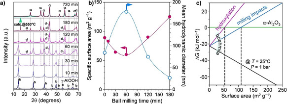
(a) XRD patterns showing development α‐Al2O3 phase from boehmite by dehydration induced during ball milling, (b) surface area and hydrodynamic diameter of versus milling time, and (c) free energy change as a function of surface area for the standard state (T=25 °C, P=1 bar) and considering effects of milling impact and hydroxylation. Adapted with permission from ref. [42], Copyright 2019 The Authors. Symbols in (a) indicate crystalline phases: γ, γ‐Al2O3; α, α‐Al2O3; b, γ‐AlOOH (boehmite); d, α‐AlOOH (diaspore).
As mentioned above, high‐surface‐area α‐Al2O3 is a highly valuable material for catalysis, among other applications, because it can provide stable support for active phases. To explore its potential, a recent study analysed its hydrothermal properties under relatively harsh conditions in comparison with a conventional low‐surface area α‐Al2O3 and widely used γ‐Al2O3 support. [74] Expectedly, γ‐Al2O3 severely degraded to boehmite already after a 5 h hydrothermal (HT) test (H2O:Al=50, at 150 °C in a sealed autoclave) as clearly shown by XRD analysis of samples after HT treatment (Figure 7 a). In contrast, conventional α‐Al2O3 (α‐Al2O3‐conv.) fully retained its corundum phase after the HT treatment. Interestingly, nanocrystalline α‐Al2O3 prepared by ball milling and followed by calcination at 550 °C (α‐Al2O3‐bm‐550, S BET=120 m2 g−1) only showed a slight degradation to boehmite after such 5 h HT test, whereas the sample calcined at 800 °C after ball milling (α‐Al2O3‐bm‐800, S BET=72 m2 g−1) evidenced outstanding robustness as it retained its corundum phase entirely even after 20 h of continuous HT treatment (Figure 7 b). The difference in the stability of γ‐Al2O3 and corundum was explained based on solid‐state NMR spectroscopy and surface cation coordination analysis. It was suggested that low‐coordinated surface tetrahedral Al species, usually in an amount of 20–70 % on γ‐Al2O3, are prone to undergo chemical weathering reaction. Since α‐Al2O3 is composed exclusively of octahedral Al (AlO) sites and the occurrence of low coordination AlO (especially, low stability (III)AlO) is less common than higher coordination AlO (more robust), corundum much better preserves its structure under hydrothermal conditions. Hence, mechanochemically‐derived α‐Al2O3‐bm‐800 offers a stable support material with a reasonably high surface area. This led to its application for the synthesis of a robust cobalt‐based Fischer–Tropsch synthesis (FTS) catalyst (Co/α‐Al2O3‐bm‐800). [74] The latter catalyst showed significantly more activity than the conventional α‐Al2O3‐based system, matched the activity and selective level of the benchmark γ‐Al2O3‐based catalyst, and remained stable over 250 h on stream (Figure 7 c, d).
Figure 7.
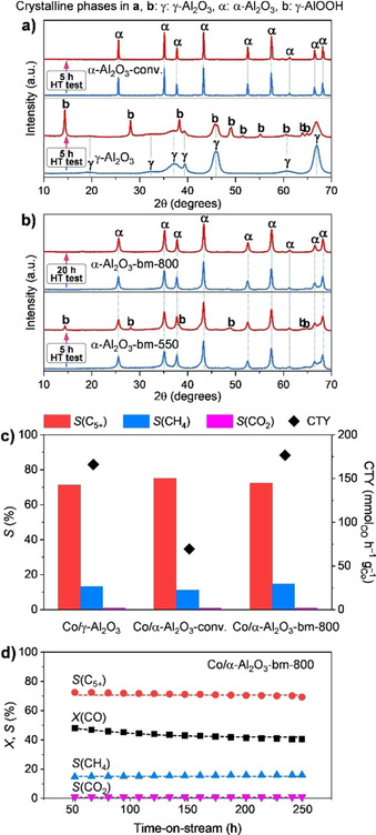
XRD patterns of (a) γ‐Al2O3, conventional α‐Al2O3, and (b) high surface area α‐Al2O3 derived by ball milling (bm) before and after hydrothermal (HT) treatment at 150 °C for 5 or 20 h. (c) Pseudo‐steady state cobalt‐time‐yield (CTY, diamonds) and product selectivity (S) (bars) in FTS over alumina‐supported cobalt catalysts at 50±2 % CO conversion (X(CO)). (d) Time‐on‐stream performance of Co/α‐Al2O3‐bm‐800. Conditions: mass of Co=100 mg, H2/CO=2, T=210 °C, P=20 bar, WHSV=16–19 h−1. Adapted with permission from ref. [74], Copyright 2020 American Chemical Society.
A mechanochemical route is also suitable for the synthesis of mesoporous alumina (γ‐Al2O3). [64] The process is referred to as mechanochemical nonhydrolytic sol‐gel‐strategy (Figure 8). It involves the ball milling of aluminium isopropoxide, a soft template (Pluronic triblock copolymers such as Pluronic P123 and Pluronic F127 and polyethylene glycol, PEG), and optionally cetyltrimethylammonium bromide (CTAB), at a high frequency (30 Hz) in a shaker mill for 60 min. The milling leads to an assembly between aluminium isopropoxide and P123 micelles. The composite is then washed with ethanol and dried at 40 °C under vacuum before being finally calcined at 400 °C. This method is reported to provide mesoporous alumina having an exceptionally high surface area (about 650 m2 g−1) and mesoporous characteristics (average pore diameter of 4.2 nm). The use of other soft templates (PEG or F127) or surfactant (CTAB) was also described, but they were found less effective than P123 itself. Moreover, the synthesis of mesoporous carbons was also achieved by a mechanochemical approach. The finding of Zhang et al. that ball milling can sustain the coordinative cross‐linking polymerization of tannin with divalent metal ions (as metal acetates, e.g., Zn2+, Ni2+, and Co2+) in the presence of a template (e.g., Pluronic triblock copolymers) lead to the synthesis of various ordered mesoporous carbons. [75] Indeed, the use of templates with different compositions simply enabled the synthesis of mesoporous carbons with tuneable pore sizes, ranging from 4 to 10 nm, after carbonization of the gel nanocomposite. [76] These results clearly point at the potential of mechanochemistry as a nanostructuring tool, that is, by assisting the appearance of mesoporosity in a solid material.
Figure 8.

Scheme for the synthesis of mesoporous Al2O3 (meso‐Al2O3) via the mechanochemical nonhydrolytic sol‐gel (NHSG) method. Adapted with permission from ref. [64]. Copyright 2019 American Chemical Society.
4. Supported Catalysts: From Nanoparticles to Single‐Atom Species
Under the best conditions, the activity of a solid catalyst relies on the available amount of active sites per unit mass of the active component. Therefore, a higher activity per unit mass is generally achieved over smaller nanoparticles (NPs). However, NPs alone are not stable as they are usually prone to sinter under practical reaction conditions. [77] To avoid this, the active phase is normally dispersed on a solid material, commonly referred to as “support” or “carrier”, which can limit the sintering of NPs, by means of mere dilution, spatial separation, or through various kinds of interactions with the active metal NPs. Thus, the dispersion of active components on its surface or within the pores allows more active centres to participate in the reaction, ultimately resulting in improved activity per mass of active—and often expensive—metal loaded. Thus, the use of a support material helps to reduce the use of expensive active phases (i.e., making the catalyst more cost‐effective). Finally, the support may also contribute to improved mechanical strength and thermal stability.
A plethora of different methodologies is available for the synthesis of supported catalysts. Nevertheless, only a few of them have found large‐scale applications due to understood limitations associated with their scale‐up. As a result, only two preparation methods are currently widely applied in the industry, namely precipitation and impregnation. [2] However, these methods unavoidably involve several synthetic steps and post‐synthetic treatments. Therefore, they are often associated with a high amount of solvent waste. Also, a high degree of precision is needed during the various stages of the preparation to reproduce the synthesis of catalysts with desired properties. Finally, solution‐based or high‐temperature processes are often not fully compatible with present‐day energy and ecological requirements.
In contrast, mechanochemistry can promote solid‐state reactions under relatively mild conditions, with only a nominal amount of solvent or even without the need for any additives. [78] Additionally, the mechanochemical synthesis often provides quantitative yield in relatively short reaction times. In cases where the desired product cannot be obtained by grinding alone, temperature decrease and easy interaction of phases during further treatments (e.g., calcination, hydration, sorption, reduction) to facilitate reaction are at least favoured by the mechanical treatment. As a result, mechanochemically‐assisted processes tend to be cost‐effective and are highly beneficial for large scale applications, either as a step or as a sole synthetic strategy. [17] Finally, this approach has also been shown to produce materials that have different activities and selectivities as compared to conventionally prepared catalysts. This will be extensively discussed in the following sections, focusing mostly on the advantageous use of mechanochemistry to prepare finely dispersed and nanosized supported systems. In particular, two prominent classes of supported catalysts, namely supported metal NPs and supported metal oxide NPs, will be discussed in detail.
4.1. Supported metal nanoparticles
Several recent studies were targeted at developing solvent‐free preparations of supported metal catalysts based on simple mechanochemical processing, involving ball milling of an adequate metal precursor and target support, accompanied or followed by a reduction step. The work of Li et al.[ 79 , 80 ] concerning the development of a facile and potentially scalable method to deposit metal nanoparticles on carbon nanotubes constitutes one of the first notable examples. This process, also known as “decoration”, is of particular interest in catalysis due to the unique properties of the resulting metal‐carbon nanohybrid materials. [81] Multi‐walled carbon nanotubes (MWCNTs) and other carbonaceous or graphite‐like supports were successfully decorated with metal nanoparticles, relying on a one‐step synthetic protocol based solely on mechanochemical grinding. Thus, ball milling alone was sufficient to disperse the metal precursor and induce subsequent reduction/deposition of metal nanoparticles. The decoration of MWCNT and other types of supports with Ag NPs was investigated in detail. [79] In a typical experiment, MWCNT powder and silver acetate were firstly added to a 20 cm3 zirconia milling vial (vibratory mill fit) and then mixed for the desired time, using two 13 mm grinding balls at 17–18 Hz. Ball milling for 10 min was indicated as a good compromise to get a satisfying degree of mixing and, at the same time, preserve the carbon nanotubes structure. It was indeed observed that prolonged milling times could cause damage to the carbon nanotubes, in particular, fragmentation and shortening. [82] After the mechanochemical step, the solid mixture was heated under an inert atmosphere for a few hours above the decomposition temperature of the silver(I) acetate (276 °C), which led to the formation of metal nanoparticles on the surface of the carbon nanotubes (Figure 9 a). However, in the course of the study, it was found that the mechanochemical energy input on its own was sufficient to induce a certain degree of salt‐to‐metal conversion (63 % according to the powder XRD studies) and, thus, the formation of metal nanoparticles (Figure 9 b). [80] A consistent number of relatively large silver acetate nanocrystals accounted for the residual fraction of non‐reacted salt. Although the mechanochemical energy from ball milling resulted in a similar outcome, the salt decomposition seemed to occur differently than during thermal decomposition. Presumably, large salt crystals are at first comminuted and thus turned into nanosized particles, more prone to graft onto the carbon nanotubes surface. Then, the residual mechanical energy, adsorbed by the thermally conductive nanotube surface, is transferred to the salt nanoparticles, allowing their fast decomposition. Subsequently, a relatively narrow distribution of very small Ag nanoparticles (<5 nm), much smaller than those obtained via exhaustive thermal decomposition (30 nm), was obtained. The thermally conductive nature of the support appears to be crucial to induce the salt‐to‐metal conversion during milling. This is further supported by the experiments in which the acetate salt was ball‐milled alone or in the presence of thermally insulating supports (e.g., silica‐alumina ceramic microspheres) as only a negligible amount of metallic Ag formed over time. Conversely, when substrates such as single‐walled carbon nanotubes (SWCNTs), expanded graphite (EG), and hexagonal boron nitride (h‐BN) were employed, the salt‐to‐metal conversion varied according to both the thermal conductivity and the surface area available for the deposition of metal nanoparticles, following the order: SWCNTs>MWCNTs>EG>h‐BN. In any case, full conversion can be finally achieved with longer milling times. Overall, this study presented an interesting mechanochemical route for the rapid formation of metal nanoparticles on various supports. An additional thermal treatment was suggested to be beneficial but was essentially not necessary. Other metal salts also showed a reactivity similar to silver(I) acetate and proved to be suitable alternative metal precursors. For instance, Pd nanoparticles formed when palladium(II) acetate was subjected to ball milling in the presence of carbon nanotubes. The resulting material notably exhibited excellent catalytic activity in a variety of Suzuki cross‐coupling reactions. [83] The use of gold(III) acetate and platinum(II) acetylacetonate also resulted in the formation of metal nanoparticles. [80]
Figure 9.
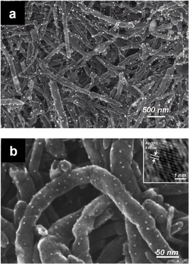
Ag nanoparticles decorated on MWCNTs (1 mol.% Ag) resulting from (a) 10 min ball milling and subsequent thermal treatment or (b) simple mechanochemical processing. Adapted with permission from ref. [79, 80]. Copyright 2009 American Chemical Society.
Kondrat et al. applied a similar approach, aiming at the preparation of chloride‐free Au and Au‐Pd nanoparticles supported on TiO2. [84] Since almost all the preparation methods of Au‐based catalysts use HAuCl4 as the gold precursor, the final catalyst inevitably contains some chloride residues, which are detrimental to the catalytic performance. For instance, the presence of chlorides was shown to cause particle agglomeration or the blocking of active sites. [85] To circumvent this, metal acetates proved to be more appropriate alternative precursors for metal nanoparticles, particularly considering their inclination towards auto‐reduction under an inert atmosphere and their potential to sublime. Herein, a thermal treatment had to follow manual grinding due to limitations related to the choice of the carrier, as previously underlined. Thus, in this case, the mechanochemical step only served to increase the dispersion of the metal precursor over the supporting material. However, in some other cases the low energy input exerted by manual grinding did not assure a sufficient degree of mixing of the two metal precursors before the thermal treatment. Consequently, the formation of Au‐Pd alloyed nanoparticles, which is greatly appealing, did not occur to an extent sufficient to be confirmed by XRD studies but was postulated according to the catalytic behaviour of the resulting material. Anyhow, it is not yet excluded that a more clear‐cut result might be achieved by using higher mechanical energy input.
Recently, studies on the mechanochemical synthesis of supported catalysts explored the use of coarse metal powders as precursors for the synthesis of the corresponding metal nanoparticles, which is very attractive due to the simplicity of handling metal powders as compared to metal salts.[ 37 , 86 ] Danielis et al., for instance, accomplished the preparation of a very active catalytic material by only ball milling palladium and ceria powders together. [86] The metal and support powders were placed in a 15 cm3 zirconia jar with a single grinding ball made of the same material (15 mm Ø, BPR=10) and then shortly processed in a mixer‐type mill under relatively mild conditions (the nominal frequency was 15 Hz). Only 10 min of milling was sufficient to obtain an excellent catalytic material for methane oxidation. Overall, the mechanically mixed sample (PdCeM) showed much higher activity than the reference catalysts with the same nominal Pd loading synthesized by incipient wetness impregnation (PdCeIW) or solution combustion synthesis (PdCeSCS) (Figure 10). The catalyst prepared by milling was also more stable than PdCeIW, both in a dry and wet atmosphere. Intriguingly, PdCeM was used as‐synthesized, and no further treatment preceded the catalytic test. According to the authors, the peculiar arrangement of Pd and ceria, which apparently develops upon ball milling, accounts for the observed catalytic behaviour. TPO and HR‐TEM studies further indicated that the mechanochemical treatment was responsible for the appearance of multiple palladium species. First, the formation of a compact and well‐defined amorphous layer surrounding the ceria crystallites was noted (Figure 11 a). Moreover, the existence of small mixed Pd‐Ce domains was highlighted by EDX analysis (Figure 11 b). Finally, nanosized Pd particles were also detected, still embedded in this amorphous shell (Figure 11 c, d). In general, such a configuration is unusual for supported catalysts prepared by conventional routes, as the formation of nanoparticles located on the surface of the metal oxide is more often observed. The reasons for the results found for PdCeM are not easily elucidated, and thus this is the aim of ongoing studies.[ 87 , 88 ] Nevertheless, it was speculated that the mechanochemical action might enhance the interaction between Pd and CeO2 and, thus, promote phase reconstruction. Ball milling of pure CeO2 does not bring about a similar change of the outer surface layers. The amorphization, therefore, seems to be dependent on the presence of Pd. Also, mixing PdO with CeO2 (PdOCeM) or Pd with an alternative metal oxide as ZrO2 (PdZrM) produces a material where well‐defined PdO and Pd nanoparticles are, respectively, found over the support. The formation of a specific nanoscale arrangement seems to be exclusively possible by ball milling, highlighting the potential of the mechanochemical approach as a means of nanostructuring.
Figure 10.

Light‐off curves for Pd‐CeO2 catalysts (2nd cycle). Solid line, closed symbols: heating part of the cycle; dashed line, open symbols: cooling part of the cycle. Conditions: GHSV ca. 200.000 h−1; 0.5 % CH4, 2 % O2, He to balance. Adapted with permission ref. [86]. Copyright 2018 Wiley‐VCH.
Figure 11.
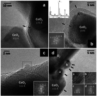
HRTEM images highlight the main features of PdCeM. (a,b) The ceria crystallites are covered by an amorphous layer (2–5 nm thick), delimited by black arrows. Top, left inset in b: EDX spectrum of the amorphous layer; bottom‐left inset in (b): lattice fringes of the ceria crystallites. (c, d) Representative palladium nanoparticles, decorating the ceria crystallites, with corresponding lattice fringes shown as an inset. Adapted with permission from ref. [86]. Copyright 2018 Wiley‐VCH.
This became clearer when a more general protocol to synthesize supported metal catalysts from bulk metal powders was reported. [37] This study originated in the occasional formation of supported metal nanoparticles during experiments on milling during the catalytic reaction itself.[ 35 , 36 ] As a result, Au was successfully dispersed as NPs over various exemplary supports, namely TiO2, Al2O3, Fe2O3, and Co3O4 (Figure 12 a–e). More interestingly, this strategy proved effective even when extended to other catalytically relevant metals, such as Pt, Ag, Cu, and Ni, revealing that such an approach could have a general application. All the experiments were performed in a shaker mill, with a milling capsule suitably modified to allow operation under continuous gas‐flow conditions. Notably, some of the materials were active catalysts under CO oxidation conditions already during ball milling. Full conversion was considered an early sign for the formation of metal nanoparticles, as later proven by XRD and EM studies. The samples were collected by interrupting the process at different milling times and characterized by the methods mentioned before. Accordingly, it was found that the comminution process reaches a steady‐state in approximately three hours, irrespective of the choice of the metal component. A moderately broad distribution of particles was formed, mostly in the sub‐10 nanometer range and with an average particle size typically lower than 5 nm. These samples were also studied in a conventional plug‐flow reactor to investigate their catalytic activity under better‐defined conditions. The activities of gold catalysts, in all cases, were not the highest ones reported for the given system in the literature but were comparable or even higher than those reported in many studies using conventionally synthesized catalysts. For instance, Au/TiO2 catalysts prepared by the mechanochemical route proved to be less active than those synthesized by deposition‐precipitation but showed higher activity than most of the systems synthesized via conventional impregnation methods. On the other hand, Ag, Ni, and Cu are not known as active CO oxidation catalysts, and thus their activity was expectedly relatively low. The Pt/TiO2 sample had activity in the same range as those reported in the literature for materials synthesized more traditionally.
Figure 12.
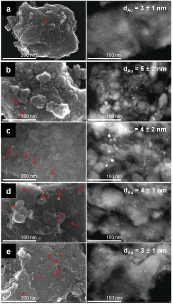
From top to bottom, electron micrographs of gold nanoparticles on (a) α‐Fe2O3, (b) Co3O4, (c) α‐Al2O3, (d) nano‐TiO2, and (e) TiO2 HombiKat. All the materials were obtained after 3 h of ball milling under a continuous flow of the following gas mixture: 1 % CO, 20 % O2, 79 % He. On the left, SEM images of the mentioned samples (red arrows point at the gold nanoparticles) and, on the right, STEM images of the corresponding microtomic cuts (average Au particle diameters, with standard deviations, are reported on the micrographs). Adapted with permission from ref. [37]. Copyright 2019 Wiley‐VCH.
Based on these results, the possibility of creating more complex catalyst formulations was explored: combining different coarse metal powders and subjecting them to mechanochemical processing in the presence of an oxide support leads to supported, alloyed nanoparticles, which further extends the field of application of the mechanochemical catalyst synthesis. [89] In particular, when Au and Pd, or Au and Cu, were mixed with MgO and ball milled in a high energy regime (i.e., in a shaker mill at 25 Hz), Au‐Pd and Au‐Cu bimetallic nanoparticles were obtained, supported on MgO, as evidenced via powder XRD and EM to confirm alloying. The synthesis was also successful when an yttria‐stabilized zirconia phase was employed as an alternative carrier. All mechanochemically synthesized materials were similarly active in CO oxidation as the corresponding conventionally prepared counterparts. Thus, ball milling could become a simple and low‐cost alternative to the solution processes applied ordinarily, which can be difficult to scale‐up, especially when bi‐ or polymetallic formulations are involved.
Reducing the amount of expensive noble metal components without severely compromising the catalyst performance is critically important due to the low natural abundance of noble metals and their high cost. Single‐atom catalysts (SACs) enable this by maximizing metal atom efficiency. A mechanochemical route was also recently shown to be suitable when aiming at the synthesis of noble metal SACs. [90] In this study, two types of acetylacetonate salts, Pd(acac)2 and Zn(acac)2, were selected as precursors of the noble metal active sites (Pd) and the support (ZnO). Notably, no additives, process control agents, solvents, or templates were employed. The physical mixture of Pd(acac)2 (0.25 wt.%) and Zn(acac)2 was placed in a 100 cm3 agate grinding jar with several grinding balls and milled at 400 rpm (planetary mill) for 0.25, 2, or 10 h. Processed powders were then recovered and calcined at 400 °C for 2 h in air. The unmilled mixture of the metal precursors was similarly subjected to calcination and the resulting material characterized. TEM analysis indicated the formation of Pd nanoparticles when the sample was not milled (Figure 13 a). In contrast, after ball milling, the number of Pd nanoparticles appearing on ZnO decreased with milling time. Only a few could be detected, for instance, on Pd/ZnO (0.25 h) (Figure 13 b). Moreover, when the milling period was extended (2 h), the degree of Pd dispersion increased further so that both individual Pd atoms and small Pd clusters were found (Figure 13 c). Finally, after 10 h of ball milling, only isolated Pd atoms could be identified (Figure 13 d). The mechanochemical treatment contributed to increasing the separation between the Pd(acac)2 molecules to an extent sufficient to prevent the aggregation of the Pd species during the subsequent calcination step. The use of a common ligand most likely favoured the diffusion of Pd(acac)2 into the bulk Zn(acac)2 upon milling. Extended X‐ray absorption fine structure spectroscopy (EXAFS) was additionally applied to investigate the degree of dispersion of Pd on ZnO. As illustrated in Figure 13 e, Pd‐O and Pd‐O‐Zn coordination environments emerged and became dominant with increasing milling time. This occurred at the expense of the Pd‐Pd contributions, which, on the other hand, faded away. Accordingly, the coordination numbers corresponding to the Pd‐Pd shell approached zero after extended milling (10 h) (Figure 13 f). All characterization results supported the dominance of atomically dispersed Pd species, homogeneously distributed on the ZnO support. Interestingly, the catalyst structure was retained, regardless of the synthetic scale, which was stepwise elevated from 10 to 60, 200, and 1000 g. Moreover, the catalytic performance demonstrated in typical reactions (e.g., phenylacetylene semi‐hydrogenation and CO oxidation) was broadly identical, again irrespective of the fabrication scale, including catalytic activity and stability, which is of significant importance for practical applications. The method also proved to have general applicability, as it was exploited for the synthesis of other representative single‐atom catalysts up to the kilogram scale, namely Ru/ZnO, Rh/ZnO, Ir/CeO2, Pd/CuO, Au/NiO, Au/ZnO, and Au/CeO2.[ 90 , 91 ] Overall, the approach demonstrated to be advantageous as a means to simplify the manufacture of SACs, which is typically hindered by complicated scale‐up procedures and high fabrication costs.
Figure 13.
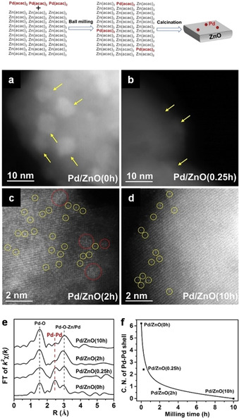
Top: schematic illustration of the fabrication process for Pd/ZnO. Middle: AC HAADF‐STEM images of (a) Pd/ZnO(0 h), (b) Pd/ZnO(0.25 h), (c) Pd/ZnO(2 h), (d) and Pd/ZnO(10 h). Yellow arrows highlight Pd nanoparticles, red circles highlight 2‐dimensional Pd rafts, and yellow circles highlight individual Pd atoms. Bottom: (e) The FT of k2‐weighted EXAFS spectra and (f) the coordination numbers (CNs) of the Pd‐Pd shell of Pd/ZnO(0 h), Pd/ZnO(0.25 h), Pd/ZnO(2 h), and Pd/ZnO(10 h). Adapted with permission from ref. [90]. Copyright 2019 The Authors.
4.2. Supported metal oxide nanoparticles
Metal oxides represent another common form of active phases deposited on a supporting material, which is similarly accessible by mechanochemical synthesis. A recent example of this is the mechanochemical preparation of highly active alumina‐supported Ag‐based catalysts for the low temperature (<200 °C) selective catalytic reduction (HC‐SCR) of nitrogen oxides (NOx) with hydrocarbons. [92] Ag‐based catalysts are one of the most promising and cost‐effective systems for HC‐SCR of NOx, showing good performance and moderate tolerance to water vapor and SO2, but their lack of activity below 350 °C remains a problem. A range of preparation methods (solution‐based) have been used, and their influence on the catalyst activity was complex. However, ball milling recently proved to be highly advantageous. Kamolphop et al. prepared supported Ag‐based catalysts via a two‐step method, involving the ball milling of Ag2O, AgNO3, or Ag powders, as precursors for Ag, in the presence of a γ‐Al2O3 support, followed by calcination. [92] In particular, Ag precursor and γ‐Al2O3 powders were first well‐mixed manually, and the resulting physical mixture was subjected to ball milling in a planetary mill using sintered corundum grinding jars (500 cm3) and balls (8 mm Ø) at a rotation speed of 150 rpm for 1 h. Mechanochemically processed powders were recovered and subsequently calcined at 650 °C for 2 h. For comparison, reference catalysts were also prepared by conventional routes (i.e., wet impregnation). In contrast to the catalyst prepared by wet impregnation (AgSTD), ball milling derived systems showed significantly improved performance as seen from their lower T 50 % (temperature to achieve 50 % NOx conversion) (Figure 14 c). Ball milling of the alumina support before wet impregnation (Ag/BM Al2O3) already resulted in a decrease in T 50 % to about 375 °C, even though the maximum NOx conversion was limited to 68 %. A similar decrease was observed upon the ball milling of the AgSTD catalyst itself (AgSTD_BM). More importantly, both the catalysts prepared by ball milling of AgNO3 or Ag with γ‐Al2O3 (AgNO3_BM and Ag_BM, respectively) showed similar activity with a T 50 % around 295 °C (and 90 % as the maximum value for the NOx conversion) (Figure 14 d). However, the most active catalyst was obtained by ball milling Ag2O with γ‐Al2O3 (Ag2O_BM), which showed a T 50 % as low as 240 °C (Figure 14 d). Almost full conversion (99 %) was achieved in the 300–400 °C range, and the onset of conversion of NOx was observed below 200 °C. The ball‐milled catalysts succeeded in activating n‐octane at sufficiently low temperatures so that the total concurrent combustion of n‐octane was prevented, and a good SCR of NOx observed. In these systems, the ball milling did not significantly increase the surface area of the catalyst. TEM studies of the impregnated and ball‐milled catalysts revealed similar size distributions of the Ag NPs in both mechanochemically (Figure 14 a, b) and conventionally‐prepared catalysts. Nevertheless, NMR correlation experiments and water TPD measurements coupled with in situ DRIFTS analysis indicated that the active sites on the ball‐milled Ag‐based catalysts more pronouncedly favour the formation of key intermediate species (NCO) by increasing the hydrophobicity of both the support and catalyst. As a result, these catalysts provide the right balance between sufficient amounts of water on the catalyst to hydrolyse the NCO species while not yet blocking sites for NOx or the hydrocarbon adsorption.[ 93 , 94 ] This concentration change, coupled with the lower energy barrier for n‐octane activation, could be the cause of the increased activity of ball‐milled catalysts as compared with the wet impregnated materials.
Figure 14.
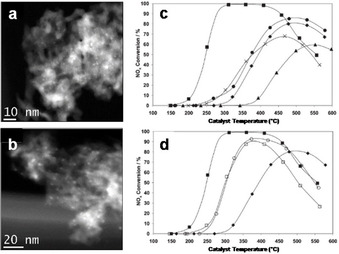
TEM images of (a) Ag_BM and (b) Ag2O_BM after calcination at 650 °C. (c, d) NOx conversion as a function of the catalyst bed temperature in the SCR of NOx with n‐octane over Ag catalysts. Feed stream: 720 ppm NO, 4340 ppm (as C1) n‐C8H18, 4.3 % O2, 7.2 % CO2, 7.2 % H2O, and He to balance. Space velocity: 60.000 cm3 g−1 h−1. ▪, Ag2O_BM; ⧫, AgSTD; •, AgSTD_BM; ×, Ag/BM‐Al2O3; ▴, AgSTD_BM; □, Ag_BM; ○, AgNO3_BM. Adapted with permission from ref. [92]. Copyright 2011 American Chemical Society.
Even though the performance of mechanochemically‐synthesized catalytic materials might not be outstanding, the mechanochemical approach at least proves itself as a convenient alternative to traditional methods, which can also be seen from the work of Firsova and co‐workers. [95] In their study, a highly active CuO/CeO2 catalyst in CO preferential oxidation (CO‐PROX) was simply obtained by the mechanochemical mixing (ball milling) of CuO and CeO2. Ball milling was performed under air in a high‐energy vibratory mill employing numerous small stainless‐steel balls for 30 to 120 min. Thus, catalysts with a nominal content of CuO in CeO2 of around 5 and 10 % were obtained. A reference 5 % CuO/CeO2 sample was obtained by supporting the copper oxide on CeO2 via impregnation of a copper nitrate solution, followed by drying at 150 °C and calcination at 500 °C for 2 h. All the materials were tested in CO oxidation in the presence of a large excess of H2, and their activity compared (Figure 15). Over CeO2, initial conversion of CO was observed only around 200 °C and reached a maximum of about 30 % above 350 °C (Figure 15, curve 1). The catalytic performance of CeO2 did not improve after the mechanochemical activation of the material. On the other hand, when the physical mixture of CuO and CeO2 was subjected to manual grinding in a mortar, a certain degree of activation was already achieved, as the maximum conversion of CO increased (Figure 15, curves 2 and 3). In turn, the catalytic activity increased sharply upon mechanochemical activation (ball milling), with a clear dependence on the milling time (Figure 15, curve 6–9). As recognized by the authors, the intrinsic catalytic activity would very likely increase further with milling time. However, this is overcompensated by a severe loss in surface area with extended ball milling (from 90 m2 g−1 of the 10 % CuO+CeO2 physical mixture to 20 m2 g−1 after 120 min of ball milling). Thus, a maximum CO conversion at the lowest possible temperature was observed after 90 min of mechanochemical activation (Figure 15, curve 8). Notably, the catalytic behaviour of 5 % and 10 % CuO/CeO2 resulting from 60 and 90 min of mechanochemical activation, respectively, was close to that of the reference catalyst prepared via wet impregnation (Figure 15, curve 10). The selectivity for oxygen consumption was almost the same for all of the samples. Interestingly, the structural characterization of the mechanochemically and conventionally‐prepared materials indicated that similar features appear, regardless of the preparation method applied. The phase composition and, eventually, the crystallite sizes of CuO and CeO2 were similar. Also, the formation of CuO‐CeO2 intermixed zones, which are assumed to be primarily responsible for the catalytic activity of the material, was observed both for the samples synthesized by wet chemistry or dry ball milling, so that the reduction of ball‐milled materials occurred in the same manner as compared to the reference sample. However, the mechanochemical route still proved to be the more practical and environmentally more benign synthetic technology.
Figure 15.
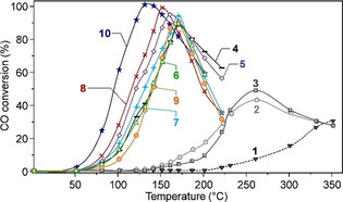
Conversion of CO over CeO2 (curve 1); over a physical mixture of 5 wt.% or 10 wt.% CuO and CeO2 (2 and 3, respectively); over 5 wt.% CuO on CeO2 after ball milling for 30 or 60 min (4 and 5, respectively); over 10 wt.% CuO on CeO2 after 30, 60, 90, or 120 min (from 6 to 9, respectively); over 5 wt.% CuO on CeO2 obtained via wet impregnation (curve 10). Adapted with permission from ref. [95]. Copyright Pleiades Publishing, Ltd., 2014.
Another example for the preparation of supported catalysts in a solvent‐free manner is given by Meng et al. [96] In this study, a simple mechanochemically‐assisted method was applied to prepare hydrotalcite supported Cu‐Mn mixed oxide under solvent‐free conditions. [96] The synthetic procedure consists of three consecutive steps: (i) the physical mixture of Cu(NO3)2 ⋅3 H2O, Mn(NO3)2 ⋅4 H2O, and hydrotalcite is manually finely grounded using an agate mortar and pestle (for at least 10 min); (ii) the solid mixture thus obtained is then transferred into a 100 cm3 agate jar (planetary mill fit) and ball‐milled at a rotation speed of about 150 rpm for 2 h using a combination of differently sized agate grinding balls; (iii) the resulting powders are dried at 80 °C for 5 h and subsequently calcined at 350 °C for 2 h. A series of reference samples was obtained by impregnating hydrotalcite with an alcoholic solution (EtOH) of the Cu and Mn nitrates followed by drying (80 °C, 5 h) and calcination (350 °C, 2 h). The catalytic performance of the as‐synthesized materials was investigated in the oxidative synthesis of 2‐acylbenzothiazole from α‐hydroxyacetophenone and 2‐aminothiophenol in EtOH using O2 as oxidant.
Interestingly, it was noted that the catalysts prepared by wet‐impregnation or by simple grinding (not followed by mechanochemical mixing) provided lower yields as compared to those synthesized via ball‐milling (69 % and 44 % vs. 86 %, respectively). By taking into account the formation of Cu‐Mn mixed oxide species as a measure of the degree of mixing achieved, the authors concluded that manual grinding using a mortar and pestle is inferior to ball milling. In the former case, the formation of CuMn2O4 indeed was not observed. Similarly, the wet‐impregnation method was not able to generate Cu‐Mn mixed oxide species. Further characterization via SEM (Figure 16) and TEM suggested that the ball‐milled samples showed the highest degree of dispersion of the metal oxides over the surface of layered hydrotalcite. However, the different catalytic behaviour was mostly attributed to the largest concentration of reactive surface oxygen species found (by XPS) over the ball‐milled samples compared to the other materials. The substrate scope of the catalyst was successfully extended to various substituted 2‐acylbenzothiazoles. Remarkably, in some cases, a gram‐scale synthesis was also viable. Heterocyclic compounds are indeed versatile building blocks and valuable structural motifs in pharmaceuticals owing to their broad biological activities. Many synthetic methods have been developed for obtaining functional benzothiazoles. However, for the synthesis of 2‐acylbenzothiazoles, only a few approaches have been established so far. As a result of the study, an efficient solid catalyst for the clean and potentially scalable synthesis of heterocycles under environmentally benign conditions was obtained. This could prove to be a valuable alternative to the costly homogeneous methods that are applied by default.
Figure 16.
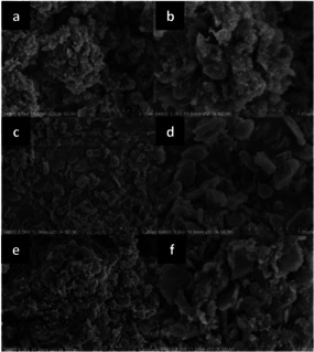
From top to bottom, SEM images of Cu‐Mn mixed oxide NPs supported on HT prepared by (a,b) manual grinding, (c, d) wet impregnation, or (e, f) mechanochemical mixing of the support with the metal precursors, followed by calcination. On the left, images collected with lower magnification (scale, 2 μm), on the right, with higher magnification (scale, 1 μm). Adapted with permission from ref. [96]. Copyright of The Royal Society of Chemistry 2018.
In the same direction, Pineda and co‐workers developed an innovative ball milling method, among others, for the stabilization of metal oxide nanoparticles on porous supports.[ 97 , 98 , 99 ] In particular, they studied the deposition of iron and cobalt oxide nanoparticles on Al‐SBA‐15, due to their excellent catalytic properties in a wide range of reactions, including some concerned with environmental remediation.[ 97 , 98 ] In a typical synthesis, the mesoporous aluminosilicate support (Al‐SBA‐15) is ball‐milled with an appropriate amount of the metal precursor (FeCl2 ⋅4 H2O or CoCl2 ⋅6 H2O) in a planetary mill using a stainless steel jar (125 cm3) and balls (10 mm Ø). Various parameters were investigated, but the milling frequency and times were noted as critical. Mild mechanochemical conditions (350 rpm) and relatively short reaction times (10 min) were eventually preferred as a compromise to achieve a sufficient dispersion of the metal precursors while preventing any severe damage to the delicate structure of the supporting material during the process. The materials thus obtained were then calcined at 400 °C for 4 h. As clearly shown by the TEM images (Figure 17 c, d), the textural properties of the mesoporous support are retained. Also, BET surface areas do not differ notably from those of the starting materials, along with pore sizes and volumes, provided that limited metal loadings are applied. The formation of highly dispersed and homogeneously distributed metal oxide NPs, particularly on the external surface of the support, is similarly evident (Figure 17 c, d). Besides, the XRD patterns show distinctive reflections for Fe2O3 and Co3O4 for the corresponding system, but only when higher metal loadings are used, which is consistent with their respective small particle size (Figure 17 a, b). Interestingly, the size of the metal oxide nanoparticles deposited via the mechanochemically‐assisted procedure was remarkably smaller (<5 nm) than that obtained by conventional or microwave‐assisted impregnation (5–10 nm) after calcination under similar conditions and at a nominal metal loading of 0.5 % in weight. A plausible mechanism for the formation of supported metal oxide nanoparticles involves, at first, the mechanochemical activation of the surface silanol groups on the aluminosilicate support, which may promote the hydrolysis of the metal precursors to the corresponding hydroxides. Upon calcination, the metal hydroxide intermediates could turn into their oxide counterparts in the form of nanoparticles. The proposed mechanism was especially demonstrated for the deposition of iron oxide nanoparticles on Al‐SBA‐15. [97] The supported metal oxide catalysts were tested in the oxidation of benzyl alcohol to investigate related redox properties, whereas the alkylation of toluene with benzyl chloride served as a test reaction to study the acid properties of the catalytic materials. Overall, the as‐synthesized materials proved to be very active, and in some cases, the catalytic performance even surpassed that of conventionally‐prepared analogues. The preparation of a niobium oxide catalyst supported on Al‐SBA‐15 was achieved in a similar manner. [99]
Figure 17.
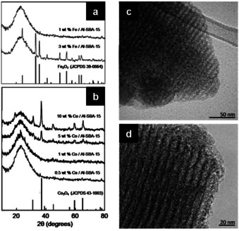
Powder XRD patterns of (a) Fe/Al‐SBA‐15 and (b) Co/Al‐SBA‐15 for different metal loading of Fe and Co, respectively. TEM images of (c) 1 wt.% Fe/Al‐SBA‐15 and (d) 0.5 wt.% Co/Al‐SBA‐15. Adapted with permission from ref. [97], Copyright 2011 Wiley‐VCH; and from ref. [98], Copyright 2018 by Elsevier Inc.
5. Mixed Oxides and Nanocomposite Catalysts
Mixed oxides and nanocomposites, such as multinary oxides, solid solutions, or doped systems, are another important class of catalytic materials. They can provide distinct advantages in terms of synergistic effects (originated from the interactions of components present in the system), which, in several instances, are considered as responsible for the observed improved conversion, selectivity towards the desired product, and catalyst lifetime. [100] Mechanochemical synthesis has also been shown as a suitable synthetic route for the preparation of mixed oxides and nanocomposites containing various metal ions. Some representative cases are discussed in the following subsections.
5.1. Spinel oxides
The spinel family of oxide materials (AB2O4, wherein the prototypical form A=divalent cation, B=trivalent cation) has demonstrated interesting magnetic, optical, electrical, and catalytic properties as the result of the availability of numerous compositions, electron configurations, and valence states. [101] From a catalysis viewpoint, the possibilities of controlling composition, structure, valence, and morphology have made spinel systems suitable as catalysts in many different reactions, including NOx reduction,[ 102 , 103 ] CO oxidation, [104] CO2 reduction, [105] hydrogen evolution reaction (HER), [106] oxygen reduction reaction (ORR), [107] oxygen evolution reaction (OER), [108] and alcohol oxidation.[ 109 , 110 ] Spinel oxides based on Mg‐Al, Fe‐Co, Mg‐Fe, Ni‐Fe, Zn‐Fe, and Zn‐Al systems are the most important ones among the ternary oxides—together with the perovskite family—and can be fabricated by ball milling.[ 111 , 112 , 113 , 114 , 115 , 116 , 117 , 118 , 119 ] In general, the mechanochemical synthesis of spinel oxides is based on a bottom‐up approach, involving the ball milling of the oxide, oxyhydroxide, or hydroxide metal precursors at room temperature in air. The resulting solid mixture may then be subjected to further treatments, such as mild calcination.
One of the most common spinel structures is magnesium aluminate (MgAl2O4), which gave its name to the family. In its mechanochemical synthesis, transition alumina (γ‐Al2O3), boehmite (γ‐AlOOH), or corundum (α‐Al2O3) are ball milled together with MgO in stoichiometric ratio at room temperature under air. [112] Interestingly, the rate of formation of MgAl2O4, which was reported to depend on the type of aluminium compound used, decreased in the following order: γ‐Al2O3>γ‐AlOOH>α‐Al2O3. This difference is related to the structural similarity of the γ‐Al2O3 (defective spinel) precursor and the product MgAl2O4 (spinel). [112] About 99 % MgAl2O4 was reported to form after 140 h ball milling of γ‐Al2O3‐MgO mixture.
The combination of cobalt and iron offers interesting spinel structures, as they both are redox‐active. The availability of multiple oxidation states (and hence redox properties) results in two types of spinel, namely, CoFe2O4 and FeCo2O4. The synthesis of these materials has been shown by Manova et al. in a two‐step preparation method, combining co‐precipitation with subsequent high‐energy ball milling (Figure 18).[ 116 , 117 ] In the co‐precipitation step, the nitrate salts of Fe and Co were first mixed in the desired molar ratio, followed by the addition of a solution of sodium carbonate, which leads to the formation of mixed cobalt and iron hydroxide carbonates via precipitation. Finally, after drying, the precipitate powder was subjected to ball milling for 1–3 h (in a planetary mill using steel vial and balls). From XRD analysis, the precursors (i.e., cobalt and iron hydroxide carbonates) showed characteristics of layered double hydroxides (LDH) as found for [Mg6Fe2(OH)16CO3 ⋅4 H2O] (i.e., pyroaurite) and [(Mg6Al2(OH)16CO3 ⋅4 H2O] (i.e., hydrotalcite) (Figure 19 a, b). After 1 h of milling, the formation of spinels, CoFe2O4 and Co2FeO4, was evident, and after 3 h, the spinel reflections were well defined. The average crystallite size (D), determined from the XRD patterns, slightly increased with milling time. Still, after 3 h milling, the D values (8.6 nm and 3.8 nm for CoFe2O4 and Co2FeO4, respectively) were significantly smaller than for the thermally derived samples (18.9 nm and 10.5 nm for CoFe2O4 and Co2FeO4, respectively). Additionally, both the mechanochemically‐derived systems showed improved reducibility, with reduction peaks shifted to lower temperatures as compared to their thermally‐derived counterparts. [117] This is advantageous from the catalysis perspective. Spinel ferrites of other redox metals, such as Ni and Zn, have also been similarly synthesized via direct ball milling of hydroxide precursors.[ 114 , 119 ]
Figure 18.
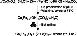
Mechanochemical synthesis of cobalt‐iron spinel oxide.[ 116 , 117 ]
Figure 19.
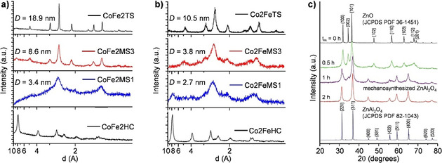
Powder XRD patterns of (a) CoFe2O4 and (b) Co2FeO4 precursors (hydroxide carbonates, HC) before and after different mechanochemical syntheses (MS) (i.e., ball milling) for different milling times (1 or 3 h) and thermal synthesis (TS). Adapted with permission from ref. [117], Copyright 2009 Elsevier B.V. (c) Powder XRD patterns of a mixture of ZnO and γ‐Al2O3 milled for different times (tm=0–2 h). For comparison, bulk ZnAl2O4 prepared by a conventional ceramic route is shown at the bottom. Adapted with permission from ref. [113], Copyright 2015 The Royal Society of Chemistry.
The synthesis of zinc aluminate (ZnAl2O4) is challenging via conventional routes as it usually requires relatively high temperatures, which can lead to the loss of zinc due to its high volatility. [113] To solve this problem, mechanochemical grinding proved advantageous, enabling the synthesis of zinc aluminate readily at room temperature. It is reported that ball milling an equimolar mixture of ZnO and γ‐Al2O3 in a planetary mill for 2 h results in high purity ZnAl2O4 NPs, with an average nanocrystallite size of 10 nm (Figure 19 c). [113] Therefore, mechanochemistry offers an attractive alternative route enabling the synthesis of various spinel structures under mild conditions.
5.2. Perovskites
Perovskites (ABO3) constitute another important class of ternary oxides. They have long been recognized as highly active redox catalysts with several relevant applications, especially in environmental catalysis, such as CO oxidation, de‐NOx, and catalytic combustion of volatile organic compounds (VOCs),[ 120 , 121 ] as well as electrode materials for solid oxide fuel cells (SOFCs). [122] Besides, perovskite oxides recently showed promising performance in (photo)electrocatalytic water splitting.[ 123 , 124 ] However, like other mixed oxides, a high‐temperature step is required for their formation via conventional synthetic methods (e.g., co‐precipitation of corresponding metal salts to obtain a mixed precipitate, followed by calcination to form the perovskite structure), which inevitably reduces the surface area and limits their applications. Again, the mechanochemical route has been shown to be highly effective in obtaining perovskite‐type oxides with improved textural properties.
The synthesis of rare‐earth perovskites (e.g., LaCoO3) by mechanochemistry is widely studied. These systems generally require a calcination step at 800 °C for their formation and thus have low surface areas. [125] Consequently, a mechanochemical route, simply enabling their formation at room temperature, could be particularly beneficial. Kaliaguine et al. have extensively studied the mechanochemical synthesis and catalytic applications of LaCoO3‐based perovskites.[ 126 , 127 , 128 , 129 , 130 , 131 , 132 , 133 ] The mechanochemical synthesis of LaCoO3 involves the ball milling of the oxide components in a shaker mill, namely La2O3 and Co3O4 (La:Co molar ratio of 1). [126] The process was performed at room temperature in air or a pure oxygen atmosphere for 1–20 h. The formation of LaCoO3 was reported to occur in both tempered steel and tungsten carbide milling vessels and media.
Figure 20 shows the XRD patterns displaying the evolution of the LaCoO3 crystalline phase from the La2O3 and Co3O4 oxide mixture. The formation of the perovskite phase started after about 4 h of milling, and complete conversion of the oxide components was observed after 16 h of milling in air. The formation of LaCoO3 occurred much faster when the milling was instead performed in a pure oxygen atmosphere. [126] The surface area of LaCoO3 resulting from 20 h of ball milling in air was 16 m2 g−1. A higher surface area (36 m2 g−1) was achieved when the milling was performed in humidified air. Ball milling of the oxide components in the presence of easily leachable additives, such as NaCl, NH4Cl, or ZnO, allowed the production of LaCoO3 with a surface area up to 105 m2 g−1, which is quite impressive from a catalysis standpoint. [126]
Figure 20.
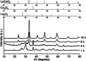
Powder XRD patterns of a La2O3 and Co3O4 mixture after ball milling in air using a tempered steel grinding jar for different times (1–16 h) in the absence of any grinding additive. Reference lines for various phases are shown at the top of experimental diffractograms. The formation of LaCoO3 perovskite occurs after about 4 h milling, and complete conversion of oxide components occurs after 16 h of milling. Adapted with permission from ref. [126], Copyright 2001 Elsevier Science B.V.
In addition to the increase in surface area, the surface chemical properties of the mechanochemically‐derived LaCoO3 perovskites were of particular interest. Given that the grinding process was performed at low temperature (room temperature), the perovskite surface exhibited a high concentration of surface hydroxyls, which upon calcination, led to the reformation of the material framework. [126] Accordingly, the cobalt species in the perovskite thus obtained are shown to be highly reducible, which might be beneficial in redox catalysis. Overall, these modified surface properties could bring about extraordinary catalytic properties as compared to conventionally prepared counterparts.
When ball milling was performed using stainless steel milling vessel and balls, some iron contamination was reported due to abrasion. Serendipitously, this led to the formation of an exotic mixed perovskite (LaCo1−xFex+ϵO3−δ), highlighting the great potential of mechanochemical processing for the preparation of complex systems.[ 126 , 127 , 128 ] In fact, other mixed LaMO3 (M=Co, Mn, Fe, Mg, or Ti) perovskites—such as LaCo1−xCuxO3, LaCo1−xPdxO3, LaMn1−xCuxO3, LaFe1−xCuxO3, LaTi0.5Mg0.5O3, and LaTi0.4MgyFexO3—were produced by ball milling.[ 129 , 130 , 131 , 132 , 133 , 134 , 135 , 136 ] Interestingly, the synthesis of ABO3 perovskites, with A=Ca, Bi, or Ba and B=Mn, Ti, Zr, or Fe, was also achieved mechanochemically.[ 137 , 138 , 139 ] These perovskite systems show improved catalytic performance compared to reference samples in many reactions, such as VOCs oxidation, CH4 oxidation, CO oxidation, NO reduction, toluene oxidation, and biodiesel synthesis (by the methanolysis of sunflower oil).[ 127 , 128 , 129 , 130 , 131 , 132 , 133 , 134 , 135 , 136 , 137 ] In most cases, the enhanced performance was related to the increased surface area and/or high defect density resulting from reactive grinding. Moreover, recently halide perovskites, such as methylammonium lead iodide and caesium lead iodide, which already have demonstrated impressive photo‐conversion efficiency, were also successfully synthesized by ball milling.[ 140 , 141 ]
5.3. Mixed metal oxide nanocomposites, doped oxides, and solid solutions
Mixed metal oxide nanocomposites, obtained from two or more metal oxides, exhibit interesting synergistic effects that can help achieve improved catalytic performance in photochemical and thermochemical reactions.[ 100 , 142 , 143 ] Different metal oxide nanocomposites, such as CeO2‐MnOx, CuO‐ZnO, SnO2‐ZnO, have been fabricated relying on various methods, solution‐based mostly.[ 142 , 143 ] The mechanochemical route offers a solvent‐free alternative for these systems and has been described for the preparation of SnO2‐ZnO, [144] Fe2O3‐TiO2,[ 145 , 146 ] CuxO‐TiO2, [147] MoO2‐Fe2O3,[ 148 , 149 ] CuO‐CeO2.[ 150 , 151 ]
The synthesis of SnO2‐ZnO photocatalysts involves the mechanochemical treatment of anhydrous chloride precursors (SnCl2 and ZnCl2) with Na2CO3 in the presence of NaCl. [144] Subsequent thermal treatment of the reactant mixture enables the formation of a composite powder composed of metal oxide grains embedded in a NaCl matrix (Figure 21 a). The latter matrix is then removed by repeated washings with distilled water, an operation that eventually will lead to the undesired partial hydration of the oxide product into ZnSn(OH)6. The dehydration of the latter was studied at different temperatures (400–700 °C) (Figure 21 b). The SnO2‐ZnO composite obtained by ball milling, followed by washing and thermal treatment at 700 °C, exhibited higher photocatalytic activity than either SnO2 or ZnO individually. [144] The improved activity was attributed to the higher specific surface area and the enhanced charge separation from the proximity of ZnO and SnO2.
Figure 21.
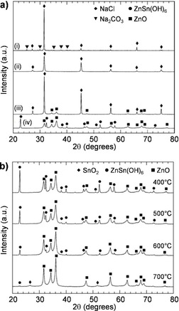
(a) Powder XRD patterns of 0.1 SnCl2+0.9 ZnCl2+Na2CO3+4 NaCl after (i) mixing in a mortar and pestle, (ii) ball milling for 4 h, (iii) heat‐treatment at 400 °C for 1 h, and (iv) washing. (b) Powder XRD patterns of various (SnO2)0.1(ZnO)0.9 powders synthesized by heat‐treatment at 400, 500, 600, and 700 °C. Adapted with permission from ref. [144], Copyright 2006 IOP Publishing Ltd.
Direct mechanochemical synthesis of mixed metal oxide composites from the corresponding constituents was also reported, and it was highly efficient.[ 145 , 146 , 152 ] Ghorai et al. obtained Fe2O3‐TiO2 composites (Fe2O3 up to 10 mol %) combining anatase TiO2 with yellow Fe2O3, red Fe2O3, or precipitated Fe(OH)3. [145] XRD analysis of the ball‐milled mixture showed titania as the dominant phase (Figure 22 a). Since no reflection specific to iron compounds (e.g., iron oxide or metallic iron) was observed in XRD patterns, the authors of this study suggested that the Fe species might have been inserted into the framework of anatase TiO2. [145] The maximum solubility of Fe2O3 in TiO2 was reported to be as high as 5 mol %. Remarkably, the Fe2O3‐TiO2 composite containing 5 mol % of Fe2O3 exhibited 3–5 times higher photocatalytic activity than P25 TiO2.
Figure 22.
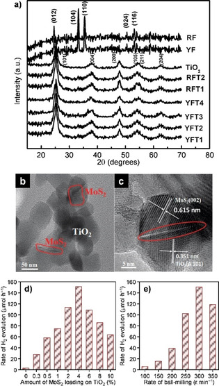
(a) Powder XRD patterns of TiO2 (T), red Fe2O3 (RF), yellow Fe2O3 (YF), 4 h ball milled mixtures of TiO2+red or yellow Fe2O3 (with RF or YF content of 5 mol.% (RFT1 or YFT1), 7 mol.% (RFT2 or YFT2), and 10 mol.% (YFT3)), and of YFT1 after photocatalytic degradation of dye (denoted as YFT4). Adapted with permission from ref. [145], Copyright 2011 Elsevier B.V. (b) TEM and (c) HRTEM images of the 4 % MoS2‐TiO2 photocatalyst, (d, e) the rate of H2 evolution on MoS2‐TiO2 with d) various MoS2 loadings, and (e) different ball milling speeds in a mixed methanol‐H2O solution. Adapted with permission from ref. [152], Copyright 2015 the PCCP Owner Societies.
MoS2 is known for its positive effect on enhancing the activity of photocatalysts.[ 153 , 154 , 155 ] However, the formation of its composite with photocatalysts, such as TiO2 or CdS, requires sophisticated reduction methods involving NH4MoS4 or Na2MoO4 as precursors.[ 152 , 153 , 154 , 155 ] In contrast, mechanochemistry offers a more straightforward synthetic route, consisting of mere ball milling of MoS2 and TiO2 in ethanol. [152] After ball milling, the ethanol can be readily removed by drying the material in air.
Multiple characterization methods (e.g., XRD, UV/Vis, and Raman spectroscopy) identified the presence of both MoS2 and TiO2 phases in the resulting solid mixture. Also, TEM and HRTEM studies indicated the formation of intimate contacts between MoS2 and TiO2 particles (Figure 22 b). The MoS2‐TiO2 composites displayed distinctly higher H2 evolution activity compared to TiO2 (Figure 22 c). The activity was shown to depend on the content of MoS2 and the intensity of ball milling (Figure 22 d). The improved catalytic performance in these systems, especially for 4 % MoS2‐TiO2, was attributed to an optimal interaction at the interface between MoS2 and TiO2, attained by mechanochemical activation at 300 rpm.
The photocatalytic performance of TiO2 could also be improved via nitrogen‐doping as it can narrow down the band gap and eventually enable the absorption of visible light. [156] In contrast to conventional sputtering (followed by calcination), N‐doped TiO2 can be readily attained by ball milling.[ 157 , 158 , 159 , 160 ] In its synthesis, TiO2 (most commonly P25) is ball milled with a nitrogen source compound. The nitrogen compounds reported thus far include hexamethylenetetramine, ammonium carbonate, aqueous ammonia solutions, and ammonium fluoride. The ball‐milled solid mixture is then calcined at 400 °C to remove any potentially unreacted nitrogen compound and organic by‐product. Eventually, milling will induce phase transformation of TiO2, as previously reported. For instance, P25 titania (i.e., 3:1 mixture of anatase and rutile) was observed to undergo the phase transition from anatase to brookite and finally rutile in a dedicated study of Yin and colleagues. [160] No distinct phase for N‐doped TiO2 could be detected by XRD analysis. It is reported that the doping changes the appearance of the TiO2 powder to yellowish.
Catalysed thermochemical reactions can also benefit from the synergistic interactions established in mixed metal oxide composite catalysts upon ball milling. The case of CeO2, which is widely used as a redox catalyst, owing to its intrinsic ability to easily store and release oxygen species during a catalytic event (also known as oxygen storage capacity, OSC), is of particular interest.[ 161 , 162 ] The OSC of ceria can indeed be altered by forming a composite with other oxides, such as ZrO2 and CuO.[ 151 , 163 ] CuO‐CeO2 composites, prepared by ball milling CuO and CeO2 together, showed higher reducibility than the individual components and exhibited much higher OSC values, which increased with the milling duration (Figure 23 a). [151] The ball milling derived CuO (10 wt.%)—CeO2 composite showed a significant drop in the light‐off temperature for the CO‐PROX reaction as compared to CeO2 or a CuO‐CeO2 physical mixture (Figure 23 b). [150] In addition to the OSC, it was also reported that ball milling could alter the chemical state of copper on CeO2, depending on the mechanical energy input.[ 150 , 151 ] Based on in‐depth bulk and surface structural characterization, Borchers et al. concluded that the catalyst surface consists of terminated CeO2 nanofragments, doped by Cu1+, Cu2+, and possibly Cu3+ ions.
Figure 23.
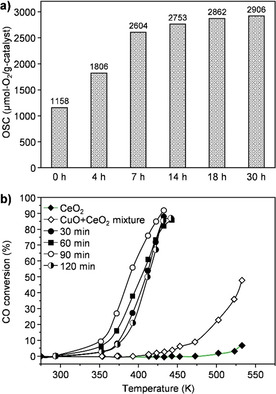
(a) Total oxygen storage capacity (OSC) at 300 °C of (CuO)0.5(CeO2)0.5 powder versus ball milling time. Adapted with permission from ref. [151], Copyright 2019 The Authors. (b) CO conversion to CO2 as a function of reaction temperature over CeO2 ball milled for 60 min and CuO‐CeO2 powders mixed in an agate mortar and ball milled for 30–120 min. Reaction conditions: 98 vol. % H2, 1 vol. % CO and 1 vol. % O2, a flow rate of 40 cm3 min−1, 20 mg of the catalyst. Adapted with permission from ref. [150], Copyright 2019 Author(s).
ZrO2 is one of the most common oxides used in combination with CeO2 (in a solid solution form) to improve the OSC of the latter. [162] A mechanochemical route has been explored for the synthesis of CeO2‐ZrO2 solid solutions.[ 164 , 165 , 166 ] Hydrated nitrate or carbonate precursors usually are used, most likely due to their low hardness, which is much lower than that of corresponding anhydrous salts and oxides, which reduces contamination due to possible abrasion of milling vessels and balls. To obtain the final CeO2‐ZrO2 composite, the ball‐milled mixture is subsequently subjected to a thermal treatment at or above 400 °C. The XRD and TGA analysis suggested that the reaction between ZrO(NO3)2 ⋅ n H2O and Ce(NO3)3 ⋅6 H2O occurs already during ball milling. [164] The authors postulated that the structures of the crystalline nitrates break down as a result of milling‐induced plastic deformations, which most likely involves the formation of defect‐rich regions (with high densities of vacancies, interstitial defects, and dislocations), where the reaction between the nitrates could be initiated during mechanical activation. Eventually, the post‐grinding activation temperature for the calcination is lowered by approximately 70 °C. Remarkably, the mechanochemically derived CeO2‐ZrO2 solid solutions exhibited lower light‐off temperatures (i.e., higher activity) compared to CeO2 or ZrO2 in the total oxidation of propane and naphthalene.[ 165 , 166 ] The rate of the total oxidation of propane and naphthalene was found to correlate with the relative surface concentration of Oβ (defective oxygen sites) determined by XPS analysis.
6. Hybrid Materials
Mechanochemical synthesis has also become an important alternative to several solution‐based methods applied for a great variety of complexation reactions. Mechanochemical methods have proven to be not only more straightforward, as compared to traditional synthetic strategies, but also more selective, giving high reaction yields. [14] Already the simple action of pestle and mortar is often sufficient to promote selective activation of some types of bonds while keeping other types intact, thus providing new synthetic pathways to compounds of interest, including supramolecular assemblies and coordination polymers. In this section, the advances achieved in the mechanochemical surface functionalization and the preparation of metal‐organic frameworks (MOFs) are discussed.
Hybrid materials prepared by combining inorganic and organic counterparts (HIOM) are an important class of functional materials as they combine characteristics of inorganic solids with those of the organic functional moieties. [167] Among their numerous applications, such as in optics, microelectronics, health, and housing, HIOMs are also important in catalysis. [168] The organic part (e.g., amine) can, for instance, act as an anchoring point for a homogenous complex, enabling its heterogenization. [169]
A recent study reported a highly efficient synthesis of such HIOMs by mechanochemistry (Figure 24). [78] It consists of ball milling of an inorganic solid with an organosilicon compound (e.g., silane) for 5 min in a shaker mill (WC vessel, 25 cm3, and 3 balls, 12 mm in diameter). The milling vessels were charged with solid, silane, and milling media in an open atmosphere, which makes this method particularly attractive compared to laborious conventional routes, often requiring the use of an inert atmosphere. For surface functionalization of SBA‐15 with octadecyltrimethoxysilane (OTMS), [78] ball milling of hydroxyl‐rich SBA‐15 with OTMS was performed for 5 to 60 min using 0.589–2.357 mmolOTMS gSBA‐15 −1 (i.e., 18—47 wt.% OTMS concerning the total weight of ball‐milled OTMS and SBA‐15) followed by washing of the sample with ethanol/water (for analysis purpose) to remove any of possibly physisorbed silane. The successful grafting of OTMS on SBA‐15 was confirmed by different characterization methods (Figure 25).
Figure 24.
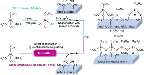
Schematic representation of hybrid inorganic‐organic material synthesis by chemical grafting via the conventional solvothermal route (top) versus solvent‐free mechanochemical synthesis (bottom) shown for the functionalization of solids with OTMS. Adapted with permission from ref. [78], Copyright 2020 American Chemical Society.
Figure 25.

Mechanochemical grafting of SBA‐15 with OTMS. (a) XRD patterns, (b) N2 sorption isotherms, (c) pore size distribution, (d) TGA weight loss profiles, (e) ATR‐FTIR spectra, and (f) 29Si MAS NMR spectra of SBA‐15 before and after ball milling with different amounts of OTMS for different times as shown in (b). Colour codes are given in (b) also apply to data in other figures (a–f). Adapted with permission from ref. [78], Copyright 2020 American Chemical Society.
TGA‐MS of the mechanochemically obtained SBA‐15‐OTMS composite showed a sharp loss between 400 and 800 °C due to the decomposition of the octadecyl group and unreacted methoxy groups of the anchored silane (as detected in MS) (Figure 25 d). It was also noted that the weight loss after 5 min or 60 min of milling was similar (Figure 25 d, red and purple curves), suggesting that 5 min of ball milling is sufficient to induce the direct condensation reaction between OTMS and surface hydroxyls. ATR‐FTIR analysis showed typical absorption bands at (i) 2926 and 2854 cm−1 for antisymmetric and symmetric stretching vibrations, respectively, and at 1465 cm−1 for bending vibration modes of CH2 groups, and (ii) at 1404 cm−1 for the bending vibration of the CH3 group (Figure 25 e). These results confirmed the presence of methylene and methyl groups on the functionalized samples. 29Si MAS NMR analysis evidenced that OTMS is chemically bonded to SBA‐15 (Figure 25 f). The spectrum of the as‐synthesized SBA‐15 showed three lines at about −92, −101, and −111 ppm, assigned to Q2, Q3, and Q4 sites, respectively. On the other hand, the spectrum collected after ball milling (47 wt.% of silane) showed a decrease in the relative intensities of Q2 and Q3 lines and the appearance of Tm lines at about −47, −57, and −67 ppm for T1, T2, and T3, respectively. These results indicated that the mechanochemical grafting of alkoxysilanes leads to chemical bonding. Furthermore, it is shown that the hexagonal ordering of SBA‐15 remained intact after functionalization with OTMS (Figure 25 a). Likewise, the type IV isotherm was retained upon functionalization (Figure 25 b). However, the pore width and pore volume were reduced (Figure 25 c), suggesting that the functionalized silane moieties occupy some of the pore volume.
The above method was extended to various silanes (with SBA‐15), such as (3‐aminopropyl)triethoxysilane, chlorodimethylethylsilane, and chlorodimethyl‐n‐propylsilane, and other inorganic solids (with OTMS), such as γ‐Al2O3, SiO2‐gel, and TiO2. In all cases, the formation of corresponding HIOM was confirmed by various characterization methods. Mechanochemical processing is thus a versatile, green, and simple approach for surface functionalization of solids. [78]
The research in the field of MOFs has become very intense over time due to the variety of potential uses and applications that are available for this class of materials. Briefly, MOFs result from the self‐assembly of metal‐containing units (otherwise named secondary building units, SBUs) and multitopic organic ligands, meant to act alternatively as nodes and linkers for the establishment of an open extended structure. The flexibility with which the metal SBUs and organic linkers can be varied has led to an extensive combinatorial library of compounds with unique features. [170] Available high surface areas, tuneable pore metrics, and high density of potentially active sites offer many advantages in catalysis (e.g., to support molecular catalysts, stabilize short‐lived catalysts, perform size selectivity, encapsulate catalysts within their pores). [171] Nevertheless, conventional solution‐based approaches to MOFs have some disadvantages in chemical manufacturing, as they rely on the combination of soluble metal salts (e.g., nitrates or chlorides) with organic ligands at high temperatures and in high‐boiling and often toxic solvents. On the other hand, mechanochemistry provides the opportunity to process efficiently poorly soluble feedstock (e.g., metal oxides or carbonates) in a nearly solvent‐free reaction environment at room temperature. [172]
The mechanochemical transformation of ZnO into a zeolitic imidazolate framework (ZIF) by contact with imidazole‐type ligands is possibly the most deeply investigated case study. At the very beginning, the dry mechanochemical synthesis of metal imidazolates from the corresponding metal oxides was rather laborious, leading mostly to a mixture of unreacted material and poorly crystalline products or no reaction at all, regardless of energy regime explored or reaction times. [173] However, Friščić and co‐workers soon discovered that the mechanochemical reactivity could be improved by the addition of sub‐stoichiometric amounts of salts (e.g., NH4NO3, NH4CH3SO3, and (NH4)2SO4), in the presence or absence of small amounts of a liquid (e.g., DMF, DEF, EtOH). The use of inorganic salts in combination with small amounts of a liquid as grinding solvent (an approach later referred to as ion‐ and liquid‐assisted grinding, ILAG, or just LAG in the absence of the salts) has great importance in the work of Friščić and co‐workers. [174] In fact, these modifications allowed the synthesis of several porous and nonporous ZIFs, with known and even unknown topology (Figure 26). [175] Interestingly, the choice of the process control agents affected the outcome of the mechanochemical transformation, with a significant impact on the selectivity. The nature of added liquid played a major role in determining the occurrence of intermediate phases and their subsequent evolution into more stable polymorphs, particularly when imidazole (HIm) was used. The influence of the salt prevailed with 2‐ethylimidazole (HEtIm) as a ligand. In contrast, all reactions with 2‐methylimidazole (HMeIm) yielded the notoriously stable sodalite topology (ZIF‐8) so that the major effect of salt addition was to accelerate the reaction. A deeper mechanistic insight was provided by in situ studies carried out at a synchrotron facility.[ 176 , 177 ] Since time‐resolved PXRD of mechanochemical synthesis in a ball mill was previously inaccessible, mostly due to the issues related to monitoring reactions in a rapidly moving vessel under the violent impact of the grinding media, this study found great resonance. Particularly, in situ studies enabled the direct monitoring of reaction profiles, detection of intermediates, and interconversion of framework topologies, among others (Figure 26). Following this, several other studies appeared in the literature dealing with carboxylate‐based metal‐organic frameworks.[ 178 , 179 , 180 ]
Figure 26.
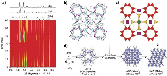
Mechanochemical LAG conversion of ZnO and HMeIm in the presence of 2.5 m acetic acid with 20 wt.% crystalline silicon as an internal scattering standard. (a) The calculated powder XRD patterns of ZIF‐8, kat‐Zn(MeIm)2, and dia‐Zn(MeIm)2 are shown above the time‐resolved diffractogram. Three characteristic ZnO reflections are marked with “#”, whereas the reflection of Si is marked with “*”. In (b) and (c) the structure of the new kat‐Zn(MeIm)2 phase is illustrated alternatively with a ball‐and‐stick representation (viewed along the crystallographic c‐direction) and the corresponding kat‐framework with different colouring for each type of vertex (vertex figure). (d) The sequence of solid‐state transformations in the LAG reaction of ZnO and HMeIm: the transformations of ZIFs resemble Ostwald's rule of stages as they follow the order of increasing T V −1 values, and hence the expected increase in the thermodynamic stability. Adapted with permission from ref. [176]. Copyright 2015 Macmillan Publishers Limited.
The success achieved in the preparation of ZIF‐type MOFs motivated other researchers in the field to accomplish more challenging preparations. For instance, inspired by the advantages of mechanochemical synthesis, Li et al. described a versatile and straightforward approach to convert a series of metal oxides supporting metal nanoparticles into composite materials with these same metal nanoparticles encapsulated (@) in a MOF matrix. [181] The study explored at first the preparation of Pd@ZIF‐8. Commercial ZnO nanopowder was combined with PdCl2 and ball‐milled. Finally, after a reduction in H2, Pd nanoparticles are formed (Figure 27). The as‐prepared Pd/ZnO was then again ball‐milled in the presence of HMeIm, NH4Cl, and ethanol to form Pd@ZIF‐8 (Figure 27). This approach proved later to be highly versatile, as Pt and Ru nanoparticles were similarly entrapped into ZIF‐8 matrices (Figure 27). Moreover, the method offers room for scale‐up (8 g of Pd@ZIF‐8 were prepared in one batch), difficult to attain by solution‐based procedures. [182] Core‐shell assemblies are not only beneficial for catalytic selectivity but also catalytic activity. [183] Remarkably, Pd@ZIF‐8 showed indeed high catalytic activity towards the selective semi‐hydrogenation of hex‐1,4‐diene to hex‐2‐ene, in contrast to Pd/ZnO, which mostly promotes complete hydrogenation to hexane. Besides, the catalyst showed improved stability, likely dependent on the confinement, which could prevent the metal nanoparticles from sintering and subsequently contribute to maintaining their dispersion and crystallinity intact.
Figure 27.

(a) TEM images of Pd/ZnO (inset, magnified view of Pd NP), (b) Pd@ZIF‐8 (inset, magnified view of Pd NP), (c) Pt@ZIF‐8 (inset, magnified view of Pt NP), and (d) Ru@ZIF‐8 (inset, magnified view of Ru NP). Adapted with permission from ref. [181]. Copyright of The Royal Society of Chemistry.
By similar means, polyoxometalates (POMs) were also successfully encapsulated in a MOF as non‐coordinating guests. POMs have lately received increasing attention as promising solid acid and oxidation catalysts, but their application is somewhat limited since the small surface areas hinder the accessibility of active sites. Up to date, the immobilization of POMs in a suitable porous matrix represents the most convenient approach to the problem, as it contributes to the isolation and dispersion of the catalytically active species. [184] Still, existing methods to encapsulate POMs in a solid matrix, such as in metal‐organic frameworks, usually suffer from high‐temperature requirements and long reaction times (e.g., solvothermal synthesis). Moreover, a large excess of active POM precursors is required to allow sufficient loading with the catalytically active species. The availability of simple, rapid, and preferably environmentally friendly synthetic strategies is thus highly desirable. Zhong et al. recently reported an efficient one‐pot mechanochemical approach to a POM@MOF (Figure 28), namely PW12@HKUST‐1 (HKUST‐1: [Cu2(BTC)4/3(H2O)2]6). [185] The material was obtained in just 5 min by simply grinding a mixture of the copper salt of PW12O40 3− and 1,3,5‐benzenetricarboxilic acid (H3BTC) in a mortar with a small amount of EtOH. (Figure 28) For comparison, [(CH3)4N]2[Cu2(BTC)4/3(H2O)2]6[HPW12O40] was obtained after a long (24 h) and cautious hydrothermal treatment of a similar mixture of components at 180 °C (Figure 28). [184] Interestingly, the polycrystalline PW12@HKUST‐1 showed high catalytic activity towards the degradation of phenol, which the authors attributed to “synergistic effects” between POM and MOF.
Figure 28.
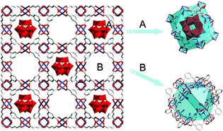
View of PW12@HKUST‐1 orthogonally to the (0 0 1) planes (A and B identify two kinds of pores). Wireframe and polyhedral models, respectively, represent the Cu‐BTC framework of HKUST‐1 and the Keggin‐type polyanion. The blue, red, and grey units in the wireframe model represent Cu, O, and C, alternately. Adapted with permission from ref. [184]. Copyright 2009 American Chemical Society.
However, it is well known that MOFs can exhibit catalytic activity by themselves. Several analogues of UiO‐66, for instance, a Zr‐containing metal‐organic framework, having exceptional chemical and thermal stability, have already been investigated as solid catalysts in a variety of reactions. [187] There are multiple ways to prepare UiO‐66 and closely related materials, but their exploitation on a large scale is hindered by the adverse nature of conventional synthesis routes. A mechanochemical approach was recently developed and will be briefly discussed in the following. [188] The method offers a nearly solvent‐free route to UiO‐type MOFs without any need for bulk solvents, aggressive reagents, or high temperatures. UiO‐66, Zr6O4(OH)4(BDC)6, was obtained as a result of the mechanochemical reaction of a carboxylate‐capped zirconium cluster (general formula: Zr6O4(OH)4(RCO2)12) and terephthalic acid (H2BDC), in the presence of a limited amount of DMF or MeOH (Figure 29). Optimized reaction parameters privileged MeOH over DMF as a process control agent and the methacrylate cluster over an alternative precursor based on benzoic acid. By this means, UiO‐66‐NH2, an isostructural MOF to UiO‐66 based on the 2‐aminoterephtalate linker, was also prepared. All the generated frameworks showed high catalytic activity in the hydrolytic degradation of nerve agent simulants, comparable to their solvothermally prepared counterparts. The synthetic procedure was further improved using water in place of methanol as the only liquid additive. The Zr6‐methacrylate cluster could be replaced by a nonconventional dodecanuclear zirconium acetate precursor, with the additional advantage of avoiding the generation of reactive and hazardous methacrylic acid by‐products. Importantly, the new reaction conditions enabled the study of a continuous mechanochemical process (known as twin‐screw extrusion, TSE) by which UiO‐66‐NH2 could be produced at a rate of almost 1.4 kg h−1 (Figure 29). [186] These results are not restricted to UiO‐type MOFs as they were also achieved in the case of three other commercially relevant MOFs (e.g., HKUST‐1, ZIF‐8, and Al(fumarate(OH))). [189]
Figure 29.
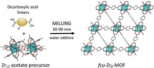
Scheme of the water‐assisted mechanochemical synthesis of Zr‐based MOF UiO‐66. Adapted with permission from ref. [186]. Copyright 2018 American Chemical Society.
Besides MOFs, mechanochemistry has also been explored to prepare closely‐related materials, such as covalent organic frameworks (COFs). [190] With the only difference of being entirely based on organic parts and covalent linkages, which provide for their low density, COFs are extended structures conceptually analogous to MOFs. COFs offer similar features as MOFs, including high surface area, hierarchical porosity, modularity, tailored functionality, moderately high chemical and mechanical robustness. [191] For these reasons, COFs are very attractive for applications in the fields of catalysis, gas storage and separation, and electronics. [192] However, the synthesis of COFs is still in its early stage of development, so that a number of questions first need to be solved. Above all, practical solutions for the mass production of COFs in an environmental‐friendly fashion have to be designed to encourage their wider application. In this context, mechanochemistry seemed to have paved the way for their scalable synthesis. An easy‐to‐perform “external coagent” (e.g., p‐toluene sulfonic acid monohydrate) assisted solid state synthesis of β‐ketoenamine linked COFs was implemented for the large‐scale synthesis of COFs (ca. 10 g h−1) in a twin‐screw extruder, which could be further extended to other systems, for instance, imine based COFs. [190] We look forward to witnessing future advances in the field.
7. Conclusions and Outlook
Mechanochemical synthesis offers a straightforward, scalable, and often more sustainable route for the synthesis of catalytic materials. Key advantages of mechanochemically‐assisted preparations include operation without a need for additives (e.g., solvents, templates, surfactants) and post‐synthetic treatments in many cases. This avoids the generation of solvent and/or gaseous wastes and simplifies the overall synthetic protocol, ultimately simplifying scale‐up. Besides, this synthetic strategy provides materials with unusual properties, which are often impossible to achieve by classical methods. Various examples described in this review demonstrate the effectiveness of the mechanochemical route for the synthesis of different kinds of catalysts, from bulk metals, single metal oxides, and multimetallic mixed oxides nanoparticles to supported metals and bimetallic alloy nanoparticles. Moreover, several of these systems have shown better performance in various catalytic applications. This progress is due to the increased interest in mechanochemistry, beyond comminution and mechanochemical alloying, and to the availability of advanced milling equipment, which allows for better control of operation parameters. However, contamination issues due to abrasion should always be kept in mind in mechanochemical processing. This is particularly critical as most of the materials used for the manufacture of milling tools and equipment typically contain elements (e.g., Fe, Ni, Cr) that are catalytically active in many reactions and can adversely influence the catalytic performance. Milling vessels and media made of ceramics might be better alternatives, but some of the ceramics contain binders, which may also be problematic for catalysis (e.g., Co in WC).
Another aspect is the scale‐up of lab‐scale catalyst syntheses. In fact, most of the examples herein discussed were attained using bench‐top shaker (mixer) mills or planetary mills, which are presently not available for large scale processing. However, some successful cases can provide some guidance in this direction. For instance, the results on the depolymerization of lignocellulose in planetary mills (1 g scale) were successfully scaled‐up to the kilogram scale in a 20 L Simoloyer device, [193] and those on the synthesis of high‐surface‐area α‐Al2O3 by dehydration of boehmite in shaker mills (1 g scale) could essentially be reproduced in 1–8 L Simoloyer devices, allowing for scale‐up up to 100–500 grams. [73] Thus, although shaker and planetary mills are not available for large‐scale applications, Simoloyers (available with vessel sizes up to 900 L) or other large‐scale high‐energy milling devices (e.g., attritors) may advantageously be used for scale‐up purposes.
In spite of tremendous success in material synthesis, the understanding of how the catalyst preparations work in ball mills is still lagging behind on the macroscopic scale. This might be due to difficulties in monitoring the synthesis progress in a non‐stationary milling vessel, in which milling media and powder are rapidly moving. For several applications, the milling vessels must be robust enough to withstand the forces and are mostly made of metals and alloys (e.g., steel alloys) or ceramics. Therefore, most kinds of radiation either cannot penetrate them or are very strongly attenuated. This makes us primarily dependent on ex situ analyses, which might not provide realistic information on intermediate states and thus hamper a complete understanding of possible reaction pathways. This notion has recently changed, thanks to the pioneering studies of Friščić and co‐workers. The group successfully designed a milling system compatible with in situ X‐ray diffraction studies directly in a synchrotron facility, which allowed monitoring the formation of a zeolitic imidazolate framework (e.g., ZIF‐8) in the ball mill.[ 177 , 194 ] Next, the group also developed an in situ Raman spectroscopy set‐up, [195] in which they broadened the scope of materials studied. [196] Recently, thermography has been added to the list of viable in situ characterization methods since the temperature development during milling was recognized as rather informative for some types of reaction. [197] However, a more innovative design of milling vessels is required to study milling processes involving hard materials (e.g., phase transformation in titania or alumina), for which plastic milling vessels are inappropriate as they cannot withstand the required high milling impacts. In this sense, some interesting concepts of milling vessels for in situ analysis are discussed by Tumanov and co‐workers. [198]
Besides catalyst synthesis, ball milling has also emerged as a highly effective tool for carrying out various catalytic reactions (e.g., organic transformations, biomass conversions, and gas‐solid reactions). Owing to the different focus of this review, this topic is not discussed herein, but it is well covered in recent reviews and a book chapter.[ 19 , 34 , 199 ] Briefly, for mechanochemically promoted catalytic reactions, milling vessels can be adapted to be used as a catalytic reactor for batch reactions. For continuous‐flow gas‐solid reactions, the vessel can be further modified to allow gas flow through and temperature monitoring at the vessel wall. [36] The positive role of ball milling in promoting catalytic reaction has long been recognized. The pioneering works in this direction were performed by Heinicke and co‐workers in the 1960s, investigating the reactions of solids with a gas phase under mechanical activation in a milling system resembling a shaker mill.[ 200 , 201 ] Afterwards, though, only a few scattered studies on gas‐solid reactions in ball mills appeared in the literature, until the last decade.[ 202 , 203 ] Indeed, recent years are witnessing a surge in interest in mechanochemistry to promote gas‐solid reactions.[ 30 , 35 , 36 , 38 , 204 ] Independently, significant progress has been made in the field of organic transformation[ 14 , 34 , 199 , 205 ] and biomass conversion.[ 206 , 207 , 208 , 209 ] Overall, we can expect more exciting developments in ball milling‐assisted processes, not only in terms of identifying new compounds, catalyst synthesis, or reactions, but also with respect to understanding the basic processes, dealing with contamination, and scale‐up aspects.
Conflict of interest
The authors declare no conflict of interest.
Biographical Information
Amol P. Amrute studied chemistry and heterogeneous catalysis at ETH Zurich, where he completed his doctorate, Dr. sc. ETH, in the group of J. Pérez‐Ramírez in 2013. After a short stay in Nexam Chemical, Sweden, he returned to ETH Zurich in 2015 as a post‐doctoral scientist. In 2018, he joined the group of F. Schüth at the Max‐Planck‐Institut für Kohlenforschung as a post‐doctoral scientist. In the current position, he is involved in the development of catalytic materials by mechanochemistry. In 2020, he joined the Institute of Chemical and Engineering Sciences, A*STAR, Singapore as Scientist.

Biographical Information
Jacopo De Bellis studied chemistry at the University of Pisa, where he completed his M. Sc. in 2018. After graduation, he joined the group of F. Schüth at the Max‐Planck‐Institut für Kohlenforschung as a doctoral student. Here, he is investigating the applications of mechanochemistry for the development of new catalytic materials, including in situ analyses of mechanocatalytic processes.

Biographical Information
Michael Felderhoff studied chemistry at the University of Essen, Germany, where he completed his doctorate in 1993 in organic chemistry. After two additional years in Essen, he carried out postdoctoral studies at the Universities of Tübingen and Osnabrück. Since 1999, he has been a member of the hydrogen storage group at the Max‐Planck‐Institut für Kohlenforschung. His research interests included mechanochemistry and the development of new metal hydride systems for hydrogen and heat storage.

Biographical Information
Ferdi Schüth studied chemistry and law at Münster University, Germany, and completed his Ph.D. in Chemistry in 1988. After a postdoctoral stay with L. D. Schmidt at the University of Minnesota, he joined the group of K. Unger in Mainz for his habilitation. In 1995 he became full professor at Frankfurt University, and in 1998 moved to Mülheim to become a director at the Max‐Planck‐Institut für Kohlenforschung. He served as vice president of the German Research Foundation (DFG) and the Max Planck Society. His research interests include catalysis, porous materials, and energy‐related topics.

Acknowledgements
Max‐Planck‐Institut für Kohlenforschung is acknowledged for financial support. Open access funding enabled and organized by Projekt DEAL.
A. P. Amrute, J. De Bellis, M. Felderhoff, F. Schüth, Chem. Eur. J. 2021, 27, 6819.
References
- 1. Fechete I., Wang Y., Védrine J. C., Catal. Today 2012, 189, 2–27. [Google Scholar]
- 2. Munnik P., de Jongh P. E., de Jong K. P., Chem. Rev. 2015, 115, 6687–6718. [DOI] [PubMed] [Google Scholar]
- 3. Copéret C., Allouche F., Chan K. W., Conley M. P., Delley M. F., Fedorov A., Moroz I. B., Mougel V., Pucino M., Searles K., Yamamoto K., Zhizhko P. A., Angew. Chem. Int. Ed. 2018, 57, 6398–6440; [DOI] [PubMed] [Google Scholar]; Angew. Chem. 2018, 130, 6506–6551. [Google Scholar]
- 4. Schüth F., Angew. Chem. Int. Ed. 2014, 53, 8599–8604; [DOI] [PubMed] [Google Scholar]; Angew. Chem. 2014, 126, 8741–8747. [Google Scholar]
- 5. Gallei M. H. E. F., Schwab E., Handbook of Heterogenous Catalysis, Wiley-VCH, Weinheim, 2008, pp. 57–66. [Google Scholar]
- 6. Keim W., Handbook of Heterogeneous Catalysis, Wiley-VCH, Weinheim, 2008, p. 2265–2274. [Google Scholar]
- 7. Ralphs K., Hardacre C., James S. L., Chem. Soc. Rev. 2013, 42, 7701–7718. [DOI] [PubMed] [Google Scholar]
- 8. Xu C., De S., Balu A. M., Ojeda M., Luque R., Chem. Commun. 2015, 51, 6698–6713. [DOI] [PubMed] [Google Scholar]
- 9. Caley E. R., Richards J. F. C., Theophrastus on Stones: Introduction, Greek Text, English Translation, and Commentary, Graduate School Monographs. Contributions, Physical Science No.1, The Ohio State University, Columbus, Ohio, 1956, p. 58. [Google Scholar]
- 10. Takacs L., Chem. Soc. Rev. 2013, 42, 7649–7659. [DOI] [PubMed] [Google Scholar]
- 11. Heinicke G., Tribochemistry, Akademie-Verlag, Berlin, 1986, p. 495. [Google Scholar]
- 12. Takacs L., J. Mater. Sci. 2004, 39, 4987–4993. [Google Scholar]
- 13. Suryanarayana C., Prog. Mater. Sci. 2001, 46, 1–184. [Google Scholar]
- 14. James S. L., Adams C. J., Bolm C., Braga D., Collier P., Friscic T., Grepioni F., Harris K. D., Hyett G., Jones W., Krebs A., Mack J., Maini L., Orpen A. G., Parkin I. P., Shearouse W. C., Steed J. W., Waddell D. C., Chem. Soc. Rev. 2012, 41, 413–447. [DOI] [PubMed] [Google Scholar]
- 15. Baláž P., Achimovičová M., Baláž M., Billik P., Cherkezova-Zheleva Z., Criado J. M., Delogu F., Dutkova E., Gaffet E., Gotor F. J., Kumar R., Mitov I., Rojac T., Senna M., Streletskii A., Wieczorek-Ciurowa K., Chem. Soc. Rev. 2013, 42, 7571–7637. [DOI] [PubMed] [Google Scholar]
- 16. Butyagin P. Y., Russ. Chem. Rev. 1984, 53, 1025–1038. [Google Scholar]
- 17. Buyanov R. A., Molchanov V. V., Boldyrev V. V., Catal. Today 2009, 144, 212–218. [Google Scholar]
- 18. Sarwat S. G., Powder Metall. 2017, 60, 267–272. [Google Scholar]
- 19. Amrute A. P., Schüth F., Catalytic Reactions in Ball Mills, The Royal Society of Chemistry, 2020. (submitted chapter). [Google Scholar]
- 20. Štefanić G., Krehula S., Štefanić I., Dalton Trans. 2015, 44, 18870–18881. [DOI] [PubMed] [Google Scholar]
- 21. Štefanić G., Krehula S., Štefanić I., Chem. Commun. 2013, 49, 9245–9247. [DOI] [PubMed] [Google Scholar]
- 22. de Macedo H. R., da Silva A. G. P., de Melo D. M. A., Mater. Lett. 2003, 57, 3924–3932. [Google Scholar]
- 23. Lukin E. S., Makarov N. A., Refract. Ind. Ceram. 1999, 40, 387–390. [Google Scholar]
- 24. Riley F. L., J. Am. Ceram. Soc. 2004, 83, 245–265. [Google Scholar]
- 25. Flegler A. J., Burye T. E., Yang Q., Nicholas J. D., Ceram. Int. 2014, 40, 16323–16335. [Google Scholar]
- 26. Tamura K., Tanaka T., Ind. Eng. Chem. Process Des. Dev. 1970, 9, 165–173. [Google Scholar]
- 27. Takacs L., McHenry J. S., J. Mater. Sci. 2006, 41, 5246–5249. [Google Scholar]
- 28. Andersen J. M., Mack J., Chem. Sci. 2017, 8, 5447–5453. [DOI] [PMC free article] [PubMed] [Google Scholar]
- 29. Andersen J., Mack J., Angew. Chem. Int. Ed. 2018, 57, 13062–13065; [DOI] [PubMed] [Google Scholar]; Angew. Chem. 2018, 130, 13246–13249. [Google Scholar]
- 30. Bilke M., Losch P., Vozniuk O., Bodach A., Schüth F., J. Am. Chem. Soc. 2019, 141, 11212–11218. [DOI] [PubMed] [Google Scholar]
- 31. Huot J., Ravnsbæk D. B., Zhang J., Cuevas F., Latroche M., Jensen T. R., Prog. Mater. Sci. 2013, 58, 30–75. [Google Scholar]
- 32. Yartys V. A., Lototskyy M. V., Akiba E., Albert R., Antonov V. E., Ares J. R., Baricco M., Bourgeois N., Buckley C. E., Bellosta von Colbe J. M., Crivello J. C., Cuevas F., Denys R. V., Dornheim M., Felderhoff M., Grant D. M., Hauback B. C., Humphries T. D., Jacob I., Jensen T. R., de Jongh P. E., Joubert J. M., Kuzovnikov M. A., Latroche M., Paskevicius M., Pasquini L., Popilevsky L., Skripnyuk V. M., Rabkin E., Sofianos M. V., Stuart A., Walker G., Wang H., Webb C. J., Zhu M., Int. J. Hydrogen Energy 2019, 44, 7809–7859. [Google Scholar]
- 33. Bellosta von Colbe J. M., Felderhoff M., Bogdanović B., Schüth F., Weidenthaler C., Chem. Commun. 2005, 4732–4734. [DOI] [PubMed] [Google Scholar]
- 34. Bolm C., Hernández J. G., Angew. Chem. Int. Ed. 2019, 58, 3285–3299; [DOI] [PubMed] [Google Scholar]; Angew. Chem. 2019, 131, 3320–3335. [Google Scholar]
- 35. Eckert R., Felderhoff M., Schüth F., Angew. Chem. Int. Ed. 2017, 56, 2445–2448; [DOI] [PubMed] [Google Scholar]; Angew. Chem. 2017, 129, 2485–2488. [Google Scholar]
- 36. Immohr S., Felderhoff M., Weidenthaler C., Schüth F., Angew. Chem. Int. Ed. 2013, 52, 12688–12691; [DOI] [PubMed] [Google Scholar]; Angew. Chem. 2013, 125, 12920–12923. [Google Scholar]
- 37. Schreyer H., Eckert R., Immohr S., de Bellis J., Felderhoff M., Schüth F., Angew. Chem. Int. Ed. 2019, 58, 11262–11265; [DOI] [PubMed] [Google Scholar]; Angew. Chem. 2019, 131, 12891. [Google Scholar]
- 38. Schreyer H., Immohr S., Schüth F., J. Mater. Sci. 2017, 52, 12021–12030. [Google Scholar]
- 39. Darr J. A., Zhang J., Makwana N. M., Weng X., Chem. Rev. 2017, 117, 11125–11238. [DOI] [PubMed] [Google Scholar]
- 40. Liu L., Corma A., Chem. Rev. 2018, 118, 4981–5079. [DOI] [PMC free article] [PubMed] [Google Scholar]
- 41. Astruc D., Chem. Rev. 2020, 120, 461–463. [DOI] [PubMed] [Google Scholar]
- 42. Amrute A. P., Łodziana Z., Schreyer H., Weidenthaler C., Schüth F., Science 2019, 366, 485–489. [DOI] [PubMed] [Google Scholar]
- 43. Chen Y., Carbon Nanotechnology, Elsevier, Amsterdam, 2006, p. 53–80. [Google Scholar]
- 44. Mukhtar N. Z. F., Borhan M. Z., Rusop M., Abdullah S., Adv. Mater. Res. 2013, 795, 711–715. [Google Scholar]
- 45. Benjamin J. S., Metall. Trans. 1970, 1, 2943–2951. [Google Scholar]
- 46. Muñoz J. E., Cervantes J., Esparza R., Rosas G., J. Nanopart. Res. 2007, 9, 945–950. [Google Scholar]
- 47. Tung D. K., Manh D. H., Phong L. T. H., Nam P. H., Nam D. N. H., Anh N. T. N., Nong H. T. T., Phan M. H., Phuc N. X., J. Electron. Mater. 2016, 45, 2644–2650. [Google Scholar]
- 48. Rajeshkanna N. O., Int. J. Sci. Eng. Res. 2014, 2, 30–35. [Google Scholar]
- 49. Yadav S. K., Int. J. Emerging Trends Sci. Technol. 2016, 3, 3795–3799. [Google Scholar]
- 50. Musza K., Szabados M., Ádám A. A., Kónya Z., Kukovecz Á., Sipos P., Pálinkó I., React. Kinet. Catal. Lett. 2019, 126, 857–868. [Google Scholar]
- 51. Kumar N., Biswas K., Gupta R. K., RSC Adv. 2016, 6, 111380–111388. [Google Scholar]
- 52. Rak M. J., Friščić T., Moores A., RSC Adv. 2016, 6, 58365–58370. [Google Scholar]
- 53. Rak M. J., Friščić T., Moores A., Faraday Discuss. 2014, 170, 155–167. [DOI] [PubMed] [Google Scholar]
- 54. Todaka Y., Mc Cormick P. G., Tsuchiya K., Umemoto M., Mater. Trans. JIM 2002, 43, 667–673. [Google Scholar]
- 55. Velasco V., Martinez A., Recio J., Hernando A., Crespo P., J. Alloys Compd. 2012, 536, S13–S16. [Google Scholar]
- 56. Aymard L., Delahaye-Vidal A., Portemer F., Disma F., J. Alloys Compd. 1996, 238, 116–127. [Google Scholar]
- 57. Delogu F., Acta Mater. 2008, 56, 2344–2352. [Google Scholar]
- 58. Guimarães J. L., Abbate M., Betim S. B., Alves M. C. M., J. Alloys Compd. 2003, 352, 16–20. [Google Scholar]
- 59. Chauruka S. R., Hassanpour A., Brydson R., Roberts K. J., Ghadiri M., Stitt H., Chem. Eng. Sci. 2015, 134, 774–783. [Google Scholar]
- 60. Pan X., Ma X., J. Solid State Chem. 2004, 177, 4098–4103. [Google Scholar]
- 61. Zieliński P. A., Schulz R., Kaliaguine S., Van Neste A., J. Mater. Res. 1993, 8, 2985–2992. [Google Scholar]
- 62. Pu S., Li L., Ma J., Lu F., Li J., Sci. Rep. 2015, 5, 11575. [DOI] [PMC free article] [PubMed] [Google Scholar]
- 63. Yang Y., Zhang S., Wang S., Zhang K., Wang H., Huang J., Deng S., Wang B., Wang Y., Yu G., Environ. Sci. Technol. 2015, 49, 4473–4480. [DOI] [PubMed] [Google Scholar]
- 64. Zhang Z., Yang S., Hu X., Xu H., Peng H., Liu M., Thapaliya B. P., Jie K., Zhao J., Liu J., Chen H., Leng Y., Lu X., Fu J., Zhang P., Dai S., Chem. Mater. 2019, 31, 5529–5536. [Google Scholar]
- 65. Goyal R. K., Deshpande S. P., Singare S. S., J. Mater. Sci. Surf. Eng. 2016, 4, 360–363. [Google Scholar]
- 66. Zakeri M., Razavi M., Rahimipour M. R., Jamal Abbasi B., Physica B 2014, 444, 49–53. [Google Scholar]
- 67. Laine R. M., Marchal J. C., Sun H. P., Pan X. Q., Nat. Mater. 2006, 5, 710–712. [DOI] [PubMed] [Google Scholar]
- 68. McHale J. M., Auroux A., Perrotta A. J., Navrotsky A., Science 1997, 277, 788–791. [Google Scholar]
- 69.A. K. Garg, Fine Alpha Alumina Particles, Their Production and Use, European Patent (EP0554908B1) 1996.
- 70. Li L., Pu S., Liu Y., Zhao L., Ma J., Li J., Adv. Powder Technol. 2018, 29, 2194–2203. [Google Scholar]
- 71. Ma H. W., Krell A., Key Eng. Mater. 2001, 206–213, 43–46. [Google Scholar]
- 72. Tonejc A., Tonejc A. M., Bagović D., Kosanović C., Mater. Sci. Eng. A 1994, 181–182, 1227–1231. [Google Scholar]
- 73.A. P. Amrute, F. Schüth, 2020 unpublished results.
- 74. Amrute A. P., Jeske K., Łodziana Z., Prieto G., Schüth F., Chem. Mater. 2020, 32, 4369–4374. [Google Scholar]
- 75. Zhao L.-Y., Dong X.-L., Lu A.-H., ChemPlusChem 2020, 85, 866–875. [DOI] [PubMed] [Google Scholar]
- 76. Zhang P., Wang L., Yang S., Schott J. A., Liu X., Mahurin S. M., Huang C., Zhang Y., Fulvio P. F., Chisholm M. F., Dai S., Nat. Commun. 2017, 8, 15020. [DOI] [PMC free article] [PubMed] [Google Scholar]
- 77. Hansen T. W., DeLaRiva A. T., Challa S. R., Datye A. K., Acc. Chem. Res. 2013, 46, 1720–1730. [DOI] [PubMed] [Google Scholar]
- 78. Amrute A. P., Zibrowius B., Schüth F., Chem. Mater. 2020, 32, 4699–4706. [Google Scholar]
- 79. Lin Y., Watson K. A., Fallbach M. J., Ghose S., Smith J. G., Delozier D. M., Cao W., Crooks R. E., Connell J. W., ACS Nano 2009, 3, 871–884. [DOI] [PubMed] [Google Scholar]
- 80. Lin Y., Watson K. A., Ghose S., Smith J. G., Williams T. V., Crooks R. E., Cao W., Connell J. W., J. Phys. Chem. C 2009, 113, 14858–14862. [Google Scholar]
- 81. Georgakilas V., Gournis D., Tzitzios V., Pasquato L., Guldi D. M., Prato M., J. Mater. Chem. 2007, 17, 2679–2694. [Google Scholar]
- 82. Forró L., Gaal R., Grimaldi C., Mionić M., Ribič P. R., Smajda R., Magrez A., AIP Adv. 2013, 3, 092117. [Google Scholar]
- 83. Siamaki A. R., Lin Y., Woodberry K., Connell J. W., Gupton B. F., J. Mater. Chem. A 2013, 1, 12909–12918. [Google Scholar]
- 84. Kondrat S. A., Shaw G., Freakley S. J., He Q., Hampton J., Edwards J. K., Miedziak P. J., Davies T. E., Carley A. F., Taylor S. H., Kiely C. J., Hutchings G. J., Chem. Sci. 2012, 3, 2965–2971. [Google Scholar]
- 85. Kung H. H., Kung M. C., Costello C. K., J. Catal. 2003, 216, 425–432. [Google Scholar]
- 86. Danielis M., Colussi S., de Leitenburg C., Soler L., Llorca J., Trovarelli A., Angew. Chem. Int. Ed. 2018, 57, 10212–10216; [DOI] [PubMed] [Google Scholar]; Angew. Chem. 2018, 130, 10369–10373. [Google Scholar]
- 87. Danielis M., Colussi S., de Leitenburg C., Soler L., Llorca J., Trovarelli A., Catal. Sci. Technol. 2019, 9, 4232–4238. [Google Scholar]
- 88. Danielis M., Colussi S., de Leitenburg C., Trovarelli A., Catal. Commun. 2020, 135, 105899. [Google Scholar]
- 89.J. De Bellis, M. Felderhoff, F. Schüth, Unpublished results.
- 90. He X., Deng Y., Zhang Y., He Q., Xiao D., Peng M., Zhao Y., Zhang H., Luo R., Gan T., Ji H., Ma D., Cell Rep. Phys. Sci. 2020, 1, 100004. [Google Scholar]
- 91. Gan T., He Q., Zhang H., Xiao H., Liu Y., Zhang Y., He X., Ji H., Chem. Eng. J. 2020, 389, 124490. [Google Scholar]
- 92. Kamolphop U., Taylor S. F. R., Breen J. P., Burch R., Delgado J. J., Chansai S., Hardacre C., Hengrasmee S., James S. L., ACS Catal. 2011, 1, 1257–1262. [Google Scholar]
- 93. Ralphs K., D′Agostino C., Burch R., Chansai S., Gladden L. F., Hardacre C., James S. L., Mitchell J., Taylor S. F. R., Catal. Sci. Technol. 2014, 4, 531–539. [Google Scholar]
- 94. Ralphs K., Chansai S., Hardacre C., Burch R., Taylor S. F. R., James S. L., Catal. Today 2015, 246, 198–206. [Google Scholar]
- 95. Firsova A. A., Morozova O. S., Leonov A. V., Streletskii A. N., Korchak V. N., Kinet. Catal. 2014, 55, 777–785. [Google Scholar]
- 96. Meng X., Bi X., Yu C., Chen G., Chen B., Jing Z., Zhao P., Green Chem. 2018, 20, 4638–4644. [Google Scholar]
- 97. Pineda A., Balu A. M., Campelo J. M., Romero A. A., Carmona D., Balas F., Santamaria J., Luque R., ChemSusChem 2011, 4, 1561–1565. [DOI] [PubMed] [Google Scholar]
- 98. Pineda A., Ojeda M., Romero A. A., Balu A. M., Luque R., Microporous Mesoporous Mater. 2018, 272, 129–136. [Google Scholar]
- 99. Pineda A., Lázaro N., Balu A. M., Garcia A., Romero A. A., Luque R., Mol. Catal. 2020, 493, 111092. [Google Scholar]
- 100. Amrute A. P., Larrazábal G. O., Mondelli C., Pérez-Ramírez J., Angew. Chem. Int. Ed. 2013, 52, 9772–9775; [DOI] [PubMed] [Google Scholar]; Angew. Chem. 2013, 125, 9954–9957. [Google Scholar]
- 101. Zhao Q., Yan Z., Chen C., Chen J., Chem. Rev. 2017, 117, 10121–10211. [DOI] [PubMed] [Google Scholar]
- 102. Kaczmarczyk J., Zasada F., Janas J., Indyka P., Piskorz W., Kotarba A., Sojka Z., ACS Catal. 2016, 6, 1235–1246. [Google Scholar]
- 103. Obalová L., Karásková K., Jirátová K., Kovanda F., Appl. Catal. B 2009, 90, 132–140. [Google Scholar]
- 104. PalDey S., Gedevanishvili S., Zhang W., Rasouli F., Appl. Catal. B 2005, 56, 241–250. [Google Scholar]
- 105. Wang S., Ding Z., Wang X., Chem. Commun. 2015, 51, 1517–1519. [DOI] [PubMed] [Google Scholar]
- 106. Kang D., Kim T. W., Kubota S. R., Cardiel A. C., Cha H. G., Choi K.-S., Chem. Rev. 2015, 115, 12839–12887. [DOI] [PubMed] [Google Scholar]
- 107. Liang Y., Li Y., Wang H., Zhou J., Wang J., Regier T., Dai H., Nat. Mater. 2011, 10, 780–786. [DOI] [PubMed] [Google Scholar]
- 108. Cheng F., Shen J., Peng B., Pan Y., Tao Z., Chen J., Nat. Chem. 2011, 3, 79–84. [DOI] [PubMed] [Google Scholar]
- 109. Anu Prathap M. U., Srivastava R., Nano Energy 2013, 2, 1046–1053. [Google Scholar]
- 110. Sun S., Zhou Y., Hu B., Zhang Q., Xu Z. J., J. Electrochem. Soc. 2016, 163, H99–H104. [Google Scholar]
- 111. Dodd A., McKinley A., Tsuzuki T., Saunders M., J. Eur. Ceram. Soc. 2009, 29, 139–144. [Google Scholar]
- 112. Domanski D., Urretavizcaya G., Castro F. J., Gennari F. C., J. Am. Ceram. Soc. 2005, 87, 2020–2024. [Google Scholar]
- 113. Fabián M., Bottke P., Girman V., Düvel A., Da Silva K. L., Wilkening M., Hahn H., Heitjans P., Šepelák V., RSC Adv. 2015, 5, 54321–54328. [Google Scholar]
- 114. Lazarević Z. Ž., Jovalekić Č., Milutinović A., Sekulić D., Slankamenac M., Romčević M., Romčević N. Ž., Ferroelectrics 2013, 448, 1–11. [Google Scholar]
- 115. Mancheva M., Iordanova R., Dimitriev Y., J. Alloys Compd. 2011, 509, 15–20. [Google Scholar]
- 116. Manova E., Kunev B., Paneva D., Mitov I., Petrov L., Estournès C., D′Orléan C., Rehspringer J.-L., Kurmoo M., Chem. Mater. 2004, 16, 5689–5696. [Google Scholar]
- 117. Manova E., Paneva D., Kunev B., Estournès C., Rivière E., Tenchev K., Léaustic A., Mitov I., J. Alloys Compd. 2009, 485, 356–361. [Google Scholar]
- 118. Rahmanivahid B., Pinilla-de Dios M., Haghighi M., Luque R., Molecules 2019, 24, 2597. [DOI] [PMC free article] [PubMed] [Google Scholar]
- 119. Lazarević Z. Ž., Jovalekić Č., Milutinović A., Sekulić D., Ivanovski V. N., Rečnik A., Cekić B., Romčević N. Ž., J. Appl. Phys. 2013, 113, 187221. [Google Scholar]
- 120. Tejuca L. G., Fierro J. L. G., Properties and Applications of Perovskite-Type Oxides, CRC, Boca Raton, 1992, p. 400. [Google Scholar]
- 121. Voorhoeve R. J. H., Remeika J. P., Freeland P. E., Matthias B. T., Science 1972, 177, 353–354. [DOI] [PubMed] [Google Scholar]
- 122. Jacobson A. J., Chem. Mater. 2010, 22, 660–674. [Google Scholar]
- 123. Miao X., Wu L., Lin Y., Yuan X., Zhao J., Yan W., Zhou S., Shi L., Chem. Commun. 2019, 55, 1442–1445. [DOI] [PubMed] [Google Scholar]
- 124. Wang W., Xu M., Xu X., Zhou W., Shao Z., Angew. Chem. Int. Ed. 2020, 59, 136–152; [DOI] [PubMed] [Google Scholar]; Angew. Chem. 2020, 132, 140–158. [Google Scholar]
- 125. Crespin M., Hall W. K., J. Catal. 1981, 69, 359–370. [Google Scholar]
- 126. Kaliaguine S., Van Neste A., Szabo V., Gallot J. E., Bassir M., Muzychuk R., Appl. Catal. A 2001, 209, 345–358. [Google Scholar]
- 127. Royer S., Bérubé F., Kaliaguine S., Appl. Catal. A 2005, 282, 273–284. [Google Scholar]
- 128. Szabo V., Bassir M., Van Neste A., Kaliaguine S., Appl. Catal. B 2002, 37, 175–180. [Google Scholar]
- 129. Zhang R., Alamdari H., Kaliaguine S., Appl. Catal. A 2008, 340, 140–151. [Google Scholar]
- 130. Zhang R., Villanueva A., Alamdari H., Kaliaguine S., Appl. Catal. B 2006, 64, 220–233. [Google Scholar]
- 131. Zhang R., Villanueva A., Alamdari H., Kaliaguine S., J. Catal. 2006, 237, 368–380. [Google Scholar]
- 132. Zhang R., Villanueva A., Alamdari H., Kaliaguine S., J. Mol. Catal. 2006, 258, 22–34. [Google Scholar]
- 133. Zhang R., Villanueva A., Alamdari H., Kaliaguine S., Appl. Catal. A 2006, 307, 85–97. [Google Scholar]
- 134. Heidinger B., Royer S., Alamdari H., Giraudon J.-M., Lamonier J.-F., Catalysts 2019, 9, 633. [Google Scholar]
- 135. Petrović S., Terlecki-Baričević A., Karanović L., Kirilov-Stefanov P., Zdujić M., Dondur V., Paneva D., Mitov I., Rakić V., Appl. Catal. B 2008, 79, 186–198. [Google Scholar]
- 136. Uchiyama T., Nishibori M., Einaga H., Teraoka Y., Krehula S., J. Am. Ceram. Soc. 2015, 98, 1047–1051. [Google Scholar]
- 137. Kesić Ž., Lukić I., Zdujić M., Jovalekić Č., Veljković V., Skala D., Fuel Process. Technol. 2016, 143, 162–168. [Google Scholar]
- 138. Piotr D., Wojciech B., Krystyna W.-C., Czesław K., Materials Science-Poland 2013, 31, 462–470. [Google Scholar]
- 139. Rahangdale K. K., Ganguly S., IOP Conf. Ser.: Mater. Sci. Eng. 2019, 577, 012162. [Google Scholar]
- 140. Karmakar A., Dodd M. S., Zhang X., Oakley M. S., Klobukowski M., Michaelis V. K., Chem. Commun. 2019, 55, 5079–5082. [DOI] [PubMed] [Google Scholar]
- 141. Manukyan K. V., Yeghishyan A. V., Moskovskikh D. O., Kapaldo J., Mintairov A., Mukasyan A. S., J. Mater. Sci. 2016, 51, 9123–9130. [Google Scholar]
- 142. Gawande M. B., Pandey R. K., Jayaram R. V., Catal. Sci. Technol. 2012, 2, 1113–1125. [Google Scholar]
- 143. Juma A. O., Arbab E. A. A., Muiva C. M., Lepodise L. M., Mola G. T., J. Alloys Compd. 2017, 723, 866–872. [Google Scholar]
- 144. Dodd A., McKinley A., Saunders M., Tsuzuki T., Nanotechnology 2006, 17, 692–698. [Google Scholar]
- 145. Ghorai T. K., Chakraborty M., Pramanik P., J. Alloys Compd. 2011, 509, 8158–8164. [Google Scholar]
- 146. Subramonian W., Wu T. Y., Chai S.-P., J. Alloys Compd. 2017, 695, 496–507. [Google Scholar]
- 147. Basnet P., Anderson E., Zhao Y., ACS Appl. Nano Mater. 2019, 2, 2446–2455. [Google Scholar]
- 148. Ilyin A. A., Rumyantsev R. N., Zhukov A. B., Ilyin A. P., Nanotechnol. Russ. 2016, 11, 569–578. [Google Scholar]
- 149. Knauss M., Tolea F., Valeanu M., Diamandescu L., Trotta R., Wood K., Grabias A., Sorescu M., J. Miner. Mater. Charact. Eng. 2018, 6, 587–600. [Google Scholar]
- 150. Borchers C., Martin M. L., Vorobjeva G. A., Morozova O. S., Firsova A. A., Leonov A. V., Kurmaev E. Z., Kukharenko A. I., Zhidkov I. S., Cholakh S. O., AIP Adv. 2019, 9, 065115. [Google Scholar]
- 151. The Luong N., Okumura H., Yamasue E., Ishihara K. N., Royal Soc. Open Sci. 2019, 6, 181861. [DOI] [PMC free article] [PubMed] [Google Scholar]
- 152. Zhu Y., Ling Q., Liu Y., Wang H., Zhu Y., Phys. Chem. Chem. Phys. 2015, 17, 933–940. [DOI] [PubMed] [Google Scholar]
- 153. Chen G., Li D., Li F., Fan Y., Zhao H., Luo Y., Yu R., Meng Q., Appl. Catal. A 2012, 443–444, 138–144. [Google Scholar]
- 154. Liu Q., Pu Z., Asiri A. M., Qusti A. H., Al-Youbi A. O., Sun X., J. Nanopart. Res. 2013, 15, 2057. [Google Scholar]
- 155. Zong X., Yan H., Wu G., Ma G., Wen F., Wang L., Li C., J. Am. Chem. Soc. 2008, 130, 7176–7177. [DOI] [PubMed] [Google Scholar]
- 156. Asahi R., Morikawa T., Ohwaki T., Aoki K., Taga Y., Science 2001, 293, 269–271. [DOI] [PubMed] [Google Scholar]
- 157. Shifu C., Lei C., Shen G., Gengyu C., Chem. Phys. Lett. 2005, 413, 404–409. [Google Scholar]
- 158. Tang Y.-C., Huang X.-H., Yu H.-Q., Tang L.-H., Int. J. Photoenergy 2012, 2012, 960726. [Google Scholar]
- 159. Yin S., Solid State Ionics 2004, 172, 205–209. [Google Scholar]
- 160. Yin S., Yamaki H., Komatsu M., Zhang Q., Wang J., Tang Q., Saito F., Sato T., J. Mater. Chem. 2003, 13, 2996–3001. [Google Scholar]
- 161. Amrute A. P., Mondelli C., Moser M., Novell-Leruth G., López N., Rosenthal D., Farra R., Schuster M. E., Teschner D., Schmidt T., Pérez-Ramírez J., J. Catal. 2012, 286, 287–297. [Google Scholar]
- 162. Montini T., Melchionna M., Monai M., Fornasiero P., Chem. Rev. 2016, 116, 5987–6041. [DOI] [PubMed] [Google Scholar]
- 163. Carbajal-Ramos I. A., Gomez M. F., Condó A. M., Bengió S., Andrade-Gamboa J. J., Abello M. C., Gennari F. C., Appl. Catal. B 2016, 181, 58–70. [Google Scholar]
- 164. Morozova L. V., Lapshin A. E., Panova T. I., Glushkova V. B., Inorg. Mater. 2002, 38, 153–158. [Google Scholar]
- 165. Shah P. M., Burnett J. W. H., Morgan D. J., Davies T. E., Taylor S. H., Catalysts 2019, 9, 475. [Google Scholar]
- 166. Shah P. M., Day A. N., Davies T. E., Morgan D. J., Taylor S. H., Appl. Catal. B 2019, 253, 331–340. [Google Scholar]
- 167. Nicole L., Laberty-Robert C., Rozes L., Sanchez C., Nanoscale 2014, 6, 6267–6292. [DOI] [PubMed] [Google Scholar]
- 168. Sanchez C., Belleville P., Popall M., Nicole L., Chem. Soc. Rev. 2011, 40, 696–753. [DOI] [PubMed] [Google Scholar]
- 169. Shylesh S., Jia M., Thiel W. R., Eur. J. Inorg. Chem. 2010, 4395–4410. [Google Scholar]
- 170. Yaghi O. M., Kalmutzki M. J., Diercks C. S., Introduction to Reticular Chemistry: Metal-Organic Frameworks and Covalent Organic Frameworks, Wiley-VCH, Weinheim, 2019, pp. 57–81. [Google Scholar]
- 171. Furukawa H., Cordova K. E., O'Keeffe M., Yaghi O. M., Science 2013, 341, 1230444. [DOI] [PubMed] [Google Scholar]
- 172. Huskić I., Friščić T., Philos. Trans. R. Soc. A 2019, 377, 20180221. [DOI] [PMC free article] [PubMed] [Google Scholar]
- 173. Tanaka S., Kida K., Nagaoka T., Ota T., Miyake Y., Chem. Commun. 2013, 49, 7884–7886. [DOI] [PubMed] [Google Scholar]
- 174. Friščić T., Reid D. G., Halasz I., Stein R. S., Dinnebier R. E., Duer M. J., Angew. Chem. Int. Ed. 2010, 49, 712–715; [DOI] [PubMed] [Google Scholar]; Angew. Chem. 2010, 122, 724–727. [Google Scholar]
- 175. Beldon P. J., Fábián L., Stein R. S., Thirumurugan A., Cheetham A. K., Friščić T., Angew. Chem. Int. Ed. 2010, 49, 9640–9643; [DOI] [PubMed] [Google Scholar]; Angew. Chem. 2010, 122, 9834–9837. [Google Scholar]
- 176. Katsenis A. D., Puskaric A., Strukil V., Mottillo C., Julien P. A., Uzarevic K., Pham M. H., Do T. O., Kimber S. A., Lazic P., Magdysyuk O., Dinnebier R. E., Halasz I., Friscic T., Nat. Commun. 2015, 6, 6662. [DOI] [PubMed] [Google Scholar]
- 177. Friščić T., Halasz I., Beldon P. J., Belenguer A. M., Adams F., Kimber S. A. J., Honkimäki V., Dinnebier R. E., Nat. Chem. 2013, 5, 66–73. [DOI] [PubMed] [Google Scholar]
- 178. Julien P. A., Užarević K., Katsenis A. D., Kimber S. A. J., Wang T., Farha O. K., Zhang Y., Casaban J., Germann L. S., Etter M., Dinnebier R. E., James S. L., Halasz I., Friščić T., J. Am. Chem. Soc. 2016, 138, 2929–2932. [DOI] [PubMed] [Google Scholar]
- 179. Stolar T., Batzdorf L., Lukin S., Žilić D., Motillo C., Friščić T., Emmerling F., Halasz I., Užarević K., Inorg. Chem. 2017, 56, 6599–6608. [DOI] [PubMed] [Google Scholar]
- 180. Germann L. S., Katsenis A. D., Huskić I., Julien P. A., Užarević K., Etter M., Farha O. K., Friščić T., Dinnebier R. E., Cryst. Growth Des. 2020, 20, 49–54. [Google Scholar]
- 181. Li X., Zhang Z., Xiao W., Deng S., Chen C., Zhang N., J. Mater. Chem. A 2019, 7, 14504–14509. [Google Scholar]
- 182. Yang Q., Xu Q., Jiang H.-L., Chem. Soc. Rev. 2017, 46, 4774–4808. [DOI] [PubMed] [Google Scholar]
- 183. Yang Q., Liu W., Wang B., Zhang W., Zeng X., Zhang C., Qin Y., Sun X., Wu T., Liu J., Huo F., Lu J., Nat. Commun. 2017, 8, 14429. [DOI] [PMC free article] [PubMed] [Google Scholar]
- 184. Sun C.-Y., Liu S.-X., Liang D.-D., Shao K.-Z., Ren Y.-H., Su Z.-M., J. Am. Chem. Soc. 2009, 131, 1883–1888. [DOI] [PubMed] [Google Scholar]
- 185. Zhong X., Lu Y., Luo F., Liu Y., Li X., Liu S., Chem. Eur. J. 2018, 24, 3045–3051. [DOI] [PubMed] [Google Scholar]
- 186. Karadeniz B., Howarth A. J., Stolar T., Islamoglu T., Dejanović I., Tireli M., Wasson M. C., Moon S.-Y., Farha O. K., Friščić T., Užarević K., ACS Sustainable Chem. Eng. 2018, 6, 15841–15849. [Google Scholar]
- 187. Howarth A. J., Liu Y., Li P., Li Z., Wang T. C., Hupp J. T., Farha O. K., Nat. Rev. Mater. 2016, 1, 15018. [Google Scholar]
- 188. Užarević K., Wang T. C., Moon S.-Y., Fidelli A. M., Hupp J. T., Farha O. K., Friščić T., Chem. Commun. 2016, 52, 2133–2136. [DOI] [PMC free article] [PubMed] [Google Scholar]
- 189. Crawford D., Casaban J., Haydon R., Giri N., McNally T., James S. L., Chem. Sci. 2015, 6, 1645–1649. [DOI] [PMC free article] [PubMed] [Google Scholar]
- 190. Kandambeth S., Dey K., Banerjee R., J. Am. Chem. Soc. 2019, 141, 1807–1822. [DOI] [PubMed] [Google Scholar]
- 191. Diercks C. S., Yaghi O. M., Science 2017, 355, eaal1585. [DOI] [PubMed] [Google Scholar]
- 192. Zhao W., Xia L., Liu X., CrystEngComm 2018, 20, 1613–1634. [Google Scholar]
- 193. Kaufman Rechulski M. D., Käldström M., Richter U., Schüth F., Rinaldi R., Ind. Eng. Chem. Res. 2015, 54, 4581–4592. [Google Scholar]
- 194. Halasz I., Kimber S. A. J., Beldon P. J., Belenguer A. M., Adams F., Honkimäki V., Nightingale R. C., Dinnebier R. E., Friščić T., Nat. Protoc. 2013, 8, 1718–1729. [DOI] [PubMed] [Google Scholar]
- 195. Gracin D., Štrukil V., Friščić T., Halasz I., Užarević K., Angew. Chem. Int. Ed. 2014, 53, 6193–6197; [DOI] [PubMed] [Google Scholar]; Angew. Chem. 2014, 126, 6307–6311. [Google Scholar]
- 196. Užarević K., Halasz I., Friščić T., J. Phys. Chem. Lett. 2015, 6, 4129–4140. [DOI] [PubMed] [Google Scholar]
- 197. Kulla H., Haferkamp S., Akhmetova I., Röllig M., Maierhofer C., Rademann K., Emmerling F., Angew. Chem. Int. Ed. 2018, 57, 5930–5933; [DOI] [PubMed] [Google Scholar]; Angew. Chem. 2018, 130, 6034–6038. [Google Scholar]
- 198. Tumanov N., Ban V., Poulain A., Filinchuk Y., J. Appl. Crystallogr. 2017, 50, 994–999. [Google Scholar]
- 199. Stolle A., Szuppa T., Leonhardt S. E. S., Ondruschka B., Chem. Soc. Rev. 2011, 40, 2317–2329. [DOI] [PubMed] [Google Scholar]
- 200. Heinicke G., Z. Anorg. Allg. Chem. 1963, 324, 173–184. [Google Scholar]
- 201. Heinicke G., Sigrist K., Z. Anorg. Allg. Chem. 1967, 350, 148. [Google Scholar]
- 202. Mori S., Xu W. C., Ishidzuki T., Ogasawara N., Imai J., Kobayashi K., Appl. Catal. A 1996, 137, 255–268. [Google Scholar]
- 203. Mulas G., Campesi R., Garroni S., Delogu F., Milanese C., Appl. Surf. Sci. 2011, 257, 8165–8170. [Google Scholar]
- 204. Chistovalov S. M., Kotov V. M., Anisimov A. A., Temnikov M. N., Zhemchugov P. V., Muzafarov A. M., Chem. Pet. Eng. 2019, 54, 703–707. [Google Scholar]
- 205. Rodríguez B., Bruckmann A., Rantanen T., Bolm C., Adv. Synth. Catal. 2007, 349, 2213–2233. [Google Scholar]
- 206. Hick S. M., Griebel C., Restrepo D. T., Truitt J. H., Buker E. J., Bylda C., Blair R. G., Green Chem. 2010, 12, 468–474. [Google Scholar]
- 207. Hilgert J., Meine N., Rinaldi R., Schüth F., Energy Environ. Sci. 2013, 6, 92–96. [Google Scholar]
- 208. Meine N., Rinaldi R., Schüth F., ChemSusChem 2012, 5, 1449–1454. [DOI] [PubMed] [Google Scholar]
- 209. Schüth F., Rinaldi R., Meine N., Käldström M., Hilgert J., Rechulski M. D. K., Catal. Today 2014, 234, 24–30. [Google Scholar]


