Abstract
The electrocatalytic transformation of carbon dioxide has been a topic of interest in the field of CO2 utilization for a long time. Recently, the area has seen increasing dynamics as an alternative strategy to catalytic hydrogenation for CO2 reduction. While many studies focus on the direct electron transfer to the CO2 molecule at the electrode material, molecular transition metal complexes in solution offer the possibility to act as catalysts for the electron transfer. C1 compounds such as carbon monoxide, formate, and methanol are often targeted as the main products, but more elaborate transformations are also possible within the coordination sphere of the metal center. This perspective article will cover selected examples to illustrate and categorize the currently favored mechanisms for the electrochemically induced transformation of CO2 promoted by homogeneous transition metal complexes. The insights will be corroborated with the concepts and elementary steps of organometallic catalysis to derive potential strategies to broaden the molecular diversity of possible products.
Keywords: carbon dioxide, electrocatalysis, homogeneous (molecular) catalysis, reduction, transition metals
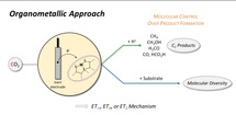
This review article illustrates and categorizes the currently favored molecular mechanisms for the electrochemically induced transformation of CO2 promoted by homogeneous transition metal complexes. The resulting insights are corroborated by the concepts and elementary steps of organometallic catalysis to derive strategies to broaden the molecular diversity of products.
1. Background and Motivation
Nature, in one of its greatest masterpieces, uses carbon dioxide via photosynthesis to produce organic matter and oxygen, whereas respiration consumes oxygen and releases CO2. The atmospheric levels of CO2 were almost constant at approximately 280 ppm during most of humankind's history. [1] With the start of the industrial revolution, the welfare of an ever‐growing population could be improved through the exploitation of fossil resources for energy generation, [2] production of nutrients/fertilizers, [3] transport and aviation, [4] construction industry, [5] and chemical production. [6] However, as carbon dioxide is the ultimate product of all processes involving oxidation of carbon, these anthropogenic value chains are reversing nature's synthetic efforts. Huge amounts of carbon deposited over millions of years are now released on a time scale of decades or even years, resulting in a perturbation of the carbon balance on this planet.[ 4a , 7 ] Currently, the concentrations of CO2 in the atmosphere determined at Mauna Loa Observatory (Hawaii) are exceeding 415 ppm, [8] and natural consumption solely is no longer expected to decrease these values. [9] Acting as a greenhouse gas, carbon dioxide levels have a direct impact on global warming, sea levels, ocean acidification, biodiversity, and other environmental burdens. [10] Global awareness of the necessity to take action results in highly dynamic political, societal, and economic developments. Ultimately, the transition from the “fossil age” to a sustainable low‐carbon economy can be enabled only by scientific progress and technological innovation to reduce the carbon footprint. Among these attempts, the transformation of CO2 into valuable molecules by using renewable—and thus carbon‐free—primary energy generation (e.g., wind, water, or solar power) constitutes a promising approach. [11] The concept of Power‐to‐X (Figure 1) stipulates the synthesis of chemical energy carriers or products via effective and scalable technologies based on chemical, biochemical, and electrochemical transformations as well as combinations thereof. [12] In the resulting system, energy can be stored, used, and harvested in molecules ranging from hydrocarbons to simple C1 compounds (e.g., formic acid or methanol), complex functional materials and even fine chemicals or pharmaceutical products. [13]
Figure 1.
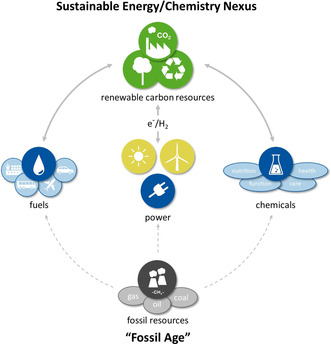
From the “fossil age” to a sustainable energy and chemistry nexus based on Power‐to‐X technologies.
For the foreseeable future, large amounts of CO2 are available as potential feedstocks from various industrial processes in high concentration. [14] Even in long‐term scenarios, if full decarbonization of all non‐chemical sectors would be achieved, the carbon reserves in the various forms of CO2 (e.g., in the atmosphere, hydrosphere, and carbonates in the terrestrial environment) considerably exceed those of fossil resources. [15] Consequently, the conversion of carbon dioxide into fuels, basic and fine chemicals, as well as polymer materials offers tremendous potential to utilize carbon‐free electricity from increasingly deployed renewable energy technologies in chemical added‐value chains. [16] In addition to low‐carbon paths to existing products, this can even allow the design of new products with improved properties comprising the concepts of green chemistry. [17]
The sun is an almost inexhaustible energy source for our planet and can be exploited in many ways and various forms for the generation of renewable electricity. [18] Depending on the regional and climatic situations, there are different preferred technological options for renewable energy. Hence, in Europe, wind energy can foreseeably be captured most efficiently in the northern parts, while solar energy could come preferentially from areas in the south (Figure 2). Irrespective of the preferred technology, the generation of electricity (“power”) is intermittent and fluctuating, and thus requires efficient and flexible storage technologies. Also, in this context, its conversion into molecular energy carriers or chemical products offers an attractive possibility to balance supply and demand. [19]
Figure 2.
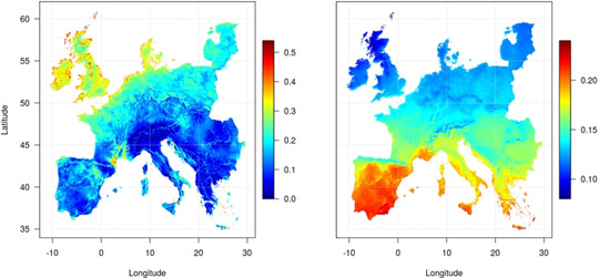
Average capacity factors for wind (left) and photovoltaics (right) in Europe (1995–2015). Reprinted from ref. [20] with permission.
The most direct synthetically useful interconversion of electrons and chemical bonds seems to be provided by electrochemistry, based on historical developments such as Faraday's pioneering work, [21] the Kolbe electrolysis, [22] and the Tafel rearrangement. [23] While synthetic electrochemistry is sometimes perceived as a rather complicated technology due to the challenges of controlling the many system parameters on a laboratory scale (i.e., electrodes, electrolytes, cells, solvent, etc.), [24] industrial processes including the chloralkali [25] or Hall–Héroult [26] electrolysis as well as the Baizer–Monsanto process [27] are currently used to produce millions of tons of valuable chemicals. Recent developments in synthetic organic chemistry illustrate the potential of preparative electrolysis to become part of the toolbox for manipulating molecular complexity. [28] This is particularly true for transformations involving molecular mediators or catalysts to orchestrate the combination of electron transfer and bond formations.
Since the 1970s, many scientific breakthroughs and developments have proved that catalytically active transition metal catalysts can convert CO2 into more valuable chemicals via thermochemical routes.[ 15 , 29 ] While industrial implementation is already pursued in individual cases, [30] the broad application of this strategy still faces significant challenges. These include: 1) high costs inherent to the capture, purification, storage, and transport of carbon dioxide to the processing sites; 2) high energy requirements for the conversion of CO2; and 3) limited diversity of CO2‐based chemicals, resulting in 4) limited market size, industrial investments, and insufficient socio‐economical demand. [31]
A possible approach to address these challenges could be provided by electrocatalytic (inter)conversion of electrical power into chemical bonds. While challenge 1 is independent of the method of chemical conversion, electrocatalysis can provide innovative solutions concerning the issues of energy efficiency (challenge 2) and chemical diversity (challenge 3). These aspects reflect the main motivation defining the scope of this article. Overcoming these hurdles will ultimately impact challenge 4, where the development of greener methodologies for CO2 conversion would substitute conventional, less environmentally benign synthetic routes.
At a fundamental level, the thermodynamic stability and kinetic inertness of the CO2 molecule constitute the central challenges for Power‐to‐X strategies. [32] Its conversion to valuable C1 chemicals and more sophisticated products requires a combination of reduction (addition of electrons) and bond‐forming (addition of protons and/or other reagents) processes (Figure 3). While the reduction along the C1 pathway (diagonal) leads to individual products with very high potential production volumes, the molecular diversity space at each level (horizontal) offers a large number of possibilities to realize combined economic and ecologic benefits as compared to today's value chains. [33]
Figure 3.
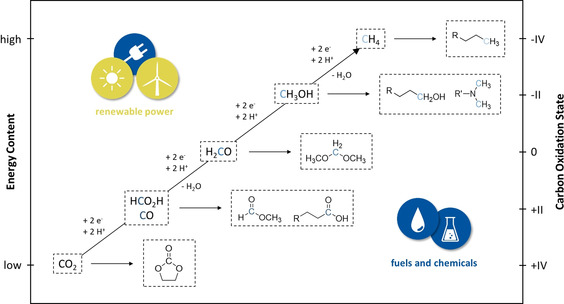
Schematic correlation between energy content and carbon oxidation state of CO2‐based C1 compounds as well as possible higher molecular products thereof.
Organometallic catalysis using molecular hydrogen obtained from water electrolysis or other C‐free technologies [34] as the reducing agent has recently known a very dynamic development to map out the molecular landscape shown in Figure 3. The level of reduction could be expanded beyond the formate stage. This led to the development of novel synthetic pathways to acids, esters, aldehydes, alcohols, and methylation reactions. [35] While synthetic methods for the introduction of CO2 into molecular diversity using dihydrogen are thus becoming increasingly available,[ 35c , 36 ] electrocatalysis is still mainly focused on the production of C1 products.
It is, however, well conceivable that suitable metal catalysts transfer electrons from the electrode material to CO2, while protons or other suitable electrophiles compensate for the charge balance. [37] Such electrocatalytic processes provide alternative reduction methods, eliminating the extra step of electrochemical hydrogen generation via water electrolysis (cf. challenge 2). They also offer the potential to operate at milder conditions, obviating high temperatures and pressures often necessary for CO2 hydrogenation. Furthermore, and maybe most intriguingly, different elementary steps in the molecular mechanisms for CO2 activation by decoupling electron transfer and bond formation can open novel pathways to devise synthetically useful transformations (cf. challenge 3).
With the present review, we hope to unlock further the potential of electrocatalytic CO2 conversion by taking an organometallic point of view of the underlying molecular principles. We attempt to categorize the mechanisms for metal‐complex‐catalyzed electrochemical CO2 reduction from this perspective and discuss the possible extension of these concepts towards possibilities to generate molecular complexity exploiting the synergy of the two fields.
2. Mechanisms in Electrochemical CO2 Reduction Catalyzed by Transition Metal Complexes
2.1. General Considerations
The high energy barrier for conventional electrochemical CO2 activation is generally associated with the high energy demand to force the linear neutral molecule into the bent radical anion, resulting in a high overpotential requirement for the one‐electron reduction of CO2 to CO2 .− (at −1.97 V vs. normal hydrogen electrode, NHE, in N,N‐dimethylformamide, DMF). The overpotential also reflects a variety of interfacial phenomena, including mass transfer, charge transfer, and others. By using transition metal catalysts, however, the critical potential needed for the reaction is often no longer given by the onset potential of the CO2 reduction, E onset, which includes the overpotential, [38] but by the reduction potential of the catalyst, E cat. To generate a sufficiently strong reductant and yield a satisfying conversion, the least negative limit for the required potential is set by the thermodynamic potential of the CO2 reduction, E thermo (Figure 4). [39]
Figure 4.
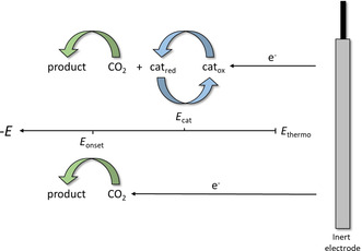
Relative positions of defining potentials for purely electrochemical and electrochemical transition metal catalyzed activation of CO2 as well as the proposed way of electron transfer.
For the two most frequently targeted carbon dioxide reduction products, carbon monoxide and formate, the reduction channels of CO2 to either CO [−0.106 V vs. standard hydrogen electrode, SHE, Eq. 1] or HCO2H [−0.250 V vs. SHE when pH > pK a, Eq. 2] are thermodynamically both accessible under the typically applied potentials. [40] Therefore, the selectivity towards these products can be determined largely through kinetic differentiation of the catalytic pathways and hence by molecular catalyst design.
| (1) |
| (2) |
The mechanisms impacting the first electron transfer (electrode→oxidized catalyst species, catox) are largely dependent on interfacial parameters such as electrode composition, surface structure, conductivity of the electrode and solution, composition of the electrical double layer, etc.[ 38a , 41 ] While this part of the catalytic process is also of great importance for the overall efficiency, we will concentrate on the electron transfer from the reduced catalyst species, catred, to the CO2 molecule and the bond‐making and ‐breaking steps initiated thereby. Ultimately, these elementary processes are controlled by the electronic and geometrical framework at the metal center as defined by the ligand environment and hence are closely related to the traditional realm of organometallic catalysis. Before discussing these control mechanisms, we first need to clarify the use of the expressions outer‐sphere and inner‐sphere mechanisms in electrocatalysis and organometallic catalysis.
In electrocatalysis, the outer‐sphere pathway, also described as redox catalysis, refers to a pathway in which the catalyst system only behaves as an electron carrier from the electrode to carbon dioxide. [42] In this case, the ligand environment is not substantially involved, and the electronic interaction between both reaction partners is marginal. [43] Therefore, the electron needs to bridge a certain spatial dimension. Since the main intermediate species for further reactions of CO2 is the CO2 .− radical anion, the reaction pathways are comparable to those described by Costentin et al. for the reduction of CO2 directly at the electrode surface (Scheme 1). [44]
Scheme 1.
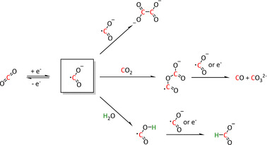
Typical reaction pathways initiated through an outer‐sphere one‐electron transfer for CO2 activation. [44]
The radical anion can either dimerize to the oxalate species or give CO and carbonate by reaction with a further equivalent of CO2 because of its amphoteric character. In the presence of water, the formate anion is formed. [44] This type of electron transfer is favored over the direct transfer at the electrode because of the higher electron availability which, in turn, is caused by the allocation of the catalyst in between the substrate molecules. Furthermore, the activation can be accelerated by a shift of the equilibrium if the subsequent reactions are thermodynamically favored and rapid (e.g., protonation or radical coupling). [39]
In contrast to the outer‐sphere pathway, the inner‐sphere mechanism traverses a chemically bound carbon dioxide adduct at which the electron transfer occurs. Subsequently, the activation barriers for the reaction must be overcome to yield the desired product. Compared to the outer‐sphere mechanism as defined above, where the formation of the radical anion is unfavorable due to the high energy required to bend the linear CO2 molecule, the inner‐sphere catalytic conversion of CO2 takes advantage of its coordination to the transition metal. [45]
In organometallic chemistry, however, the distinction between inner‐ and outer‐sphere mechanisms is made according to the coordination of the substrate that is attacked by a reactive group already bound at the metal center. Considering the electron as the reactive group, all electrocatalytic reactions involving electron transfer to a metal‐bound CO2 fall into the inner‐sphere category. However, a second equally important pathway for CO2 reduction involves the formation of a metal hydride complex as an intermediate rather than direct electron transfer. While the hydride transfer may involve additional precoordination of CO2 and hence an inner‐sphere pathway, this is by no means required. [46] In fact, the hydride transfer to C=O units is the classic case for outer‐sphere reaction steps in organometallic catalysis, as prominently featured, for example, in the Noyori mechanism for the asymmetric hydrogenation of ketones. [47] These reactions formally involve the transfer of a hydride and a proton to the non‐coordinated substrate, either stepwise or in a concerted fashion through a five‐ or six‐membered transition state. The corresponding outer‐sphere H‐transfer from transition metal centers to CO2 is widely inferred in organometallic catalysis for CO2 hydrogenation. [35c]
Fortunately, the two disciplines share a common view of the molecular processes on the basis of the involved intermediates for which we propose a commonly applicable terminology. In essence, the reduced catalyst species [LmM]n−1 (M=metal, L=ligand, m=stoichiometry of coordinated ligands, n=formal oxidation state/charge of the metal) can transfer electrons to carbon dioxide via two distinct mechanisms (Scheme 2):
Scheme 2.
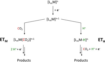
Categorization of the ETM and ETH pathways for electron transfer to CO2 during transition metal catalyzed electroconversion of carbon dioxide (M=metal, L=ligand, LA=Lewis acid, m=stoichiometry of coordinated ligands, n=formal oxidation state/charge of the metal).
-
electron transfer through the molecular complex, ETM
The electron is transferred to CO2 directly from the [LmM]n−1 unit, mostly—but not exclusively—by coordination of CO2 at the metal center.
-
electron transfer through the hydride, ETH
The electron is transferred to CO2 by hydride addition corresponding to a CO2 insertion into the M−H bond via an inner‐ or outer‐sphere mechanism.
The archetypical ETM and ETH pathways, as well as common variations thereof, will be explained conceptually in the next sections. Specific examples will be presented in the literature review in Section 3, followed by an attempt to extend the concept to more complex reaction schemes involving additional substrates beyond CO2 and protons in Section 4.
2.2. Electron Transfer through the Molecular Complex (ETM)
The coordination of CO2 to the transition metal center constitutes an essential prerequisite for the ETM pathway (Scheme 3). [48] It should be noted, however, that the electron transfer to CO2 in the ETM route occurs by the involvement of the entire molecular architecture comprising the transition metal and its ligand environment. A significant number of the transition metal complexes in electrochemical CO2 reduction rely on molecular architectures incorporating so‐called non‐innocent ligands (e.g., pyridines (py) or imines). Their ability to undergo redox reactions by accepting or donating electrons makes them additional electron carriers and a crucial part of the reduction cycle. [49] As an example, the CO2 reduction catalyst [Re(bpy)(CO)3]+ (bpy=2,2′‐bipyridine) investigated by Lehn and co‐workers [26] must be reduced twice to generate the active [Re(bpy)(CO)3]− species. In their work, Benson et al. demonstrated a formal reduction of the rhenium center in [Re(bpy)(CO)3]+ to the oxidation state zero and that the π* orbital of the bpy unit takes on the second electron. [50] Similar redox properties of organic compounds capable of CO2 reduction form the basis of metal‐free organocatalysts in electrocatalysis as described elsewhere. [51]
Scheme 3.
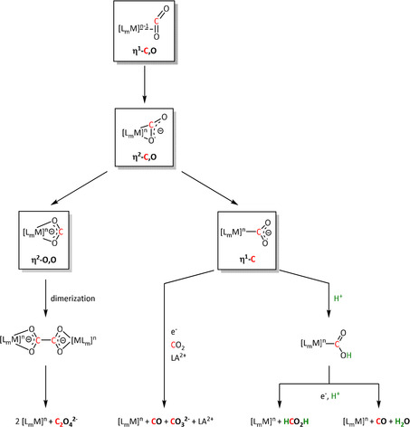
Coordination modes of CO2, resulting reaction pathways, and possible products of the ETM route (for definitions, see Scheme 2; LA=Lewis acid).
More than ten coordination modes of CO2 at up to four metal centers simultaneously in various oxidation states are reported in the literature.[ 16a , 46 , 52 ] For clarity, we discuss the mechanistic principles for the interaction with a single metal center only. The side‐on η2‐C,O bonding mode of neutral CO2 can lead to stable complexes, such as the famous Aresta complex, [53] and is widely inferred in thermocatalytic CO2 conversion, especially for [2+2] cycloaddition‐type transformations. The backbonding into the π* orbital, according to the Dewar–Chatt–Duncanson model, already leads to a bending of CO2, potentially activating it towards the full electron transfer. [54] This can result in two different coordination modes of the formal radical anion—η2‐O,O or η1‐C—defining a mechanistic junction for the formation of C1 or C2 products (Scheme 3). It is important to note, however, that the side‐on complexation does not necessarily form an intermediate, but is assumed often to be a transition state on the way to the other binding modes.
In the case of an η2‐O,O‐bound CO2 radical anion (Scheme 3, left), the carbon atom can be attacked by a second equivalent of the adduct to form a covalent bond. Dissociation of the two metal complexes leads to oxalate release, often followed by precipitation with cations in the solution, resulting in a shift of the equilibrium. Recent mechanistic [55] and theoretical investigations [56] on transition metal mediated oxalate formation (i.e., C−C coupling reaction) suggest a bimetallic intermediate featuring a μ‐η2:η1‐CO2 sandwich complex. This implies CO2 2− as an activated species, which has been found as a local minimum on the potential energy surface of many CO2 reactions. [56] It can react directly with an uncoordinated molecule of CO2[ 56 , 57 ] rather than involving an electrochemically generated CO2 radical anion. [58]
The η1‐C coordination corresponds to the crucial intermediate in most ETM reactions described to date. The metallacarboxylate intermediate can be protonated to the resulting hydroxycarbonyl species, which constitutes a second mechanistic junction. On the one hand, the release of water and carbon monoxide can be initiated, while, on the other hand, the addition of a second proton and reductive elimination releases formic acid. Isomerization of the hydroxycarbonyl intermediate to the formate species prior to the release of formic acid has been reported by Chen et al. (see Section 3.3, Scheme 16). [59]
Scheme 16.
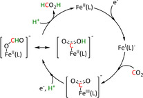
Reaction mechanism of the reduction of CO2 to HCO2H for pentadentate iron complexes proposed by Chen et al. Adapted with permission from ref. [59]. Copyright 2015 American Chemical Society.
The release of CO is generally accepted to be favored via a push–pull mechanism. The reduced metal center donates electron density to the carbon atom through the η1‐C coordination, which thus occupies the antibonding orbitals. In the presence of Brønsted acids (HA, Scheme 4), two equivalents of acid can interact with the anionic oxygen atom to reduce its electron density. The two factors together lead to a significant weakening of the C−O bond, eventually resulting in the elimination of water. Further uptake of an electron leads to CO release and catalyst recovery.[ 39 , 60 ] It was found that the acid used may be neither too strong nor too concentrated to keep the concentration of protons near the electrode low and avoid direct proton reduction to molecular hydrogen as a frequent side reaction. Methanol, 2,2,2‐trifluoroethanol (TFE), phenol, and even water are suitable weak acids.[ 60a , 61 ] Since the influence of proton donors is crucial for the catalytic performance, several attempts have been reported to incorporate carboxylic acid or phenol groups in the ligand systems as proton sources or relays. [62]
Scheme 4.
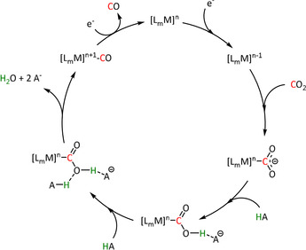
General push–pull mechanism of the Brønsted acid (HA) assisted reduction of CO2 to CO.
Although the overall reaction to convert carbon dioxide into carbon monoxide and water consumes two protons and two electrons in each case, the sequence of reduction and protonation (reduction first vs. protonation first) has a significant effect on the required potential and, hence, the energy efficiency of the reaction. In general, reduction first occurs at more negative potentials and, therefore, is the less desired pathway. The competition between “protonation first” and “reduction first” pathways was explicitly observed for Mn‐ and Re‐bpy complexes by Riplinger et al. (Scheme 5).[ 60a , 63 ] According to their arguments, protonation of the CO2 adduct is necessary to stabilize the metallacarboxylate for manganese, since CO2 binding alone is endergonic relative to the dimerization of the pentacoordinated intermediate (see Section 3.2). Rhenium, however, exhibits a higher binding affinity for a sixth ligand compared to its 3d analogue. This results in a need for more negative potentials to generate the pentacoordinated active species and thus favors the “reduction first” pathway. Conversely, Mn needs less high overpotentials and, therefore, can traverse both routes.
Scheme 5.
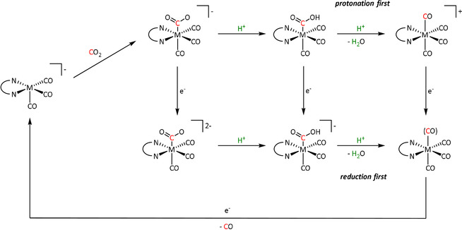
“Protonation first” and “reduction first” mechanisms described by Riplinger et al. (M=Mn/Re, N∩N=bpy). Adapted with permission from ref. [60a]. Copyright 2015 American Chemical Society.
The possibility of a different reaction channel has been suggested in the presence of alkaline‐earth Lewis acids (LAs; Scheme 3, middle). The LA stabilizes the intermediate η1‐CO2 − species, allowing a second equivalent of CO2 to take part in the reaction. Through a proposed cyclic transition state, one oxygen from CO2 is transferred formally as O2− to yield reduced CO and carbonate, which is released as the LA salt. Sampson et al. postulated this pathway for electrocatalytic CO formation using Mn‐bpy complexes (see Section 3.2). [64]
2.3. Electron Transfer through the Hydride (ETH)
In the ETH route, a metal hydride (M‐H) complex acts as the reactive intermediate, which is formed from the electron‐enriched, reduced metal center and a proton. Hydride attack at the electrophilic carbon center of CO2 transfers the reduction equivalents simultaneously with the bond formation. The elementary processes are very similar and, in many cases, even identical to the analogous steps in the thermocatalytic transition metal‐catalyzed hydrogenation of CO2 to provide C1 molecules such as formic acid and methanol (Scheme 6). There are numerous examples of catalysts, and the intricate details of the mechanisms have been studied widely in this area of CO2 conversion.[ 36b , 65 ]
Scheme 6.
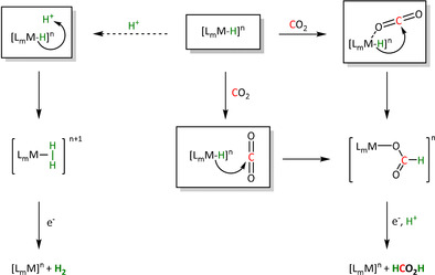
Reaction pathways and possible products of the ETH route (for definitions see Scheme 2).
In cases where the bond formation occurs via migratory insertion, end‐on η1‐O coordination of the CO2 typically precedes the hydride transfer. Although the side‐on η2‐C,O coordination is also possible, it is less likely as intermediate because the electrophilicity of the carbon center is lower in this binding mode. The η1‐O coordination corresponds to a Lewis acid/base interaction with the free lone pair of the CO2 molecule. Given the typically highly reduced state of the metal center, its Lewis acidity is rather weak in many cases, however. The hydride transfer through direct outer‐sphere attack at CO2 is, therefore, a viable alternative in such systems. In both cases, a formate complex will be formed after the hydride transfer, whereby the carboxylate group may be coordinated in either a monodentate or bidentate fashion. Only the monodentate mode is shown in Scheme 6 for clarity.
Subsequently, the formate ligand can be protonated, followed by dissociation of formic acid. The protonation usually occurs at the non‐coordinated C=O bond in the monodentate form. However, protonation can also occur already at the stage of the hydride complex, resulting in the evolution of molecular hydrogen as an important side reaction. The pH of the reaction medium is, therefore, an important extrinsic parameter for selectivity control. [66]
Although transition metal hydride intermediates strongly favor the formation of formate products, CO can be evolved in certain cases. Isomerization of the metal formate intermediate to the hydroxycarbonyl species of the ETM pathway has been reported to account for CO formation, for example, with ruthenium catalysts (vide infra in Scheme 20 in Section 3.3). [67] For rhodium phosphine complexes, the distinct pathways to formate and CO via the hydride and hydroxycarbonyl intermediates, respectively, have been initiated by electro‐ and thermochemical means within the same ligand framework. [68]
Scheme 20.

Isomerization mechanism for CO production via crossing of the ETH‐formed formate intermediate to the hydroxycarbonyl intermediate of the ETM pathway proposed by Machan et al. Adapted with permission from ref. [67]. Copyright 2015 American Chemical Society.
3. Transition Metal Complexes as Catalysts in Electrochemical CO2 Reduction
The following sections provide an overview of the state of the art for CO2 conversion into valuable products combining transition metal catalysts and electrochemistry. The vast majority of the known catalytic systems aim at the production of CO or formate or mixtures thereof. From the organometallic perspective, the material is organized according to the position of the metal component in the periodic table. Due to the rapidly growing number of examples and the intertwining of several fields such as photo‐, thermo‐, and electrocatalysis, the selection is not claimed to be exhaustive. Besides general indicators such as turnover numbers (TONs) and turnover frequencies (TOFs), the overpotential η, the Tafel plot (i.e., log(TOF) vs. overpotential), and the Faradaic efficiency (FE, i.e., percentage of electrons used to generate a specific product) are commonly reported. [69] Here, we will focus on the Faradaic efficiency as a proxy for the yield of a specific product in an electrochemical reaction. H2 and CO as products are not included for Faradaic yields below 10 %. Wherever possible, the data will be corroborated with the reaction mechanisms, as defined in the previous section. Cyclic voltammetry (CV) is discussed in more detail when it constitutes the core method for the mechanistic analysis of specific systems. Studies investigating the CO2 binding mode explicitly are also highlighted. Since the evaluation of the performance of an electrocatalytic system is strongly dependent on reaction conditions (e.g., reference electrodes/couples, electrolyte, CO2 saturation, proton source [69d] ), conclusions about intrinsic structure–activity relationships have to be drawn with great care. A similar caveat applies to the mechanistic interpretation, where extrinsic parameters may also influence the preferred pathway.
3.1. Group 6: Cr, Mo, W
Group 6 of the periodic table comprises several examples of metal complexes that show activity in the electrochemical reduction of CO2. Nature uses molybdenum and tungsten as the active center in enzymes for reversible interconversion of CO2 and formate, which is undoubtedly a source of inspiration. [70] As summarized in Table 1, the major products obtained by Group 6 metals are carbon monoxide, with maximum Faradaic efficiencies in the range of 100 % and, to a limited extent, formate as well (Table 1, entries 2a and 3; note: all tables can be found in the appendix after the main text). The most frequently reported ligands for the production of CO are combinations of carbonyls and bpy derivatives.[ 49c , 71 ] By using complementary spectroscopic and electroanalytical methods (CV, chronoamperometry, and UV/Vis as well as IR spectroscopy), Tory et al. could identify the [M(CO)3(bpy)]2− species (M=Cr, Mo, W) as catalytically active at potentials below −2.0 V vs. ferrocene/ferrocenium (Fc/Fc+). [71b] Similar to the rhenium complexes reported by Lehn and discussed in Section 3.2, the bpy unit serves as an electron‐acceptor functionality and, thus, constitutes a crucial part of the catalyst. This might be at least partly the reason for the preferential generation of CO regardless of the central atom (i.e., Cr, Mo, or W).
Table 1.
Catalytic systems, major products, maximum FEs, and mechanisms of Group 6 transition metal complexes in electrochemical CO2 reduction (n.a.=not available, prop.=proposal, comp.=computational investigation, exp.=experimental evidence).
|
Entry |
Cat. system |
Substitution |
Major product |
Max. FE (%) |
Mechanism |
Basis |
Method |
Ref. |
|---|---|---|---|---|---|---|---|---|
|
1a |
[Cr(CO)4(bpy)] |
– |
CO/H2O |
n.a. |
ETM |
exp. |
IR‐, UV/Vis‐SEC |
|
|
1b |
|
– |
CO/H2O |
96±8 |
ETM |
prop. |
n.a. |
|
|
2a |
[Mo(CO)4(L)2] |
L=CO L∩L=4,4’‐di‐R‐bpy R=H, Me, tBu |
CO/CO3 2− CO/H2O HCO2 − |
95 [49c] n.a. n.a. |
No H+: ETM (CO) H+: ETH (HCO2 −) |
exp. [49c] |
IR‐, UV/Vis‐SEC, VSFG |
[49c, 71, 72c] |
|
2b |
|
R=Ph, 2,6‐(iPr)2C6H3 |
n.a. |
n.a. |
ETM |
exp. comp. |
IR‐SEC, NMR, XRD DFT |
|
|
3 |
|
N∩N=di‐R‐bpy, bis(2,6‐dimethyl‐ phenyl)acenaphthene‐ quinonediimine R=H, Me |
CO/H2O HCO2 − |
n.a. |
ETM (CO) ETH (HCO2 −) [73] |
exp. [72b] comp. [72b] |
IR‐SEC DFT |
|
|
|
|
|
|
|
|
|
|
|
|
4 |
[W(CO)4(L)2] |
L=CO L∩L=2,2′‐dipyridylamine, 4,4’‐di‐R‐bpy, 4,6‐diphenyl‐2,2′‐bpy, 6‐(2,6‐dimethoxyphenyl)‐ 4‐phenyl‐2,2′‐bpy R=H, tBu |
CO/CO3 2− CO/H2O |
n.a. 109±7 [71a] |
ETM |
exp. comp. [76] |
IR‐, UV/Vis‐SEC DFT |
[49c, 71, 76, 77] |
Several recent papers emphasize the enhanced CO dissociation rate on gold electrodes, which shifts the mechanism towards “CO loss first” at a potential significantly less negative than that for “reduction first” (Scheme 7). [72] This effect even surpasses the influence of structural changes in the ligand environment. [72c]
Scheme 7.
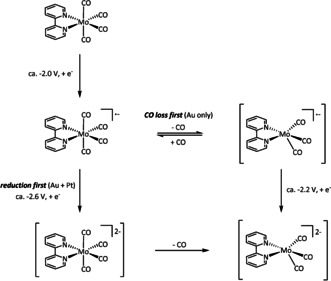
Mechanistic shift towards the active species [Mo(CO)3(bpy)]2− and enhanced CO dissociation rates by usage of gold electrodes as proposed by Neri et al. [72a]
The hexacarbonyl derivatives of the bipyridine catalysts (Table 1, entries 2a and 4) were investigated by Grice et al. to determine whether Group 6 metal complexes could convert CO2 even without the additional redox activity of the non‐innocent bpy ligand. The investigated complexes still showed catalytic performance, but an unexpected behavior was observed in the presence of water. In the absence of H2O, a catalytic current for reaction with CO2 of approximately −380 μA was obtained. Upon the addition of water, this current decreased to only −50 μA. Following the proposed reaction pathways for CO2 reduction described above (Scheme 4), water seems to act as a proton source that opens a second route to the product besides the disproportionation of two CO2 equivalents. Alternatively, Grice et al. proposed that water could coordinate to the metal instead of the CO2 molecule. [49c]
Besides the influence of protons on the mechanism for CO evolution, the authors also described a switch to the ETH pathway resulting in formate as the product, since the formation of the crucial hydride species is enabled when a hydrogen source is present (Scheme 8).
Scheme 8.
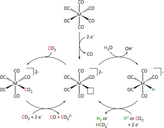
Potential catalytic cycles for electrocatalytic CO2 reduction by Group 6 M(CO)6 species in the presence and absence of a proton source as proposed by Grice et al. Reprinted with permission from ref. [49c]. Copyright 2016 American Chemical Society.
The only other example for formate generation of Group 6 transition metals was reported for a [Mo(CO)2(η3‐allyl)(bpy)(NCS)] complex (Table 1, entry 3). Tory et al. applied the same analytical methods as those used for the bpy/carbonyl complexes and showed that the reaction mechanism involves a Mo dimer after dissociation of the NCS− anion. Furthermore, they were able to detect the presence of formate in solution as well as coordinated to the metal in the [Mo(CO)2(η3‐allyl)(bpy)(O2CH)] complex by IR analysis, indicating an ETH reaction pathway. [73]
The Kubiak group published one of the few examples of Group 6 transition metal complexes that do not involve a bipyridine backbone. [75] They proposed that the pyridyl monoimine (PMI) ligand coordinating the molybdenum center (Table 1, entry 2b) can be reduced in the process. Upon reaction with CO2, it generates a partly stable CO2 adduct as depicted in Figure 5 rather than converting it.
Figure 5.

[(iPr2PhPMI)Mo(CO)3(CO2)]2− adduct reported by Kubiak and co‐workers. [75]
Their proposal was supported by 2D NMR spectroscopy, as well as spectroelectrochemical (SEC) and X‐ray crystallographic analysis. Furthermore, the authors reported that the detected FE of 10 % for CO originates from ligand dissociation rather than catalytic activity. This work further substantiates the possible involvement of the ligand in the coordination of CO2 for Group 6 transition metals.
3.2. Group 7: Mn, Re
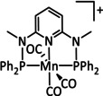
The bipyridine ligand class, in combination with carbonyl ligands, also plays an important role in Group 7 transition metal‐based catalysts. [78] Methyl, [79] tert‐butyl, [80] and mesityl groups [81] as well as amide functionalities [82] constitute only a selection of modifications that were used to change the coordination environment of the metal (Table 2, entries 1a–i; Table 3, entries 1a–i). Furthermore, ligand platforms based on (P)NP pincers [83] (Table 2, entries 2a and 2b), N‐heterocyclic carbenes [84] (Table 2, entries 3, 9, and 11; Table 3, entry 3a), and various other nitrogen‐containing aryl compounds (e.g., based on terpyridine (tpy), phenanthroline (phen), triazol (tr), and phthalocyanine (Pc)) were reported in the literature. [85] Both manganese and rhenium compounds yield selectively carbon monoxide with Faradaic efficiencies above 90 % (Table 2 and Table 3).
Table 2.
Catalytic systems, major products, maximum FEs, and mechanisms of Mn complexes in electrochemical CO2 reduction (n.a.=not available, prop.=proposal, comp.=computational investigation, exp.=experimental evidence).
|
Entry |
Cat. system |
Substitution |
Major product |
Max. FE (%) |
Mechanism |
Basis |
Method |
Ref. |
|---|---|---|---|---|---|---|---|---|
|
1a |
|
n=0, 1 X=CN, CO, MeCN Y=CH, N |
CO/H2O |
98 [89] |
ETM |
exp. comp. |
[86, 88–91] |
|
|
1b |
|
n=0, 1 R=H, Me, Et, tBu, Ph, Bn, CN, CO2H, CO2C3H6C4H5N, CF3, NMe2, OH, OMe, SMe X=MeCN, Br |
CO/H2O H2 |
100±15 [80] 45 [92] |
ETM |
exp. comp. |
DFT [93] |
[79–80, 92–94] |
|
1c |
|
R1=H, OMe, Br R2=C2H4OH |
n.a. |
n.a. |
ETM |
exp. comp. |
IR, NMR DFT |
|
|
1d |
|
– |
CO/H2O HCO2H H2 |
34±4 8±2 59±8 |
low c cat: ETH high c cat: ETM |
exp. |
IR‐, UV/Vis‐SEC |
|
|
1e |
|
R=C6H4NH2, SMe |
CO/H2O |
100±5 [94a] |
ETM |
prop. [97] |
n.a. |
[94a, 97, 98] |
|
1f |
|
R1=H, Ph R2=H, CH2NEt2, OH, OMe R3=H, OH, F |
CO HCO2H |
90 [99] 63 [100] |
no H+: ETM H+: ETH ETM |
NMR, IR‐SEC DFT |
[62a, 99–102] |
|
|
1g |
|
n=0, 1 R1=H, Me, Et, CH2NHEt, CH2NEt2, CH2‐morpholine, CH2OH, CHO, CO2H, NH2, OH,OMe, F R2=H, Me, CH2NEt2, OH X=MeCN, OTf, Br |
CO/CO3 2−[64, 103] CO/H2O [103] HCO2H |
98±3 [64] n.a. 90 [100] |
ETM ETH |
exp. exp. [100] comp. [100] |
IR‐SEC, [64] (PR‐) TRIR [104] DFT IR‐SEC, NMR DFT |
[64, 81, 100, 103, 104] |
|
1h |
|
R1=H, Me R2=Me, tBu |
CO/H2O |
78 |
ETM |
comp. |
DFT |
|
|
1i |
|
– |
CO/H2O |
98 |
ETM |
comp. |
DFT |
|
|
2a |
|
– |
CO/CO3 2− |
96 |
n.a. |
n.a. |
n.a. |
|
|
2b |
|
– |
CO/CO3 2− H2 |
96 (CO+H2) |
n.a. |
n.a. |
n.a. |
|
|
3 |
|
R1=Me, Et R2=H, C6H4OH X=CN, SCN, Br, I Y=CH, N |
CO/H2O H2 |
73 [106] 53 [107] |
ETM |
DFT |
[106–108, 109] |
|
|
4 |
|
R1=H, Me R2=H, iPr, tBu R3=H, iPr |
CO/CO3 2− |
60 |
ETM |
exp. comp. |
IR‐, UV/Vis‐SEC DFT |
|
|
5 |
|
– |
CO/H2O |
n.a. |
ETM |
exp. |
IR‐, UV/Vis‐SEC |
|
|
6 |
|
Ar=CN(2,6‐(2,6‐(iPr)2C6H3)2C6H3) n=0, 1 X=THF, Cl, Br, I |
CO/CO3 2− |
n.a. |
ETM |
exp. |
IR‐SEC |
|
|
7 |
|
– |
CO/H2O |
129[a] |
n.a. |
n.a. |
n.a. |
|
|
8a |
|
n=0, 1 X=MeCN, Br |
CO/H2O |
100 |
ETM |
exp. |
EPR, IR‐, UV/Vis‐SEC |
|
|
8b |
|
n=0, 1 R=H, Me, C6H4CH2NEt2 X=MeCN, Br |
CO/H2O HCO2H |
62 [91] 70 [100] |
ETM (CO) ETH (HCO2H) |
exp. |
NMR, IR‐SEC [100] DFT |
[91, 94c, 100] |
|
9 |
|
R=Me, Mes |
CO/CO3 2− CO/H2O |
95 [114] 98 [109b] |
ETM |
exp. [109b] comp. [109b] |
IR‐, [114] UV/Vis‐SEC DFT |
|
|
10 |
|
– |
CO/H2O |
88 |
ETM |
exp. comp. |
EPR‐, IR‐SEC, PR‐TRIR DFT |
|
|
11 |
|
R=Me, Bn |
CO/CO3 2− CO/H2O |
93 [116] 87±3 [117] |
ETM |
DFT |
||
|
12 |
|
R=C6F4‐S‐(PEG7)‐OMe |
CH3OH CH3CO2 − |
23 63 |
ETM |
exp. comp. |
EAS,[b] GC‐MS, IL, IR‐, UV/Vis‐SEC, NMR DFT |
|
|
13 |
|
– |
HCO2 − H2 |
26 77 |
n.a. |
n.a. |
n.a. |
[a] Likely caused by loss of carbonyl ligand. [b] Electronic absorption spectroscopy.
Table 3.
Catalytic systems, major products, maximum FEs, and mechanisms of Re complexes in electrochemical CO2 reduction (n.a.=not available, prop.=proposal, comp.=computational investigation, exp.=experimental evidence).
|
Entry |
Cat. system |
Substitution |
Major product |
Max. FE (%) |
Mechanism |
Basis |
Method |
Ref. |
|---|---|---|---|---|---|---|---|---|
|
1a |
|
n=0, 1 X=H, MeCN, CO, HCO2, HCO3, CH3C(O), OMe, THF, OTf, PPh3, P(OEt)3, Cl, Br |
CO/CO3 2− CO/H2O HCO2 − H2 |
98 [123] n.a. [125] 74 [126] |
ETM |
exp. |
EPR, [128] IR‐SEC,[ 125 , 129 ] Raman [130] DFT |
[26, 60a, 63, 122–131] |
|
|
|
|
|
|
|
|
|
|
|
1b |
|
R=vinyl, ethynyl, C6H4NH2, norbornenyl derivatives, CH2NHCOCH3/peptide resins, 4‐piperidinyl‐1,8‐naphthalimide, NHCSNH‐C6H4CF3, SMe, thiophene, 2,2′:5′,2′′‐terthiophene, 3′‐ethynyl 2,2′:5′,2′′‐terthiophene |
CO/H2O |
100 [98] |
ETM |
exp. [132] |
IR‐SEC |
[94a, 98, 132, 133] |
|
|
|
|
|
|
|
|
|
|
|
1c |
|
n=0, 1 R=Me, tBu, bisphenylethynyl, CH2NHCOCH3, tyrosyl derivative, CH2NEt2, CH2OH, CN, CO2H, CF3, NH2, NHMe, NMe2, OH, OMe, Si(Ph)4 X=H2O, Cl |
CO/CO3 2−[134] CO/H2O HCO2H |
100 [94f] 71 [135] 12 [136] |
ETM |
exp. comp. [130] |
EPR, [130] IR‐SEC, [87a] Raman [130] DFT |
[82, 94f, 130, 133a, 134–137] |
|
1d |
|
R1=H, C2H3 R2=Me, NHMe, NMe2, CF3 |
CO/CO3 2− CO/H2O |
92 [138] 73 [94f] |
n.a. |
n.a. |
n.a. |
|
|
1e |
|
X=O, S |
CO/CO3 2‐ |
90 |
n.a. |
n.a. |
n.a. |
|
|
1f |
|
– |
CO/H2O |
89 |
ETM |
exp. comp. |
IR, UV/Vis‐SEC DFT |
|
|
1g |
|
R=C2H4OH |
CO HCO2H |
95 [141] 27 [141] |
ETM (CO) ETH (HCO2H) |
exp. comp. |
DFT [95] |
|
|
1h |
|
R1=Ph, C6H4OH R2=Ph, phenyl‐2,6‐ diol, phenyl‐3,4,5‐triol |
CO/CO3 2− |
100 |
ETM |
prop. |
n.a. |
|
|
1i |
|
R=H, Me |
CO |
73 |
ETM |
prop. |
n.a. |
|
|
2a |
|
R1=H, NH2, 4‐piperidinyl‐ 1,8‐naphthalimide R2=H, NH2 R1∩R2=nanographene |
CO/H2O |
96 [144] |
ETM |
comp. [145] |
DFT |
|
|
2b |
|
R=H, Me, Mes, 4‐MeOC6H4, 2,6‐(MeO)2C6H3, 3,5‐(MeO)2C6H3, 2,4,6‐(MeO)3C6H2, 3,4,5‐(MeO)3C6H2 |
CO/H2O |
84 [146] |
ETM |
prop. |
n.a. |
|
|
2c |
|
– |
CO/CO3 2− |
n.a. |
ETM |
prop. |
n.a. |
|
|
2d |
|
R=H, tBu, CF3, NO2 |
CO |
53 |
n.a. |
n.a. |
n.a. |
|
|
3a |
|
R1=Me, p‐C6H4R2, (m‐CF3)2C6H3 R2=CN, CF3, NO2 X=Cl, Br Y=CH, N |
CO/H2O |
92 [84] |
ETM |
prop. [84] |
n.a. |
|
|
3b |
|
R1=tBu, pyrenyl R2=H, Me Y1=C, N Y2=CH, NH |
CO/H2O |
85 [151] |
n.a. |
n.a. |
n.a. |
|
|
4a |
|
R1=C12H25, tolyl, C6H2(tBu)3, C3H6OH R2=H, NO2, OMe X=Cl, Br |
CO/H2O |
92 |
n.a. |
n.a. |
n.a. |
|
|
4b |
|
R=2,6‐(iPr)2C6H3, CH2C6H5, CH2C6F5 |
CO/H2O |
99 |
ETM |
exp. |
IR‐SEC |
|
|
5 |
|
R=H, Me, Ph |
CO/H2O |
61 |
ETM |
comp. |
DFT |
|
|
6a |
|
– |
n.a. |
n.a. |
n.a. |
n.a. |
n.a. |
|
|
6b |
|
R=H, Me |
CO |
105±5 |
n.a. |
n.a. |
n.a. |
|
|
7 |
|
L=pyrazole, 3,5‐dimethylpyrazole, indazole, 3‐(2‐pyridyl)pyrazole |
CO |
89 |
ETM |
prop |
n.a. |
|
|
8 |
|
L=CO, Cl L∩L=bpy, phen n=0, 1 R=H, Ph, tolyl,C6H4Br, C6H4‐[M] |
CO/H2O |
94 |
ETM |
prop. |
n.a. |
The most prominent [Mn(bpy)(CO)3]+ type complexes (Table 2, entries 1a–i) are known to dimerize to [Mn(bpy)(CO)3]2 after an initial one‐electron reduction concomitant with halide dissociation (if applicable). Further reduction leads to the formation of the active species [Mn(bpy)(CO)3]− as investigated by Kuo et al. [86] In a report by Bourrez et al., the corresponding reduction waves occur at −1.56 V and −1.80 V vs. Ag/Ag+ electrode. [79] Since dimer formation is reported to be relatively slow when compared to the redox processes, the overall reaction rate decreases. [62a] To prevent this behavior, Sampson et al. incorporated bulky mesitylene (Mes) moieties into the bpy unit. The corresponding complex showed a single two‐electron reduction wave at −1.6 V vs. Fc/Fc+. Controlled potential electrolysis (CPE) at −2.2 V vs. Fc/Fc+ with 0.3 M TFE as acid resulted in a Faradaic efficiency of 98±6 %. [81] Mechanistic investigations by Machan et al. using infrared spectroelectrochemical (IR‐SEC) analysis as well as vibration sum‐frequency generation (VSFG) spectroscopy by the Cowan group led to the identification of a carbon‐bound intermediate following the ETM pathway. [87] DFT calculations by Lam et al. are in agreement with this interpretation of the experimental observations. [88]
While usually Brønsted acids are employed to direct the push–pull mechanism of the ETM pathway towards CO and H2O (Scheme 4), Sampson et al. shifted the mechanism towards CO and CO3 2− formation by using alkaline‐earth metal cations (especially Mg2+) as Lewis acids (Table 2, entry 1g). [64] Hence, the cation stabilizes an M–CO2 − species, which enables the reaction of a second CO2 molecule (Scheme 9). The precipitating magnesium carbonate, in combination with the released CO gas, shifts the equilibrium even further to the product side compared to CO evolution alone. However, the deposition of MgCO3 at the electrode surface can inhibit the reaction in the long run. Complementarily to the experimental investigations, computational studies of Wang et al. support these mechanistic insights. [103]
Scheme 9.
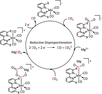
Lewis acid assisted electrocatalytic reduction of CO2 to CO and CO3 2− (R=mesityl). Adapted with permission from ref. [64]. Copyright 2016 American Chemical Society.
Apart from the carbonate dianion as the product of the reductive disproportionation of CO2, bicarbonate as its protonated form, can also act as an intermediate in the catalytic cycle. Zeng et al. described a catalyst system based on the 1,4‐diazabuta‐1,3‐diene ligand containing isopropyl substituents and performed extensive IR‐ and UV/Vis‐SEC measurements to elucidate the mechanism of the observed reduction of CO2 to CO. [110] During their investigations, they were able to identify an η1‐OCO2H− intermediate formed at ca. −1.4 V vs. Fc/Fc+ based on the assignment of the C‐O IR frequencies, and could even chemically confirm the identity of the active species. However, it turned out that a further unidentifiable intermediate generated at more negative potentials of 650 mV is ultimately responsible for the release of CO. The authors do not provide a Faradaic efficiency for the reaction but propose that the elevated concentration of CO near the electrode surface enables the formation of a dormant [Mn(CO)5]+ species that limits the overall effectivity of the system.
Koizumi et al. used deprotonated triethanolamine as a monodentate ligand on their Mn–bpy complexes to capture carbon dioxide. [95] The reversible insertion of CO2 into the Mn−O bond according to the proposed mechanism (Scheme 10) occurred with an equilibrium constant >1000 and was confirmed by NMR and IR spectroscopy as well as DFT calculations. However, the conversion of the coordinated substrate was not addressed in this report.
Scheme 10.

Possible mechanism of CO2 insertion into the Mn−O bond (R=CH2CH2OH). [95] Published by The Royal Society of Chemistry.
A similar system using rhenium instead of manganese showed that M–CO2 binding and transformation occurs even for gas mixtures with low CO2 concentrations such as air (vide infra).
Going further into the topic of ligand‐assisted CO2 capture, the Chardon‐Noblat group investigated N,N′‐coordinated 1,10‐phenanthroline‐5,6‐dione manganese complexes. They showed that the keto groups play a crucial role in electrochemical CO2 conversion (Table 2, entry 8a). [113] According to the authors, each functionality can undergo one‐electron reduction to the radical anion followed by the formation of the carbonic acid adduct (Scheme 11).
Scheme 11.
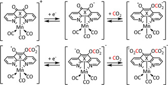
Two‐electron reduction of Mn(phen‐dione) in the presence of CO2 (X=MeCN). [113]
Despite a Faradaic efficiency of 100 % for the conversion of CO2 to CO at −1.70 V vs. Ag/Ag+, the authors could not directly correlate the catalytic activity to the interaction of CO2 with the reduced ligand system.
A well‐known strategy to increase the activity of a homogeneous electrocatalyst is its direct immobilization on the electrode surface. [349] This facilitates electron transfer from the electrode to the metal center. Sun et al. formed covalent bonds between their NH2‐group‐containing ligand systems and the carbon‐based working electrode by 1) electrooxidation of the amino functionality and surface carbon to form C−N bonds and 2) electroreduction of the corresponding diazonium salts to form C−C bonds (Table 2, entry 1e). [98] In both cases, the Faradaic efficiency for CO remained close to 100 %, while the TON increased from 7 for the homogeneous catalyst to more than 300 upon immobilization in only a quarter of the reaction time. The authors did not address possible changes in the reaction mechanism pathway that could constitute an alternative reason for enhanced productivity. Further studies on this topic and a general overview published by the same group can be found elsewhere in the literature.[ 97 , 121 ]
In the same context, a report by Reuillard et al. emphasizes the effect of the concentration of the catalyst attached to the electrode surface on the reaction mechanism (Scheme 12). The authors considered a pyrene (pyr)‐modified bpy‐based ligand system to exploit π–π stacking interactions between the ligand and the carbon electrode (Table 2, entry 1d). [96] As previously mentioned, most of the Mn–bpy catalysts for electrochemical CO2 reduction traverse a dimer state before generating the active species for CO formation. This, however, requires a sufficiently high catalyst concentration, which is confirmed by the formation of CO from CO2 in a Faradaic yield of ca. 34 % only at increased catalyst loadings as the dimerization becomes more favorable. When less catalyst is adsorbed at the electrode, the authors detected HCO2H (FE=8 %) accompanied by H2 generation with a maximum FE of 59 %. Mechanistic evaluation by UV/Vis‐ and IR‐SEC indicated a switch from the ETM pathway for CO generation to the ETH mechanism. These findings are in line with the catalytic results since HCO2H and H2 can both originate from an involved metal hydride species during the ETH catalytic cycle.
Scheme 12.
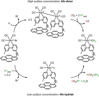
Schematic representation of [Mn(bpy‐pyr)(CO)3Br] immobilized on a carbon nanotube sidewall with mechanistic change due to variation of the catalyst loading. [96]
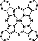
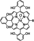
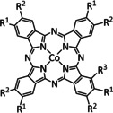
Other examples of Mn‐based molecular catalysts capable of formate formation during electrochemical CO2 reduction are the systems reported by Mahmood et al. and Franco et al. The Mn–phthalocyanines synthesized by Mahmood et al. (Table 2, entry 13) exhibited an FE of 26 % at −2.00 V vs. saturated calomel electrode (SCE) after attachment to a PTFE‐bonded carbon gas diffusion electrode. Hydrogen generation (FE=77 %) exceeded the formation of formic acid, but no further mechanistic investigations were pursued. [120] The approach of Franco et al. relied on spectroelectrochemical techniques based on UV/Vis and IR analysis. [99] In order to investigate the influence of protons on the electrochemical CO2 reduction pathway, they synthesized two bpy‐coordinated Mn complexes and attached a triphenol group containing hydroxyl functionalities in meta (m) and para (p) positions to the first catalyst, as well as a diphenol group with hydroxyl substituents in ortho (o) positions to the second catalyst (Table 2, entry 1f; Figure 6).
Figure 6.

Phenol‐modified electrocatalysts reported by Franco et al. [99]
In CPE experiments, when H2O was added as a Brønsted acid, the o‐catalyst showed a 16 % higher Faradaic yield for CO compared to the m/p‐species (74 % and 90 %), underpinning the importance of pendant proton relays for the ETM reaction pathway. Starting with Faradaic efficiencies of 4 % towards HCO2H for both catalysts using water as a proton source, they increased to 10 % for the m/p‐complex and 36 % for the o‐compound in the presence of TFE. The performed IR‐SEC analysis showed transient metal hydride species, which were hypothesized to be the active species. This is consistent with a catalytic cycle involving an ETH mechanism where the local proton source facilitates the generation of the M–H species. When phenol is used as an even stronger acid, the generation of formic acid almost stagnates while the evolution of hydrogen gas increases from ca. 2 % FE to approximately 20 %. Since the two products compete during the ETH pathway, an increase in the proton concentration and, hence, a favored reduction of this substrate by the M–H species is expected.
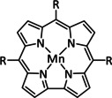
The Schöfberger group reported a Mn–corrole species immobilized on a carbon paper electrode (Table 2, entry 12) via a polyethylene glycol (PEG)‐modified ligand backbone, as an example of a manganese catalyst capable of producing MeOH (FE=23 %) and acetate (FE=63 %). [119] Although a detailed mechanistic investigation has not yet been performed, the authors propose an ETM pathway with a possible MnIII carboxyhydroxyl intermediate towards methanol formation and an oxalate type key species for acetate production.
While manganese catalysts became popular in CO2 reduction most recently, rhenium featured early in this area with a first appearance in the 1980s as [Re(bpy)(CO)3Cl] (Table 3, entry 1a) and is still the metal of choice in some of the most active catalysts reported to date. [26] Wong et al. reported a Faradaic efficiency of almost 100 % in electrolysis experiments with [Re(bpy)(CO)3Cl] at −1.96 V vs. Fc/Fc+ by using TFE as a proton donor. Kinetic studies showed a second‐order dependence of the reaction rate with the acid concentration that supports the proposed reaction mechanism in Scheme 4. Moreover, the authors concluded that water as a Lewis base is not a suitable weak Brønsted acid because it competes with CO2 for the binding site. [122] As described in Section 3.1, Grice et al. came to the same conclusion on the competitive coordination of CO2 and H2O while studying Group 6 transition metals. [49c]
Investigations on the reaction mechanism for the formation of CO by SEC, EPR, Raman spectroscopy, and theoretical calculations confirmed the ETM pathway for the unsubstituted bpy coordinated Re complexes (see methods of Table 3, entry 1a). Most of the catalyst derivatives from this molecular platform (Table 3, entries 1b–i) are expected to follow similar if not identical reaction pathways.
One exception is the tyrosyl‐modified Lehn catalyst described by the Kubiak group, which mediates the reductive disproportionation of CO2 into CO and CO3 2− (Figure 7). [134]
Figure 7.
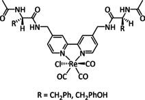
Amino acid functionalized Re–bpy catalysts, reported by Machan et al. [134]
IR‐SEC studies confirmed a mechanistic cycle involving a dimeric species (Scheme 13). The characteristic peaks indicate the mixed‐valence state Re0/ReI in the dimer. Consequently, Re0, with its higher electron density, can coordinate the electropositive carbon atom of the CO2 molecule while the less electronegative ReI metal center coordinates to one of the two oxygen atoms. Insertion of a second CO2 molecule with subsequent CO dissociation yields the carbonate‐bridged Re dimer that separates upon further reduction and releases carbonate or bicarbonate (the latter in the presence of protons). Since only one rhenium center is reduced to the Re0 species, this mechanism is frequently referred to as a one‐electron pathway in the literature.
Scheme 13.
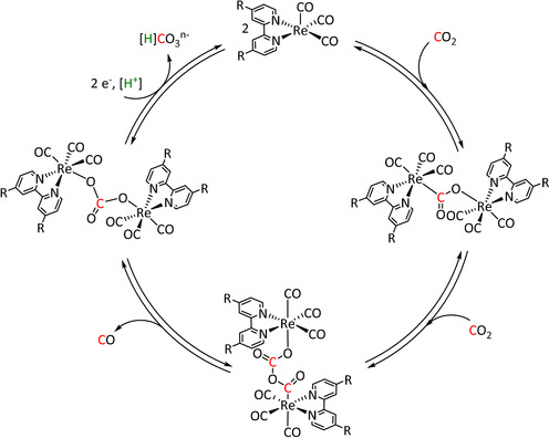
Bimolecular mechanism for the reductive disproportionation of CO2 to CO and CO3 2− by active species of the type [Re(bpy)(CO)3] as proposed by Kubiak and co‐workers. Adapted with permission from ref. [137b]. Copyright 2014 American Chemical Society.
Despite the fact that two Re–bpy complexes are located directly next to each other in the cis conformer of the anthracene‐bridged system reported by the Jurss group (Table 3, entry 1f), it does not catalyze the reduction of CO2 in the manner of the one‐electron pathway. According to their experimental and computational results, the restricted rotation of the Re–bpy fragments does not allow the insertion of a second CO2 molecule. [140] Hofmann degradation of the added tetrabutylammonium conducting salt is likely to be the source of protons and, hence, enables a dimeric version of the previously discussed push–pull mechanism that eventually results in water instead of carbonate as the coupling product (Scheme 14). The authors further propose that the trans conformer follows the same mechanism in a mononuclear reaction pathway. The observed Faradaic efficiencies are in the same range for both isomers (CPE at −2.5 V vs. Fc/Fc+ for 60 min, cis: 81 %, trans: 89 %).
Scheme 14.
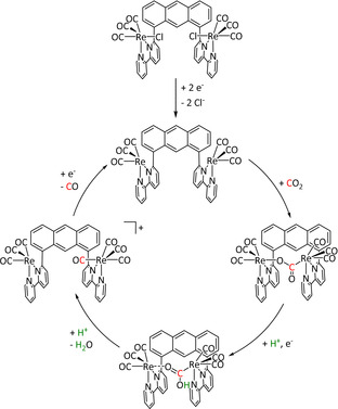
Proposed CO2 electroreduction mechanism for the cis conformer in the study of Yang et al. Adapted with permission from ref. [140]. Copyright 2018 American Chemical Society.
As can be seen from Table 3, the vast majority of the electroreduction catalysts based on Re perform very well in the transformation of CO2 to CO, while the formation of formic acid is only achieved in individual cases. One of them is the alkoxide‐ligated Re compound synthesized by Kumagai et al. (Table 3, entry 1g), which reached 95 % FE for CO production and 27 % for HCO2H generation, depending on the applied conditions. [141] IR spectroscopy and UHPLC were applied to identify intermediates/products in the reaction solution and indicated that only the generation of CO proceeded through the insertion of CO2 into the Re−O bond. For formate generation, the authors proposed an ETH pathway, in which the hydride species originates from reduction and proton binding either directly after the loss of the alkoxide ligand or from a Re–DMF species formed by the association of the solvent.
3.3. Group 8: Fe, Ru, Os
As a general trend, Group 8 elements mark the first transition metals that are capable of yielding products other than carbon monoxide, also in good to excellent Faradaic yields. Both the ETM and ETH pathways seem to be readily accessible for these metals, with the ligand framework as well as the reaction conditions as the factors controlling which of them is preferred.
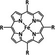
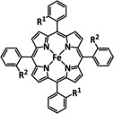
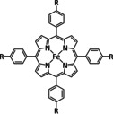
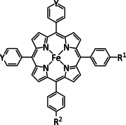
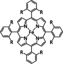
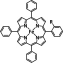
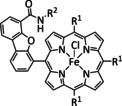
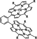
Iron, as one of the cheapest and most abundant transition metals, represents a very selective, efficient, and durable catalyst for CO production when coordinated by porphyrin ligands and environed by a Lewis or Brønsted acid (Table 4, entries 1a–k). [159] Faradaic efficiencies of 100 % can be reached, for example, through the addition of TFE at a potential of −1.46 V vs. NHE (Table 4, entry 1). [77] This could be related to the high electron density of the metal center caused by the four coordinated nitrogen atoms. Therefore, the metal can push more electrons to the carbon of the CO2 molecule, which leads to an accelerated push–pull mechanism and results in the weakening of the C−O bond. [160] A variety of groups investigated this particular type of ETM pathway for Fe porphyrins, but the analysis seems to rely mainly on DFT calculations (Table 4). Francke and co‐workers applied the same method to a cyclopentadienone‐based iron complex complemented by IR‐SEC analysis and even chemical isolation of important species (Table 4, entry 7). [161] Their system was found to catalyze the electrochemical transformation of CO2 to CO with 96 % FE following the mononuclear ETM mechanism, but it can also form an intermediate dimer species bridged by CO ligands (Scheme 15). The addition of protons enables the release of CO and further CO2 coordination. Interestingly, the authors discovered the metal hydride species to be dormant and, hence, did not observe any formic acid.
Table 4.
Catalytic systems, major products, maximum FEs, and mechanisms of Fe complexes in electrochemical CO2 reduction (n.a.=not available, prop.=proposal, comp.=computational investigation, exp.=experimental evidence).
|
Entry |
Cat. system |
Substitution |
Major product |
Max. FE (%) |
Mechanism |
Basis |
Method |
Ref. |
|---|---|---|---|---|---|---|---|---|
|
1a |
|
R=Ph, C6F5, pyren‐1‐yl, meso‐thien‐2‐yl, meso‐5‐methylthien‐2‐yl |
CO/H2O HCO2 − |
100 [160d] 72[a] [164] |
ETM |
DFT |
FeII: FeIII:[b] |
|
|
1b |
|
R1=R2=CO2Me, NHCOtBu, NHCOC6H4CH2MeIm+, NMe3 +, trFc2, trCO2Me, tr‐4‐tBu R1∩R1/R2∩R2=NHCO(CH2)10CONH, NHCO(CH2)10ImCONH |
CO/H2O |
100 [160h] |
ETM |
DFT |
FeII: [166f] FeIII: |
|
|
1c |
|
– |
CO/H2O |
65 |
ETM |
comp. |
DFT |
|
|
1d |
|
R=Ph, pyren‐1‐yl, CO2Me, NMe3 +, SO3 − |
CO/H2O H2 |
100 [160e] 84 [160f] |
ETM |
comp. [160f] |
DFT |
FeII: [167] |
|
1e |
|
R1=CH2CONHC6H3(CF3)2, NHCOCH2C6H3(CF3)2, NHCONH‐Fe‐TPP, OMe R2=H, NH2, OMe Y=CH, N |
CO/H2O CH4 |
90 [169] 41 [163] |
ETM |
comp. [167] |
DFT |
|
|
1f |
|
R=OH, OMe |
CO/H2O |
94 [160c] |
ETM |
prop. |
n.a. |
FeII: [160g] |
|
1g |
|
R=propylpyrene |
CO/H2O |
97 |
n.a. |
n.a. |
n.a. |
|
|
1h |
|
R=CH2CONHC6H3(CF3)2, NHCOCH2C6H3(CF3)2, OH |
CO/H2O |
96 [172] |
ETM |
comp. [167] |
DFT |
FeII: [167] FeIII: [172] |
|
1i |
|
R1=3,4,5‐trimethoxyphenyl R2=CNHNH2, C6H4OH, C6H4SO3H |
CO/H2O |
96 |
ETM |
comp. |
DFT |
|
|
1j |
|
R1=3,4,5‐trimethoxyphenyl R2=3,4,5‐trimethoxyphenyl |
CO/H2O |
100 |
ETM |
prop. |
n.a. |
|
|
| ||||||||
|
1k |
|
R=Ph, Me3C6H2, C6F5, 2,6‐Cl2C6H3, 2,6‐F2C6H3 |
CO/H2O |
92 [175] |
ETM |
prop. [175] |
n.a. |
|
|
2a |
|
L=MeIm |
CO/H2O HCO2 − C2O4 2− |
42 74 11 |
ETM (CO/C2O4 2−) ETH (HCO2 −) |
exp. prop. |
IL,[c] IR‐SEC |
|
|
2b |
|
R1=Me, tBu R2=tBu, OH, OMe R3=tBu, OMe X=–, Cl |
HCO2H H2 |
85 [178] 60 [178] |
ETH |
exp. [179] comp. [179] |
IR‐SEC |
|
|
DFT | ||||||||
|
|
|
|
|
|
|
|
|
|
|
3 |
[Fe4Y(CO)11(L)]n‐ |
L=CO, PPh3, PPh2(CH2)2OH, PPh2C6H4tr n=1, 2 Y=C, N |
HCO2 − H2 |
96±2 [180] 96±6 [181] |
ETH |
exp. [180] |
IL, IR‐SEC, XRD |
|
|
4 |
|
– |
HCO2 − |
80 |
ETM |
comp. |
DFT |
|
|
5 |
[Fe(N∩N)3]2+ |
N∩N=bpy, phen |
CO/CO3 2− |
n.a. |
outer sphere |
exp. comp. |
UV/Vis‐SEC DFT |
|
|
|
|
|
|
|
|
|
|
|
|
6 |
[Fe(tpy)2]2+ |
– |
CO/CO3 2− |
n.a. |
outer sphere |
exp. comp. |
UV/Vis‐SEC DFT |
|
|
7 |
|
R=Me, tBu Y=CH2, C2H4, O |
CO/H2O |
98 [161b] |
ETM |
exp. comp. |
chem. isol., IR‐SEC DFT |
|
|
8 |
|
– |
CO/H2O |
48 |
ETM |
exp. comp. |
IR‐, UV/Vis‐SEC DFT |
|
|
9 |
|
L=H2O, MeCN, CF3SO3 − n=0, 1, 2 R=H, NHEt, NEt2, OH, OMe |
CO/H2O |
81 [185] |
ETM |
comp. [186] |
DFT |
|
|
10 |
[Fe(N2)(dmpe)2] |
– |
CO/CO3 2− |
n.a. |
ETM |
exp. |
IL, NMR, XRD |
|
|
11 |
|
L=MeCN R=Ph |
HCO2 − MeOH[d] |
97 69 |
ETH |
exp. |
IL, NMR |
[a] After addition of Et3N. [b] The metal is coordinated by an axial halide ligand. [c] IL=isotopic labeling. [d] After addition of NHEt2.
Scheme 15.
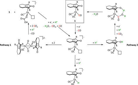
Proposed mechanistic pathways for the electrocatalytic reduction of CO2 using Fe–cyclopentadiones by Oberem et al. (R=SiMe3) Adapted with permission from ref. [161b]. Copyright 2019 American Chemical Society.
Iron complexes bearing porphyrin ligands are also known as electrocatalysts for the formation of formic acid, but no detailed mechanistic studies have been reported as yet. [162] According to a report by the Kraatz group, methane can be produced by Fe porphyrins immobilized on multiwalled carbon nanotubes (MWCNTs) with a FE of 41 %. [163] The group modified the porphyrin ligand framework with pyridyl and anisyl substituents prior to coordination and immobilization, which influences the push–pull mechanism so to reduce the CO2 molecule completely.
Chen et al. reported an iron complex composed of a pentadentate nitrogen ligand (Table 4, entry 4) that yields formic acid in 80 % FE. They concluded from DFT calculations that the formation of HCO2H occurred via the ETM reaction route (Scheme 16). [59] The rationale is that the formal FeIII acts as a poor π‐donor, resulting in a slow C–O cleavage and more facile isomerization that eventually leads to HCO2H formation.
The ETH mechanism has been demonstrated to be operative for the generation of HCO2H at the Fe4 clusters reported by Berben and co‐workers and the dophen/dopy‐based catalysts investigated by Pun et al. as well as Nichols et al. With all three systems the formation of formate is achieved with FEs above 70 % (Table 4, entries 2a,b and 3).[ 177 , 178 , 179 , 180 , 181 , 182 ]
With the help of IR‐SEC, 13C‐labeling, and XRD analysis, as well as thermochemical determinations of acidity, hydricity, and bond energies, the Berben group confirmed pathway A as depicted in Scheme 17.
Scheme 17.
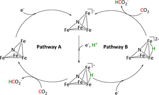
Reaction mechanisms for the reduction of CO2 to HCO2 − by Fe4 clusters proposed by Taheri et al. (CO ligands were omitted for clarity). Adapted with permission from ref. [182d]. Copyright 2018 American Chemical Society.
After a one‐electron reduction, a bridging hydride intermediate forms that acts as the reactive species for the transformation of CO2. By alkynyl functionalization and subsequent cycloaddition to the azide‐terminated glassy carbon, the authors were able to covalently connect the catalyst to the electrode in the form of triazole functionalities. Although a decrease in Faradaic efficiency from >95 % to 75±20 % occurs, an increase in catalyst stability of more than three days compensates for the loss in selectivity. [182e]
Further IR‐SEC and hydricity considerations for [H‐Fe4N(CO)12]2− in pathway B of Scheme 17 ruled out its involvement as the active species for CO2 insertion since the hydricity would favor proton rather than CO2 reduction, which is a contradiction to the catalytic results. [182d] In a further study conducted by the same group, the incorporation of pendant proton donors (PPh2CH2CH2OH) led to increased local proton concentration and a drastic shift to hydrogen as the main product (97 % FE). [181] Furthermore, switching from nitrogen to carbon as the main p‐element in the structure induced a stronger hydride donation, also favoring hydrogen evolution. [182b]
Further mononuclear complexes to generate formic acid involve ONNO ligand frameworks (Table 4, entries 2a,b). While Nichols et al. conducted a series of experimental and computational studies on their system, which strongly support the formation of a Fe–H species and, therefore, the ETH mechanism,[ 167 , 178 ] Pun et al. could not identify the crucial hydride intermediate using IR‐SEC. [177] However, they also concluded the ETH route to be the most plausible pathway because of the detectable hydrogen gas evolution that would be impossible without the same M–H intermediate required for CO2 reduction to HCO2H. Furthermore, no HCO2 − was obtained during control experiments with protonated amines. A piece of additional indirect evidence is the absence of formic acid in the case of an alternative ETM pathway, hence also suggesting the formation of an M–H species to be responsible for the change in the product.
Interestingly, the ONNO‐coordinated complexes investigated by Pun et al. (Table 4, entry 2a) were also capable of producing oxalate to a limited extent of 13 % at −2.0 V vs. Fc/Fc+. At this potential, the iron center exhibits a doubly reduced oxidation state +I, and the ligand system is considered to be innocent as its reduction does not occur before −2.4 V vs. Fc/Fc+. [177] The authors further propose the ETM mechanism as the pathway for oxalate formation but under dissociation of one‐electron‐reduced CO2 and subsequent dimerization.
Another remarkable compound among the iron electrocatalysts is the Fe–triphos entity reported by Bi et al. [188] The group obtained excellent Faradaic yields for HCO2H (97 %) and even 69 % for methanol. However, these results require the addition of HNEt2. On the one hand, it stabilizes the generated formate anion, and on the other hand, it is a crucial part of the carbamic acid intermediate of the MeOH formation (Scheme 18).
Scheme 18.
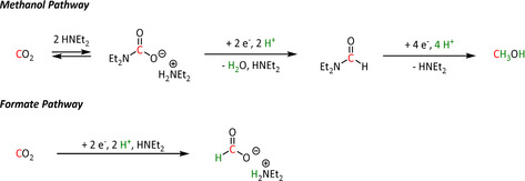
Pathways for electrochemical reduction of CO2 to formate and methanol catalyzed by Fe–triphos as proposed by Bi et al. [188]
Iron's 4d congener, ruthenium, offers the most extensive product portfolio in the electrochemical reduction of CO2. Here once more, bipyridine‐coordinated systems represent the majority of the reported catalysts (Table 5, entries 1a–d). While they are often compared to their Mn and Re analogues and react according to the previously explained ETM route for CO and ETH for formic acid, they are also likely to lose ligands and agglomerate as polymeric structures that deposit on the surface of the working electrode after reduction (Scheme 19). [189]
Table 5.
Catalytic systems, major products, maximum FEs, and mechanisms of Ru and Os complexes in electrochemical CO2 reduction (n.a.=not available, prop.=proposal, comp.=computational investigation, exp.=experimental evidence).
|
Entry |
Cat. system |
Substitution |
Major product |
Max. FE (%) |
Mechanism |
Basis |
Method |
Ref. |
|---|---|---|---|---|---|---|---|---|
|
1a |
[Ru(bpy)(CO)mLo]n+ |
L=Cp, CO2Me, py‐CO2 −, qui, Cl m=0, 1, 2; n=0, 1, 2; o=1, 2 |
CO/CO3 2− CO/H2O H3CCOCH3 [a] |
97 [190] n.a. 70 [194] |
ETM |
comp. [197] |
DFT |
[189, 190, 194, 197, 198] |
|
1b |
|
R1=Me, tBu, pyrrol‐1‐ylethyl, CO2‐iPr, pyrrolylpropyl carbonate R2=Me, tBu, CO2‐iPr, pyrrolylpropyl carbonate |
CO/H2O HCO2H |
100 [189b] 97 [94b] |
ETM (CO) [199] ETH (HCO2H) [199] |
prop. |
n.a. |
[94b, 189b, 198a] |
|
1c |
|
R=Mes, CH2NEt2 |
CO/H2O HCO2H |
95 [67] 9 [136] |
ETH |
exp. |
IR‐SEC |
|
|
1d |
[Ru(di‐R‐bpy)2(CO)mLo]n+ |
L=H, EtOH, qui, 1,8‐napy, Cl m=0, 1, 2; n=0, 1, 2; o=0, 1, 2 R=H, CO2H |
CO/CO3 2− CO/H2O HCO2 − H3CCOCH3 DMF[b] H2 |
78 [195] 88 [200] 84 [201] 16 [195] 21 [196] 51 [201] |
ETM ETH |
exp. [196] comp. [202] exp. [203] |
IR, NMR [196] DFT IR, NMR, UV/Vis |
[195, 196, 200–204] |
|
|
|
|
|
|
|
|
|
|
|
2a |
[Ru(tri‐R1‐tpy)L]n+ |
L=H2O, CH3CN, CO, di‐R2‐bpy, phen‐CO2 −, dmphen,[c] Mebim‐py,[d] pbn, 8‐(diphenylphosphanyl)‐qui, Cl n=1, 2 R1=H, tBu, NO2 R2=H, Me, tBu, OMe |
CO/CO3 2− CO/H2O HCO2 − |
95 [205] 85 [206] 42 [191] |
ETM |
comp. [207] |
DFT |
[191, 192, 205–208] |
|
|
|
|
|
|
|
|
|
|
|
2b |
[Ru(4‘‐R‐tpy)(L)(X)]n+ |
L=bpy, tpy n=1, 2 R=H, 4‐(tert‐butyl‐phenyl)‐1H‐1,2,3‐triazol‐4‐yl X= –, Cl |
CO/H2O HCO2 − H2 |
38 10 33 |
ETM |
prop. |
n.a. |
|
|
2c |
|
R=PO3H2, PO3Et2 |
CO/H2O |
63 |
ETM |
prop. |
n.a. |
|
|
2d |
|
N∩N∩N=tpy |
CO/CO3 2− |
22 |
n.a. |
n.a. |
n.a. |
|
|
2e |
|
Y=CH, NMe |
CO/CO3 2− |
35 |
ETM |
exp. |
IR‐SEC |
|
|
3 |
|
– |
CO/CO3 2− |
97 |
ETM |
comp. |
DFT |
|
|
4a |
|
Y=CH, N |
HCO2 − H2CO MeOH |
n.a. |
ETH |
exp. |
IR‐SEC |
|
|
4b |
|
– |
CO/CO3 2− |
96 |
ETM |
comp. |
DFT |
|
|
5 |
|
L=bpy |
HCO2 − C2O4 2− |
90 70 |
ETM |
exp. |
IL, IR‐SEC |
|
|
6a |
|
R=H, Me |
CO/H2O HCO2 − H2 |
19 25 24 |
ETM (CO) ETH (HCO2 −) |
prop. |
n.a. |
|
|
6b |
|
X= –, Cl |
CO/H2O HCO2 − H2 |
73 40 27 |
ETM (CO) ETH (HCO2 −) |
prop. |
n.a. |
|
|
6c |
|
R=C6H4OMe |
CO/CO3 2− |
53 |
ETM |
comp. |
DFT |
|
|
6d |
|
R=C6H4OMe |
CO/CO3 2− |
25 |
ETM |
comp. |
DFT |
|
|
7 |
[Os(CO)(di‐R‐bpy)(L)Cl2] |
R=H, CH3, tBu, CO2‐iPr L=CO, PrCN, Cl |
CO/CO3 2− HCO2 − |
60 [219] 48 [219] |
n.a. |
n.a. |
n.a. |
|
|
|
|
|
|
|
|
|
|
|
|
8 |
[Os(CO)(bpy)2H]+ |
– |
CO/H2O HCO2 − |
90 [221] 25 [221] |
ETM |
exp. |
IL |
[a] After addition of (CH3)4NBF4. [b] After addition of HNMe2. [c] 2,9‐Dimethyl‐1,10‐phenanthroline. [d] 1‐Methylbenzimidazol‐2‐ylidene‐3‐(2′‐pyridine).
Scheme 19.
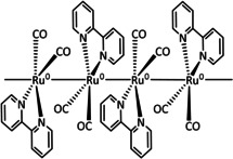
Electrodeposited [Ru(bpy)(CO)2]n polymer film described by Chardon‐Noblat et al. Adapted with permission from ref. [190a]. Copyright 1997 American Chemical Society.
As discussed before, ETM traverses a metal‐bound hydroxycarbonyl resulting from an η1‐CO2 coordination with subsequent protonation. In contrast, the ETH pathway comprises the HCO2 − intermediate as the result of CO2 insertion into the M−H bond. Machan et al. postulated for a mesityl‐modified Ru–bpy complex (Table 5, entry 1c) that these are not two separate reaction pathways but can be interrelated via isomerization of the intermediates. Indeed, the formate adduct can isomerize to the hydroxycarbonyl, which can then undergo proton‐induced dehydration. This ultimately results in CO evolution from a crossing between the intermediates of the ETH and ETM mechanism, as depicted in Scheme 20. [67]
Chemical participation of the ligand framework in the reduction process was reported by Ghosh et al. in the case of Ru–tpy compounds bearing a second 2‐(pyridin‐2‐yl)benzo[b][1,5]naphthyridine (pbn) building block. The dearomatization of the pbn unit was observed and is believed to provide the required H equivalents for the reduction of CO2 to HCO2 − without the formation of a metal hydride (Scheme 21). [191]
Scheme 21.
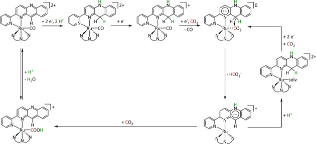
Catalytic cycle for the electrochemical reduction of CO2 by the Ru–pbn type complex proposed by Ghosh et al. Adapted with permission from ref. [191]. Copyright 2017 American Chemical Society.
The authors were able to identify crucial mechanistic intermediates by mass spectrometry. Furthermore, they succeeded in isolating a relevant catalytic intermediate by reducing the starting complex with cobaltocene. This species comprising a carbonyl ligand bound between the pbn fragment and the Ru center takes part in the reaction mechanism as depicted in Scheme 22.
Scheme 22.
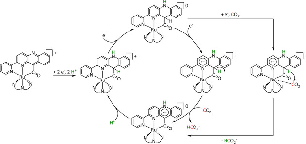
Catalytic cycle for the electrochemical reduction of CO2 by the chemically reduced Ru–pbn type complexes proposed by Ghosh et al. Adapted with permission from ref. [191]. Copyright 2017 American Chemical Society.
A ruthenium complex bearing a pyridyl‐carbene ligand in addition to tpy was studied by Gonell et al. (Table 5, entry 2a). [192] According to the authors, the rate constant for CO2 reduction is slightly higher when the strong electron‐donating carbene is located in trans‐position (C‐trans) to the substrate than when the pyridine nitrogen is in this position (N‐trans, k=2400 s−1 vs. 2100 s−1). Further kinetic considerations based on CV measurements confirmed that the N‐trans complex undergoes isomerization after the initial two‐electron reduction and is not an active CO2‐electroreduction catalyst. From this point on, the generation of CO follows the ETM pathway (Scheme 23). Further insight on the details of the mechanism can be found in the respective follow‐up report of the group. [193] They provide an extensive kinetic study with a focus on the trans effect of carbonyl ligands on the electronic structure of the metal center.
Scheme 23.
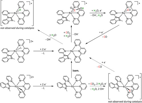
Overall mechanistic scheme for CO2 reduction by Ru‐tpy‐pyridyl‐carbene complexes as proposed by Gonell et al. (L=MeCN). Adapted with permission from ref. [192]. Copyright 2019 American Chemical Society.
Concerning products with higher molecular complexity, the complex [Ru(bpy)(napy)2(CO)2](PF6)2 (napy=1,8‐naphtyridine; Table 5, entry 1d) was reported by Mizukawa et al. to produce acetone selectively by electrocatalytic CO2 reduction. [194] The authors based their choice of ligand on the comparable mechanistic study with the mono‐napy species described by Nakajima et al. [195] After a first one‐electron reduction, the non‐bonded napy nitrogen nucleophilically attacks the CO carbon (Scheme 24). This was deduced from a bathochromic shift of 418 cm−1 of the CO band using IR spectroscopy. The involvement of the second napy nitrogen suppresses the cleavage of the carbonyl ligand and makes it available for further reactions. It is proposed that the conducting ion (CH3)4N+ acts as a methylation agent. The reaction is reported to take place at potentials of only −1.4 V vs. Ag/Ag+ with yields of 70 % FE, but a temperature of 100 °C is required. [194]
Scheme 24.
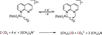
One‐electron reduction of [Ru(bpy)2(napy)(CO)]2+ and nucleophilic attack on the carbon atom. [194]
For the generation of DMF from CO2, Ishida et al. used the substrate dimethylamine and Na2CO3 in acetonitrile with [Ru(bpy)2(CO)2]2+ as catalyst (Table 5, entry 1d). The formation of a carbamoyl complex [Ru(bpy)2(CO)(CONMe2)]+ by nucleophilic attack of Me2NH at a CO ligand in the catalytic cycle (Scheme 25) was inferred from characteristic shifts of the CO bands in the IR spectrum and the proton signals of the two methyl groups using low‐temperature 1H NMR spectroscopy. However, the complex could not be isolated due to the reversible coordination reaction of the dimethylamine, as proposed by the authors. When CPE at −1.30 V vs. SCE was performed, a FE of 21 % for DMF was obtained, while formate (76 % FE) was the main product. [196]
Scheme 25.
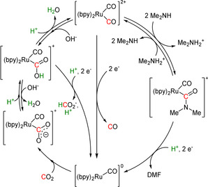
Mechanism for the electrocatalytic reduction of CO2 to formate or DMF with [Ru(bpy)2(CO)2]2+ proposed by Ishida et al. [196]
The Tanaka group presented a dimeric ruthenium complex capable of forming oxalate with a maximum Faradaic yield of 70 % (Table 5, entry 5). [216] Interestingly, based on the IR‐SEC results, the authors opposed the outer‐sphere mechanism and proposed the dechelation of the ligand instead, allowing a twofold ETM pathway facilitating the association of the activated CO2 molecules.
Compared to ruthenium, only very few examples of osmium catalysts are known for CO2 reduction (Table 5, entries 7 and 8). These complexes are composed of CO/bpy ligand combinations and exhibit Faradaic yields for CO of up to 90 %. [221] Similar to the ruthenium complexes summarized in Table 5, entry 1a, Castillo et al. reported the electropolymerization of the osmium complex at the electrode surface. [219] Moreover, they proposed that at low catalyst loadings, the predominance of monomeric OsI species is responsible for CO generation, while at higher concentrations the formation of dimeric species results in HCO2 − production. The latter occurs in particular after the introduction of electron‐withdrawing substituents into the ligand framework.
3.4. Group 9: Co, Rh, Ir
En route to the late transition metals, cobalt‐based catalysts mostly lead to the formation of carbon monoxide, but frequently formic acid can also be observed as the product (Table 6). There are examples of the generation of both products with Faradaic efficiencies close to 100 % (Table 6, entry 3c for CO, and entry 10a for HCO2H). Available mechanistic studies are most consistent with a clear distinction, where CO evolution proceeds via ETM mechanism while HCO2H formation occurs via the ETH route.
Table 6.
Catalytic systems, major products, maximum FEs, and mechanisms of Co complexes in electrochemical CO2 reduction (n.a.=not available, prop.=proposal, comp.=computational investigation, exp.=experimental evidence).
|
Entry |
Cat. system |
Substitution |
Major product |
Max. FE (%) |
Mechanism |
Basis |
Method |
Ref. |
|---|---|---|---|---|---|---|---|---|
|
1a |
|
n=1, 2 R= –, H, Me X= –, MeCN, NCS, Cl, Br |
CO/H2O H2 |
45±7 [235] 30±8 [235] |
ETM |
exp.[236 comp. [237] |
IL, IR DFT |
|
|
1b |
|
– |
CO/H2O |
82 |
ETM |
comp. |
DFT |
|
|
1c |
|
– |
HCO2H |
80 |
ETM (CO) ETH (HCO2H) |
exp. comp. |
IR‐SEC DFT |
|
|
1d |
|
– |
HCO2H |
60 |
n.a. |
n.a. |
n.a. |
|
|
2a |
|
R=H, Me |
CO/H2O H2 |
93 (CO+H2) |
ETH |
prop. |
n.a. |
|
|
3a |
|
Ar=Ph, C6H4CF3, C6H4NH2, C6H4NMe3 +, C6H3(OH)2, C6H4OMe, C6H3(OMe)2, C6H4Cl, C6H4Br, C6H4F, C6F5 n=0, 1 X= –, Cl |
CO/H2O |
97 [242] |
ETM |
prop. [242] |
n.a. |
|
|
3b |
|
– |
CO/H2O |
89 |
ETM |
prop. |
n.a. |
|
|
3c |
|
R1=H, tBu, OC8H17, O‐py R2=H, tBu, OC8H17, O‐py R3=H, NMe3 + |
CO/H2O H2 MeOH |
100 [120] 72 [120] 20 [231] |
ETM |
exp. [230] comp. [245] |
PSCAS DFT |
[120, 230, 231, 243e, 245, 246] |
|
3d |
|
– |
CO |
97 |
n.a. |
n.a. |
n.a. |
|
|
4 |
|
L=PPh3 R=S‐(PEG7)‐OCH3 |
HCO2 − CH3OH H2CO CH3CH2OH CH3CO2 − H2 |
12 59 10 48 13 36 |
ETM |
exp. |
EPR, GC‐MS, IL, IR‐SEC, NMR |
|
|
5a |
|
– |
CO/H2O |
77 |
n.a. |
n.a. |
n.a. |
|
|
5b |
|
R=CH3 R∩R=CH2, (CH2)2 |
CO/H2O |
98 |
ETM |
comp. |
DFT |
|
|
5c |
|
n=0, 1 X= –, Cl |
CO/H2O |
16 |
ETM |
exp. comp. |
IR, UV/Vis DFT |
|
|
6 |
|
R=H, Me, allyl |
CO/H2O |
98 |
ETM |
comp. |
DFT |
|
|
7 |
|
L=py, qui (+ dimer) |
CO/H2O |
84 |
ETM |
comp. |
DFT |
|
|
8 |
|
R1=H, tBu, OMe, p‐Me‐C6H4, p‐Cl‐C6H4 R2=H, tBu |
CO/H2O H2 |
37 [253] 23 [253] |
ETM |
prop. [253] |
n.a. |
|
|
9 |
[Co(PPh3)2L]n+ |
L=4,4′‐di‐Me‐bpy, 4‐Me‐1,10‐phen, 2‐Me‐8‐hydroxyqui n=1, 2 |
CO/CO3 2− HCO2 − |
83 44 |
ETM |
prop. |
n.a. |
|
|
|
|
|
|
|
|
|
|
|
|
10a |
[CoCp(L)I]+ |
R1=Cy, Ph R2=Ph, Bn |
HCO2 − H2 |
99±8 67±5 |
ETH |
comp. |
DFT |
|
|
|
|
|
|
|
|
|
|
|
|
10b |
|
n=1, 2 R=H, Me X=MeCN, I |
CO/H2O |
70 |
ETM |
prop. |
n.a. |
|
|
11a |
|
– |
CO/H2O |
94 [184] |
ETM |
prop. [184] |
n.a. |
[184, 229, 258] |
|
11b |
|
Y=CH2, (CH2)2, (CH2)3 |
CO/H2O HCO2H |
104±6 [259] 23 [260] |
ETM |
prop. |
n.a. |
|
|
12 |
|
– |
CO/H2O |
96 |
ETM |
comp. |
DFT |
|
|
13a |
|
– |
CO/H2O |
95±2 |
ETM |
comp. |
DFT |
|
|
13b |
|
L∩L=dppe, bpy, 4,4'‐(OMe)2bpy, 2‐pyridinethiolato n=0, 1 |
CO/H2O HCO2H H2 |
92±4 [263] (CO+H2) 64 [264] 19 [264] |
ETM (CO) ETH (HCO2H/H2) |
comp. |
DFT |
|
|
14 |
|
– |
n.a. |
n.a. |
ETM |
exp. comp. |
XRD coupled cluster |
|
|
15 |
[Co(L)2]2+ |
|
CO/H2O H2 |
23 42 |
ETM (CO) ETH (H2) |
prop. |
n.a. |
|
|
16 |
|
R=MeCp |
C2O4 2− |
80 |
n.a. |
n.a. |
n.a. |
The vast majority of the cobalt catalysts in the literature are based on tetradentate nitrogen ligands and produce almost exclusively CO during CO2 electroreduction. Here, predominantly macrocyclic ligands (porphyrins, phthalocyanines, corroles, cyclams, etc.) coordinate the cobalt center.[ 159b , 159c ] So far, cobalt porphyrins (CoP, Table 6, entry 3a) were the objects of considerable interest in several mechanistic DFT studies. [223] In particular, the Koper group investigated the pH‐dependent mechanism of the formation of the [Co–CO2H] adduct as a crucial intermediate in the ETM pathway towards CO. [224] They found that two subpathways need to be distinguished: the concerted proton–electron transfer (CPET), which is often associated with solid‐state metal catalysts and the sequential proton–electron transfer (SPET) usually connected with molecular systems. Furthermore, the computational studies identified certain pH thresholds for CoP at which a switch from CPET to a mixed CPET–SPET regime is possible, even for homogeneous systems (Figure 8).
Figure 8.
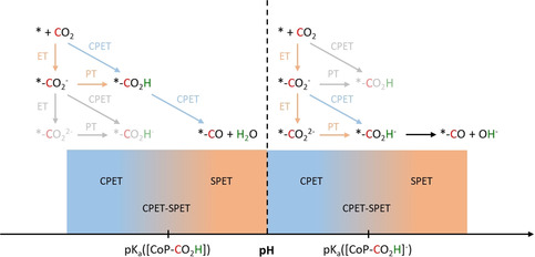
Schematic depiction of the dominant mechanism for the formation of the carboxylate intermediate depending on the pH as proposed by Göttle et al. (PT=proton transfer, ET=electron transfer, CPET=concerted proton‐electron transfer, SPET=sequential proton‐electron transfer). [224b]
The border between the two regimes for a possible [CoP–CO2H] intermediate is located at pH≈3.5, corresponding to the pK a of the hydroxycarbonyl species. At higher pH values, the involvement of the neutral species is unlikely, and [CoP–CO2H]− becomes a conceivable intermediate. At pH values of up to approximately 8.6, the formation of [CoP–CO2H]− from [CoP–CO2]− by CPET is favored. Above this, [CoP–CO2]2− and a SPET reaction are believed to form [CoP–CO2H]−. Overall, this investigation emphasized the effect of the pH value on the mechanistic pathways during electrocatalytic CO2 reduction.
Also, Yao et al. investigated a Co–porphine system theoretically and suggested that the required proton for [CoP–CO2H]− formation does not originate from the solution when CO2 is reduced, but that it is held by the pyrrole ligand at pH values below 6.94. [225] This results in the reaction sequence displayed in Scheme 26.
Scheme 26.

Reaction sequence for electrocatalytic CO2 reduction to CO with cobalt porphines proposed by Yao et al. [225]
In this way, the pyrrole‐adsorbed proton acts in analogy to the frequently used phenol proton donor groups (e.g., ‐C6H4OH). Hence, the local proton concentration near the active center is increased, which enhances catalysis following the ETM route.
Another involvement of ligand‐based protons in the catalytic cycle can be observed for the azacalix[4](2,6)‐pyridine ligand framework, allowing FEs of 98 % for CO production (Table 6, entry 6). The Marinescu group investigated this class of aminopyridine macrocycles and the effect of the proton or the methyl group bound to the pendant amines, respectively. On switching to the alkyl group, CV and CPE experiments showed a dramatic decrease of Faradaic efficiency (98→23 %), turnover number (1.22×10⁶→3.60×10³), and turnover frequency (170→0.5 s−1), but a significant increase of reduction potential to generate the active Co0 species (−2.36→−2.58 vs. Fc/Fc+). [226] They attribute this behavior to H‐bonds stabilizing the coordinated CO2 molecule during the ETM pathway, as depicted in Scheme 27. Fujita et al. further confirmed the presence of intermolecular H‐bonds by IR spectroscopy. [227]
Scheme 27.
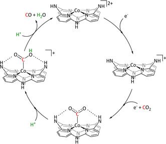
Mechanism for the H‐bond stabilized reduction of CO2 by Co–aminopyridine macrocycles proposed by Chapovetsky et al. (coordinated solvent molecules were omitted for clarity). Adapted with permission from ref. [226]. Copyright 2016 American Chemical Society.
Combined computational and experimental investigations by Roy et al. focused on the reductive disproportionation of CO2 on a masked two‐coordinate cobalt(I) complex without the involvement of protons. [228] The initially isolated and characterized κN,η6‐arene isomer (Table 6, entry 14) was theoretically found to undergo isomerization during the course of the reaction, leading to a κ2 N,N′‐bound Co center. The authors were able to confirm the computational results for this active tBuLCoOCoLtBu (LtBu=2,2,6,6‐tetramethyl‐3,5‐bis[(2,6‐diisopropylphenyl)imino]hept‐4‐yl) species by independent chemical synthesis and analysis. The bridging oxygen atom exhibits a sufficiently high negative charge to act as a nucleophile, which ultimately results in the activation of CO2 in the form of a carbonate complex. However, the authors do not report any catalytic data for the system, indicating that no carbonate release is taking place.
A phenomenon frequently occurring for Co catalysts is the deposition on the electrode surface, either as an intended strategy or unwanted side reaction. The quaterpyridine‐coordinated complexes investigated by the Che group in the mid‐1990s (Table 6, entry 11a) were found to electropolymerize onto the electrode surface in a comparable manner to the aforementioned Ru–bpy complexes. [229] The reported maximum FE of >90 % for CO evolution can be attributed, at least in part, to a polymeric species bound to the electrode surface since transferring the electrode to a catalyst‐free solution still showed a Faradaic efficiency of approximately 35 %.
Abe et al. modified a cobalt phthalocyanine complex (CoPc) with butoxy groups and isolated the resulting octabutoxyphthalocyanine compound (CoPc(BuO)8, Table 6, entry 3c). [230] Initial CPE experiments showed that the catalyst exhibited a twentyfold increase in TOF compared to CoPc, which they attributed to the higher electron density at the metal center due to the positive inductive effect of the alkoxide chains. In situ potential‐step chronoamperospectroscopy (PSCAS) helped to identify the ETM mechanism. A poly(4‐vinylpyridine) (PVP)‐based membrane containing the modified CoPc complex was prepared, but the expected further increase in activity did not occur. After CPE for 1 h at −1.30 V vs. Ag/AgCl and pH 4.4, the immobilized complex produced only 10 % of the amount of CO produced by the molecular catalyst. Concomitantly, H2 evolution increased, which eventually led to a ratio of CO/H2 of approximately 0.5.
Boutin et al. used CoPc on MWCNTs (Table 6, entry 3c) for the electrocatalytic formation of methanol from CO2 in a two‐step process. [231] After the first two‐electron reduction of CO2 to CO (FE=95 %), further reduction to MeOH at a pH value of 13 with the same catalyst was achieved with an overall Faradaic efficiency of 19.5 %. The authors reported formaldehyde as a key intermediate in the transformation and indicate that the Cannizzaro reaction might be the possible origin of a small fraction of the produced methanol at the applied pH values.
The recent reports concerning electrochemical CO2 reduction by CoPc and its derivatives immobilized on carbon nanotubes led Wu et al. to investigate the nature of this group of catalysts in more detail. Under aqueous conditions, electrochemical studies combined with rinse tests and UV/Vis investigations of the electrolyte strongly indicated the heterogeneous rather than homogeneous character of the involved catalytic species. [232] Further insights on the mechanisms for CoPc in the electrochemical reduction of CO2 can be found elsewhere in the literature. [233]
As another example for immobilized Co macrocycles in electrochemical CO2 reduction, the polyethylene glycol derivatized Co–corrole (Figure 9; Table 6, entry 4) reported by Gonglach et al. showed remarkable catalytic activity when used on carbon paper electrodes. [234] More specifically, it produces ethanol and methanol in a Faradaic efficiency of 47 and 59 %, respectively, at −0.73 V vs. reverse hydrogen electrode. Employment of GC‐MS (in combination with 2D‐ and 13C‐labeling), NMR, EPR, IR‐SEC, and complementary control experiments resulted in the proposed mechanism(s) presented in Figure 10.
Figure 9.
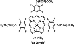
Co–corrole reported by Gonglach et al. [234]
Figure 10.
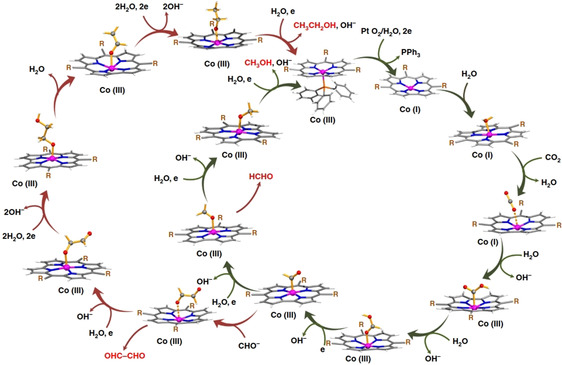
Single‐site mechanism of CO2 reduction using Co–corrole proposed by Gonglach et al. Reprinted with permission from ref. [234]. Copyright 2019 Springer Nature.
Isotope labeling, in combination with GC‐MS assisted product analysis, confirmed water as the proton source and CO2 as the origin of the carbon atoms. EPR investigations hinted at a CoIII–CO2 .− intermediate originating from the reduction of CO2 by a cobalt(I) species. Subsequent proton‐coupled electron transfers (PCETs) give a HCO2H intermediate stable enough for NMR analysis. Subsequent one‐electron reduction and simultaneous dissociation of OH− leads to an HCO. intermediate stabilized by a CoIII center, which constitutes a mechanistic bifurcation. While one further PCET allows formaldehyde generation, a second one gives methanol as the main product. In the other direction, dimerization yields oxaldehyde as a key intermediate that undergoes several PCETs to give ethanol as the second most generated product. External addition of OHC‐CHO under the initial reaction conditions resulted in an increased formation of EtOH and confirmation of its role as a key intermediate.
In contrast to its 3d equivalent cobalt, rhodium shows a highly preferred reactivity for the electrochemical generation of formate (Table 7). Bidentate phosphine (Table 7, entry 1) and nitrogen‐based ligands (Table 7, entries 2a,b and 5) constitute the most frequently used coordination environments. Faradaic yields in the range of 80 % are observed for complexes coordinated by two tridentate nitrogen‐containing ligands (Table 7, entries 3 and 4). Interestingly, the initial RhIII species is activated by a single two‐electron reduction in the potential range of −0.42 V to 0.98 V vs. SCE under an inert atmosphere, but a splitting of the reduction wave into two one‐electron steps was observed after the addition of CO2. This behavior indicates an interaction of CO2 with the metal ion at a very early stage of the reaction pathway. The CO2 reduction by RhI in the next step occurred (depending on the exact ligand structure) at remarkably low potentials between −1.28 V and −1.44 V vs. SCE. [267]
Table 7.
Catalytic systems, major products, maximum FEs, and mechanisms of Rh complexes in electrochemical CO2 reduction (n.a.=not available, prop.=proposal, comp.=computational investigation, exp.=experimental evidence).
|
Entry |
Cat. system |
Substitution |
Major product |
Max. FE (%) |
Mechanism |
Basis |
Method |
Ref. |
|---|---|---|---|---|---|---|---|---|
|
1 |
[Rh(dppe)2Cl] |
– |
HCO2 − |
42 |
ETM |
exp. |
Chemical isolation |
|
|
2a |
cis‐[Rh(bpy)2(CF3SO3)2]+ |
– |
HCO2 − Bu3N H2 |
83 [269] 59 [269] 29 [269] |
ETM |
prop. |
n.a. |
|
|
2b |
|
– |
HCO2 − H2 |
49 32 |
ETH |
prop. |
n.a. |
|
|
3 |
|
L=Cl L∩L∩L=2,4,6‐tris(2‐pyridyl)‐1,3,5‐triazine n=0, 3 |
HCO2 − |
82 |
n.a. |
n.a. |
n.a. |
|
|
4 |
|
L=Cl; L∩L=pyCONH2 L∩L∩L=bis‐(2‐pyridylcarbonyl)amide, tpy n=1, 2 |
HCO2 − |
78 |
n.a. |
n.a. |
n.a. |
|
|
5 |
[Rh2L2(N∩N)2]2+ |
L=p‐ditolylformamidinate N∩N=phen, dipyrido[3,2‐f:2′,3′‐h]quinoxaline) |
HCO2 − H2 |
12 77 |
ETH |
prop. |
n.a. |
When the Wagenknecht group investigated the Rh(diphos)2 catalyst and observed formate production, they were able to isolate the hydride HRh(diphos)2. [268] However, although this species may constitute the reactive intermediate of an ETH pathway, they claimed ETM to occur predominantly. This assertion was supported by 1) control experiments of the isolated Rh‐H with CO2 indicating a very slow reaction and 2) decreasing current efficiencies during more extended reaction periods, hinting towards the build‐up of the hydride as a dormant species. Interestingly, control experiments in benzonitrile supported the claim of acetonitrile as the proton source in this reaction, because formate production decreased by 50 %. Moreover, small amounts of cyanoacetate as the reaction product between NCCH2 − and CO2 were detected in GC‐MS analysis. Summarizing these findings, the authors proposed the mechanism in Scheme 28 with the predominant formation of formate via the ETM pathway.
Scheme 28.

Mechanisms for electrochemical CO2 reduction by Rh(diphos)2 as proposed by Slater et al. Adapted with permission from ref. [268]. Copyright 1984 American Chemical Society.
cis‐[Rh(bpy)2(CF3SO3)2]+ exhibits the highest FE for HCO2H of the Rh complexes studied so far, with 83 % (Table 7, entry 2a). [269] Bolinger et al. proposed an ETM pathway in this case as well. According to their report, the tetrabutylammonium salt undergoes Hofmann degradation generating the required protons for the formation of HCO2H and butene as well as tributylamine as coproducts. Furthermore, they conjecture that only M–CO2 binding involving extensive electron donation from the metal to CO2 would make the oxygen ends sufficiently basic to allow an attack on the tetrabutylammonium salt.
In contrast, the reports of Caix et al. and Witt et al. suggest a metal hydride intermediate to be responsible for the generation of formate per the expected ETH route. Despite the lack of spectroscopic or computational investigation (which seems recurrent for reports on Rh‐catalyzed CO2 reduction), they support their hypothesis with the concomitant evolution of H2 as evidence for a Rh–H intermediate crucial for both reactions. [270] Caix et al. summarized their proposal in the catalytic cycle shown in Scheme 29. [270a]
Scheme 29.
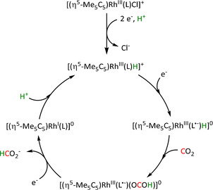
Rhodium‐catalyzed production of formate via an ETH mechanism proposed by Caix et al. [270a]
Iridium shows similarities to rhodium with respect to the product scope. A modified [Ir(tpy)(2‐phenylpyridine)Cl]+ complex (Table 8, entry 5) is capable of generating carbon monoxide, [272] but the determined FE of 45 % is low compared to values of 97 % for formate production when iridium PNP pincer‐type complexes (Table 8, entry 3) are used. This class of catalysts strongly tends towards HCO2H production rather than CO formation. [273] Coordination spheres containing triphenylphosphine (Table 8, entry 1) or bpy moieties (Table 8, entry 4) lead to lower values. From a mechanistic standpoint, the ETH route is proposed unanimously in the case of iridium, and DFT, as well as NMR studies, support these claims. In several cases, isolated hydride species even constitute the stable catalyst precursor for the electrochemical CO2 reduction. Furthermore, as reported by Kang et al. in 2012, they maintained their stability during the formation of formate in the presence of water as the proton source (Table 8, entry 2a). [274] In this case, the hydroxide anion forms bicarbonate as a coproduct along with formate (Scheme 30). The stability of hydride species of 4d and 5d transition metals in an aqueous environment may be responsible in part for the shift from mainly CO as a product in Groups 6, 7, and 8 of the periodic table to formic acid in the later periods of Group 9.
Table 8.
Catalytic systems, major products, maximum FEs, and mechanisms of Ir complexes in electrochemical CO2 reduction (n.a.=not available, prop.=proposal, comp.=computational investigation, exp.=experimental evidence).
|
Entry |
Cat. system |
Substitution |
Major product |
Max. FE (%) |
Mechanism |
Basis |
Method |
Ref. |
|---|---|---|---|---|---|---|---|---|
|
1 |
[IrCl(CO)(PPh3)2] |
– |
CO/H2O HCO2 − |
n.a. n.a. |
ETH |
prop. |
n.a. |
|
|
2a |
|
L=H, MeCN n=0, 1 R=H, pyr, 4,4‐dimethyl‐1‐piperazinium+ Y=CH2, O |
HCO2 − H2 |
96 [277] 15 [274] |
ETH |
exp. [274] comp. [278] |
NMR DFT |
[274, 277–279] |
|
2b |
|
Y=CH2, NH, O |
CO/H2O |
98 |
n.a. |
n.a. |
n.a. |
|
|
2c |
|
– |
HCO2 − |
97 |
ETH |
exp. |
NMR |
|
|
3 |
|
– |
HCO2 − |
97 |
ETH |
exp. |
NMR |
|
|
4 |
|
R1=H, Me, NH2, OMe R2=H, Me, tBu, OMe R3=H, CO2Et, CONH(p‐tolyl), OMe |
HCO2 − |
44 |
ETH |
prop. |
n.a. |
|
|
5 |
|
L=MeCN n=1, 2 Y=N, C |
CO/CO3 2− HCO2 − |
100 10 |
ETH |
comp. |
DFT |
|
|
6 |
|
R=Cp* |
C2O4 2− |
60 [275] |
ETM |
exp. |
IL, IR‐SEC |
Scheme 30.
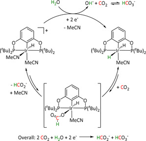
Mechanism for electrocatalytic CO2 reduction by Ir–POCOP pincer hydride complexes as proposed by Kang et al. Adapted with permission from ref. [274]. Copyright 2012 American Chemical Society.
The complex [(Ir‐(η5‐C5Me5))3(μ3‐S)2]2+ ([Ir3S2]2+) reported by Tanaka et al. (Table 8, entry 6) is capable of forming oxalate, whereby the nature of the Ir cluster appears to play a special role (Scheme 31). After a two‐electron reduction to [Ir3S2]0, a first equivalent of oxalate is generated. The obtained molecular structure of intermediate [Ir3S2CH2CN]+ is then formed by the addition of linear CH2CN− at the exo‐position of one Cp* ligand. This Cp* derivative coordinates to one of the Ir atoms in an η4‐fashion to generate the active species, ultimately leading to oxalate formation after twofold CO2 association and electron uptake. The IR spectroscopic analysis showed the reversibility of the first CO2 adduct formation. During CPE at −1.55 V vs. Ag/Ag+, a Faradaic efficiency of 64 % was determined. [275] Extensive IR‐SEC and isotope‐labeling studies led to the conclusion that instable {[Ir3S2CH2CN](CO2)2]}− represents the active species of the catalytic cycle, indicating an ETM route. Presumingly, Ir–Ir bond cleavage is necessary to open a coordination site and enable the electrophilic attack of the second CO2 molecule.
Scheme 31.
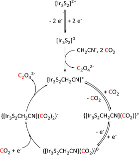
Mechanism of the electrocatalytic formation of oxalate by [(Ir‐(η5‐C5Me5))3(μ3‐S)2]2+. Adapted with permission from ref. [275]. Copyright 1998 American Chemical Society.
3.5. Group 10: Ni, Pd, Pt
One of the most renowned and effective catalytic systems for electrocatalytic CO2 reduction is the complex (1,4,8,11‐tetraazacyclotetradecane)nickel(II) or [NiII(cyclam)]2+ (Table 9, entries 2a–h). In 1984, the Sauvage group reported on [NiII(cyclam)]2+ and found almost quantitative selectivity towards CO at exceptionally low potentials of −1.00 V vs. NHE in H2O. [283] Since then, extensive studies on the reaction mechanism, the role of the electrode, and possible deactivation pathways have been performed.
Table 9.
Catalytic systems, major products, maximum FEs, and mechanisms of Ni complexes in electrochemical CO2 reduction (n.a.=not available, prop.=proposal, comp.=computational investigation, exp.=experimental evidence).
|
Entry |
Cat. system |
Substitution |
Major product |
Max. FE (%) |
Mechanism |
Basis |
Method |
Ref. |
|---|---|---|---|---|---|---|---|---|
|
1 |
|
R= –, H |
CO/H2O |
44 [241a] |
ETH |
prop. [241a] |
n.a. |
|
|
2a |
|
R1=H, Me; R2=H, propyl, Bn, (CH2)2OH, CO2H, NH2, R3=H, Me2, Ph, tolyl, C6H4CF3 R4=R5=H, Me, Me2 R4∩R5=Cy Y=NH, NMe Z=CH, N |
CO/H2O HCO2 − H2 |
99 [283] 75 [54a] 53 [296] |
ETM (CO) ETH (HCO2H) |
exp. comp. [297] |
IR‐SEC, [292] DFT |
[54a, 62b, 241, 283, 284, 287, 291, 292, 296–299] |
|
|
|
|
|
|
|
|
|
|
|
2b |
|
|
CO/H2O H2 |
54 89 |
n.a. |
n.a. |
n.a. |
|
|
2c |
|
n=0, 2 (C6H4‐bridged), 3, 4, 6 R=H, Me Y=CH, N |
CO/H2O HCO2 − |
95 [299g] 68 [54a] |
ETM (CO) ETH (HCO2H) |
prop. [54a] comp. [299g] |
n.a. DFT |
|
|
2d |
|
– |
CO/H2O H2 |
79 (com‐ bined) |
ETM |
prop. |
n.a. |
|
|
2e |
|
R1=Me, Ph R2=H, COMe, CO2Et Y=(CH2)2, (CH2)3 |
C2O4 2− |
98 |
ETM |
prop. |
n.a. |
|
|
2f |
|
– |
C2O4 2− |
n.a. |
ETM |
exp. |
IL, IR, UV/Vis |
|
|
2g |
|
– |
CO/H2O |
95 |
n. a |
n.a. |
n.a. |
|
|
2h |
|
– |
CO/H2O |
96 |
n.a. |
n.a. |
n. a |
|
|
3a |
|
n=0, 1, 2 R=Me, Bu X=MeCN, Cl Y=C, N |
CO/H2O HCO2 − |
34 [303] 47 [303] |
ETM [304] |
exp. comp. |
UV/Vis DFT |
|
|
3b |
|
– |
CO/H2O H2 |
25 55 |
ETM (CO) ETH (H2) |
exp. comp. |
IR‐SEC DFT |
|
|
4a |
|
R=Me, Bu, 2,6‐Me2C6H3 |
CO/CO3 2− |
n.a. |
ETM |
exp. |
IL, IR‐SEC |
|
|
4b |
|
L=CO, MeCN, iPrCN, tBuCN, C6H11CN, CH2C6H5CN, 2,6‐Me2C6H3CN |
CO/CO3 2− |
n.a. |
ETM |
prop. |
n.a. |
|
|
5 |
|
R=H, CO2H, PO3H2, SH |
CO/CO3 2− H2 |
43 [309] 67 [309] |
ETM |
exp. [309] |
IR‐SEC, UV/Vis |
|
|
6a |
|
– |
CO/H2O |
61 |
n.a. |
n.a. |
n.a. |
|
|
6b |
|
– |
CO/H2O |
82 |
n.a. |
n.a. |
n.a. |
|
|
7 |
|
R=H, NH2 |
HCO2H MeOH C2H5OH CH3CHO H2 |
11 16 36 7 65 |
ETM |
prop. |
n.a. |
|
|
8 |
|
R1= –, Me R2= –, Ac |
HCO2 − |
70 [311] |
ETH |
comp. [312] |
DFT |
|
|
9 |
[Ni(TPEN)]2+ |
TPEN=N,N,N′,N′‐tetrakis(2‐pyridylmethyl) ethylenediamine |
CO/CO3 2− CO/H2O |
n.a. |
ETM |
comp. |
DFT |
|
|
10 |
|
Y=Me Y∩Y=CH2, (CH2)2 |
CO/H2O H2 |
87 93 |
ETM (CO) ETH (H2) |
comp. |
DFT |
|
|
11 |
|
– |
CO/CO3 2− CH4 H2 |
23±2[a] (combined) |
ETM (CO) |
exp. comp. |
IR‐SEC DFT |
[a] Degradation of the catalyst to Ni(CO) species
Kelly et al. employed pulse radiolysis (PR) to generate the hypothetical active species [Ni(cyclam)]+ and receive insights into the reaction mechanism. [284] When they added CO2, the decay of the catalyst signal was measured to assess the reactivity and catalytic activity towards carbon dioxide conversion. Surprisingly, [Ni(cyclam)]+ was not able to reduce CO2 on its own, but a second equivalent of the catalyst was required to provide the necessary driving force for the reduction. However, under these conditions, the authors could not discriminate between the involvement of the second catalyst as an outer‐sphere electron donor or in the formation of a CO2‐bridged dimer. Nevertheless, the lack of reduction strength contradicted the exceptional results found for the cyclam‐based catalyst species in electrocatalysis.
Most likely, the deciding difference was the missing influence of the electrode surface material. During the initial electrochemical investigations of the [Ni(cyclam)]2+ complex, the use of Hg‐based electrodes was standard. Balazs et al., therefore, extensively investigated the interactions of the complex with the electrode material with a variety of electrochemical methods. [285] They concluded that the active [Ni(cyclam)]+ species corresponds to one specific, yet not fully identified isomer of the ligand system, which is generated upon adsorption on the mercury electrode surface. In solution, however, the ligand framework can adopt various conformations as displayed in Figure 11.
Figure 11.
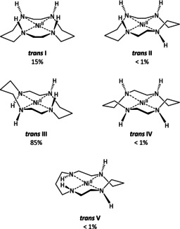
Configurational isomers of square‐planar [Ni(cyclam)]+ in solution and percentages of each present at equilibrium. Adapted with permission from ref. [286]. Copyright 1987 American Chemical Society.
The studies emphasized the tremendous influence of the electrode material because the reduced complex was generated at potentials almost 1.0 V more positive than the formal potential of the [Ni(cyclam)]2+/+ redox couple in solution. In 1998, Bujno et al. suggested as the major reason that the mercury surface is negatively charged at the applied potential of CO2 reduction and, upon binding of the catalyst, acts as a strong electron donor. [287] Furthermore, they argued that the active species needs to undergo isomerization from trans III to trans I prior to CO2 activation in accordance with computational studies by Sakaki. [288]
Additionally, the authors ruled out the formation of a Ni–H species by chronocoulometric measurements in the pH range between 1 and 10. Changes in the slope of the resulting plots—a characteristic feature when protons are involved—were not observed. Summarizing their findings, they proposed the reaction mechanism depicted in Scheme 32.
Scheme 32.
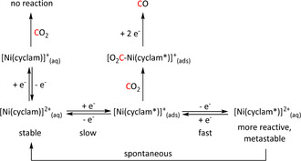
Reductive adsorption of [Ni(cyclam)]+, oxidative desorption, and possible connection with the catalytic reduction of CO2 at mercury electrodes in solutions of [Ni(cyclam)]+ proposed by Balazs et al. [285] (cyclam*=form of the coordinated ligand that produces the more easily reduced [Ni(cyclam*)]2+).
In a follow‐up study, Balazs et al. investigated the influence of CO on the catalytic behavior of [Ni(cyclam)]2+. [289] They found an insoluble species precipitating on the mercury electrode that significantly inhibited further CO2 reduction. Following their previous results and in accordance with the findings of Bujno et al., [290] they assigned the precipitate to the neutral one‐electron‐reduction product [Ni(cyclam)CO]0. This further supported their mechanistic suggestions and attributed CO2 reduction to CO via the ETM route.
Wu et al. conducted a computational study to corroborate the conformation of the catalyst species adsorbed on Hg with the poisoning of the catalyst by CO. [291] According to their results, the Hg surface favors the trans III conformer over trans I, which results in increased activity. Flattening of the ligand system on the electrode surface (by dispersive interactions) weakens the Ni–CO σ‐interactions and, hence, facilitates CO desorption, ultimately leading to less catalyst deactivation.
In an attempt to avoid Hg electrodes and make [Ni(cyclam)]2+ a “real” homogeneous catalyst, Kubiak's group added a second complex, [Ni(1,4,8,11‐tetramethyl‐1,4,8,11‐tetraazacyclotetradecane)]2+ ([Ni(TMC)]2+), as a CO scavenger. [Ni(TMC)]2+ exhibits a strong binding constant for CO of 1.2±0.4×10⁵, [292] but was previously found to be inactive in CO2 reduction and does not show waves in the CV that could interfere with [Ni(cyclam)]2+. The authors observed a tenfold increase in current when the CO scavenger was added and were also able to track the CO capture reaction using IR‐SEC. Moreover, they pointed out that the addition of [Ni(TMC)]2+ also prevents the formation of gaseous and toxic Ni(CO)4, which may occur by decomposition of Ni–cyclam species when excess CO is present at the electrode surface. In addition to improving activity, [Ni(TMC)]2+ thus also alleviates a severe safety hazard during the experiment.
Apart from the predominantly investigated CO product, the Sauvage group also reported HCO2H production with [Ni(cyclam)]2+ but, surprisingly, at less negative potentials (−1.4 V vs. SCE for max. HCO2 − FE compared to −1.6 V vs. SCE for max. CO FE). [54a] They suggest the catalytic cycle in Scheme 33, proposing a side‐on Ni–CO2 complex as the key intermediate. Depending on the applied potential, the C‐bound route towards CO and H2O or the O‐coordinated intermediate for HCO2 − formation are pursued. Computational studies by Song et al. are in line with these propositions; they found that the η1‐CO2 adduct is 14 kcal mol−1 lower in energy than the η1‐OCO species, explaining the favored formation of CO with [Ni(cyclam)]2+. [293]
Scheme 33.
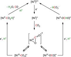
Mechanistic cycles for CO2 reduction by [Ni(cyclam)]2+ as proposed by Collin et al. Adapted with permission from ref. [54a]. Copyright 1988 American Chemical Society.
The Jäger and Zhang groups observed oxalate formation with double‐bond‐ and/or oxygen‐containing [Ni(cyclam)]2+ derivatives (Table 9, entries 2e and 2f).[ 54b , 294 ] In their study, Jäger and co‐workers investigated the mechanism for the formation of C2O4 2− in 98 % FE by CV‐based kinetic analysis experiments. Starting from the assumption that the mechanism traverses a radical anion, the crucial question to answer was whether the conversion occurs by outer‐sphere electron transfer or via an inner‐sphere metal‐bound CO2 intermediate. According to their results, the inner‐sphere ETM mechanism traversing a Ni–CO2 − intermediate is the favored pathway. Interestingly, they observed that the most active and stable ligands contain a carbonyl or ester group in the R2 position. On the one hand, the functionalities could promote electron transfer between catalyst and carbon dioxide. On the other hand, molecular orbital characterizations determined a significant negative charge at the R2 carbon atom of unsubstituted catalysts. Protection of these nucleophilic carbon atoms prevents the attack of electrophiles and, thus, increases the stability of the system. The experimental findings based on IR and UV/Vis spectroscopy in the Zhang group supported this mechanistic hypothesis. In the proposed reaction scheme, they showed dimerization of the carbon dioxide radical anions while still attached to the Ni catalyst. The oxalate subsequently precipitated from the solution by reaction with the Bu4N+ conducting salt (Scheme 34).
Scheme 34.
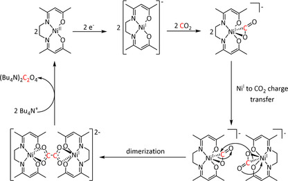
Electrocatalytic cycle for oxalate formation as proposed by the Zhang group. [54b]
Other reported Ni catalysts in Table 9 mainly exhibited good performance in CO production. A notable exception is the Ni–salen complex of Bose et al. modified with an NH2 group that yielded ethanol with ca. 35 % FE and methanol as well as acetaldehyde with 16 and 7 % FE, respectively, when immobilized on a graphite electrode. [295] The authors postulate a NiI species responsible for the activation of CO2, but further mechanistic evaluation is currently not available.
Palladium complexes used for electrocatalytic CO2 reduction mostly comprise ternary phosphine ligands (Table 10, entries 1a–e), CNC pincer‐type structures (Table 10, entry 2), and in few cases purely nitrogen‐based ligands (Table 10, entries 3, 4a, and 4b). The main products in the electrolysis are CO and H2, with efficiencies <95 %. Formate was reported only with rather low current yields of a maximum of 45 % (Table 10, entry 4a).
Table 10.
Catalytic systems, major products, maximum FEs, and mechanisms of Pd and Pt complexes in electrochemical CO2 reduction (n.a.=not available, prop.=proposal, comp.=computational investigation, exp.=experimental evidence).
|
Entry |
Cat. system |
Substitution |
Major product |
Max. FE (%) |
Mechanism |
Basis |
Method |
Ref. |
|---|---|---|---|---|---|---|---|---|
|
1a |
|
L=MeCN, PEt3, PPh3, P(CH2OH)3, P(OMe)3 R1=Et, neopentyl, Cy, Ph, (CH2)2PO(OEt)2, NMe2 R2=tBu, neopentyl, Ph, Mes, (CH2)3OH, TMB,[a] (CH2)2PMe3 +, (CH2)2PBu3 +, NMe2, NEt2, NiPr2, OMe |
CO/H2O CH4 H2 |
94 [319] 11 [319] 90 [316] |
ETH [320] ETM [316] |
prop. exp. |
n.a. CV |
[316, 319–321] |
|
|
|
|
|
|
|
|
|
|
|
1b |
|
R=Et, Ph |
CO/H2O H2 |
25 87 |
n.a. |
n.a. |
n.a. |
|
|
1c |
|
– |
CO/H2O H2 |
37 68 |
n.a. |
n.a. |
n.a. |
|
|
1d |
|
R=Et, Cy Y=CH2, 1,3‐phenyl |
CO/H2O H2 |
85 [323] 26 [324] |
ETM |
exp. |
CV |
|
|
1e |
|
l=2, 3; m=1, 2, 3; n=1, 2 R1=Et, Cy; R2=Ph, Mes X=H, MeCN |
CO/H2O H2 |
97 39 |
ETM |
prop. |
n.a. |
|
|
2 |
|
L=MeCN, Cl, Br; n=1, 2 R1=H, Br, OMe, CO2(CH2)4OH; R2=H R2∩R2=Ph, pyr, phenanthrene R3=Bu, CH2PyMe+, propylNMe3 +, propylPEt3 +, propylPPh3 +, CH2C6H4PPh3 + |
CO H2 |
52 [326] 100 [326] |
ETM |
comp. |
DFT |
[305, 317, 326, 327] |
|
3 |
[PdL2Cl2] |
L=pyrazole, 4‐methylpyridine, 3‐methylpyrazole |
HCO2 − H2 |
20 54 |
ETM |
prop. |
n.a. |
|
|
|
|
|
|
|
|
|
|
|
|
4a |
[Pd(PPh3)2L]+ |
R1= –, H, OH; R2= –, Me, OH; Y=C, N |
CO/H2O HCO2 − |
75 45 |
ETM |
prop. |
n.a. |
|
|
|
|
|
|
|
|
|
|
|
|
4b |
[Pd(PPh3)2L]2+ |
L=4,4′‐dimethyl‐2,2′‐bpy, 4‐methyl‐1,10‐phen |
CO/H2O HCO2 − |
81 40 |
ETM |
prop. |
n.a. |
|
|
|
|
|
|
|
|
|
|
|
|
5 |
[Pt(dmpe)2]2+ |
dmpe=1,2‐bis(dimethyl‐ phosphino)ethane |
HCO2 − |
90 [318] |
ETH |
exp. [329] |
CV, NMR |
[a] TMB=trimethoxybenzyl.
DuBois et al. investigated the mechanism for the Pd‐catalyzed CO2 reduction to CO, which is now widely accepted in the pertinent literature. [316] Among other techniques, they performed cyclic voltammetry measurements at various pH values to assess the kinetic parameters of the reaction cycle (Scheme 35). In conclusion, the ETM pathway was confirmed with PdI constituting the active species for CO2 activation.
Scheme 35.
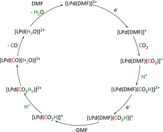
Catalytic cycle for CO2 electroreduction to CO using Pd catalyst systems as proposed by DuBois et al. (L=bis[(dicyclohexylphosphino)ethyl]phenylphosphine). Adapted with permission from ref. [316]. Copyright 1991 American Chemical Society.
A frequent side reaction resulting in catalyst deactivation is the dimerization of the PdI species after the first one‐electron reduction. The stable dimer in Figure 12 could be isolated and analyzed by NMR spectroscopy and X‐ray diffraction studies.
Figure 12.

Observed Pd dimer as a deactivation product in the study of DuBois et al. (R=Ph, R′=Et/Ph). [316]
Recently, DeLuca et al. investigated a tridentate N‐heterocyclic carbene containing ligand framework and focused on the effect of pendant phosphonium chains on the catalytic activity for the reduction of CO2 to CO (Table 10, entry 2). [317] Although the maximum FE obtained for CO was only 49 % when a tetraphenylphosphonium ion was incorporated into the ligand backbone, the authors identified a stabilization of the carboxyl group by the cation. Moreover, they proposed a stronger stabilization caused by the steric effect, since shielding of the reaction center blocks interfering solvent or electrolyte molecules. The higher hydrophobicity also holds off protons and, hence, prevents hydrogen evolution as a prominent side reaction.
Ceballos et al. presented an example of the homogeneous platinum‐catalyzed electroreduction of CO2. [318] The diphosphine‐coordinated catalyst yielded formate exclusively in 90 % Faradaic efficiency, most likely via the ETH pathway. The authors based this proposal on hydricity studies, according to which the employed catalyst performs in the sweet spot between too low hydricity for CO2 reduction and too high hydricity leading to H2 side production.
3.6. Groups 11 and 12: Cu, Zn
Apart from coordination compounds of transition metals from Groups 6 to 10, only very few further examples can be found in the literature. To the best of our knowledge, copper and zinc are the only metals for which molecular structures coordinated by CO2 have been reported and which are catalytically active in CO2 reduction. Unfortunately, the reported product compositions were quantified only for a small number of complexes. One such example is the copper dimer described by Angamuthu et al. (Table 11, entry 3). [58] The dicationic copper dimer [Cu]2+ forms an oxalate‐bridged tetramer [Cu]4+ after the reduction of four CO2 molecules (Scheme 36), which could be confirmed by X‐ray diffraction analysis and mass spectrometric methods. The measured cyclic voltammograms display an irreversible reduction peak at −0.03 V vs. NHE. CPE analysis revealed the reduction of the tetramer to the dimer at this potential with the liberation of the oxalate precipitating as a lithium salt (LiClO4 is used as the conductive salt). The authors reported a current efficiency of 96 %, but unfortunately, only six turnovers were obtained after seven hours.
Table 11.
Catalytic systems, major products, maximum FEs, and mechanisms of Cu and Zn complexes in electrochemical CO2 reduction (n.a.=not available, prop.=proposal, comp.=computational investigation, exp.=experimental evidence).
|
Entry |
Cat. system |
Substitution |
Major product |
Max. FE (%) |
Mechanism |
Basis |
Method |
Ref. |
|---|---|---|---|---|---|---|---|---|
|
1 |
CuCl2 + PPh3 (in situ) |
– |
CO HCO2H H2C2O4 |
73 (combined) |
n.a. |
n.a. |
n.a. |
|
|
2 |
|
L=MeCN, py R1=H, Me, tBu R2=iPr, Ph |
CO/CO3 2− |
n.a. |
ETM |
exp. [332] |
IL, IR‐SEC |
|
|
3 |
|
– |
C2O4 2− |
96 |
ETM |
exp. |
MS, XRD |
|
|
4 |
|
R=octyl, dodecyl |
n.a. |
n.a. |
n.a. |
n.a. |
n.a. |
|
|
5 |
|
– |
CO [335] CH4 [336] H2 [336] |
48 7 90 |
n.a. |
n.a. |
n.a. |
|
|
6 |
|
– |
CO HCO2H |
78 31 |
ETM |
exp. comp. |
IR‐SEC DFT |
|
|
7 |
|
– |
CO |
33 |
n.a. |
n.a. |
n.a. |
|
|
8 |
|
– |
CO |
n.a. |
ETM |
prop. |
n.a. |
Scheme 36.
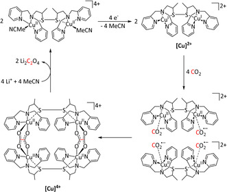
Electrocatalytic cycle for oxalate formation by a copper dimer as proposed by Angamuthu et al. [58]
The Group 12 transition metals provide even fewer examples of electrocatalysts for CO2 reduction, which exclusively rely on zinc metal centers. In 2016, Donnovan et al. subjected a bis‐pyridine complex with pendant PPh2 groups to CV analysis under a CO2 atmosphere and observed an increasing current at −1.66 V vs. Fc/Fc+ (Table 11, entry 8). [330] Quantitative data on the catalytic efficiency were not reported, however. The possibility of involvement of the phosphine substituents in the CO2 activation was discussed as presented in Scheme 37; however, high‐pressure 31P NMR spectroscopy under CO2 atmosphere did not show a shift attributable to a P–CO2 interaction.
Scheme 37.
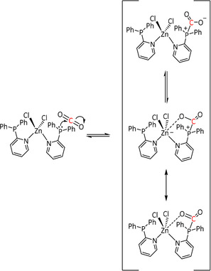
Assistance of pendant PPh2 groups in CO2 activation by Zn bis‐pyridine complexes as proposed by Donovan et al. [330]
4. Perspective: Using Organometallic Electrocatalysis to Achieve Molecular Diversity
With the rapidly growing number of transition metal complex catalysts that are in principle able to mediate the electron transfer to CO2, it would seem conceivable to explore this strategy also for the formation of more sophisticated and higher value products beyond CO and formate. While a broad range of synthetic methodologies combining CO2/H2 as synthons with other substrates to generate various functional groups have been established recently,[ 35b , 35c , 338 ] corresponding efforts in electrocatalysis have been addressed in only a piecemeal way. This may be partly due to a conceptual focus on storage systems for fluctuating energy supply. However, the urgent need for production methods to establish sustainable value‐added chains for existing and future products in chemistry creates a strong application‐oriented pull for basic catalysis research. [17] Expanding the potential of electrocatalytic CO2 reduction towards the molecular diversity of the products seems to hold great promise in this context. The present review may help to catalyze this development by further converging the fields of electrocatalysis and organometallic (homogeneous) catalysis based on a common understanding of the molecular mechanisms involved.
One obvious way for the expansion of the product variety follows the C1 pathway of Figure 3, leading to the higher reduced molecules formaldehyde, methanol, and methane. Repeated hydride transfer to the C=O units of the intermediates provides a potential mechanistic scenario for controlling the individual products along the reduction sequence in line with corresponding hydrogenation catalysts. [339] Consequently, the ETH mechanism appears as a preferred molecular path for the electrocatalytic synthesis of formaldehyde or methanol. While an a priori prediction of whether a given catalyst would follow the ETM or ETH pathway is currently not possible, certain trends can be deduced from the analysis of the formation of CO or HCO2H as a product. As a visual representation, the plots in Figure 13 provide an overview of the trends in product distribution for carbon monoxide and formate formation according to the position of the metal center of the involved molecular electrocatalyst in the periodic table of elements. Catalysts generating the two products are taken into account in both figures.
Figure 13.
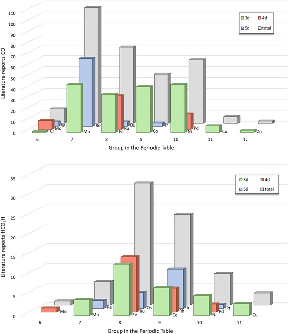
Indication of product formation by the number of literature reports for different transition metals. Top: Carbon monoxide; bottom: formic acid.
The plots show the favored production of CO, especially in Groups 7, 8, and 10 of the periodic table, mainly comprising the Mn‐, Re‐, and Ru‐bpy as well as Fe‐TPP and Ni‐cyclam architectures. The currently available mechanistic information indicates a prevalence of the ETM pathway for this group of catalysts. Concomitant with the lower number of examples for CO in Groups 8 and 9, an increasing number of reports for HCO2 −/HCO2H are found. It is noteworthy that the metals constituting well‐performing electrocatalysts in these groups (Ru, Rh, Ir) are also known to form highly efficient CO2 hydrogenation catalysts. Therefore, it is reasonable to conclude that the reactive hydride intermediates in both areas of CO2 reduction exhibit a favorable hydricity for formic acid or formate formation, pointing towards ETH as the main pathway. The hydricity, as previously reported for various catalytic systems in electro‐ or thermocatalytic CO2 reduction,[ 318 , 340 ] appears as a crucial factor in determining which of the reaction routes is pursued. Figure 13 indicates that hydricity not only decides whether HCO2H formation is favored over proton reduction or vice versa; it is even capable of shutting down the ETM mechanism in favor of the ETH route. Modulating the hydricity further by adjusting the electronic and geometric parameters of the ligand framework may thus be envisaged as a promising approach to develop electrocatalytic systems for formaldehyde or methanol production.
In order to map out the wide space below the C1 line shown in Figure 3, the reduction steps have to be combined with elementary steps leading to the bond formation with additional substrates. The ETM and ETH concept introduced in this review can be developed further and generalized into two basic mechanistic scenarios for electrocatalysis towards higher molecular complexity (Scheme 38):
Scheme 38.
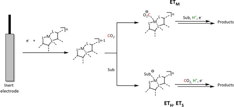
Possible pathways for electrochemically driven transition metal catalyzed coupling of substrates (Sub) with CO2 to generate products of higher molecular complexity.
Activation of CO2 and subsequent reaction with a (nucleophilic or electrophilic) substrate molecule (ETM)
Activation of a substrate molecule and subsequent attack of CO2 (ETH, ETS)
The first possibility involves the activation of CO2 through coordination and electron transfer and hence belongs to the general category of the ETM mechanism, following the upper trajectory in Scheme 38. The formation of C2 products (e.g., oxalate, ethanol, and ethylene) by reaction with a second activated or non‐activated CO2 molecule (Sub=CO2) falls under this approach. It is, however, currently described only for a very small fraction of catalysts presented in Section 3, which are, in most cases, immobilized on the electrode surface. Single examples involving heteroatom‐containing substrates such as the conducting salts are also found in Section 3. Transferring these insights from isolated observations to design might hold valuable opportunities for electrocatalytic synthesis.
Alternatively, the coordination and electron transfer to a substrate molecule may activate it for subsequent attack by CO2, as shown in the lower pathway of Scheme 38. In its simplest form, this is represented in the ETH mechanism, where Sub=H+. Rather than reacting with CO2, the metal hydride complex could react with another unsaturated molecule, such as an olefin, forming a reactive intermediate ready for CO2 insertion. Direct activation of substrates by the reduced metal complex is, of course, also conceivable. We propose to categorize both pathways that form such highly reactive substrate complexes as “electron transfer through substrate” (ETS) to distinguish them from direct hydride transfer.
A possible approach to pursuing these mechanisms is the electrocarboxylation reaction. Here, carbon dioxide is used to yield mono‐ or dicarboxylic acids from substrates such as olefins, alkyl/aryl halides, and ketones. Unfortunately, some severe drawbacks affect these reactions. Usually, the substrate molecule is reduced, yielding the radical anion as a nucleophile, which can then attack the carbon dioxide. [341] However, often the required potentials are more negative than those for the reduction of CO2 to CO2 .−, leading to subsequent dimer formation. [342] In the case of alkyl halides, additional esterification reactions between the carboxylate intermediate and residual halide substrate occur. [343] Moreover, if proton sources like water are present in the reaction environment, the production of formate is dominant. This means that for isolation of the carboxylates, other cation sources had to be found, which were often introduced by sacrificial anodes, leading to loss of material. [341] While the reaction can be performed purely electrochemically, iron, [344] cobalt, [345] nickel,[ 345d , 346 ] palladium, [347] and samarium [348] catalysts are known to enhance the selectivity (apart from dimerization of the aliphatic or aromatic residues from their respective halides). For example, the generation of carboxylic acids can be achieved by insertion of CO2 into the metal–substrate bond according to the ETS mechanism, as depicted in Scheme 39 in the case of the carboxylation of aryl halides catalyzed by [Ni(dppe)]. [346a]
Scheme 39.
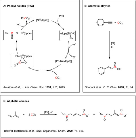
A) Selected examples for the transition metal catalyzed electrocarboxylation of phenyl halides, [346a] B) aromatic alkynes, [346d] and C) aliphatic alkenes. [344] .
Scheme 39 also shows examples of electrocatalytic carboxylation reactions with aromatic alkynes [346d] and aliphatic dienes[ 344 , 345d ] to highlight the already accessible substrate scope.
Based on these precedents, we propose that molecular complexity can be achieved by combining the elemental steps of homogeneous catalysis with the electrocatalytically driven reduction of the carbon dioxide building block during the reaction. We believe that pursuing the scientific goals arising from an increasingly unified mechanistic and conceptual thinking between the two disciplines constitutes a major challenge and opportunity for the transition from fossil to renewable resources, holding potential for technologies to deliver economic, ecologic, and social benefits to humankind.
We hope that this article will prove useful for (molecular) electrochemists who are already working in the area of carbon dioxide reduction and for those who enter into this exciting area. The structured compilation of data, its analytical discussion, and the proposed mechanistic concept were devised with the aim to provide the reader with motivation for future developments by combining both fundamental organometallic chemistry and electrochemistry. Finally, it would be most rewarding for us if the readers enjoy reading the review as much as we enjoyed conceiving it.
Appendix: Tables 1–11
Glossary
- η
overpotential/coordination mode
- ads
adsorbed
- bpy
2,2′‐bipyridine
- catox
oxidized catalyst species
- catred
reduced catalyst species
- Cy
cyclohexyl
- comp.
computational investigation
- Cp
cyclopentadiene
- Cp*
pentamethylcyclopentadiene
- CPE
controlled potential electrolysis
- CPET
concerted proton–electron transfer
- CV
cyclic voltammetry
- cyclam
1,4,8,11‐tetraazacyclotetradecane
- DFT
density functional theory
- diphos, dppe
1,2‐bis(diphenylphosphino)ethane
- DMF
N,N‐dimethylformamide
- dmpe
1,2‐bis(dimethylphosphino)ethane
- dmphen
2,9‐dimethyl‐1,10‐phenanthroline
- E
electrode potential
- Ecat
potential of catalyst reduction
- EPR
electron paramagnetic resonance
- Eonset
onset potential of CO2 reduction in an electrochemical experiment
- ET
electron transfer
- ETH
electron transfer through hydride
- Ethermo
thermodynamic potential of CO2 reduction
- ETM
electron transfer through molecular complex
- ETS
electron transfer through substrate
- exp.
experimental evidence
- Fc/Fc+
ferrocene/ferrocenium
- FE
Faradaic efficiency
- GC
gas chromatography
- HA
Brønsted acid
- IL
isotopic labeling
- Im
imidazol
- IR
infrared
- L
ligand
- LA
Lewis acid
- m
stoichiometry of coordinated ligands
- M
metal
- Mes
mesitylene
- MS
mass spectrometry
- MWCNT
multiwalled carbon nanotube
- n
formal oxidation state/charge of the metal
- n.a.
not available
- napy
1,8‐naphtyridine
- NHE
normal hydrogen electrode
- NMR
nuclear magnetic resonance
- pbn
2‐(pyridin‐2‐yl)benzo[b][1,5]naphthyridine
- Pc
phthalocyanine
- PCET
proton‐coupled electron transfer
- PEG
polyethylene glycol
- phen
phenanthroline
- PMI
pyridyl monoimine
- prop.
proposal
- PR
pulse radiolysis
- PSCAS
potential‐step chronoamperospectroscopy
- PT
proton transfer
- PVP
poly(4‐vinylpyridine)
- py
pyridine
- pyr
pyrene
- qui
quinoline
- salen
bis(salicylidene)ethylenediamine
- SCE
saturated calomel electrode
- SEC
spectroelectrochemistry
- SHE
standard hydrogen electrode
- SPET
sequential proton–electron transfer
- Sub
substrate
- tf
triflyl
- TFE
2,2,2‐trifluoroethanol
- TMC
1,4,8,11‐tetramethyl‐1,4,8,11‐tetraazacyclotetradecane
- TOF
turnover frequency
- TON
turnover number
- TPEN
N,N,N′,N′‐tetrakis(2‐pyridylmethyl)ethylenediamine
- TPP
tetraphenyl porphyrin
- tpy
terpyridine
- tr
triazole
- UHPLC
ultrahigh‐pressure liquid chromatography
- UV/Vis
ultraviolet/visible
- VSFG
vibration sum frequency generation
- XRD
X‐ray diffraction
Conflict of interest
The authors declare no conflict of interest.
Biographical Information
Niklas W. Kinzel studied chemistry at RWTH Aachen University, where he received his B.Sc. in Chemistry in 2015. After a research stay in industry during his Master's studies, he joined the group of Prof. Walter Leitner at the RWTH Aachen University to obtain a M.Sc. in Chemistry in 2018. Subsequently, he started his Ph.D. at the Max Planck Institute for Chemical Energy Conversion in the department of Molecular Catalysis (2018–present), where he is focusing on the electrocatalytic reduction of CO2 mediated by transition metal complexes.

Biographical Information
Christophe Werlé is a Max Planck Research Group Leader at the Max Planck Institute for Chemical Energy Conversion, working in collaboration with the Ruhr University Bochum. He leads the independent Max Planck Research Group of Synergistic Organometallic Catalysis. He obtained his doctoral degree from the University of Strasbourg in 2014. He conducted postdoctoral research first in the group of Prof. Dr. Alois Fürstner (2014–2016) and then in the group of Prof. Dr. Karsten Meyer (2016–2017). He served in the department of Molecular Catalysis of Prof. Dr. Walter Leitner as Group Leader of Organometallic Electrocatalysis (2017–2019) before starting his independent career in September 2019.

Biographical Information
Walter Leitner is Director at the Max Planck Institute for Chemical Energy Conversion in Mülheim an der Ruhr and holds the Chair of Technische Chemie und Petrolchemie at RWTH Aachen University. He is also Scientific Director of CAT, the joint Catalytic Center of RWTH Aachen and the company Covestro. His research focusses on a molecular approach to catalysis motivated by the principles of green chemistry. From 2004–2016, he served first as Scientific Editor and later as Chairman of the Editorial Board of the Journal “Green Chemistry”, published by the Royal Society of Chemistry (UK) and since 2018 he is a member of the Editorial Board of “Angewandte Chemie”.

Acknowledgements
We gratefully acknowledge basic support by the Max Planck Society, the RWTH Aachen University, and the Ruhr University Bochum. The work was supported by the Deutsche Forschungsgemeinschaft (DFG, German Research Foundation) under Germany's Excellence Strategy—Exzellenzcluster 2186 “The Fuel Science Center” (ID: 390919832) and the Kopernikus Project P2X: Flexible use of renewable resources—exploration, validation, and implementation of “Power‐to‐X” concepts (FKZ: 03SFK2A0‐2) funded by the German Federal Ministry of Education and Research (BMBF). We thank Dr. Nicolas Kaeffer for useful discussions and comments on the manuscript. Open Access funding is provided by the Max Planck Society. Open access funding enabled and organized by Projekt DEAL.
N. W. Kinzel, C. Werlé, W. Leitner, Angew. Chem. Int. Ed. 2021, 60, 11628.
Contributor Information
Dr. Christophe Werlé, Email: christophe.werle@cec.mpg.de.
Prof. Dr. Walter Leitner, Email: walter.leitner@cec.mpg.de.
References
- 1.S. Solomon, D. Qin, M. Manning, Z. Chen, M. Marquis, K. B. Averyt, M. Tignor, H. L. Miller in Climate Change 2007: The Physical Science Basis. Contribution of Working Group I to the Fourth Assessment Report of the Intergovernmental Panel on Climate Change, IPCC, Cambridge, United Kingdom and New York, NY, USA, 2007.
- 2. Schmalensee R., Stoker T. M., Judson R. A., Rev. Econ. Stat. 1998, 80, 15. [Google Scholar]
- 3. Woods J., Williams A., Hughes J. K., Black M., Murphy R., Philos. Trans. R. Soc. London Ser. B 2010, 365, 2991. [DOI] [PMC free article] [PubMed] [Google Scholar]
- 4.
- 4a. Lee D. S., Fahey D. W., Forster P. M., Newton P. J., Wit R. C. N., Lim L. L., Owen B., Sausen R., Atmos. Environ. 2009, 43, 3520; [DOI] [PMC free article] [PubMed] [Google Scholar]
- 4b. Eyring V., Isaksen I. S. A., Berntsen T., Collins W. J., Corbett J. J., Endresen O., Grainger R. G., Moldanova J., Schlager H., Stevenson D. S., Atmos. Environ. 2010, 44, 4735; [Google Scholar]
- 4c. Lee D. S., Pitari G., Grewe V., Gierens K., Penner J. E., Petzold A., Prather M. J., Schumann U., Bais A., Berntsen T., Iachetti D., Lim L. L., Sausen R., Atmos. Environ. 2010, 44, 4678; [DOI] [PMC free article] [PubMed] [Google Scholar]
- 4d. Uherek E., Halenka T., Borken-Kleefeld J., Balkanski Y., Berntsen T., Borrego C., Gauss M., Hoor P., Juda-Rezler K., Lelieveld J., Melas D., Rypdal K., Schmid S., Atmos. Environ. 2010, 44, 4772; [Google Scholar]
- 4e. Howitt O. J. A., Carruthers M. A., Smith I. J., Rodger C. J., Atmos. Environ. 2011, 45, 7036; [Google Scholar]
- 4f. Masiol M., Harrison R. M., Atmos. Environ. 2014, 95, 409. [DOI] [PMC free article] [PubMed] [Google Scholar]
- 5. Worrell E., Price L., Martin N., Hendriks C., Meida L. O., Annu. Rev. Energy Environ. 2001, 26, 303. [Google Scholar]
- 6. Levi P. G., Cullen J. M., Environ. Sci. Technol. 2018, 52, 1725. [DOI] [PubMed] [Google Scholar]
- 7.
- 7a. Keeling C. D., Whorf T. P., Wahlen M., van der Plichtt J., Nature 1995, 375, 666; [Google Scholar]
- 7b. Petit J. R., Jouzel J., Raynaud D., Barkov N. I., Barnola J. M., Basile I., Bender M., Chappellaz J., Davis M., Delaygue G., Delmotte M., Kotlyakov V. M., Legrand M., Lipenkov V. Y., Lorius C., Pépin L., Ritz C., Saltzman E., Stievenard M., Nature 1999, 399, 429; [Google Scholar]
- 7c. Shakun J. D., Clark P. U., He F., Marcott S. A., Mix A. C., Liu Z., Otto-Bliesner B., Schmittner A., Bard E., Nature 2012, 484, 49. [DOI] [PubMed] [Google Scholar]
- 8.P. Tans, R. Keeling, “Trends in Atmospheric Carbon Dioxide”, can be found under https://www.esrl.noaa.gov/gmd/ccgg/trends/mlo.html, 2020.
- 9.
- 9a. Wang M., Lawal A., Stephenson P., Sidders J., Ramshaw C., Chem. Eng. Res. Des. 2011, 89, 1609; [Google Scholar]
- 9b. Monastersky R., Nature 2013, 497, 13. [DOI] [PubMed] [Google Scholar]
- 10. Bhanage B. M. in Transformation and Utilization of Carbon Dioxide, Springer, Berlin, Heidelberg, 2014. [Google Scholar]
- 11. Werlé C., Meyer K., Organometallics 2019, 38, 1181. [Google Scholar]
- 12.
- 12a. Meyer T. J., Acc. Chem. Res. 1989, 22, 163; [Google Scholar]
- 12b. Alstrum-Acevedo J. H., Brennaman M. K., Meyer T. J., Inorg. Chem. 2005, 44, 6802; [DOI] [PubMed] [Google Scholar]
- 12c.D. King, J. Browne, R. Layard, G. O'Donnell, M. Rees, N. Stern, A. Turner, A Global Apollo Programme to Combat Climate Change, London School of Economics and Science, 2015;
- 12d. Brinkert K., in Energy Conversion in Natural and Artificial Photosynthesis, Springer International Publishing, Cham, 2018. [Google Scholar]
- 13.
- 13a. Benson E. E., Kubiak C. P., Sathrum A. J., Smieja J. M., Chem. Soc. Rev. 2009, 38, 89; [DOI] [PubMed] [Google Scholar]
- 13b. Inglis J. L., MacLean B. J., Pryce M. T., Vos J. G., Coord. Chem. Rev. 2012, 256, 2571. [Google Scholar]
- 14. von der Assen N., Müller L. J., Steingrube A., Voll P., Bardow A., Environ. Sci. Technol. 2016, 50, 1093. [DOI] [PubMed] [Google Scholar]
- 15. Vol′pin M. E., Kolomnikov I. S., Pure Appl. Chem. 1973, 33, 567. [Google Scholar]
- 16.
- 16a. Aresta M., Dibenedetto A., Dalton Trans. 2007, 2975; [DOI] [PubMed] [Google Scholar]
- 16b. Aresta M., Dibenedetto A., Angelini A., Chem. Rev. 2014, 114, 1709; [DOI] [PubMed] [Google Scholar]
- 16c. Nielsen D. U., Hu X.-M., Daasbjerg K., Skrydstrup T., Nat. Catal. 2018, 1, 244. [Google Scholar]
- 17. Zimmerman J. B., Anastas P. T., Erythropel H. C., Leitner W., Science 2020, 367, 397. [DOI] [PubMed] [Google Scholar]
- 18. Perathoner S., Centi G., ChemSusChem 2014, 7, 1274. [DOI] [PubMed] [Google Scholar]
- 19.
- 19a. Offermanns H., Effenberger F. X., Keim W., Plass L., Chem. Ing. Tech. 2017, 89, 270; [Google Scholar]
- 19b.K. Wagemann, F. Ausfelder, E-Fuels—Mehr als eine Option, 2017.
- 20.The source of the figure is distributed under the Creative Commons Attribution 4.0 License. Kaspar F., Borsche M., Pfeifroth U., Trentmann J., Drücke J., Becker P., Adv. Sci. Res. 2019, 16, 119. [Google Scholar]
- 21.
- 21a. Faraday M., Ann. Phys. 1834, 109, 433; [Google Scholar]
- 21b. Lund H., J. Electrochem. Soc. 2002, 149, S21. [Google Scholar]
- 22. Kolbe H., J. Prakt. Chem. 1847, 41, 137. [Google Scholar]
- 23. Tafel J., Hahl H., Ber. Dtsch. Chem. Ges. 1907, 40, 3312. [Google Scholar]
- 24. Kingston C., Palkowitz M. D., Takahira Y., Vantourout J. C., Peters B. K., Kawamata Y., Baran P. S., Acc. Chem. Res. 2020, 53, 72. [DOI] [PMC free article] [PubMed] [Google Scholar]
- 25. O'Brien T. F., Bommoraju T. V., Hine F. in Handbook of Chlor-Alkali Technology, Springer, Dordecht, Netherlands, 2005. [Google Scholar]
- 26. Hawecker J., Lehn J.-M., Ziessel R., J. Chem. Soc. Chem. Commun. 1984, 328. [Google Scholar]
- 27.
- 27a. Baizer M. M., J. Electrochem. Soc. 1964, 111, 215; [Google Scholar]
- 27b. Baizer M. M., Tetrahedron Lett. 1963, 4, 973; [Google Scholar]
- 27c. Baizer M. M., Ann. N. Y. Acad. Sci. 1969, 147, 614; [Google Scholar]
- 27d. Kado Y., in Encyclopedia of Applied Electrochemistry (Hrsg.: Kreysa G., Ota K.-i., Savinell R. F.), Springer, New York, NY, 2014, pp. 153. [Google Scholar]
- 28.
- 28a. Moeller K. D., Tetrahedron 2000, 56, 9527; [Google Scholar]
- 28b. Sperry J. B., Wright D. L., Chem. Soc. Rev. 2006, 35, 605; [DOI] [PubMed] [Google Scholar]
- 28c. Yoshida J., Kataoka K., Horcajada R., Nagaki A., Chem. Rev. 2008, 108, 2265; [DOI] [PubMed] [Google Scholar]
- 28d. Ogibin Y. N., Elinson M. N., Nikishin G. I., Russ. Chem. Rev. 2009, 78, 89; [Google Scholar]
- 28e. Sequeira C. A. C., Santos D. M. F., J. Braz. Chem. Soc. 2009, 20, 387; [Google Scholar]
- 28f. Horn E. J., Rosen B. R., Baran P. S., ACS Cent. Sci. 2016, 2, 302; [DOI] [PMC free article] [PubMed] [Google Scholar]
- 28g. Horn E. J., Rosen B. R., Chen Y., Tang J., Chen K., Eastgate M. D., Baran P. S., Nature 2016, 533, 77; [DOI] [PMC free article] [PubMed] [Google Scholar]
- 28h. Saveant J. M., Chemelectrochem 2016, 3, 1967; [Google Scholar]
- 28i. Kawamata Y., Yan M., Liu Z., Bao D. H., Chen J., Starr J. T., Baran P. S., J. Am. Chem. Soc. 2017, 139, 7448; [DOI] [PMC free article] [PubMed] [Google Scholar]
- 28j. Yan M., Kawamata Y., Baran P. S., Chem. Rev. 2017, 117, 13230; [DOI] [PMC free article] [PubMed] [Google Scholar]
- 28k. Möhle S., Zirbes M., Rodrigo E., Gieshoff T., Wiebe A., Waldvogel S. R., Angew. Chem. Int. Ed. 2018, 57, 6018; [DOI] [PMC free article] [PubMed] [Google Scholar]; Angew. Chem. 2018, 130, 6124; [Google Scholar]
- 28l. Wiebe A., Gieshoff T., Mohle S., Rodrigo E., Zirbes M., Waldvogel S. R., Angew. Chem. Int. Ed. 2018, 57, 5594; [DOI] [PMC free article] [PubMed] [Google Scholar]; Angew. Chem. 2018, 130, 5694; [Google Scholar]
- 28m. Yan M., Kawamata Y., Baran P. S., Angew. Chem. Int. Ed. 2018, 57, 4149; [DOI] [PMC free article] [PubMed] [Google Scholar]; Angew. Chem. 2018, 130, 4219. [Google Scholar]
- 29.
- 29a. Kolomnikov I. S., Grigoryan M. K., Russ. Chem. Rev. 1978, 47, 334; [Google Scholar]
- 29b. Aresta M. in Carbon Dioxide as a Source of Carbon Biochemical and Chemical Uses, Springer Netherlands, Dordrecht, 1987; [Google Scholar]
- 29c. Collin J. P., Sauvage J. P., Coord. Chem. Rev. 1989, 93, 245. [Google Scholar]
- 30.
- 30a.Novomer Inc., “Novomer Catalytic Process Using Waste CO2 and Shale Gas Targets $20 Billion Market and Up to 110 % Carbon Footprint Reduction Content”, can be found under https://www.novomer.com/novomer-catalytic-process-using-waste-co2-and-shale-gas-targets-20-billion-market-and-110-carbon, 2013;
- 30b.A. M. Bazzanella, F. Ausfelder, Low carbon energy and feedstock for the European chemical industry, DECHEMA Gesellschaft für Chemische Technik und Biotechnologie e.V., 2017;
- 30c.Covestro AG, “cardyonTM: brighter use of CO2”, can be found under https://www.covestro.com/en/cardyon/media, 2017;
- 30d.Econic Technologies Ltd, “How It Works”, can be found under http://econic-technologies.com/how-it-works/, 2017;
- 30e.Evonik Industries AG, “Evonik and Siemens to generate high-value specialty chemicals from carbon dioxide and eco-electricity”, can be found under https://corporate.evonik.com/en/pages/article.aspx?articleId=106259, 2018;
- 30f.Carbon Recycling International Ltd., “The Emissions-to-Liquids Technology”, can be found under https://www.carbonrecycling.is/technology-and-services, 2019;
- 30g. Krause R., Reinisch D., Reller C., Eckert H., Hartmann D., Taroata D., Wiesner-Fleischer K., Bulan A., Lueken A., Schmid G., Chem. Ing. Tech. 2020, 92, 53; [Google Scholar]
- 30h. Lee M.-Y., Park K. T., Lee W., Lim H., Kwon Y., Kang S., Crit. Rev. Environ. Sci. Technol. 2020, 50, 769. [Google Scholar]
- 31. Song C., Catal. Today 2006, 115, 2. [Google Scholar]
- 32.
- 32a. Palmer D. A., Vaneldik R., Chem. Rev. 1983, 83, 651; [Google Scholar]
- 32b. Lu X.-B. in Carbon Dioxide and Organometallics, Springer International Publishing, Cham, 2016. [Google Scholar]
- 33. Artz J., Mueller T. E., Thenert K., Kleinekorte J., Meys R., Sternberg A., Bardow A., Leitner W., Chem. Rev. 2018, 118, 434. [DOI] [PubMed] [Google Scholar]
- 34. Santos D. M. F., Sequeira C. A. C., Figueiredo J. L., Quím. Nov. 2013, 36, 1176. [Google Scholar]
- 35.
- 35a. Das Neves Gomes C., Jacquet O., Villiers C., Thuéry P., Ephritikhine M., Cantat T., Angew. Chem. Int. Ed. 2012, 51, 187; [DOI] [PubMed] [Google Scholar]; Angew. Chem. 2012, 124, 191; [Google Scholar]
- 35b. Liu Q., Wu L., Jackstell R., Beller M., Nat. Commun. 2015, 6, 5933; [DOI] [PubMed] [Google Scholar]
- 35c. Klankermayer J., Wesselbaum S., Beydoun K., Leitner W., Angew. Chem. Int. Ed. 2016, 55, 7296; [DOI] [PubMed] [Google Scholar]; Angew. Chem. 2016, 128, 7416. [Google Scholar]
- 36.
- 36a. Wang W., Wang S., Ma X., Gong J., Chem. Soc. Rev. 2011, 40, 3703; [DOI] [PubMed] [Google Scholar]
- 36b. Wang W. H., Himeda Y., Muckerman J. T., Manbeck G. F., Fujita E., Chem. Rev. 2015, 115, 12936. [DOI] [PubMed] [Google Scholar]
- 37. Jiang C., Nichols A. W., Machan C. W., Dalton Trans. 2019, 48, 9454. [DOI] [PubMed] [Google Scholar]
- 38.
- 38a. Bard A. J., Faulkner L. R. in Electrochemical Methods , 2nd ed., Wiley, New York, 2001; [Google Scholar]
- 38b. Appel A. M., Helm M. L., ACS Catal. 2014, 4, 630. [Google Scholar]
- 39. Francke R., Schille B., Roemelt M., Chem. Rev. 2018, 118, 4631. [DOI] [PubMed] [Google Scholar]
- 40. Qiao J., Liu Y., Hong F., Zhang J., Chem. Soc. Rev. 2014, 43, 631. [DOI] [PubMed] [Google Scholar]
- 41.
- 41a. Chen P., Fryling M. A., McCreery R. L., Anal. Chem. 1995, 67, 3115; [Google Scholar]
- 41b. Barbara P. F., Meyer T. J., Ratner M. A., J. Phys. Chem. 1996, 100, 13148; [Google Scholar]
- 41c. Bohra D., Chaudhry J. H., Burdyny T., Pidko E. A., Smith W. A., Energy Environ. Sci. 2019, 12, 3380. [Google Scholar]
- 42. Savéant J.-M., Chem. Rev. 2008, 108, 2348. [DOI] [PubMed] [Google Scholar]
- 43. Rosokha S. V., Kochi J. K., J. Am. Chem. Soc. 2007, 129, 3683. [DOI] [PubMed] [Google Scholar]
- 44. Costentin C., Robert M., Savéant J. M., Chem. Soc. Rev. 2013, 42, 2423. [DOI] [PubMed] [Google Scholar]
- 45.
- 45a. Pacansky J., Wahlgren U., Bagus P. S., J. Chem. Phys. 1975, 62, 2740; [Google Scholar]
- 45b. Gutsev G. L., Bartlett R. J., Compton R. N., J. Chem. Phys. 1998, 108, 6756; [Google Scholar]
- 45c. Bonifačić M., Hug G. L., Schöneich C., J. Phys. Chem. A 2000, 104, 1240. [Google Scholar]
- 46. Leitner W., Coord. Chem. Rev. 1996, 153, 257. [Google Scholar]
- 47.
- 47a. Noyori R., Ohkuma T., Angew. Chem. Int. Ed. 2001, 40, 40; [PubMed] [Google Scholar]; Angew. Chem. 2001, 113, 40; [Google Scholar]
- 47b. Noyori R., Angew. Chem. Int. Ed. 2002, 41, 2008; [PubMed] [Google Scholar]; Angew. Chem. 2002, 114, 2108; [Google Scholar]
- 47c. Sandoval C. A., Ohkuma T., Muñiz K., Noyori R., J. Am. Chem. Soc. 2003, 125, 13490. [DOI] [PubMed] [Google Scholar]
- 48. Gao G., Li F., Xu L., Liu X., Yang Y., J. Am. Chem. Soc. 2008, 130, 10838. [DOI] [PubMed] [Google Scholar]
- 49.
- 49a. Kaim W., Inorg. Chem. 2011, 50, 9752; [DOI] [PubMed] [Google Scholar]
- 49b. Kaim W., Eur. J. Inorg. Chem. 2012, 343; [Google Scholar]
- 49c. Grice K. A., Saucedo C., Inorg. Chem. 2016, 55, 6240; [DOI] [PubMed] [Google Scholar]
- 49d. Elgrishi N., Chambers M. B., Wang X., Fontecave M., Chem. Soc. Rev. 2017, 46, 761. [DOI] [PubMed] [Google Scholar]
- 50. Benson E. E., Sampson M. D., Grice K. A., Smieja J. M., Froehlich J. D., Friebel D., Keith J. A., Carter E. A., Nilsson A., Kubiak C. P., Angew. Chem. Int. Ed. 2013, 52, 4841; [DOI] [PubMed] [Google Scholar]; Angew. Chem. 2013, 125, 4941. [Google Scholar]
- 51.
- 51a. Filardo G., Gambino S., Silvestri G., Gennaro A., Vianello E., J. Electroanal. Chem. 1984, 177, 303; [Google Scholar]
- 51b. Seshadri G., Lin C., Bocarsly A. B., J. Electroanal. Chem. 1994, 372, 145; [Google Scholar]
- 51c. Gennaro A., Isse A. A., Savéant J.-M., Severin M.-G., Vianello E., J. Am. Chem. Soc. 1996, 118, 7190; [Google Scholar]
- 51d. Barton Cole E., Lakkaraju P. S., Rampulla D. M., Morris A. J., Abelev E., Bocarsly A. B., J. Am. Chem. Soc. 2010, 132, 11539; [DOI] [PubMed] [Google Scholar]
- 51e. Morris A. J., McGibbon R. T., Bocarsly A. B., ChemSusChem 2011, 4, 191; [DOI] [PubMed] [Google Scholar]
- 51f. Rosen B. A., Salehi-Khojin A., Thorson M. R., Zhu W., Whipple D. T., Kenis P. J. A., Masel R. I., Science 2011, 334, 643; [DOI] [PubMed] [Google Scholar]
- 51g. Keith J. A., Carter E. A., J. Am. Chem. Soc. 2012, 134, 7580; [DOI] [PubMed] [Google Scholar]
- 51h. Keith J. A., Carter E. A., J. Chem. Theory Comput. 2012, 8, 3187; [DOI] [PubMed] [Google Scholar]
- 51i. Ertem M. Z., Konezny S. J., Araujo C. M., Batista V. S., J. Phys. Chem. Lett. 2013, 4, 745; [DOI] [PubMed] [Google Scholar]
- 51j. Keith J. A., Carter E. A., Chem. Sci. 2013, 4, 1490; [Google Scholar]
- 51k. Yan Y., Zeitler E. L., Gu J., Hu Y., Bocarsly A. B., J. Am. Chem. Soc. 2013, 135, 14020; [DOI] [PubMed] [Google Scholar]
- 51l. Portenkirchner E., Enengl C., Eneng L. S., Hinterberger G., Schlager S., Apaydin D., Neugebauer H., Knör G., Sariciftci N. S., ChemElectroChem 2014, 1, 1543; [Google Scholar]
- 51m. Yan Y., Gu J., Bocarsly A., Aerosol Air Qual. Res. 2014, 14, 515; [Google Scholar]
- 51n. Lucio A. J., Shaw S. K., J. Phys. Chem. C 2015, 119, 12523; [Google Scholar]
- 51o. Parajuli R., Gerken J. B., Keyshar K., Sullivan I., Sivasankar N., Teamey K., Stahl S. S., Cole E. B., Top. Catal. 2015, 58, 57; [Google Scholar]
- 51p. Rybchenko S. I., Touhami D., Wadhawan J. D., Haywood S. K., ChemSusChem 2016, 9, 1660; [DOI] [PubMed] [Google Scholar]
- 51q. Zhao S.-F., Horne M., Bond A. M., Zhang J., J. Phys. Chem. C 2016, 120, 23989. [Google Scholar]
- 52.
- 52a. Castro-Rodriguez I., Nakai H., Zakharov L. N., Rheingold A. L., Meyer K., Science 2004, 305, 1757; [DOI] [PubMed] [Google Scholar]
- 52b. Aresta M., Dibenedetto A., Quaranta E. in Reaction mechanisms in carbon dioxide conversion, Springer, Berlin, Heidelberg, 2015; [Google Scholar]
- 52c. Paparo A., Okuda J., Coord. Chem. Rev. 2017, 334, 136. [Google Scholar]
- 53. Aresta M., Gobetto R., Quaranta E., Tommasi I., Inorg. Chem. 1992, 31, 4286. [Google Scholar]
- 54.
- 54a. Collin J. P., Jouaiti A., Sauvage J. P., Inorg. Chem. 1988, 27, 1986; [Google Scholar]
- 54b. Udugala-Ganehenege M. Y., Dissanayake N. M., Liu Y., Bond A. M., Zhang J., Transition Met. Chem. 2014, 39, 819. [Google Scholar]
- 55. Paparo A., Silvia J. S., Kefalidis C. E., Spaniol T. P., Maron L., Okuda J., Cummins C. C., Angew. Chem. Int. Ed. 2015, 54, 9115; [DOI] [PubMed] [Google Scholar]; Angew. Chem. 2015, 127, 9243. [Google Scholar]
- 56. Castro L., Lam O. P., Bart S. C., Meyer K., Maron L., Organometallics 2010, 29, 5504. [Google Scholar]
- 57.
- 57a. Bottomley F., Lin I. J. B., White P. S., J. Organomet. Chem. 1981, 212, 341; [Google Scholar]
- 57b. Castro L., Labouille S., Kindra D. R., Ziller J. W., Nief F., Evans W. J., Maron L., Chem. Eur. J. 2012, 18, 7886; [DOI] [PubMed] [Google Scholar]
- 57c. Schmidt A.-C., Heinemann F. W., Kefalidis C. E., Maron L., Roesky P. W., Meyer K., Chem. Eur. J. 2014, 20, 13501; [DOI] [PubMed] [Google Scholar]
- 57d. Tsoureas N., Castro L., Kilpatrick A. F. R., Cloke F. G. N., Maron L., Chem. Sci. 2014, 5, 3777. [Google Scholar]
- 58. Angamuthu R., Byers P., Lutz M., Spek A. L., Bouwman E., Science 2010, 327, 313. [DOI] [PubMed] [Google Scholar]
- 59. Chen L., Guo Z., Wei X.-G., Gallenkamp C., Bonin J., Anxolabéhère-Mallart E., Lau K.-C., Lau T.-C., Robert M., J. Am. Chem. Soc. 2015, 137, 10918. [DOI] [PubMed] [Google Scholar]
- 60.
- 60a. Riplinger C., Carter E. A., ACS Catal. 2015, 5, 900; [Google Scholar]
- 60b. Takeda H., Cometto C., Ishitani O., Robert M., ACS Catal. 2017, 7, 70. [Google Scholar]
- 61. McCarthy B. D., Martin D. J., Rountree E. S., Ullman A. C., Dempsey J. L., Inorg. Chem. 2014, 53, 8350. [DOI] [PubMed] [Google Scholar]
- 62.
- 62a. Franco F., Cometto C., Ferrero Vallana F., Sordello F., Priola E., Minero C., Nervi C., Gobetto R., Chem. Commun. 2014, 50, 14670; [DOI] [PubMed] [Google Scholar]
- 62b. Neri G., Aldous I. M., Walsh J. J., Hardwick L. J., Cowan A. J., Chem. Sci. 2016, 7, 1521. [DOI] [PMC free article] [PubMed] [Google Scholar]
- 63. Riplinger C., Sampson M. D., Ritzmann A. M., Kubiak C. P., Carter E. A., J. Am. Chem. Soc. 2014, 136, 16285. [DOI] [PubMed] [Google Scholar]
- 64. Sampson M. D., Kubiak C. P., J. Am. Chem. Soc. 2016, 138, 1386. [DOI] [PubMed] [Google Scholar]
- 65.
- 65a. Kothandaraman J., Goeppert A., Czaun M., Olah G. A., Prakash G. K. S., J. Am. Chem. Soc. 2016, 138, 778; [DOI] [PubMed] [Google Scholar]
- 65b. Zhang P., Ni S.-F., Dang L., Chem. Asian J. 2016, 11, 2528; [DOI] [PubMed] [Google Scholar]
- 65c. Wang W.-H., Feng X., Bao M., in Transformation of Carbon Dioxide to Formic Acid and Methanol, Springer, Singapore, 2018, p. 53; [Google Scholar]
- 65d. Barlow J. M., Yang J. Y., ACS Cent. Sci. 2019, 5, 580; [DOI] [PMC free article] [PubMed] [Google Scholar]
- 65e. Estes D. P., Leutzsch M., Schubert L., Bordet A., Leitner W., ACS Catal. 2020, 10, 2990. [Google Scholar]
- 66. Waldie K. M., Brunner F. M., Kubiak C. P., ACS Sustainable Chem. Eng. 2018, 6, 6841. [Google Scholar]
- 67. Machan C. W., Sampson M. D., Kubiak C. P., J. Am. Chem. Soc. 2015, 137, 8564. [DOI] [PubMed] [Google Scholar]
- 68.
- 68a. Bogdanović B., Leitner W., Six C., Wilczok U., Wittmann K., Angew. Chem. Int. Ed. Engl. 1997, 36, 502; [Google Scholar]; Angew. Chem. 1997, 109, 518; [Google Scholar]
- 68b. Mueller K. T., Kunin A. J., Greiner S., Henderson T., Kreilick R. W., Eisenberg R., J. Am. Chem. Soc. 1987, 109, 6313. [Google Scholar]
- 69.
- 69a. Costentin C., Passard G., Savéant J.-M., J. Am. Chem. Soc. 2015, 137, 5461; [DOI] [PubMed] [Google Scholar]
- 69b. Feng D. M., Zhu Y. P., Chen P., Ma T. Y., Catalysts 2017, 7, 373; [Google Scholar]
- 69c. Costentin C., Savéant J.-M., Tard C., ACS Energy Lett. 2018, 3, 695; [Google Scholar]
- 69d. Masa J., Andronescu C., Schuhmann W., Angew. Chem. Int. Ed. 2020, 59, 15298; [DOI] [PMC free article] [PubMed] [Google Scholar]; Angew. Chem. 2020, 132, 15410. [Google Scholar]
- 70.
- 70a. Reda T., Plugge C. M., Abram N. J., Hirst J., Proc. Natl. Acad. Sci. USA 2008, 105, 10654; [DOI] [PMC free article] [PubMed] [Google Scholar]
- 70b. Schuchmann K., Müller V., Science 2013, 342, 1382. [DOI] [PubMed] [Google Scholar]
- 71.
- 71a. Clark M. L., Grice K. A., Moore C. E., Rheingold A. L., Kubiak C. P., Chem. Sci. 2014, 5, 1894; [Google Scholar]
- 71b. Tory J., Setterfield-Price B., Dryfe R. A. W., Hartl F., ChemElectroChem 2015, 2, 213. [Google Scholar]
- 72.
- 72a. Neri G., Donaldson P. M., Cowan A. J., J. Am. Chem. Soc. 2017, 139, 13791; [DOI] [PubMed] [Google Scholar]
- 72b. Taylor J. O., Veenstra F. L., Chippindale A. M., Calhorda M. J., Hartl F., Organometallics 2019, 38, 1372; [Google Scholar]
- 72c. Taylor J. O., Leavey R. D., Hartl F., ChemElectroChem 2018, 5, 3155. [Google Scholar]
- 73. Tory J., Gobaille-Shaw G., Chippindale A. M., Hartl F., J. Organomet. Chem. 2014, 760, 30. [Google Scholar]
- 74. Hooe S. L., Dressel J. M., Dickie D. A., Machan C. W., ACS Catal. 2020, 10, 1146. [Google Scholar]
- 75. Sieh D., Lacy D. C., Peters J. C., Kubiak C. P., Chem. Eur. J. 2015, 21, 8497. [DOI] [PMC free article] [PubMed] [Google Scholar]
- 76. Rotundo L., Garino C., Gobetto R., Nervi C., Inorg. Chim. Acta 2018, 470, 373. [Google Scholar]
- 77. Franco F., Cometto C., Sordello F., Minero C., Nencini L., Fiedler J., Gobetto R., Nervi C., ChemElectroChem 2015, 2, 1372. [Google Scholar]
- 78.
- 78a. Grice K. A., Kubiak C. P., in Adv. Inorg. Chem., Vol. 66 (Eds.: Aresta M., van Eldik R.), Academic Press, San Diego, 2014, pp. 163; [Google Scholar]
- 78b. Grills D. C., Ertem M. Z., McKinnon M., Ngo K. T., Rochford J., Coord. Chem. Rev. 2018, 374, 173. [Google Scholar]
- 79. Bourrez M., Molton F., Chardon-Noblat S., Deronzier A., Angew. Chem. Int. Ed. 2011, 50, 9903; [DOI] [PubMed] [Google Scholar]; Angew. Chem. 2011, 123, 10077. [Google Scholar]
- 80. Smieja J. M., Sampson M. D., Grice K. A., Benson E. E., Froehlich J. D., Kubiak C. P., Inorg. Chem. 2013, 52, 2484. [DOI] [PubMed] [Google Scholar]
- 81. Sampson M. D., Nguyen A. D., Grice K. A., Moore C. E., Rheingold A. L., Kubiak C. P., J. Am. Chem. Soc. 2014, 136, 5460. [DOI] [PubMed] [Google Scholar]
- 82. Machan C. W., Kubiak C. P., Dalton Trans. 2016, 45, 15942. [DOI] [PubMed] [Google Scholar]
- 83.
- 83a. Rao G. K., Pell W., Korobkov I., Richeson D., Chem. Commun. 2016, 52, 8010; [DOI] [PubMed] [Google Scholar]
- 83b. Spall S. J. P., Keane T., Tory J., Cocker D. C., Adams H., Fowler H., Meijer A. J. H. M., Hartl F., Weinstein J. A., Inorg. Chem. 2016, 55, 12568. [DOI] [PubMed] [Google Scholar]
- 84. Liyanage N. P., Dulaney H. A., Huckaba A. J., Jurss J. W., Delcamp J. H., Inorg. Chem. 2016, 55, 6085. [DOI] [PubMed] [Google Scholar]
- 85.
- 85a. Sinopoli A., La Porte N. T., Martinez J. F., Wasielewski M. R., Sohail M., Coord. Chem. Rev. 2018, 365, 60; [Google Scholar]
- 85b. Stanbury M., Compain J.-D., Chardon-Noblat S., Coord. Chem. Rev. 2018, 361, 120. [Google Scholar]
- 86. Kuo H.-Y., Tignor S. E., Lee T. S., Ni D., Park J. E., Scholes G. D., Bocarsly A. B., Dalton Trans. 2020, 49, 891. [DOI] [PubMed] [Google Scholar]
- 87.
- 87a. Machan C. W., Sampson M. D., Chabolla S. A., Dang T., Kubiak C. P., Organometallics 2014, 33, 4550; [Google Scholar]
- 87b. Neri G., Walsh J. J., Teobaldi G., Donaldson P. M., Cowan A. J., Nat. Catal. 2018, 1, 952. [Google Scholar]
- 88. Lam Y. C., Nielsen R. J., Gray H. B., Goddard W. A., ACS Catal. 2015, 5, 2521. [Google Scholar]
- 89. Machan C. W., C. J. Stanton III , Vandezande J. E., Majetich G. F., H. F. Schaefer III , Kubiak C. P., Agarwal J., Inorg. Chem. 2015, 54, 8849. [DOI] [PubMed] [Google Scholar]
- 90. Neri G., Donaldson P. M., Cowan A. J., Phys. Chem. Chem. Phys. 2019, 21, 7389. [DOI] [PubMed] [Google Scholar]
- 91. McKinnon M., Belkina V., Ngo K. T., Ertem M. Z., Grills D. C., Rochford J., Front. Chem. 2019, 7, 628. [DOI] [PMC free article] [PubMed] [Google Scholar]
- 92. Walsh J. J., Smith C. L., Neri G., Whitehead G. F., Robertson C. M., Cowan A. J., Faraday Discuss. 2015, 183, 147. [DOI] [PubMed] [Google Scholar]
- 93. Bourrez M., Orio M., Molton F., Vezin H., Duboc C., Deronzier A., Chardon-Noblat S., Angew. Chem. Int. Ed. 2014, 53, 240; [DOI] [PubMed] [Google Scholar]; Angew. Chem. 2014, 126, 244. [Google Scholar]
- 94.
- 94a. Clark M. L., Ge A., Videla P. E., Rudshteyn B., Miller C. J., Song J., Batista V. S., Lian T., Kubiak C. P., J. Am. Chem. Soc. 2018, 140, 17643; [DOI] [PubMed] [Google Scholar]
- 94b. Sato S., Saita K., Sekizawa K., Maeda S., Morikawa T., ACS Catal. 2018, 8, 4452; [Google Scholar]
- 94c. Tignor S. E., Kuo H.-Y., Lee T. S., Scholes G. D., Bocarsly A. B., Organometallics 2019, 38, 1292; [Google Scholar]
- 94d. Walsh J. J., Neri G., Smith C. L., Cowan A. J., Organometallics 2019, 38, 1224; [Google Scholar]
- 94e. Walsh J. J., Forster M., Smith C. L., Neri G., Potter R. J., Cowan A. J., Phys. Chem. Chem. Phys. 2018, 20, 6811; [DOI] [PubMed] [Google Scholar]
- 94f. Rotundo L., Azzi E., Deagostino A., Garino C., Nencini L., Priola E., Quagliotto P., Rocca R., Gobetto R., Nervi C., Front. Chem. 2019, 417. [DOI] [PMC free article] [PubMed] [Google Scholar]
- 95. Koizumi H., Chiba H., Sugihara A., Iwamura M., Nozaki K., Ishitani O., Chem. Sci. 2019, 10, 3080. [DOI] [PMC free article] [PubMed] [Google Scholar]
- 96. Reuillard B., Ly K. H., Rosser T. E., Kuehnel M. F., Zebger I., Reisner E., J. Am. Chem. Soc. 2017, 139, 14425. [DOI] [PMC free article] [PubMed] [Google Scholar]
- 97. Rotundo L., Filippi J., Gobetto R., Miller H. A., Rocca R., Nervi C., Vizza F., Chem. Commun. 2019, 55, 775. [DOI] [PubMed] [Google Scholar]
- 98. Sun C., Rotundo L., Garino C., Nencini L., Yoon S. S., Gobetto R., Nervi C., ChemPhysChem 2017, 18, 3219. [DOI] [PubMed] [Google Scholar]
- 99. Franco F., Cometto C., Nencini L., Barolo C., Sordello F., Minero C., Fiedler J., Robert M., Gobetto R., Nervi C., Chem. Eur. J. 2017, 23, 4782. [DOI] [PubMed] [Google Scholar]
- 100. Rønne M. H., Cho D., Madsen M. R., Jakobsen J. B., Eom S., Escoudé É., Hammershøj H. C. D., Nielsen D. U., Pedersen S. U., Baik M.-H., Skrydstrup T., Daasbjerg K., J. Am. Chem. Soc. 2020, 142, 4265. [DOI] [PubMed] [Google Scholar]
- 101. Lense S., Grice K. A., Gillette K., Wolf L. M., Robertson G., McKeon D., Saucedo C., Carroll P. J., Gau M., Organometallics 2020, 39, 2425. [Google Scholar]
- 102. Agarwal J., Shaw T. W., Schaefer H. F. III, Bocarsly A. B., Inorg. Chem. 2015, 54, 5285. [DOI] [PubMed] [Google Scholar]
- 103. Wang X., Ma H., Meng C., Chen D., Huang F., Phys. Chem. Chem. Phys. 2019, 21, 8849. [DOI] [PubMed] [Google Scholar]
- 104. Ngo K. T., McKinnon M., Mahanti B., Narayanan R., Grills D. C., Ertem M. Z., Rochford J., J. Am. Chem. Soc. 2017, 139, 2604. [DOI] [PubMed] [Google Scholar]
- 105. Sung S., Li X., Wolf L. M., Meeder J. R., Bhuvanesh N. S., Grice K. A., Panetier J. A., Nippe M., J. Am. Chem. Soc. 2019, 141, 6569. [DOI] [PubMed] [Google Scholar]
- 106. Stanton C. J. III, Vandezande J. E., Majetich G. F., Schaefer H. F. III, Agarwal J., Inorg. Chem. 2016, 55, 9509. [DOI] [PubMed] [Google Scholar]
- 107. Agarwal J., C. J. Stanton III , Shaw T. W., Vandezande J. E., Majetich G. F., Bocarsly A. B., H. F. Schaefer III , Dalton Trans. 2015, 44, 2122. [DOI] [PubMed] [Google Scholar]
- 108.
- 108a. Rawat K. S., Mahata A., Choudhuri I., Pathak B., J. Phys. Chem. C 2016, 120, 8821; [Google Scholar]
- 108b. Vandezande J. E., H. F. Schaefer III , Organometallics 2018, 37, 337. [Google Scholar]
- 109.
- 109a. Agarwal J., Shaw T. W., Stanton C. J. III, Majetich G. F., Bocarsly A. B., Schaefer H. F. III, Angew. Chem. Int. Ed. 2014, 53, 5152; [DOI] [PubMed] [Google Scholar]; Angew. Chem. 2014, 126, 5252; [Google Scholar]
- 109b. Franco F., Pinto M. F., Royo B., Lloret-Fillol J., Angew. Chem. Int. Ed. 2018, 57, 4603; [DOI] [PMC free article] [PubMed] [Google Scholar]; Angew. Chem. 2018, 130, 4693. [Google Scholar]
- 110. Zeng Q., Tory J., Hartl F., Organometallics 2014, 33, 5002. [Google Scholar]
- 111. Agnew D. W., Sampson M. D., Moore C. E., Rheingold A. L., Kubiak C. P., Figueroa J. S., Inorg. Chem. 2016, 55, 12400. [DOI] [PubMed] [Google Scholar]
- 112. Machan C. W., Kubiak C. P., Dalton Trans. 2016, 45, 17179. [DOI] [PubMed] [Google Scholar]
- 113. Stanbury M., Compain J.-D., Trejo M., Smith P., Gouré E., Chardon-Noblat S., Electrochim. Acta 2017, 240, 288. [Google Scholar]
- 114. Yang Y., Zhang Z., Chang X., Zhang Y.-Q., Liao R.-Z., Duan L., Inorg. Chem. 2020, 59, 10234. [DOI] [PubMed] [Google Scholar]
- 115. McKinnon M., Ngo K. T., Sobottka S., Sarkar B., Ertem M. Z., Grills D. C., Rochford J., Organometallics 2019, 38, 1317. [Google Scholar]
- 116. Myren T. H. T., Alherz A., Thurston J. R., Stinson T. A., Huntzinger C. G., Musgrave C. B., Luca O. R., ACS Catal. 2020, 10, 1961. [Google Scholar]
- 117. Myren T. H., Lilio A. M., Huntzinger C. G., Horstman J. W., Stinson T. A., Donadt T. B., Moore C., Lama B., Funke H. H., Luca O. R., Organometallics 2019, 38, 1248. [Google Scholar]
- 118. Myren T. H. T., Alherz A., Stinson T. A., Huntzinger C. G., Lama B., Musgrave C. B., Luca O. R., Dalton Trans. 2020, 49, 2053. [DOI] [PubMed] [Google Scholar]
- 119. De R., Gonglach S., Paul S., Haas M., Sreejith S. S., Gerschel P., Apfel U.-P., Vuong T. H., Rabeah J., Roy S., Schöfberger W., Angew. Chem. Int. Ed. 2020, 59, 10527; [DOI] [PMC free article] [PubMed] [Google Scholar]; Angew. Chem. 2020, 132, 10614. [Google Scholar]
- 120. Mahmood M. N., Masheder D., Harty C. J., J. Appl. Electrochem. 1987, 17, 1223. [Google Scholar]
- 121. Sun C., Gobetto R., Nervi C., New J. Chem. 2016, 40, 5656. [Google Scholar]
- 122. Wong K.-Y., Chung W.-H., Lau C.-P., J. Electroanal. Chem. 1998, 453, 161. [Google Scholar]
- 123. Sullivan B. P., Bolinger C. M., Conrad D., Vining W. J., Meyer T. J., J. Chem. Soc. Chem. Commun. 1985, 1414. [Google Scholar]
- 124. Clark M. L., Cheung P. L., Lessio M., Carter E. A., Kubiak C. P., ACS Catal. 2018, 8, 2021. [Google Scholar]
- 125. Johnson F. P. A., George M. W., Hartl F., Turner J. J., Organometallics 1996, 15, 3374. [Google Scholar]
- 126. Murata K., Tanaka H., Ishii K., J. Phys. Chem. C 2019, 123, 12073. [Google Scholar]
- 127. Keith J. A., Grice K. A., Kubiak C. P., Carter E. A., J. Am. Chem. Soc. 2013, 135, 15823. [DOI] [PubMed] [Google Scholar]
- 128. Scheiring T., Klein A., Kaim W., J. Chem. Soc. Perkin Trans. 2 1997, 2569. [Google Scholar]
- 129. Du J.-P., Siewert I., Z. Anorg. Allg. Chem. 2020, 646, 705. [Google Scholar]
- 130. Kalläne S. I., van Gastel M., J. Phys. Chem. A 2016, 120, 7465. [DOI] [PubMed] [Google Scholar]
- 131.
- 131a. Hawecker J., Lehn J.-M., Ziessel R., Helv. Chim. Acta 1986, 69, 1990; [Google Scholar]
- 131b. Grills D. C., Matsubara Y., Kuwahara Y., Golisz S. R., Kurtz D. A., Mello B. A., J. Phys. Chem. Lett. 2014, 5, 2033; [DOI] [PubMed] [Google Scholar]
- 131c. Matsubara Y., Grills D. C., Kuwahara Y., ACS Catal. 2015, 5, 6440; [Google Scholar]
- 131d. Sato S., McNicholas B. J., Grubbs R. H., Chem. Commun. 2020, 56, 4440. [DOI] [PubMed] [Google Scholar]
- 132. Chabolla S. A., Machan C. W., Yin J., Dellamary E. A., Sahu S., Gianneschi N. C., Gilson M. K., Tezcan F. A., Kubiak C. P., Faraday Discuss. 2017, 198, 279. [DOI] [PMC free article] [PubMed] [Google Scholar]
- 133.
- 133a. Franco F., Cometto C., Garino C., Minero C., Sordello F., Nervi C., Gobetto R., Eur. J. Inorg. Chem. 2015, 296; [Google Scholar]
- 133b. Sun C., Prosperini S., Quagliotto P., Viscardi G., Yoon S. S., Gobetto R., Nervi C., Dalton Trans. 2016, 45, 14678; [DOI] [PubMed] [Google Scholar]
- 133c. Sahu S., Cheung P. L., Machan C. W., Chabolla S. A., Kubiak C. P., Gianneschi N. C., Chem. Eur. J. 2017, 23, 8619; [DOI] [PubMed] [Google Scholar]
- 133d. Haviv E., Azaiza-Dabbah D., Carmieli R., Avram L., Martin J. M. L., Neumann R., J. Am. Chem. Soc. 2018, 140, 12451; [DOI] [PubMed] [Google Scholar]
- 133e. Zhanaidarova A., Ostericher A. L., Miller C. J., Jones S. C., Kubiak C. P., Organometallics 2019, 38, 1204; [Google Scholar]
- 133f. Talukdar K., Sinha Roy S., Amatya E., Sleeper E. A., Le Magueres P., Jurss J. W., Inorg. Chem. 2020, 59, 6087. [DOI] [PubMed] [Google Scholar]
- 134. Machan C. W., Yin J., Chabolla S. A., Gilson M. K., Kubiak C. P., J. Am. Chem. Soc. 2016, 138, 8184. [DOI] [PubMed] [Google Scholar]
- 135. Nakada A., Ishitani O., ACS Catal. 2018, 8, 354. [Google Scholar]
- 136. Madsen M. R., Jakobsen J. B., Rønne M. H., Liang H., Hammershøj H. C. D., Nørby P., Pedersen S. U., Skrydstrup T., Daasbjerg K., Organometallics 2020, 39, 1480. [Google Scholar]
- 137.
- 137a. Smieja J. M., Kubiak C. P., Inorg. Chem. 2010, 49, 9283; [DOI] [PubMed] [Google Scholar]
- 137b. Machan C. W., Chabolla S. A., Yin J., Gilson M. K., Tezcan F. A., Kubiak C. P., J. Am. Chem. Soc. 2014, 136, 14598; [DOI] [PubMed] [Google Scholar]
- 137c. Manbeck G. F., Muckerman J. T., Szalda D. J., Himeda Y., Fujita E., J. Phys. Chem. B 2015, 119, 7457; [DOI] [PubMed] [Google Scholar]
- 137d. Portenkirchner E., Schlager S., Apaydin D., Oppelt K., Himmelsbach M., Egbe D. A. M., Neugebauer H., Knör G., Yoshida T., Sariciftci N. S., Electrocatalysis 2015, 6, 185; [Google Scholar]
- 137e. Popov D. A., Luna J. M., Orchanian N. M., Haiges R., Downes C. A., Marinescu S. C., Dalton Trans. 2018, 47, 17450; [DOI] [PubMed] [Google Scholar]
- 137f. Whang D. R., Apaydin D. H., Park S. Y., Sariciftci N. S., J. Catal. 2018, 363, 191; [Google Scholar]
- 137g. Hellman A. N., Haiges R., Marinescu S. C., Dalton Trans. 2019, 48, 14251; [DOI] [PubMed] [Google Scholar]
- 137h. Taylor J. O., Neri G., Banerji L., Cowan A. J., Hartl F., Inorg. Chem. 2020, 59, 5564. [DOI] [PMC free article] [PubMed] [Google Scholar]
- 138. O′Toole T. R., Margerum L. D., Westmoreland T. D., Vining W. J., Murray R. W., Meyer T. J., J. Chem. Soc. Chem. Commun. 1985, 1416. [Google Scholar]
- 139. Maurin A., Ng C.-O., Chen L., Lau T.-C., Robert M., Ko C.-C., Dalton Trans. 2016, 45, 14524. [DOI] [PubMed] [Google Scholar]
- 140. Yang W., Sinha Roy S., Pitts W. C., Nelson R. L., Fronczek F. R., Jurss J. W., Inorg. Chem. 2018, 57, 9564. [DOI] [PubMed] [Google Scholar]
- 141. Kumagai H., Nishikawa T., Koizumi H., Yatsu T., Sahara G., Yamazaki Y., Tamaki Y., Ishitani O., Chem. Sci. 2019, 10, 1597. [DOI] [PMC free article] [PubMed] [Google Scholar]
- 142. Rotundo L., Garino C., Priola E., Sassone D., Rao H., Ma B., Robert M., Fiedler J., Gobetto R., Nervi C., Organometallics 2019, 38, 1351. [Google Scholar]
- 143. Sung S., Kumar D., Gil-Sepulcre M., Nippe M., J. Am. Chem. Soc. 2017, 139, 13993. [DOI] [PubMed] [Google Scholar]
- 144.
- 144a. Oh S., Gallagher J. R., Miller J. T., Surendranath Y., J. Am. Chem. Soc. 2016, 138, 1820; [DOI] [PubMed] [Google Scholar]
- 144b. Qiao X., Li Q., Schaugaard R. N., Noffke B. W., Liu Y., Li D., Liu L., Raghavachari K., Li L.-S., J. Am. Chem. Soc. 2017, 139, 3934. [DOI] [PubMed] [Google Scholar]
- 145. Schaugaard R. N., Raghavachari K., Li L.-S., Inorg. Chem. 2018, 57, 10548. [DOI] [PubMed] [Google Scholar]
- 146. Roell S. A., Schrage B. R., Ziegler C. J., White T. A., Inorg. Chim. Acta 2020, 503, 119397. [Google Scholar]
- 147. Neyhouse B. J., White T. A., Inorg. Chim. Acta 2018, 479, 49. [Google Scholar]
- 148. Rezaei B., Mokhtarianpour M., Hadadzadeh H., Ensafi A. A., Shakeri J., J. CO2 Util. 2016, 16, 354. [Google Scholar]
- 149. Liang Y., Nguyen M. T., Holliday B. J., Jones R. A., Inorg. Chem. Commun. 2017, 84, 113. [Google Scholar]
- 150. Stanton C. J. III, Machan C. W., Vandezande J. E., Jin T., Majetich G. F., Schaefer H. F. III, Kubiak C. P., Li G., Agarwal J., Inorg. Chem. 2016, 55, 3136. [DOI] [PubMed] [Google Scholar]
- 151. Du J.-P., Wilting A., Siewert I., Chem. Eur. J. 2019, 25, 5555. [DOI] [PubMed] [Google Scholar]
- 152.
- 152a. Wilting A., Stolper T., Mata R. A., Siewert I., Inorg. Chem. 2017, 56, 4176; [DOI] [PubMed] [Google Scholar]
- 152b. Wilting A., Siewert I., ChemistrySelect 2018, 3, 4593; [Google Scholar]
- 152c. Paul L. A., Rajabi S., Jooss C., Meyer F., Ebrahimi F., Siewert I., Dalton Trans. 2020, 49, 8367. [DOI] [PubMed] [Google Scholar]
- 153. Ching H. Y. V., Wang X., He M., Perujo Holland N., Guillot R., Slim C., Griveau S., Bertrand H. C., Policar C., Bedioui F., Fontecave M., Inorg. Chem. 2017, 56, 2966. [DOI] [PubMed] [Google Scholar]
- 154. Suntrup L., Stein F., Klein J., Wilting A., Parlane F. G. L., Brown C. M., Fiedler J., Berlinguette C. P., Siewert I., Sarkar B., Inorg. Chem. 2020, 59, 4215. [DOI] [PubMed] [Google Scholar]
- 155. Nganga J. K., Samanamu C. R., Tanski J. M., Pacheco C., Saucedo C., Batista V. S., Grice K. A., Ertem M. Z., Angeles-Boza A. M., Inorg. Chem. 2017, 56, 3214. [DOI] [PubMed] [Google Scholar]
- 156. Sinha S., Berdichevsky E. K., Warren J. J., Inorg. Chim. Acta 2017, 460, 63. [Google Scholar]
- 157. Merillas B., Cuéllar E., Diez-Varga A., Torroba T., García-Herbosa G., Fernández S., Lloret-Fillol J., Martín-Alvarez J. M., Miguel D., Villafañe F., Inorg. Chem. 2020, 59, 11152—11165. [DOI] [PubMed] [Google Scholar]
- 158. Crawley M. R., Kadassery K. J., Oldacre A. N., Friedman A. E., Lacy D. C., Cook T. R., Organometallics 2019, 38, 1664. [Google Scholar]
- 159.
- 159a. Costentin C., Robert M., Savéant J.-M., Acc. Chem. Res. 2015, 48, 2996; [DOI] [PubMed] [Google Scholar]
- 159b. Boutin E., Merakeb L., Ma B., Boudy B., Wang M., Bonin J., Anxolabéhère-Mallart E., Robert M., Chem. Soc. Rev. 2020, 49, 5772–5809; [DOI] [PubMed] [Google Scholar]
- 159c. Gotico P., Halime Z., Aukauloo A., Dalton Trans. 2020, 49, 2381. [DOI] [PubMed] [Google Scholar]
- 160.
- 160a. Bhugun I., Lexa D., Savéant J.-M., J. Am. Chem. Soc. 1994, 116, 5015; [Google Scholar]
- 160b. Bhugun I., Lexa D., Savéant J.-M., J. Am. Chem. Soc. 1996, 118, 1769; [Google Scholar]
- 160c. Costentin C., Drouet S., Robert M., Savéant J.-M., Science 2012, 338, 90; [DOI] [PubMed] [Google Scholar]
- 160d. Costentin C., Drouet S., Passard G., Robert M., Savéant J.-M., J. Am. Chem. Soc. 2013, 135, 9023; [DOI] [PubMed] [Google Scholar]
- 160e. Costentin C., Robert M., Savéant J.-M., Tatin A., Proc. Natl. Acad. Sci. USA 2015, 112, 6882; [DOI] [PMC free article] [PubMed] [Google Scholar]
- 160f. Ambre R. B., Daniel Q., Fan T., Chen H., Zhang B., Wang L., Ahlquist M. S. G., Duan L., Sun L., Chem. Commun. 2016, 52, 14478; [DOI] [PubMed] [Google Scholar]
- 160g. Azcarate I., Costentin C., Robert M., Savéant J.-M., J. Phys. Chem. C 2016, 120, 28951; [DOI] [PubMed] [Google Scholar]
- 160h. Azcarate I., Costentin C., Robert M., Savéant J.-M., J. Am. Chem. Soc. 2016, 138, 16639; [DOI] [PubMed] [Google Scholar]
- 160i. Choi J., Benedetti T. M., Jalili R., Walker A., Wallace Gordon G., Officer D. L., Chem. Eur. J. 2016, 22, 14158; [DOI] [PubMed] [Google Scholar]
- 160j. Okabe Y., Lee S. K., Kondo M., Masaoka S., J. Biol. Inorg. Chem. 2017, 22, 713. [DOI] [PubMed] [Google Scholar]
- 161.
- 161a. Rosas-Hernández A., Junge H., Beller M., Roemelt M., Francke R., Catal. Sci. Technol. 2017, 7, 459; [Google Scholar]
- 161b. Oberem E., Roesel A. F., Rosas-Hernández A., Kull T., Fischer S., Spannenberg A., Junge H., Beller M., Ludwig R., Roemelt M., Organometallics 2019, 38, 1236. [Google Scholar]
- 162. Bhugun I., Lexa D., Savéant J.-M., J. Phys. Chem. 1996, 100, 19981. [Google Scholar]
- 163. Abdinejad M., Dao C., Deng B., Dinic F., Voznyy O., Zhang X.-a., Kraatz H.-B., ACS Sustain. Chem. Eng. 2020, 8, 9549. [Google Scholar]
- 164. Margarit C. G., Asimow N. G., Costentin C., Nocera D. G., ACS Energy Lett. 2020, 5, 72. [Google Scholar]
- 165. Zhang Y.-Q., Chen J.-Y., Siegbahn P. E. M., Liao R.-Z., ACS Catal. 2020, 10, 6332. [Google Scholar]
- 166.
- 166a. Hammouche M., Lexa D., Savéant J. M., Momenteau M., J. Electroanal. Chem. 1988, 249, 347; [Google Scholar]
- 166b. Hammouche M., Lexa D., Momenteau M., Savéant J. M., J. Am. Chem. Soc. 1991, 113, 8455; [Google Scholar]
- 166c. Khadhraoui A., Gotico P., Boitrel B., Leibl W., Halime Z., Aukauloo A., Chem. Commun. 2018, 54, 11630; [DOI] [PubMed] [Google Scholar]
- 166d. Koenig J. D. B., Willkomm J., Roesler R., Piers W. E., Welch G. C., ACS Appl. Energy Mater. 2019, 2, 4022; [Google Scholar]
- 166e. Mondal B., Sen P., Rana A., Saha D., Das P., Dey A., ACS Catal. 2019, 9, 3895; [Google Scholar]
- 166f. Sen P., Mondal B., Saha D., Rana A., Dey A., Dalton Trans. 2019, 48, 5965; [DOI] [PubMed] [Google Scholar]
- 166g. Zhao B., Lei H., Wang N., Xu G., Zhang W., Cao R., Chem. Eur. J. 2020, 26, 4007–4012. [DOI] [PubMed] [Google Scholar]
- 167. Nichols E. M., Derrick J. S., Nistanaki S. K., Smith P. T., Chang C. J., Chem. Sci. 2018, 9, 2952. [DOI] [PMC free article] [PubMed] [Google Scholar]
- 168.
- 168a. Tatin A., Comminges C., Kokoh B., Costentin C., Robert M., Savéant J.-M., Proc. Natl. Acad. Sci. USA 2016, 113, 5526; [DOI] [PMC free article] [PubMed] [Google Scholar]
- 168b. Torbensen K., Han C., Boudy B., von Wolff N., Bertail C., Braun W., Robert M., Chem. Eur. J. 2020, 26, 3034. [DOI] [PubMed] [Google Scholar]
- 169. Abdinejad M., Dao C., Deng B., Sweeney M. E., Dielmann F., Zhang X.-a., Kraatz H. B., ChemistrySelect 2020, 5, 979. [Google Scholar]
- 170. Abdinejad M., Seifitokaldani A., Dao C., Sargent E. H., Zhang X.-A., Kraatz H. B., ACS Appl. Energy Mater. 2019, 2, 1330. [Google Scholar]
- 171. Maurin A., Robert M., J. Am. Chem. Soc. 2016, 138, 2492. [DOI] [PubMed] [Google Scholar]
- 172. Sinha S., Warren J. J., Inorg. Chem. 2018, 57, 12650. [DOI] [PubMed] [Google Scholar]
- 173. Margarit C. G., Schnedermann C., Asimow N. G., Nocera D. G., Organometallics 2019, 38, 1219. [Google Scholar]
- 174. Margarit C. G., Asimow N. G., Gonzalez M. I., Nocera D. G., J. Phys. Chem. Lett. 2020, 11, 1890. [DOI] [PubMed] [Google Scholar]
- 175. Zahran Z. N., Mohamed E. A., Naruta Y., Sci. Rep. 2016, 6, 24533. [DOI] [PMC free article] [PubMed] [Google Scholar]
- 176. Mohamed E. A., Zahran Z. N., Naruta Y., Chem. Commun. 2015, 51, 16900. [DOI] [PubMed] [Google Scholar]
- 177. Pun S.-N., Chung W.-H., Lam K.-M., Guo P., Chan P.-H., Wong K.-Y., Che C.-M., Chen T.-Y., Peng S.-M., J. Chem. Soc. Dalton Trans. 2002, 575. [Google Scholar]
- 178. Nichols A. W., Hooe S. L., Kuehner J. S., Dickie D. A., Machan C. W., Inorg. Chem. 2020, 59, 5854. [DOI] [PubMed] [Google Scholar]
- 179. Nichols A. W., Chatterjee S., Sabat M., Machan C. W., Inorg. Chem. 2018, 57, 2111. [DOI] [PubMed] [Google Scholar]
- 180. Taheri A., Thompson E. J., Fettinger J. C., Berben L. A., ACS Catal. 2015, 5, 7140. [Google Scholar]
- 181. Loewen N. D., Thompson E. J., Kagan M., Banales C. L., Myers T. W., Fettinger J. C., Berben L. A., Chem. Sci. 2016, 7, 2728. [DOI] [PMC free article] [PubMed] [Google Scholar]
- 182.
- 182a. Rail M. D., Berben L. A., J. Am. Chem. Soc. 2011, 133, 18577; [DOI] [PubMed] [Google Scholar]
- 182b. Taheri A., Berben L. A., Inorg. Chem. 2016, 55, 378; [DOI] [PubMed] [Google Scholar]
- 182c. Loewen N. D., Neelakantan T. V., Berben L. A., Acc. Chem. Res. 2017, 50, 2362; [DOI] [PubMed] [Google Scholar]
- 182d. Taheri A., Loewen N. D., Cluff D. B., Berben L. A., Organometallics 2018, 37, 1087; [Google Scholar]
- 182e. Cluff D. B., Arnold A., Fettinger J. C., Berben L. A., Organometallics 2019, 38, 1230. [Google Scholar]
- 183. Rebolledo-Chávez J. P. F., Cruz-Ramírez M., Patakfalvi R., Rangel F. J. T., Ortiz-Frade L., Electrochim. Acta 2017, 247, 241. [Google Scholar]
- 184. Cometto C., Chen L., Lo P.-K., Guo Z., Lau K.-C., Anxolabéhère-Mallart E., Fave C., Lau T.-C., Robert M., ACS Catal. 2018, 8, 3411. [Google Scholar]
- 185. Zee D. Z., Nippe M., King A. E., Chang C. J., Long J. R., Inorg. Chem. 2020, 59, 5206. [DOI] [PubMed] [Google Scholar]
- 186. Loipersberger M., Zee D. Z., Panetier J. A., Chang C. J., Long J. R., Head-Gordon M., Inorg. Chem. 2020, 59, 8146. [DOI] [PubMed] [Google Scholar]
- 187. Jurd P. M., Li H. L., Bhadbhade M., Field L. D., Organometallics 2020, 39, 2011. [Google Scholar]
- 188. Bi J., Hou P., Liu F.-W., Kang P., ChemSusChem 2019, 12, 2195. [DOI] [PubMed] [Google Scholar]
- 189.
- 189a. Chardon-Noblat S., Collomb-Dunand-Sauthier M. N., Deronzier A., Ziessel R., Zsoldos D., Inorg. Chem. 1994, 33, 4410; [Google Scholar]
- 189b. Collomb-Dunand-Sauthier M.-N., Deronzier A., Ziessel R., Inorg. Chem. 1994, 33, 2961. [Google Scholar]
- 190. Chardon-Noblat S., Deronzier A., Ziessel R., Zsoldos D., Inorg. Chem. 1997, 36, 5384. [Google Scholar]
- 191. Ghosh D., Kobayashi K., Kajiwara T., Kitagawa S., Tanaka K., Inorg. Chem. 2017, 56, 11066. [DOI] [PubMed] [Google Scholar]
- 192. Gonell S., Massey M. D., Moseley I. P., Schauer C. K., Muckerman J. T., Miller A. J. M., J. Am. Chem. Soc. 2019, 141, 6658. [DOI] [PubMed] [Google Scholar]
- 193. Gonell S., Assaf E. A., Duffee K. D., Schauer C. K., Miller A. J. M., J. Am. Chem. Soc. 2020, 142, 8980. [DOI] [PubMed] [Google Scholar]
- 194. Mizukawa T., Tsuge K., Nakajima H., Tanaka K., Angew. Chem. Int. Ed. 1999, 38, 362; [DOI] [PubMed] [Google Scholar]; Angew. Chem. 1999, 111, 373. [Google Scholar]
- 195. Nakajima H., Kushi Y., Nagao H., Tanaka K., Organometallics 1995, 14, 5093. [Google Scholar]
- 196. Ishida H., Tanaka H., Tanaka K., Tanaka T., Chem. Lett. 1987, 16, 597. [Google Scholar]
- 197. Ramakrishnan S., Chidsey C. E. D., Inorg. Chem. 2017, 56, 8326. [DOI] [PubMed] [Google Scholar]
- 198.
- 198a. Collomb-Dunand-Sauthier M.-N., Deronzier A., Ziessel R., J. Chem. Soc. Chem. Commun. 1994, 189; [Google Scholar]
- 198b. Fujita E., Chou M., Tanaka K., Appl. Organomet. Chem. 2000, 14, 844; [Google Scholar]
- 198c. Ooyama D., Kobayashi T., Shiren K., Tanaka K., J. Organomet. Chem. 2003, 665, 107. [Google Scholar]
- 199. Chardon-Noblat S., Deronzier A., Ziessel R., Zsoldos D., J. Electroanal. Chem. 1998, 444, 253. [Google Scholar]
- 200. Ishida H., Fujiki K., Ohba T., Ohkubo K., Tanaka K., Terada T., Tanaka T., J. Chem. Soc. Dalton Trans. 1990, 2155. [Google Scholar]
- 201. Ishida H., Tanaka H., Tanaka K., Tanaka T., J. Chem. Soc. Chem. Commun. 1987, 131. [Google Scholar]
- 202. Haghighi F. H., Hadadzadeh H., Farrokhpour H., Serri N., Abdi K., Amiri Rudbari H., Dalton Trans. 2014, 43, 11317. [DOI] [PubMed] [Google Scholar]
- 203. Pugh J. R., Bruce M. R. M., Sullivan B. P., Meyer T. J., Inorg. Chem. 1991, 30, 86. [Google Scholar]
- 204.
- 204a. Ishida H., Tanaka K., Tanaka T., Organometallics 1987, 6, 181; [Google Scholar]
- 204b. Nakajima H., Tanaka K., Chem. Lett. 1995, 24, 891; [Google Scholar]
- 204c. Sánchez-de-Armas R., Brena B., Rivalta I., Araujo C. M., J. Phys. Chem. C 2015, 119, 22899. [Google Scholar]
- 205. Johnson B. A., Maji S., Agarwala H., White T. A., Mijangos E., Ott S., Angew. Chem. Int. Ed. 2016, 55, 1825; [DOI] [PubMed] [Google Scholar]; Angew. Chem. 2016, 128, 1857. [Google Scholar]
- 206. Chen Z., Concepcion J. J., Brennaman M. K., Kang P., Norris M. R., Hoertz P. G., Meyer T. J., Proc. Natl. Acad. Sci. USA 2012, 109, 15606. [DOI] [PMC free article] [PubMed] [Google Scholar]
- 207.
- 207a. Chen Z., Chen C., Weinberg D. R., Kang P., Concepcion J. J., Harrison D. P., Brookhart M. S., Meyer T. J., Chem. Commun. 2011, 47, 12607; [DOI] [PubMed] [Google Scholar]
- 207b. Lee S. K., Kondo M., Nakamura G., Okamura M., Masaoka S., Chem. Commun. 2018, 54, 6915. [DOI] [PubMed] [Google Scholar]
- 208.
- 208a. Chen Z., Kang P., Zhang M.-T., Meyer T. J., Chem. Commun. 2014, 50, 335; [DOI] [PubMed] [Google Scholar]
- 208b. Kang P., Chen Z., Nayak A., Zhang S., Meyer T. J., Energy Environ. Sci. 2014, 7, 4007; [Google Scholar]
- 208c. White T. A., Maji S., Ott S., Dalton Trans. 2014, 43, 15028; [DOI] [PubMed] [Google Scholar]
- 208d. Johnson B. A., Agarwala H., White T. A., Mijangos E., Maji S., Ott S., Chem. Eur. J. 2016, 22, 14870; [DOI] [PubMed] [Google Scholar]
- 208e. Das B., Ezzedinloo L., Bhadbhade M., Bucknall M. P., Colbran S. B., Chem. Commun. 2017, 53, 10006; [DOI] [PubMed] [Google Scholar]
- 208f. Das B., Jia C., Ching K., Bhadbhade M., Chen X., Ball G. E., Colbran S. B., Zhao C., ChemCatChem 2020, 12, 1292. [Google Scholar]
- 209. Ghosh D., Kajiwara T., Kitagawa S., Tanaka K., Eur. J. Inorg. Chem. 2020, 1814. [DOI] [PubMed] [Google Scholar]
- 210. Li T.-T., Shan B., Xu W., Meyer T. J., ChemSusChem 2019, 12, 2402. [DOI] [PubMed] [Google Scholar]
- 211. Satoshi K., Graham N. N., Takuya S., Hiroki O., Chem. Lett. 2014, 43, 1222. [Google Scholar]
- 212. Koizumi T.-a., Tomon T., Tanaka K., J. Organomet. Chem. 2005, 690, 4272. [Google Scholar]
- 213. Hadadzadeh H., Farrokhpour H., Simpson J., Shakeri J., Daryanavard M., Shokrollahi M., New J. Chem. 2016, 40, 6347. [Google Scholar]
- 214. Boston D. J., Pachón Y. M. F., Lezna R. O., de Tacconi N. R., MacDonnell F. M., Inorg. Chem. 2014, 53, 6544. [DOI] [PubMed] [Google Scholar]
- 215. Daryanavard M., Masoumpour M. S., Appl. Organomet. Chem. 2020, 34, e5389. [Google Scholar]
- 216. Ali M. M., Sato H., Mizukawa T., Tsuge K., Haga M.-A., Tanaka K., Chem. Commun. 1998, 249. [Google Scholar]
- 217. Min S., Rasul S., Li H., Grills D. C., Takanabe K., Li L.-J., Huang K.-W., ChemPlusChem 2016, 81, 166. [DOI] [PubMed] [Google Scholar]
- 218. Shi N.-n., Xie W.-j., Gao W.-s., Wang J.-m., Zhang S.-f., Fan Y.-h., Wang M., Appl. Organomet. Chem. 2020, 34, e5551. [Google Scholar]
- 219. Castillo C. E., Armstrong J., Laurila E., Oresmaa L., Haukka M., Chauvin J., Chardon-Noblat S., Deronzier A., ChemCatChem 2016, 8, 2667. [Google Scholar]
- 220. Tory J., King L., Maroulis A., Haukka M., Calhorda M. J., Hartl F., Inorg. Chem. 2014, 53, 1382. [DOI] [PubMed] [Google Scholar]
- 221. Bruce M. R. M., Megehee E., Sullivan B. P., Thorp H., O'Toole T. R., Downard A., Meyer T. J., Organometallics 1988, 7, 238. [Google Scholar]
- 222. Bruce M. R. M., Megehee E., Sullivan B. P., Thorp H. H., O'Toole T. R., Downard A., Pugh J. R., Meyer T. J., Inorg. Chem. 1992, 31, 4864. [Google Scholar]
- 223. Chen X., Hu X.-M., Daasbjerg K., Ahlquist M. S. G., Organometallics 2020, 39, 1634. [Google Scholar]
- 224.
- 224a. Shen J., Kolb M. J., Göttle A. J., Koper M. T. M., J. Phys. Chem. C 2016, 120, 15714; [Google Scholar]
- 224b. Göttle A. J., Koper M. T. M., Chem. Sci. 2017, 8, 458. [DOI] [PMC free article] [PubMed] [Google Scholar]
- 225. Yao C. L., Li J. C., Gao W., Jiang Q., Phys. Chem. Chem. Phys. 2017, 19, 15067. [DOI] [PubMed] [Google Scholar]
- 226. Chapovetsky A., Do T. H., Haiges R., Takase M. K., Marinescu S. C., J. Am. Chem. Soc. 2016, 138, 5765. [DOI] [PubMed] [Google Scholar]
- 227. Fujita E., Creutz C., Sutin N., Brunschwig B. S., Inorg. Chem. 1993, 32, 2657. [Google Scholar]
- 228. Roy L., Al-Afyouni M. H., DeRosha D. E., Mondal B., DiMucci I. M., Lancaster K. M., Shearer J., Bill E., Brennessel W. W., Neese F., Ye S., Holland P. L., Chem. Sci. 2019, 10, 918. [DOI] [PMC free article] [PubMed] [Google Scholar]
- 229. Lam K.-M., Wong K.-Y., Yang S.-M., Che C.-M., J. Chem. Soc. Dalton Trans. 1995, 1103. [Google Scholar]
- 230. Abe T., Taguchi F., Yoshida T., Tokita S., Schnurpfeil G., Wöhrle D., Kaneko M., J. Mol. Catal. A: Chem. 1996, 112, 55. [Google Scholar]
- 231. Boutin E., Wang M., Lin J. C., Mesnage M., Mendoza D., Lassalle-Kaiser B., Hahn C., Jaramillo T. F., Robert M., Angew. Chem. Int. Ed. 2019, 58, 16172; [DOI] [PubMed] [Google Scholar]; Angew. Chem. 2019, 131, 16318. [Google Scholar]
- 232. Wu Y., Hu G., Rooney C. L., Brudvig G. W., Wang H., ChemSusChem 2020, 10.1002/cssc.202001396. [DOI] [PubMed] [Google Scholar]
- 233.
- 233a. Zeng J. S., Corbin N., Williams K., Manthiram K., ACS Catal. 2020, 10, 4326; [Google Scholar]
- 233b. Wang X., Cai Z.-F., Wang Y.-Q., Feng Y.-C., Yan H.-J., Wang D., Wan L.-J., Angew. Chem. Int. Ed. 2020, 10.1002/anie.202005242; [DOI] [Google Scholar]; Angew. Chem. 2020, 10.1002/ange.202005242. [DOI] [Google Scholar]
- 234.The source of the Figure is distributed under the Creative Commons Attribution 4.0 License. Gonglach S., Paul S., Haas M., Pillwein F., Sreejith S. S., Barman S., De R., Müllegger S., Gerschel P., Apfel U.-P., Coskun H., Aljabour A., Stadler P., Schöfberger W., Roy S., Nat. Commun. 2019, 10, 3864. [DOI] [PMC free article] [PubMed] [Google Scholar]
- 235. Lacy D. C., McCrory C. C. L., Peters J. C., Inorg. Chem. 2014, 53, 4980. [DOI] [PMC free article] [PubMed] [Google Scholar]
- 236. Sheng H., Frei H., J. Am. Chem. Soc. 2016, 138, 9959. [DOI] [PubMed] [Google Scholar]
- 237. Garza A. J., Pakhira S., Bell A. T., Mendoza-Cortes J. L., Head-Gordon M., Phys. Chem. Chem. Phys. 2018, 20, 24058. [DOI] [PubMed] [Google Scholar]
- 238. Che C.-M., Mak S.-T., Lee W.-O., Fung K.-W., Mak T. C. W., J. Chem. Soc. Dalton Trans. 1988, 2153. [Google Scholar]
- 239. Liu F.-W., Bi J., Sun Y., Luo S., Kang P., ChemSusChem 2018, 11, 1656. [DOI] [PubMed] [Google Scholar]
- 240. Arana C., Yan S., Keshavarzk M., Potts K. T., Abruna H. D., Inorg. Chem. 1992, 31, 3680. [Google Scholar]
- 241.
- 241a. Fisher B. J., Eisenberg R., J. Am. Chem. Soc. 1980, 102, 7361; [Google Scholar]
- 241b. Honores J., Quezada D., García M., Calfumán K., Muena J. P., Aguirre M. J., Arévalo M. C., Isaacs M., Green Chem. 2017, 19, 1155. [Google Scholar]
- 242. Hu X.-M., Rønne M. H., Pedersen S. U., Skrydstrup T., Daasbjerg K., Angew. Chem. Int. Ed. 2017, 56, 6468; [DOI] [PubMed] [Google Scholar]; Angew. Chem. 2017, 129, 6568. [Google Scholar]
- 243.
- 243a. Behar D., Dhanasekaran T., Neta P., Hosten C. M., Ejeh D., Hambright P., Fujita E., J. Phys. Chem. A 1998, 102, 2870; [Google Scholar]
- 243b. Lin S., Diercks C. S., Zhang Y. B., Kornienko N., Nichols E. M., Zhao Y., Paris A. R., Kim D., Yang P., Yaghi O. M., Chang C. J., Science 2015, 349, 1208; [DOI] [PubMed] [Google Scholar]
- 243c. Alenezi K., J. Chem. 2016, 2016, 1; [Google Scholar]
- 243d. Zhu M., Yang D.-T., Ye R., Zeng J., Corbin N., Manthiram K., Catal. Sci. Technol. 2019, 9, 974; [Google Scholar]
- 243e. Hu B., Xie W., Li R., Pan Z., Song S., Wang Y., Electrochim. Acta 2020, 331, 135283; [Google Scholar]
- 243f. Jack J., Park E., Maness P.-C., Huang S., Zhang W., Ren Z. J., Inorg. Chim. Acta 2020, 507, 119594. [Google Scholar]
- 244. Aoi S., Mase K., Ohkubo K., Fukuzumi S., Chem. Commun. 2015, 51, 10226. [DOI] [PubMed] [Google Scholar]
- 245.
- 245a. Han N., Wang Y., Ma L., Wen J., Li J., Zheng H., Nie K., Wang X., Zhao F., Li Y., Fan J., Zhong J., Wu T., Miller D. J., Lu J., Lee S.-T., Li Y., Chem 2017, 3, 652; [Google Scholar]
- 245b. Zhang Z., Xiao J., Chen X.-J., Yu S., Yu L., Si R., Wang Y., Wang S., Meng X., Wang Y., Tian Z.-Q., Deng D., Angew. Chem. Int. Ed. 2018, 57, 16339; [DOI] [PubMed] [Google Scholar]; Angew. Chem. 2018, 130, 16577. [Google Scholar]
- 246.
- 246a. Choi J., Wagner P., Gambhir S., Jalili R., MacFarlane D. R., Wallace G. G., Officer D. L., ACS Energy Lett. 2019, 4, 666; [Google Scholar]
- 246b. Liu Y., McCrory C. C. L., Nat. Commun. 2019, 10, 1683; [DOI] [PMC free article] [PubMed] [Google Scholar]
- 246c. Ren S., Joulié D., Salvatore D., Torbensen K., Wang M., Robert M., Berlinguette C. P., Science 2019, 365, 367; [DOI] [PubMed] [Google Scholar]
- 246d. Wang M., Torbensen K., Salvatore D., Ren S., Joulié D., Dumoulin F., Mendoza D., Lassalle-Kaiser B., Işci U., Berlinguette C. P., Robert M., Nat. Commun. 2019, 10, 3602; [DOI] [PMC free article] [PubMed] [Google Scholar]
- 246e. De Riccardis A., Lee M., Kazantsev R. V., Garza A. J., Zeng G., Larson D. M., Clark E. L., Lobaccaro P., Burroughs P. W. W., Bloise E., Ager J. W., Bell A. T., Head-Gordon M., Mele G., Toma F. M., ACS Appl. Mater. Interfaces 2020, 12, 5251. [DOI] [PubMed] [Google Scholar]
- 247. Wang J., Huang X., Xi S., Lee J.-M., Wang C., Du Y., Wang X., Angew. Chem. Int. Ed. 2019, 58, 13532; [DOI] [PubMed] [Google Scholar]; Angew. Chem. 2019, 131, 13666. [Google Scholar]
- 248. Ogawa A., Oohora K., Gu W., Hayashi T., Chem. Commun. 2019, 55, 493. [DOI] [PubMed] [Google Scholar]
- 249. Su X., McCardle K., Chen L., Panetier J. A., Jurss J. W., ACS Catal. 2019, 9, 7398. [Google Scholar]
- 250. Queyriaux N., Abel K., Fize J., Pécaut J., Orio M., Hammarström L., Sustain. Energy Fuels 2020, 4, 3668. [Google Scholar]
- 251. Chapovetsky A., Welborn M., Luna J. M., Haiges R., Miller T. F., Marinescu S. C., ACS Cent. Sci. 2018, 4, 397. [DOI] [PMC free article] [PubMed] [Google Scholar]
- 252. Wang J.-W., Huang H.-H., Sun J.-K., Ouyang T., Zhong D.-C., Lu T.-B., ChemSusChem 2018, 11, 1025. [DOI] [PubMed] [Google Scholar]
- 253. Elgrishi N., Chambers M. B., Fontecave M., Chem. Sci. 2015, 6, 2522. [DOI] [PMC free article] [PubMed] [Google Scholar]
- 254. Elgrishi N., Chambers M. B., Artero V., Fontecave M., Phys. Chem. Chem. Phys. 2014, 16, 13635. [DOI] [PubMed] [Google Scholar]
- 255. Hossain A. G. M. M., Nagaoka T., Ogura K., Electrochim. Acta 1997, 42, 2577. [Google Scholar]
- 256. Roy S., Sharma B., Pécaut J., Simon P., Fontecave M., Tran P. D., Derat E., Artero V., J. Am. Chem. Soc. 2017, 139, 3685. [DOI] [PubMed] [Google Scholar]
- 257. Kumar Pandey I., Kumar A., Choudhury J., Chem. Asian J. 2020, 15, 904. [DOI] [PubMed] [Google Scholar]
- 258. Cometto C., Chen L., Anxolabéhère-Mallart E., Fave C., Lau T.-C., Robert M., Organometallics 2019, 38, 1280. [Google Scholar]
- 259. Nie W., McCrory C. C. L., Chem. Commun. 2018, 54, 1579. [DOI] [PubMed] [Google Scholar]
- 260. Nie W., Wang Y., Zheng T., Ibrahim A., Xu Z., McCrory C. C. L., ACS Catal. 2020, 10, 4942. [Google Scholar]
- 261. Wang F., Cao B., To W.-P., Tse C.-W., Li K., Chang X.-Y., Zang C., Chan S. L.-F., Che C.-M., Catal. Sci. Technol. 2016, 6, 7408. [Google Scholar]
- 262. Dey S., Ahmed M. E., Dey A., Inorg. Chem. 2018, 57, 5939. [DOI] [PubMed] [Google Scholar]
- 263. Ahmed M. E., Rana A., Saha R., Dey S., Dey A., Inorg. Chem. 2020, 59, 5292. [DOI] [PubMed] [Google Scholar]
- 264. Dey S., Todorova T., Fontecave M., Mougel V., Angew. Chem. Int. Ed. 2020, 59, 15726–15733; [DOI] [PubMed] [Google Scholar]; Angew. Chem. 2020, 132, 15856–15863. [Google Scholar]
- 265. Talukdar K., Issa A., Jurss J. W., Front. Chem. 2019, 330. [DOI] [PMC free article] [PubMed] [Google Scholar]
- 266. Kushi Y., Nagao H., Nishioka T., Isobe K., Tanaka K., J. Chem. Soc. Chem. Commun. 1995, 1223. [Google Scholar]
- 267. Paul P., Tyagi B., Bilakhiya A. K., Bhadbhade M. M., Suresh E., Ramachandraiah G., Inorg. Chem. 1998, 37, 5733. [Google Scholar]
- 268. Slater S., Wagenknecht J. H., J. Am. Chem. Soc. 1984, 106, 5367. [Google Scholar]
- 269. Bolinger C. M., Story N., Sullivan B. P., Meyer T. J., Inorg. Chem. 1988, 27, 4582. [Google Scholar]
- 270.
- 270a. Caix C., Chardon-Noblat S., Deronzier A., J. Electroanal. Chem. 1997, 434, 163; [Google Scholar]
- 270b. Witt S. E., White T. A., Li Z., Dunbar K. R., Turro C., Chem. Commun. 2016, 52, 12175. [DOI] [PubMed] [Google Scholar]
- 271. Bolinger C. M., Sullivan B. P., Conrad D., Gilbert J. A., Story N., Meyer T. J., J. Chem. Soc. Chem. Commun. 1985, 796. [Google Scholar]
- 272. Manbeck G. F., Garg K., Shimoda T., Szalda D. J., Ertem M. Z., Muckerman J. T., Fujita E., Faraday Discuss. 2017, 198, 301. [DOI] [PubMed] [Google Scholar]
- 273. Ahn S. T., Bielinski E. A., Lane E. M., Chen Y., Bernskoetter W. H., Hazari N., Palmore G. T. R., Chem. Commun. 2015, 51, 5947. [DOI] [PubMed] [Google Scholar]
- 274. Kang P., Cheng C., Chen Z., Schauer C. K., Meyer T. J., Brookhart M., J. Am. Chem. Soc. 2012, 134, 5500. [DOI] [PubMed] [Google Scholar]
- 275. Tanaka K., Kushi Y., Tsuge K., Toyohara K., Nishioka T., Isobe K., Inorg. Chem. 1998, 37, 120. [DOI] [PubMed] [Google Scholar]
- 276. Szymaszek A., Pruchnik F. P., J. Organomet. Chem. 1989, 376, 133. [Google Scholar]
- 277. Kang P., Zhang S., Meyer T. J., Brookhart M., Angew. Chem. Int. Ed. 2014, 53, 8709; [DOI] [PubMed] [Google Scholar]; Angew. Chem. 2014, 126, 8853. [Google Scholar]
- 278.
- 278a. Cao L., Sun C., Sun N., Meng L., Chen D., Dalton Trans. 2013, 42, 5755; [DOI] [PubMed] [Google Scholar]
- 278b. Johnson S. I., Nielsen R. J., Goddard W. A., ACS Catal. 2016, 6, 6362; [Google Scholar]
- 278c. Osadchuk I., Tamm T., Ahlquist M. S. G., ACS Catal. 2016, 6, 3834. [Google Scholar]
- 279. Kang P., Meyer T. J., Brookhart M., Chem. Sci. 2013, 4, 3497. [Google Scholar]
- 280. Hu G., Jiang J. J., Kelly H. R., Matula A. J., Wu Y., Romano N., Mercado B. Q., Wang H., Batista V. S., Crabtree R. H., Brudvig G. W., Chem. Commun. 2020, 56, 9126–9129. [DOI] [PubMed] [Google Scholar]
- 281. Bi J., Hou P., Kang P., ChemCatChem 2019, 11, 2069. [Google Scholar]
- 282. Sypaseuth F. D., Matlachowski C., Weber M., Schwalbe M., Tzschucke C. C., Chem. Eur. J. 2015, 21, 6564. [DOI] [PubMed] [Google Scholar]
- 283. Beley M., Collin J.-P., Ruppert R., Sauvage J.-P., J. Chem. Soc. Chem. Commun. 1984, 1315. [DOI] [PubMed] [Google Scholar]
- 284. Kelly C. A., Blinn E. L., Camaioni N., D′Angelantonio M., Mulazzani Q. G., Inorg. Chem. 1999, 38, 1579. [Google Scholar]
- 285. Balazs G. B., Anson F. C., J. Electroanal. Chem. 1992, 322, 325. [Google Scholar]
- 286. Connolly P. J., Billo E. J., Inorg. Chem. 1987, 26, 3224. [Google Scholar]
- 287. Bujno K., Bilewicz R., Siegfried L., Kaden T. A., J. Electroanal. Chem. 1998, 445, 47. [Google Scholar]
- 288.
- 288a. Sakaki S., J. Am. Chem. Soc. 1990, 112, 7813; [Google Scholar]
- 288b. Sakaki S., J. Am. Chem. Soc. 1992, 114, 2055. [Google Scholar]
- 289. Balazs G. B., Anson F. C., J. Electroanal. Chem. 1993, 361, 149. [Google Scholar]
- 290. Bujno K., Bilewicz R., Siegfried L., Kaden T., Electrochim. Acta 1997, 42, 1201. [Google Scholar]
- 291. Wu Y., Rudshteyn B., Zhanaidarova A., Froehlich J. D., Ding W., Kubiak C. P., Batista V. S., ACS Catal. 2017, 7, 5282. [Google Scholar]
- 292. Froehlich J. D., Kubiak C. P., J. Am. Chem. Soc. 2015, 137, 3565. [DOI] [PubMed] [Google Scholar]
- 293. Song J., Klein E. L., Neese F., Ye S., Inorg. Chem. 2014, 53, 7500. [DOI] [PubMed] [Google Scholar]
- 294. Rudolph M., Dautz S., Jäger E.-G., J. Am. Chem. Soc. 2000, 122, 10821. [Google Scholar]
- 295. Bose P., Mukherjee C., Golder A. K., Inorg. Chem. Front. 2019, 6, 1721. [Google Scholar]
- 296. Cook T. D., Tyler S. F., McGuire C. M., Zeller M., Fanwick P. E., Evans D. H., Peters D. G., Ren T., ACS Omega 2017, 2, 3966. [DOI] [PMC free article] [PubMed] [Google Scholar]
- 297. Froehlich J. D., Kubiak C. P., Inorg. Chem. 2012, 51, 3932. [DOI] [PubMed] [Google Scholar]
- 298. Schneider J., Jia H., Kobiro K., Cabelli D. E., Muckerman J. T., Fujita E., Energy Environ. Sci. 2012, 5, 9502. [Google Scholar]
- 299.
- 299a. Beley M., Collin J. P., Ruppert R., Sauvage J. P., J. Am. Chem. Soc. 1986, 108, 7461; [DOI] [PubMed] [Google Scholar]
- 299b. Kimura E., Haruta M., Koike T., Shionoya M., Takenouchi K., Iitaka Y., Inorg. Chem. 1993, 32, 2779; [Google Scholar]
- 299c. Fujita E., Haff J., Sanzenbacher R., Elias H., Inorg. Chem. 1994, 33, 4627; [Google Scholar]
- 299d. Hay R. W., Crayston J. A., Cromie T. J., Lightfoot P., de Alwis D. C. L., Polyhedron 1997, 16, 3557; [Google Scholar]
- 299e. de Alwis C., Crayston J. A., Cromie T., Eisenblätter T., Hay R. W., Lampeka Y. D., Tsymbal L. V., Electrochim. Acta 2000, 45, 2061; [Google Scholar]
- 299f. Behnke S. L., Manesis A. C., Shafaat H. S., Dalton Trans. 2018, 47, 15206; [DOI] [PubMed] [Google Scholar]
- 299g. Cao L.-M., Huang H.-H., Wang J.-W., Zhong D.-C., Lu T.-B., Green Chem. 2018, 20, 798; [Google Scholar]
- 299h. Nichols E. M., Chang C. J., Organometallics 2019, 38, 1213; [Google Scholar]
- 299i. Schneider C. R., Lewis L. C., Shafaat H. S., Dalton Trans. 2019, 48, 15810; [DOI] [PMC free article] [PubMed] [Google Scholar]
- 299j. Gerschel P., Battistella B., Siegmund D., Ray K., Apfel U.-P., Organometallics 2020, 39, 1497; [Google Scholar]
- 299k. Jiang C., Nichols A. W., Walzer J. F., Machan C. W., Inorg. Chem. 2020, 59, 1883. [DOI] [PubMed] [Google Scholar]
- 300. Zhanaidarova A., Moore C. E., Gembicky M., Kubiak C. P., Chem. Commun. 2018, 54, 4116. [DOI] [PubMed] [Google Scholar]
- 301. Scibioh M. A., Ragini P. V., Rani S., Vijayaraghavan V. R., Viswanathan B., J. Chem. Sci. 2001, 113, 343. [Google Scholar]
- 302. Lee Eun Y., Hong D., Park H. W., Suh M. P., Eur. J. Inorg. Chem. 2003, 3242. [Google Scholar]
- 303. Cope J. D., Liyanage N. P., Kelley P. J., Denny J. A., Valente E. J., Webster C. E., Delcamp J. H., Hollis T. K., Chem. Commun. 2017, 53, 9442. [DOI] [PubMed] [Google Scholar]
- 304. Sheng M., Jiang N., Gustafson S., You B., Ess D. H., Sun Y., Dalton Trans. 2015, 44, 16247. [DOI] [PubMed] [Google Scholar]
- 305. Therrien J. A., Wolf M. O., Patrick B. O., Dalton Trans. 2018, 47, 1827. [DOI] [PubMed] [Google Scholar]
- 306. Ostericher A. L., Porter T. M., Reineke M. H., Kubiak C. P., Dalton Trans. 2019, 48, 15841. [DOI] [PubMed] [Google Scholar]
- 307. Simón-Manso E., Kubiak C. P., Organometallics 2005, 24, 96. [Google Scholar]
- 308.
- 308a. Ratliff K. S., Lentz R. E., Kubiak C. P., Organometallics 1992, 11, 1986; [Google Scholar]
- 308b. Wittrig R. E., Ferrence G. M., Washington J., Kubiak C. P., Inorg. Chim. Acta 1998, 270, 111. [Google Scholar]
- 309. Kuehnel M. F., Orchard K. L., Dalle K. E., Reisner E., J. Am. Chem. Soc. 2017, 139, 7217. [DOI] [PubMed] [Google Scholar]
- 310. Ahsan H. M., Breedlove B. K., Piangrawee S., Mian M. R., Fetoh A., Cosquer G., Yamashita M., Dalton Trans. 2018, 47, 11313. [DOI] [PubMed] [Google Scholar]
- 311. Fogeron T., Retailleau P., Gomez-Mingot M., Li Y., Fontecave M., Organometallics 2019, 38, 1344. [Google Scholar]
- 312. Fogeron T., Todorova T. K., Porcher J.-P., Gomez-Mingot M., Chamoreau L.-M., Mellot-Draznieks C., Li Y., Fontecave M., ACS Catal. 2018, 8, 2030. [Google Scholar]
- 313. Lieske L. E., Rheingold A. L., Machan C. W., Sustain. Energy Fuels 2018, 2, 1269. [Google Scholar]
- 314. Su X., McCardle K. M., Panetier J. A., Jurss J. W., Chem. Commun. 2018, 54, 3351. [DOI] [PubMed] [Google Scholar]
- 315. Dubrawski Z., Heidebrecht J., Puerta Lombardi B. M., Hyla A. S., Willkomm J., Radford C. L., Lin J.-B., Welch G. C., Ponnurangam S., Roesler R., Prokopchuk D. E., Piers W. E., Sustain. Energy Fuels 2019, 3, 1172. [Google Scholar]
- 316. DuBois D. L., Miedaner A., Haltiwanger R. C., J. Am. Chem. Soc. 1991, 113, 8753. [Google Scholar]
- 317. DeLuca E. E., Xu Z., Lam J., Wolf M. O., Organometallics 2019, 38, 1330. [Google Scholar]
- 318. Ceballos B. M., Yang J. Y., Proc. Natl. Acad. Sci. USA 2018, 115, 12686. [DOI] [PMC free article] [PubMed] [Google Scholar]
- 319. Bernatis P. R., Miedaner A., Haltiwanger R. C., DuBois D. L., Organometallics 1994, 13, 4835. [Google Scholar]
- 320. DuBois D. L., Miedaner A., J. Am. Chem. Soc. 1987, 109, 113. [Google Scholar]
- 321.
- 321a. Herring A. M., Steffey B. D., Miedaner A., Wander S. A., DuBois D. L., Inorg. Chem. 1995, 34, 1100; [Google Scholar]
- 321b. Miedaner A., Noll B. C., DuBois D. L., Organometallics 1997, 16, 5779. [Google Scholar]
- 322. Miedaner A., Curtis C. J., Barkley R. M., DuBois D. L., Inorg. Chem. 1994, 33, 5482. [Google Scholar]
- 323. Steffey B. D., Curtis C. J., DuBois D. L., Organometallics 1995, 14, 4937. [Google Scholar]
- 324. Raebiger J. W., Turner J. W., Noll B. C., Curtis C. J., Miedaner A., Cox B., DuBois D. L., Organometallics 2006, 25, 3345. [Google Scholar]
- 325. Wander S. A., Miedaner A., Noll B. C., Barkley R. M., DuBois D. L., Organometallics 1996, 15, 3360. [Google Scholar]
- 326. Therrien J. A., Wolf M. O., Patrick B. O., Inorg. Chem. 2014, 53, 12962. [DOI] [PubMed] [Google Scholar]
- 327.
- 327a. Therrien J. A., Wolf M. O., Patrick B. O., Inorg. Chem. 2015, 54, 11721; [DOI] [PubMed] [Google Scholar]
- 327b. Therrien J. A., Wolf M. O., Inorg. Chem. 2017, 56, 1161. [DOI] [PubMed] [Google Scholar]
- 328. Hossain A. G. M. M., Nagaoka T., Ogura K., Electrochim. Acta 1996, 41, 2773. [Google Scholar]
- 329. Ceballos B. M., Yang J. Y., Organometallics 2020, 39, 1491. [Google Scholar]
- 330. Donovan E. S., Barry B. M., Larsen C. A., Wirtz M. N., Geiger W. E., Kemp R. A., Chem. Commun. 2016, 52, 1685. [DOI] [PubMed] [Google Scholar]
- 331. Fujiwara H., Nonaka T., J. Electroanal. Chem. 1992, 332, 303. [Google Scholar]
- 332. Haines R. J., Wittrig R. E., Kubiak C. P., Inorg. Chem. 1994, 33, 4723. [Google Scholar]
- 333. Lilio A. M., Grice K. A., Kubiak C. P., Eur. J. Inorg. Chem. 2013, 4016. [Google Scholar]
- 334. Ríos-Escudero A., Villagrán M., Caruso F., Muena J. P., Spodine E., Venegas-Yazigi D., Massa L., Todaro L. J., Zagal J. H., Cárdenas-Jirón G. I., Páez M., Costamagna J., Inorg. Chim. Acta 2006, 359, 3947. [Google Scholar]
- 335. Apaydin D. H., Portenkirchner E., Jintanalert P., Strauss M., Luangchaiyaporn J., Sariciftci N. S., Thamyongkit P., Sustain. Energy Fuels 2018, 2, 2747. [DOI] [PMC free article] [PubMed] [Google Scholar]
- 336. Bevilacqua M., Filippi J., Lavacchi A., Marchionni A., Miller H. A., Oberhauser W., Vesselli E., Vizza F., Energy Technol. 2014, 2, 522. [Google Scholar]
- 337. Wang J., Gan L., Zhang Q., Reddu V., Peng Y., Liu Z., Xia X., Wang C., Wang X., Adv. Energy Mater. 2019, 9, 1803151. [Google Scholar]
- 338.
- 338a. Klankermayer J., Leitner W., Science 2015, 350, 629; [DOI] [PubMed] [Google Scholar]
- 338b. Tlili A., Blondiaux E., Frogneux X., Cantat T., Green Chem. 2015, 17, 157; [Google Scholar]
- 338c. Song Q.-W., Zhou Z.-H., He L.-N., Green Chem. 2017, 19, 3707. [Google Scholar]
- 339. Wesselbaum S., Moha V., Meuresch M., Brosinski S., Thenert K. M., Kothe J., Stein T. v., Englert U., Hölscher M., Klankermayer J., Leitner W., Chem. Sci. 2015, 6, 693. [DOI] [PMC free article] [PubMed] [Google Scholar]
- 340.
- 340a. Mondal B., Neese F., Ye S., Inorg. Chem. 2015, 54, 7192; [DOI] [PubMed] [Google Scholar]
- 340b. Mondal B., Neese F., Ye S., Inorg. Chem. 2016, 55, 5438; [DOI] [PubMed] [Google Scholar]
- 340c. Waldie K. M., Ostericher A. L., Reineke M. H., Sasayama A. F., Kubiak C. P., ACS Catal. 2018, 8, 1313. [Google Scholar]
- 341. Matthessen R., Fransaer J., Binnemans K., De Vos D. E., Beilstein J. Org. Chem. 2014, 10, 2484. [DOI] [PMC free article] [PubMed] [Google Scholar]
- 342. Niu D.-F., Xiao L.-P., Zhang A.-J., Zhang G.-R., Tan Q.-Y., Lu J.-X., Tetrahedron 2008, 64, 10517. [Google Scholar]
- 343. Sock O., Troupel M., Perichon J., Tetrahedron Lett. 1985, 26, 1509. [Google Scholar]
- 344. Ballivet-Tkatchenko D., Folest J.-C., Tanji J., Appl. Organomet. Chem. 2000, 14, 847. [Google Scholar]
- 345.
- 345a. Folest J.-C., Duprilot J.-M., Perichon J., Robin Y., Devynck J., Tetrahedron Lett. 1985, 26, 2633; [Google Scholar]
- 345b. Isse A. A., Gennaro A., Vianello E., J. Chem. Soc. Dalton Trans. 1996, 1613; [Google Scholar]
- 345c. Zheng G., Stradiotto M., Li L., J. Electroanal. Chem. 1998, 453, 79; [Google Scholar]
- 345d. Bringmann J., Dinjus E., Appl. Organomet. Chem. 2001, 15, 135; [Google Scholar]
- 345e. Chen B.-L., Zhu H.-W., Xiao Y., Sun Q.-L., Wang H., Lu J.-X., Electrochem. Commun. 2014, 42, 55; [Google Scholar]
- 345f. Ang N. W. J., Oliveira J. C. A., Ackermann L., Angew. Chem. Int. Ed. 2020, 59, 12842; [DOI] [PMC free article] [PubMed] [Google Scholar]; Angew. Chem. 2020, 132, 12942. [Google Scholar]
- 346.
- 346a. Amatore C., Jutand A., J. Am. Chem. Soc. 1991, 113, 2819; [Google Scholar]
- 346b. Gennaro A., Isse A. A., Maran F., J. Electroanal. Chem. 2001, 507, 124; [Google Scholar]
- 346c. Yuan R., Lin Z., Organometallics 2014, 33, 7147; [Google Scholar]
- 346d. Ghobadi K., Zare H. R., Khoshro H., Gorji A., Jafari A. A., C. R. Chim. 2018, 21, 14. [Google Scholar]
- 347. Amatore C., Jutand A., Khalil F., Nielsen M. F., J. Am. Chem. Soc. 1992, 114, 7076. [Google Scholar]
- 348. Bazzi S., Schulz E., Mellah M., Org. Lett. 2019, 21, 10033. [DOI] [PubMed] [Google Scholar]
- 349. Franco F., Rettenmaier C., Jeon H. S., Roldan Cuenya B., Chem. Soc. Rev. 2020, 49, 6884. [DOI] [PubMed] [Google Scholar]


