

Abstract
The first all‐metallocene rechargeable battery consisting of poly‐cobaltocenium/‐ and poly‐ferrocene/reduced graphene oxide composites as anode and cathode was prepared. The intrinsically fast ET self‐exchange rate of metallocenes was successfully combined with an efficient ion‐percolation achieved by molecular self‐assembly. The resulting battery materials show ideal Nernstian behavior, is thickness scalable up to >1.2 C cm−2, and exhibit high coulombic efficiency at ultrafast rates (200 A g−1). Using aqueous LiClO4, the charge is carried exclusively by the anion. The ClO4 − intercalation is accompanied by a reciprocal height change of the active layers. Principally, volume changes in organic battery materials during charging/discharging are not desirable and represent a major safety issue. However, here, the individual height changes—due to ion breathing—are reciprocal and thus prohibiting any internal pressure build‐up in the closed‐cell, leading to excellent cycling stability.
Keywords: cobaltocene, ferrocene, organic batteries, organometallic electrodes, reduced graphene oxide
An all‐metallocene battery consisting of poly‐ferrocene and poly‐cobaltocene is shown. The extremely high power density is provided via molecular self‐assembly between polymers and reduced graphene oxide. The precise construction of anode and cathode results in a reciprocal height change during charging–discharging, due to anion (de)intercalation in the soft structure.

Transition‐metal metallocenes exhibit rich redox chemistry, mostly involving a one‐electron increase or decrease from their 18‐electron stable state. Their reduction potential can span a range of >2 V and is dictated by the transition metal ion [1] and by the substitution on the cyclopentadienyl ligand. [2] As the redox orbital is extended and involves the Cp ligands and the metal d‐orbitals, they exhibit reversible and fast homo‐ and heterogeneous electron transfer with only small voltage dependences on the solvent. Based on these properties, metallocenes have found use as reference electrodes, [2] as electron transfer catalysts in bioelectrochemistry, [3] as the molecular charge storing subunits in dendrimers, [4] and for overcharge protection in Li batteries. [5]
More recently and for the same reasons (tunable potential and fast electron transfer (10−3 cm s−1) [1] ), [6] monomeric first‐row transition metal metallocenes were used as the charge storing material in redox flow batteries (RFBs). [7] Ferrocenes are the most investigated metallocenes in RFBs due to their favorable redox potential as a catholyte (≈3.44 V vs. Li/Li+).[ 1 , 8 ] Recently, Byunghyun Hwang [8c] and Yu Ding [1] described independently the first all‐metallocene non‐aqueous RFBs using monomeric ferrocenium/ferrocene (0.219 V vs. Ag/Ag+) and cobaltocenium/cobaltocene (−1.83 V vs. Ag/Ag+) as the cathode and anode active redox system, respectively, and reporting cell voltages of ≈1.7 V, extendable to ≈2 V upon Cp ligand modification. RFBs are interesting candidates for large fixed energy‐storing installations, but what's about a small rechargeable battery, for example, a ferrocene‐ and cobaltocenium‐based organic redox battery (ORB), in the 103–104 mAh range, typical for small mobile device applications? Notably, ORB's have not reached commercialization yet, but their potential as non‐toxic, high energy and most importantly high power density alternatives for Li‐batteries is discussed in many current research papers. [9] For a ferrocene—cobaltocenium battery, two requirements (fast electron transfer (ET) and tunable redox potential) are the same as in RFBs and already fulfilled, but ORBs (and all batteries with built‐in energy storage materials) additionally require an electron‐ and an ion‐percolating system, allowing the fast flow of electrons/ions into/out‐of‐the battery materials upon charging/discharging. Furthermore, the electroactive components should be in tight contact with their respective current collectors (CCs) and should not leak into the electrolyte.
Polymers with ferrocene‐side chains have therefore been studied as cathodic materials in ORBs. However, the ferrocene layer thicknesses were restricted to <200 nm for reasonably fast charging/discharging due to low electronic and ionic conductivities of ferrocene‐containing polymers. The addition of conductive polymers [10] and conductive carbon materials [11] was shown to enhance these properties, but the additives (50–90 wt %) have a considerable negative impact on the gravimetric capacity of the final battery materials. The only reported charging/discharging curves involving a poly‐cobaltocenium anode is restricted to a very thin, not thickness scalable layer. [12] We have recently shown that a molecular self‐assembly process of poly‐vinylferrocene on graphene oxide (GO) followed by the transformation of GO to reduced GO (rGO) delivers high capacity and fast poly‐ferrocene cathodic material that is thickness scalable up to 29 μm (0.77 C cm−2) and shows high coloumbic efficiency at a fast rate 100 A g−1. [13]
The theoretical free energy available from a cobaltocene/ferrocenium battery reflects the heat of formation of the metallocenes, fulfilling the 18 e−, as compared to their heat of formation as 19 e− and 17 e− species, respectively (Scheme 1). As cathodic material, we use the well‐known poly‐vinylferrocene/rGO exhibiting a specific charge density of 122 and 116 mAh g−1 with and without including the molecular current collector (rGO). As anodic material, we use a poly‐cobaltocenium/rGO composite demonstrating 71.6 and 68 mAh g−1 with and without rGO (Table 1).
Scheme 1.

Schematic illustration of ion breathing. Frustrated and fulfilled 18‐electron rule in the charged and discharged Fe/Co metallocene battery. a) discharging from the charged state; b) charging from the discharged state; X−: moving anion.
Table 1.
The structures and electrochemical properties of anode, cathode, and full cell.
|
|
PCo+ |
PFc |
Full cell[a] |
|---|---|---|---|
|
polymers/ full cell design |
|
|
discharged → charged Anode: PCo+ (18 e−) ClO4 − → PCO (19 e−) Cathode: PFc (18 e−) → PFc+ (17 e−) ClO4 − |
|
|
|
|
|
|
E 0[a,b] |
−1 |
0.3 |
E cell=1.3 V |
|
|
|
|
|
|
Spec. Cap. [mAh g−1][c] |
68 |
116 |
42[e] |
|
|
|
|
|
|
Energy den. [Wh kg−1][d] |
– |
– |
55 |
|
|
|
|
|
|
Thickness scalability [C cm−2] |
1.24 |
0.77 [13] |
– |


[a] electrolyte: 0.1 M aq/LiClO4 − [b] E 0 of polymers in the composite (vs. Ag/AgCl ref.) [c] specific capacity of composite (95 wt % active material + 5 wt % rGO) [d] based on the weight of cathodic and anodic materials [e] calculated from the sum of the anodic and cathodic material weight
We focus here on single‐electron redox change materials to achieve ideal Nernstian charging/discharge behavior. As shown in Table 1, discharging a poly‐cobaltocene/ poly‐ferrocenium battery is connected to the extraction/movement/intercalation of an anion X− (ClO4 − in the device), which shuttles the counterbalancing ionic charge from one into the other material. The polymer in its ionized state assumes a larger volume than in its neutral state (Scheme 1). Such “ion breathing” in the charging‐discharging process leads to mass and height oscillation of the anodic and cathodic battery material. This is considered a principal disadvantage of ORBs as compared to inorganic battery materials, where ion intercalation into rigid lattices proceeds without significant volume change. [14] Anyhow, as will be shown later in this paper, if ORBs with the same fixed charge and a common counter ion are used as anodic and cathodic material the total cell is in a “rocking chair” mode, and the volume changes at anode and cathode are reciprocal.
We for the first time reported on a thickness scalable organometallic cathode battery material based on molecular self‐assembly between positively charged poly‐ferrocene and negatively charged graphene oxide (PFc@GO). [13] The electrode was activated by electrochemical reduction of GO to rGO. PFc acts as the electron storing material whereas rGO acts as a nanoscopic current collector in PFc@rGO. A combination of the reversible and fast homo‐ and heterogeneous electron transfer of PFc and its efficient interaction with the conductive filler (rGO) resulted in an exceptionally high power‐density. The question arose if such structure related performance enhancement can also be achieved with other poly‐metallocenes, for example, with the anodic poly‐cobaltocene, and thereby open a way to an all‐metallocene battery.
The as‐synthesized PCo has a positive charge and thus a stable complex with GO at neutral pH was easily formed (Zeta potential measurements and a photograph of the complex in Figure S1, S2). Notably, in contrast to PFc@GO, where a catalyzer was used to reduce GO (Figure S3), PCo acts as a catalyzer itself and can efficiently transfer GO to rGO at cathodic potentials (see details of the electrocatalytic reduction studied by cyclic voltammetry (CV) and electrochemical quartz crystal microbalance (ec‐QCM) in Figure S4, S5). In addition to the significant enhancement in the conductivity of composites upon reduction of GO, this transformation caused a loss in the weight and height of composite, attributed to the elimination of GO's oxygen‐containing functional groups (ec‐QCM and atomic force microscopy (AFM) analyses shown in Figure S4–S6). After optimization of the PCo/rGO ratio (9.5/1)—based on their coloumbic efficiency—the rate performance of the composite was evaluated by an amperometry test showing >80 % capacity retention at an ultrafast discharging rate of 100 A g−1 (Figure S7). Notably, the pure polymer response drops to ≈0 % already at 50 A g−1 demonstrating the importance of rGO sheets. Most impressive is the observed areal capacity of the composite increasing linearly with layer thickness from ca. 0.1 to 17 μm (1.24 C cm−2), and still exhibiting 97 % coulombic efficiency, especially when compared to the pure polymer (Figure S7).
These remarkable performances are related to the high ET self‐exchange rate of PCo as well as efficient interaction with single rGO sheets. The morphology of the deposited composite was studied by AFM. Interestingly, (PCo@GO)@CC with only 5 wt % GO adopts mainly the structural features of pure GO consisting of 0.1–2 μm pores. Zoom‐in images reveal PCo polymer strands on top of GO and extending into the pores of GO (Figure S8). To find/localize the polymer chains, we switched to scanning tunneling microscopy (STM) and replaced—for analytical purpose—GO with edge oxidized semiconducting carbon nanotubes (6,5‐CNTs). These CNTs exhibit the same efficient PCo+ wrapping but they offer much higher resolution down to the sub‐nanometer range known for other electroactive polymers on CNTs (see details in Figure S8, S9). In summary, PFc+ and PCo+ undergo self‐assembly with CNT− and GO−. At least on CNT, but most probably as well on GO, the polymer layer consists of tightly packed parallel polymer chains. Depending on the polymer/GO weight ratio used during their preparation, partial coverage, complete monolayers, or multilayers of polymer develops.
In addition to the fast electron transfer and uniform distribution of conductive rGO sheets among polymer strands, the height change during ion insertion allows fast ion (de)insertion, which is critical for fast and durable batteries. [14b] Here, for the first time using in situ techniques, the oscillation of mass (ec‐QCM) and height (electrochemical AFM, ec‐AFM) of the anode and cathode during insertion/de‐insertion of anions, the so‐called “ion‐breathing”, has been visualized (Table 2).
Table 2.
Electrolyte optimization.
|
|
LiCl |
LiI |
LiBF4 |
LiClO4 |
Li3PO4 [a] |
|---|---|---|---|---|---|
|
anion radii [pm][b] |
181 |
216 |
228 |
236 |
238 |
|
| |||||
|
ΔE [mV][c] | |||||
|
Anode[d] |
90 |
91 |
366 |
114 |
130 |
|
Cathode[e] |
– |
– |
127 |
120 |
194 |
|
| |||||
|
No. H2O per anion[f] | |||||
|
Anode |
4 |
0.18 |
0.01 |
1.13 |
9.42 |
|
Cathode |
– |
– |
0.03 |
0.14 |
3.05 |
|
| |||||
|
Height change [%][g] | |||||
|
Anode |
7.6 |
4.8 |
4.8 |
7.4 |
13.4 |
|
Cathode |
– |
– |
10.3 |
12.6 |
7.2 |
[a] pH not corrected [b] thermochemical radii of tetrahedral anions [15] [c] CV in 0.1 M aqueous solutions (v=20 mV s−1) [d] Anode: PCo@rGO [e] Cathode: PFc@rGO [f] calculated from ec‐QCM analyses (Figure S10, S11 and Table S1) [g] height change during (de)insertion of anions, calculated from ec‐AFM analyses (Figure S12, S13 and Table S2, S3).
The reversible mass changes (Δm), after GO/rGO transformation (as shown ec‐QCM analyses in Figure S4, S5, S11), is attributed to ejection and injection of anions and their water shell during charging‐discharging, i.e., PCo+(A−)@rGO + e− ↔ PCo@rGO + A− and PFc@rGO − e− + A− ↔ PFc+(A−)@rGO. The electrochemical responses—as described by redox potential (E 1/2) and peak separation in CV (ΔE)—as well as the oscillating mass involved in breathing, were almost independent of the cation in the aqueous electrolyte salt (Li+, K+, NH4 +, (Bu)4N+) but significantly depending on the anions (Cl−, I−, BF4 −, ClO4 −, and PO4 3−) (Table 2, see details in Figure S10 and Table S1). [13] The redox potential of the anode has altered up to 162 mV in the presence of different anions. Among anions, Cl− provided the smallest ΔE, while PO4 3− and BF4 − caused the broadening of redox peaks. The smallest ΔE among anions tested for the cationic composite was for ClO4 −, while PO4 3− showed the most positive potential. Chloride and iodide cannot be used as electrolytes as these halides are oxidized by PFc in the oxidized state. Thus, ClO4 − was chosen for the full cell tests.
The ion breathing of anode and cathode during potential cycling, using LiClO4 − as supporting electrolyte, was individually demonstrated by ec‐AFM and ec‐QCM (Figure 1). During the 400 s ec‐AFM scan, 13 square wave potential steps (Anode: −0.3 V → −1.3 V → −0.3 V → …; cathode: + 0.8 V → 0 V → + 0.8 V → …) with t(switch)=30 s were applied. As shown in Figure 1 (see details in Figure S12, S13, and Table S2, S3), the height follows the steps immediately displaying parallel oscillation of height along with the weight changes. In this experiment, a square wave potential was applied to the WE. Thus, during the 400 s ec‐AFM scan the potential was switched 13 times and the height is following the potential without any delay as compared to potential and current at the given time resolution. The average height of the reduced PCo composite above the scratched CC area is 0.93 μm, and 1.01 μm for the oxidized PCo+ composite yielding 0.075 μm average height breathing, i.e., 8.8 % of the composite height. The average heights of PFc film in the reduced and oxidized state are 0.484 μm and 0.554 μm, respectively, yielding 0.07 μm average height change, i.e., 12.6 % of the PFc@rGO composite height (Figure 1 b).
Figure 1.

Mass–height anion breathing. a) Electrochemical redox switching of (PCo@rGO)@CC (red, left) and (PFc@rGO)@CC (orange, right) during AFM image acquisition. Weight ratio Polymer/GO=5; electrolyte: 0.1 M LiClO4 −/H2O; excitation: square wave potential (Anode: −0.3 V → −1.3 V → −0.3 V → …; cathode: + 0.8 V → 0 V → + 0.8 V → …) (13 steps with 30 s step time); current response (chronoamperometric): anodic and cathodic spikes. b) Corresponding height change in AFM images: on a 0.07 cm2 glassy carbon (GC) as CC; total AFM acquisition time: 400 s, 13 potential steps during AFM acquisition correlate with 13 stripes (up/down) (see Table 2); c) ec‐QCM frequency response during one CV cycle (PCo@rGO: 0 → −1.3 → 0; PFc@rGO: 0 → + 0.8 → 0) in 0.1 M aqueous LiClO4 at v=50 mV s−1.
The height changes during charging‐discharging processes were measured using different salts. It was expected that anions with bigger radii cause bigger height changes. Although this trend was observed for most anions (compare I−/BF4 −/ClO4 −), the height changes in the case of hydrophilic ones such as Cl− and PO4 3− were significantly bigger (Table 2). This is attributed to the thicker water shell surrounding them. The number of water molecules accompanying each anion is obtained from ec‐QCM analyses, recording frequency changes during insertion/de‐insertion of anions, and their water shell into/out of composite films decorated metalized quartz crystal, during ionization/de‐ionization reactions (Figure 1 c). These experiments confirmed thicker water shells in the presence of Cl− and PO4 3− (Table 2, Figure S10, S11, Table S1).
Height change of anode or cathode materials in a closed battery cell creates internal pressure, generally, leading to the fast degradation of electrode materials and thus, low cyclability. [16] We have addressed this issue by combining a PCo@rGO anode with a PFc@rGO cathode in a full Co‐Fe metallocene battery. In such a configuration, the individual height changes of the two electrode materials are reciprocal and add up formally to zero total electrolyte volume change and thereby prohibiting internal pressure build‐up during cycling.
Co‐Fe‐metallocene full battery. To evaluate the performance of an all‐metallocene battery, a test‐cell was fabricated with a PCo@rGO film anode (0.75 μm, 55 mC cm−2), PFc@rGO film cathode (0.79 μm, 21 mC cm−2), and 0.1 M LiClO4 aq. electrolyte. The ultrafast responses of individual electrodes in such electrolytes are shown by amperometry measurements (Figure S14, S15). Both cathode and anode were binder‐free and contained 9.6 wt % rGO. The difference between the average peak potentials of the Co+/Co and Fc+/Fc couples, obtained from cyclic voltammograms of composites individually, Δ(E pc+E pa)/2, is 1.3 V (Figure 2 a), in agreement with the galvanostatic test of the full cell (Figure 2 b). The battery was tested sequentially at rates of 0.25, 0.5, 1, 2.5, 3.75, 5, 7.5, and 10 mA cm−2 charging and discharging for 5 cycles at each rate (Figure 2 c). The charging process corresponded to the oxidation of the ferrocene at the cathode and the reduction of the cobaltocenium at the anode. The overall capacity of the battery was calculated from the weight of active material on the cathode and the anode: 41.8 mAh g−1. The test cell exhibits ≈99 % capacity at rates below 0.25 mA cm−2 and still more than 85 % and 73 % at a rate of 2.5 mA cm−2 (discharge in 25 s) and 10 mA cm−2 (discharge in 5.2 s) (Figure 2 d). Even at a rate of 0.5 mA cm−2, the battery still exhibited excellent capacity retention, i.e., <0.4 % capacity decay after 500 charge‐discharge cycles, further confirming the good maintenance of the reversibility without the addition of any binder (Figure 2 e).
Figure 2.
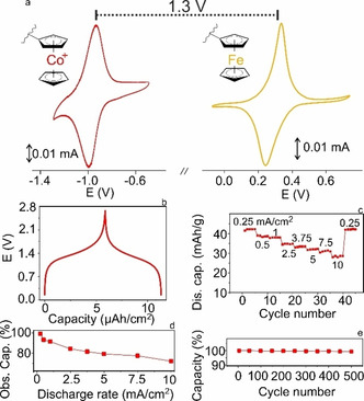
Battery performance of the PCo@rGO–PFc@rGO test cell. a) CVs of PCo@rGO (left, red) and PFc@rGO (right, orange) coated on GC substrates in 0.1 M LiClO4/aq. at v=10 mV s−1; polymer/rGO=9.5/1. b) galvanostatic charging‐discharging curves of the test‐cell at 1 mA cm−2 (corresponding to 20 A g−1); c) Cycling performance of test cell at different rates (0.25 mA cm−2–10 mA cm−2 (corresponding to 5, 10, 20, 50, 75, 100, 150 and 200 A g−1); d) Percentage of observed capacity (0.25 mA cm−2=100 %) vs. mA cm−2 rates; e) Discharge capacity of test cell over 500 galvanostatic charge‐discharge cycles at 0.5 mA cm−2.
Reversible electrochemical energy storage for mobile devices is dominated today by Li‐ion batteries. In these accumulators, Li+ intercalate reversibly into the surface‐confined lattice of inorganic, rigid and bridle, redox‐active cathodic materials, and graphitic carbon plays the role of the likewise rigid complementary anodic Li‐intercalation compound. A serious degradation phenomenon is the cracking of the rigid host due to repeated (de‐)intercalation of Li ions. ORBs are exciting alternatives due to their high‐power‐density, and flexibility, but these, generally non‐crystalline materials have been blamed for their change in volume upon (dis‐)charging, at least when considering the anode and the cathode materials separately. In the current work, we show that the cobaltocene ion breathing is reciprocal to the ferrocene height breathing. In a closed‐cell, (dis‐)charging of the battery is smooth and does principally not change the internal pressure. Furthermore, the inherent flexibility of organic non‐crystalline materials opens the possibility to fabricate thick flexible complete cells—never achievable with materials consisting of thick inorganic crystalline lattices.
A common objection is the low conductivity of ORBs. However, our metallocene battery shows excellent current densities attributed to the following reasons:
the use of two metallocenes known for their high electron transfer self‐exchange rates and the controlled architecture of charge storing material (the metallocene polymers) on the precursor conductive binder (GO) by molecular self‐assembly leading to GO wrapped by metallocenium in a stackable, porous 2D‐structure on the current collector;
the controlled in situ transformation of GO to rGO without loss of the supramolecular structure that is, its activation, resulting in charge storing films with excellent ion‐ and ‐electron‐percolation properties.
Overall, we believe that the combination of facile reciprocal height breathing in the soft structure of organic batteries with the inherent ultrafast ET self‐exchange rate of organic redox materials allows the preparation of durable high‐power‐density batteries. The choice of materials in the current study is optimized for fast kinetics and not for high energy density. However, the large thickness scalability can make up for the reduced energy density.
Conflict of interest
The authors declare no conflict of interest.
Supporting information
As a service to our authors and readers, this journal provides supporting information supplied by the authors. Such materials are peer reviewed and may be re‐organized for online delivery, but are not copy‐edited or typeset. Technical support issues arising from supporting information (other than missing files) should be addressed to the authors.
Supplementary
S. M. Beladi-Mousavi, S. Sadaf, A.-K. Hennecke, J. Klein, A. M. Mahmood, C. Rüttiger, M. Gallei, F. Fu, E. Fouquet, J. Ruiz, D. Astruc, L. Walder, Angew. Chem. Int. Ed. 2021, 60, 13554.
Contributor Information
Dr. Seyyed Mohsen Beladi‐Mousavi, Email: mohsen.bmousavi@gmail.com.
Prof. Dr. Lorenz Walder, Email: lowalder@uos.de.
References
- 1. Ding Y., Zhao Y., Li Y., Goodenough J. B., Yu G., Energy Environ. Sci. 2017, 10, 491–497. [Google Scholar]
- 2. Hultgren V. M., Mariotti A. W. A., Bond A. M., Wedd A. G., Anal. Chem. 2002, 74, 3151–3156. [DOI] [PubMed] [Google Scholar]
- 3. Frew J. E., Hill H. A. O., Eur. J. Biochem. 1988, 172, 261–269. [DOI] [PubMed] [Google Scholar]
- 4. Astruc D., Ornelas C., Ruiz J., Chem. Eur. J. 2009, 15, 8936–8944. [DOI] [PubMed] [Google Scholar]
- 5. Abraham K. M., Pasquariello D. M., Willstaedt E. B., J. Electrochem. Soc. 1990, 137, 1856–1857. [Google Scholar]
- 6. Astruc D., Eur. J. Inorg. Chem. 2017, 6–29. [Google Scholar]
- 7. Wei X., Pan W., Duan W., Hollas A., Yang Z., Li B., Nie Z., Liu J., Reed D., Wang W., Sprenkle V., ACS Energy Lett. 2017, 2, 2187–2204. [Google Scholar]
- 8.
- 8a. Beh E. S., De Porcellinis D., Gracia R. L., Xia K. T., Gordon R. G., Aziz M. J., ACS Energy Lett. 2017, 2, 639–644; [Google Scholar]
- 8b. Ding Y., Zhao Y., Yu G., Nano Lett. 2015, 15, 4108–4113; [DOI] [PubMed] [Google Scholar]
- 8c. Hwang B., Park M.-S., Kim K., ChemSusChem 2015, 8, 310–314; [DOI] [PubMed] [Google Scholar]
- 8d. Zhao Y., Ding Y., Song J., Li G., Dong G., Goodenough J. B., Yu G., Angew. Chem. Int. Ed. 2014, 53, 11036–11040; [DOI] [PubMed] [Google Scholar]; Angew. Chem. 2014, 126, 11216–11220. [Google Scholar]
- 9.
- 9a. Poizot P., Dolhem F., Energy Environ. Sci. 2011, 4, 2003–2019; [Google Scholar]
- 9b. Muench S., Wild A., Friebe C., Häupler B., Janoschka T., Schubert U. S., Chem. Rev. 2016, 116, 9438–9484. [DOI] [PubMed] [Google Scholar]
- 10.
- 10a. Park K. S., Schougaard S. B., Goodenough J. B., Adv. Mater. 2007, 19, 848–851; [Google Scholar]
- 10b. Su C., Ji L., Xu L., Zhu X., He H., Lv Y., Ouyang M., Zhang C., RSC Adv. 2015, 5, 14053–14060; [Google Scholar]
- 10c. Su C., Wang L., Xu L., Zhang C., Electrochim. Acta 2013, 104, 302–307; [Google Scholar]
- 10d. Su C., Ye Y., Xu L., Zhang C., J. Mater. Chem. 2012, 22, 22658–22662. [Google Scholar]
- 11.
- 11a. Zhong H., Wang G., Song Z., Li X., Tang H., Zhou Y., Zhan H., Chem. Commun. 2014, 50, 6768–6770; [DOI] [PubMed] [Google Scholar]
- 11b. Tamura K., Akutagawa N., Satoh M., Wada J., Masuda T., Macromol. Rapid Commun. 2008, 29, 1944–1949. [Google Scholar]
- 12. Tang C., Ren L., Google Patents, 2012.
- 13. Beladi-Mousavi S. M., Sadaf S., Walder L., Gallei M., Rüttiger C., Eigler S., Halbig C. E., Adv. Energy Mater. 2016, 6, 1600108. [Google Scholar]
- 14.
- 14a. Zhou Y.-N., Ma J., Hu E., Yu X., Gu L., Nam K.-W., Chen L., Wang Z., Yang X.-Q., Nat. Commun. 2014, 5, 5381; [DOI] [PubMed] [Google Scholar]
- 14b. Beladi-Mousavi S. M., Pumera M., Chem. Soc. Rev. 2018, 47, 6964–6989; [DOI] [PubMed] [Google Scholar]
- 14c. Beladi-Mousavi S. M., Pourrahimi A. M., Sofer Z., Pumera M., Adv. Funct. Mater. 2019, 29, 1807004; [Google Scholar]
- 14d. Sun J., Lee H.-W., Pasta M., Yuan H., Zheng G., Sun Y., Li Y., Cui Y., Nat. Nanotechnol. 2015, 10, 980. [DOI] [PubMed] [Google Scholar]
- 15. Kapustinskii A. F., Q. Rev. Chem. Soc. 1956, 10, 283–294. [Google Scholar]
- 16.
- 16a. Beladi-Mousavi S. M., Sadaf S., Mahmood A. M., Walder L., ACS Nano 2017, 11, 8730–8740; [DOI] [PubMed] [Google Scholar]
- 16b. Beladi-Mousavi S. M., Plutnar J., Pumera M., ACS Appl. Mater. Interfaces 2020, 12, 55936–55944. [DOI] [PubMed] [Google Scholar]
Associated Data
This section collects any data citations, data availability statements, or supplementary materials included in this article.
Supplementary Materials
As a service to our authors and readers, this journal provides supporting information supplied by the authors. Such materials are peer reviewed and may be re‐organized for online delivery, but are not copy‐edited or typeset. Technical support issues arising from supporting information (other than missing files) should be addressed to the authors.
Supplementary