



Abstract
Electrical microstimulation has enabled partial restoration of vision, hearing, movement, somatosensation, as well as improving organ functions by electrically modulating neural activities. However, chronic microstimulation is faced with numerous challenges. The implantation of an electrode array into the neural tissue triggers an inflammatory response, which can be exacerbated by the delivery of electrical currents. Meanwhile, prolonged stimulation may lead to electrode material degradation., which can be accelerated by the hostile inflammatory environment. Both material degradation and adverse tissue reactions can compromise stimulation performance over time. For stable chronic electrical stimulation, an ideal microelectrode must present (1) high charge injection limit, to efficiently deliver charge without exceeding safety limits for both tissue and electrodes, (2) small size, to gain high spatial selectivity, (3) excellent biocompatibility which ensure tissue health immediately next to the device, and (4) stable in vivo electrochemical properties over the application period. In this review we describe in detail the challenges in chronic microstimulation. To aid material scientists interested in neural stimulation research, we introduce the in vitro and in vivo testing methods for assessing stimulation functionality and longevity and provide a detailed overview of recent advances in electrode material research and device fabrication for improving chronic microstimulation performance.
Keywords: chronic neural stimulation, conducting polymers, metals, carbon materials
1. Introduction
Electrical microstimulation is a technique in which current is passed through a microelectrode for the excitation of neural tissue. It is an invaluable tool in neuroscience research to dissect neural circuits, relate brain areas, and identify relationships between brain structure and behavior.[1–3] Therapeutically, electrical microstimulation has enabled partial restoration of vision,[4] hearing,[5] movement,[6] somatosensation,[7] and autonomic functions,[8] and has improved organ functions by electrically modulating neural activities.[9] The growing field of neuromodulation is valued approximately at $8.1 billion in 2019 and is expected to grow more than 13.1% by 2027.[10] Of these, cochlear implants are the most successful and widely deployed, which restore hearing to profoundly deaf patients. As of December 2012, there are 324200 registered devices implanted worldwide.[11]
Microelectrodes are electrodes with geometric surface areas on the order of 2000-10000 μm2,[12] which are dramatically smaller than macroelectrodes used for traditional deep brain stimulation.[13] The smaller electrode size offers increased spatial selectivity but poses unique challenges in terms of electrode material requirements. The reduction in the electrode area reduces the surface area for electrochemical reactions, which increases impedance and decreases charge injection. To achieve effective activation of neural tissue safely, sufficient charge is required without exceeding potentials for irreversible electrochemical reactions.[12] Platinum (Pt) is widely used for current auditory and visual prosthesis.[14] While smooth Pt has charge injection limit (CIL) below the threshold for activation for these applications, there is a need for increased CIL for higher resolution next generation devices. Recently, novel materials have been introduced to reduce impedance and improve CIL and new fabrication techniques of traditional metals have emerged. Examples of such materials are iridium oxide (IrOx),[15, 16] titanium nitrite (TiN),[17] glassy carbon (GC),[18] nanostructured Pt,[19] and conducting polymer poly (3, 4-ethylenedioxythiophene) (PEDOT) doped with different counter ions.[20–22] These materials have shown dramatic improvement in CIL, on the order of mC/cm2, higher than smooth Pt (0.035-0.1 mC cm−2) in vitro, thanks to the high effective surface area and/or inherently reversible faradaic reactions. However, the CIL of porous Pt and IrOx substantially decreases in vivo, and PEDOT, the most stable of the conductive polymers, has shown degradation in chronic practical application.[12, 23] While much progress has been made in understanding and improving the chronic stability of PEDOT based materials [23, 24] other high CIL and stable electrode materials have emerged, including various high surface area carbons and electrodeposited Pt/Ir alloys.[25–29]
Additionally, the implantation of an electrode array into the neural tissue triggers foreign body responses such as inflammation and neuronal loss (reported in detail in [30–32]). Numerous investigations have shed light on the vascular and cellular pathways and time-course of the foreign body response to neural recording devices. [32–34] However, the electrode tissue interface becomes more complex for implants that also deliver electrical stimulation. Not only does the implant itself initiate foreign body response, but the electrical stimulation also has the potential to cause additional damage to both the electrodes and the tissue, which ultimately will lead to decreased stimulation efficacy.[12, 35]
Thus, to achieve stable chronic stimulation, an ideal microelectrode must present (1) low impedance to be able to efficiently deliver charge without exceeding safety limits for both tissue and electrodes, i.e., high charge injection limit (CIL), (2) small size, to gain high spatial selectivity, (3) biocompatible, and (4) stable in vivo electrochemical properties for safe and efficacious electrical stimulation.
To meet these requirements, we need to dissect the electrode tissue interface during repetitive electrical stimulation. From a materials perspective, we need to understand the mechanism of material failure, and from a biological perspective, the cellular and molecular mechanisms in implantation and stimulation induced tissue responses. In this review we provide details about the challenges in chronic microstimulation. To aid material scientists interested in neural stimulation research, we introduce the in vitro and in vivo testing methods for assessing stimulation performance and provide a detailed overview of the recent research and development in electrode materials for improving performance in electrical stimulation including new fabrication methods.
2. Mechanism of Electrical Stimulation
2.1. Activation of neural tissue
The neuronal membrane at its resting level is more permeable to potassium ions (K+) than sodium ions (Na+). Na+-K+ pumps on the membrane actively pump 2 K+ in and 3 Na+ out of the cell for every adenosine triphosphate (ATP) consumed to maintaining a steady K+ and Na+ gradient across the neuronal membrane, resulting in a negative resting membrane potential of ~−70 mV (Figure 1a).[36] When an external anodic electrical stimulation is applied via an extracellular electrode, the membrane voltage becomes less negative, and when this voltage exceeds the threshold (~55 mV), voltage-gated Na+ channels opens and the rapid influx of Na+ ions initiates an action potential, also called a neuronal spike or firing.[37] Modulating the neuronal spiking or action potentials of neuronal populations for a specific brain region can help augment or restore neurological functions. The extracellular voltage (Ve) is directly related to the amplitude of the injected current Iin (A), the distance between the cell and the source of the current r (m), and the conductivity of stimulated environment, σ (S m−1) (eq 1).[38, 39]
| (eq1) |
Figure 1.

a) Schematic showing electrodes stimulate excitable tissues via applying a voltage, the cellular membrane of the targeted neurons was depolarized, which results in firing of action potentials. Adapted from [38] with permission. b) Faradaic charge transfer occurs via irreversible and reversible faradaic reactions. c) Capacitive transfer is achieved via charging and discharging of the electric double layer (EDL) formed by accumulation of ions on the oppositely charged electrode surface.
2.2. Faradaic vs non faradaic charge transfer
During electrical stimulation, electronic currents that are passed from instrumentation to the electrodes are converted to ionic currents at the electrode/tissue interface. The charge transfer mechanisms at the interface can be either faradaic or capacitive. The faradaic process is a reaction in which surface confined species are oxidized or reduced. These reactions may be irreversible or reversible when an opposite stimulation pulse is applied. For example, the oxidation of the electrode metal into metal ions may be irreversible if the metal ion diffuses away before the reversing pulse is applied (Figure 1b, top panel). On the other hand, IrOx may undergo oxidation and reduction between the different iridium states (Ir2+, Ir3+,Ir4+, Ir5+), and these reactions are reversible (Figure 1b, lower panel).[16] Depending on the materials and stimulation parameter design, reversible faradaic processes can provide high charge injection capability, while irreversible processes can lead to electrode corrosion and release of toxic products and must be avoided.
On the other hand, capacitive charge transfers involve the charging and discharging of an electric double layer, or charge stored across a thin, high-dielectric-constant oxide at the electrode-electrolyte interface, Figure 1c.[38] Usually, a capacitive process is a safer charge injection mechanism due to the absence of addition or removal of a chemical species or a morphological change during a stimulation pulse, reducing the likelihood of damage to the electrode or the surrounding tissue.
3. Challenges in chronic microstimulation
Numerous challenges in chronic electrical stimulation have been reviewed extensively by Merrill et al, Cogan et al, Boehler et al, and Shiavone et al. [35] [12, 40, 41]. These challenges can be categorized into (1) charge injection limit, (2) tissue health and function, and (3) material stability.
3.1. Charge injection limit
One of the defining metrics for safe electrical stimulation is the charge injection limit (CIL), which characterizes the performance of the electrode in relation to the electrochemical redox window of water. charge injection limit is the maximum charge density (mC cm−2) that an electrode can inject before reaching the water electrolysis potential. Exceeding the CIL could lead to electrode deterioration and tissue damage. [42] As an estimate for metals like platinum, CIL is the charge density at which −0.6V or +0.8 V are reached at the electrode.[43] To effectively stimulate a functional output, the delivered charge needs to be above the threshold charge density. In human neural prostheses applications, the threshold charge density ranges between 0.005-0.306 mC cm−2 (1000-2000 μs pulse width) for epi-retinal stimulation.[44, 45] and 0.19-2.3 mC cm−2 (200 μs pulse width) for intracortical visual stimulation.[46] Traditional stimulating electrode materials like platinum with a CIL of 0.05-0.15 mC cm−2 [43] cannot meet the full range of charge injection requirements for these applications, which drives the need for the development of high charge injection electrode materials.
4. Stimulation related in vivo challenges
4.1. Definition of relevant terminology
In the field of neuromodulation, various terminologies are assigned to features of electrical stimulation paradigm. Since there is variability to how these features are reported, herein we provide definitions to commonly used terminologies in describing stimulation paradigms.
Charge (C): basic property of matter, which causes it to experience a force when placed in an electromagnetic field. An electric charge can be positive or negative, and represented with the unit coulomb. Charge is equivalent to current multiplied by the duration (time) of the current.
Charge per phase (C/ph): the integral of the stimulus current over one phase of a stimulation pulse. For example, the charge per phase of a 200 μs cathodic-leading pulse at 20 μA is 4nC per phase.
Charge density (mC cm−2): electric charge per unit area of a surface.
Power density (W cm−2): energy delivered from the electrode to the site of stimulation. W (joules per second) = V (joules per coulomb) x A (coulombs per second).
Stimulation frequency: the rate at which an electrical stimulation is applied over time. E.g., in a 50 Hz stimulation pulse train, there are 50 electrical pulses applied per second.
Pulse width (PW): the elapsed time between the rising and falling edges of a pulse.
Interphase delay: the interphase delay is the time between the cathodic and anodic phases of a stimulation pulse with no applied current or voltage. It has been found to (1) lower stimulation threshold see review [47] and (2) when limited within 100 μs, the interphase delay can prevent the corrosion of electrodes. [35]
Duty cycle: in engineering, duty cycle is defined over a single pulse duration. For instance, a pulse with 50% duty cycle could imply that a pulse with a period of 400 μs that is active or non-zero for 200 μs. However, in many stimulation studies, the “duty cycle” has been used to describe the percentage of time when the stimulation is ON. For instance, a 25% duty cycle stimulation of a 400 μs biphasic pulse applied at 50 Hz can be interpreted as that this stimulation is on 25% of the time, also known as the percentage of effective stimulation time. [48–51]
Train duration: the length of time in which stimulation is ON.
4.2. Biological tissue damage from electrical stimulation
Efficacy and safety are important factors for chronic electrical stimulation. The existing inflammation due to electrode insertion can be exacerbated by electrical stimulation. There have been reports of electrical stimulation induced vasoconstriction, thrombosis in venules and arterioles and blood brain barrier breakdown within 30 s of stimulation at a charge density threshold necessary for a sensorimotor response or for monophasic pulses at power densities greater than 0.5 mW cm−2.[52–54] Moreover, electrochemical products because of irreversible faradaic charge injection have been reported to increase the presence of reactive oxygen species, which severely damages myelin.[55–60] McCreery et al stimulated the cortex with iridium microwires with IrOx contacts at 4 nC ph−1 pulsed continuously for 8 h per day for 30 days and observed neuronal cell loss within ~60μm – 150 μm of a microelectrode. However, when stimulating at 2 nC ph−1, no apparent loss in neuronal cells were observed (AIROF, GSA: ~2000 μm2, 50 Hz, 50% duty cycle).[61] Conversely, other studies have reported no significant additional damages to the brain region stimulated via sputtered IrOx on silicon arrays compared to unstimulated arrays, even with up to 20 nC ph−1 stimulation for 4 hours per day for 6 months (SIROF, GSA: ~2000 μm2, 300 Hz, 25-50% duty cycle, train durations of 1 s or 5 s). [62, 63]While the authors concluded that the ability to stimulate the cortex was maintained over long periods, a small fraction of stimulated region showed decreased sensitivity to electrical stimulation, likely due to the chronic tissue damage induced by the presence of the implant.[63] It is important to note that while the studies conducted by McCreery and the Otto group used similar electrode arrays with the same tip material and geometric surface areas, an “apples-to-apples” comparison may not be drawn between the studies. First, the frequency of stimulation is different between the two studies, and literature has suggested the potential neuroprotective role of various stimulation frequencies, leading to potentially different observations of neuronal loss nearby the implant [64–66]. Second, while both studies used IrOx as stimulating site material, the activated IrOx used by McCreery has been demonstrated to have a lower threshold of electrode material degradation compared to the sputtered IrOx used by the Otto group. [67]
4.3. Detection threshold variability from electrical stimulation
Depending on the desired functional outcome, different metrics are used to evaluate the functional efficacy.[2, 7, 68–70] For the detection of a sensory stimulus in animals, lever press is used to translate an animal’s detected electrically evoked sensation.[71] In humans, the detection threshold may be a vocalization of detected sensation to a given stimulus. Depending on the stimulation pulse design, frequency, duty cycle, and duration, varying stability in detection thresholds have been documented. Bartlett et al. reported that with electrodes implanted in the striate cortex in the macaques, when stimulation was applied continuously for 1-8 hours, a temporary or permanent elevation in detection threshold was observed. The main contributor to this phenomenon was hypothesized to be hydrolysis, the evolution of gas from the electrode surface created an additional resistive pathway, requiring an increase in currents. However, even by limiting the voltage level of stimulation to be within the range of hydrolysis while also using tantalum pentoxide electrodes which inject charge via predominantly capacitive stimulation (reducing the risk of irreversible faradaic charge injection), there was still a rise of detection threshold.[72] On the contrary, there have been reports of improved threshold detection over thousands of stimulated trials.[69] In this experiment, electrodes were acutely inserted into the brain and advanced regularly between threshold measurements. This method ensured that each brain region was not subjected to prolonged electrical stimulation. The cause of improved detection threshold over thousands of trials was posited to be due to changes in functional connectivity within the stimulated cortex.[73, 74] Regarding elevated detection threshold, it was hypothesized that the stimulating charge density contributed to potential damages to neuronal tissue. The loss of behavioral sensitivity to applied stimulation may also be due to potentially harmful by-products of irreversible redox reactions at the electrode surface which could increase oxidative stress, induce pH change, or be toxic. For example, the aforementioned McCreery study reported corrosion of the iridium electrode tip and deposition of elemental iridium in the nearby tissue. While these metal deposits can be speculated to be adverse for neuronal health, the corrosion of the electrode is bound to affect stimulation efficiency. Furthermore, depending on the stimulation frequency, there may be persistent depression of neuronal excitability following stimulation of the cortex that last for several days following the cessation of the stimulation.[50]
4.4. Material stability
The integrity of the implanted electrode faces unique challenges in vivo that often lead to material degradation. Comprehensive analysis of failure modes for various styles of electrode arrays have been extensively studied and reviewed.[30, 75–77] Aside from the most frequently occurring mechanical failure of the I/O connector, other failure mechanisms include mechanical defects from fabrication, chemical, physicochemical and electrochemical reactions, and the interaction of mechanical and chemical stresses.[78] All of these failures can be characterized by varying amounts of fracture, dissolution and delamination of the electrode sites and/or insulation over the implantation duration. For multi-electrode arrays, insulation corrosion and delamination cause additional interstitial fluid to intrude under existing insulations, resulting in shortages between channels and drastically decreasing electrical impedance.[79–81] For stimulation applications, the excessive fluid under insulation can shunt the stimulating current, requiring an increase in stimulation amplitude to activate the tissue, resulting in poor stimulation efficacy. Additionally, electrical stimulation can also accelerate the rate of corrosion for traditionally used stimulating materials such as tungsten and stainless steel.[82] Even though inert metal such as platinum is considered resistant to corrosion, and IrOx has demonstrated much higher charge injection limit,[83, 84] they can degrade or detach from the substrate upon high charge injection or prolonged stimulation load.[22, 77]
5. Testing of Stimulating Electrodes
Electrode materials are to be tested for their electrochemical features, electrochemical stability under stimulated in vivo conditions, and changes to electrode surface compositions after persistent use. While there is some consensus in testing methods for electrode materials, the field of neural electrode technologies lack a unified and consistent testing method. Boehler et al. recently reviewed traditionally used methods for electrode and proposed standardized methods for systematic testing of electrode materials for benchmarking across research and industry laboratories. [41] With the emergence of soft electronics for neural interfacing, care must be taken in testing and interpreting results for stretchable electronics using conventional methods. This is because when soft and flexible electrodes are deformed, their dimensions may change, which results in a change in electrochemical properties. Shiavone et al provided a detailed review and guidelines for these considerations in testing soft electrode materials. [85]
5.1. Electrochemical Methods
Electrochemical measurements such as cyclic voltammetry (CV), electrochemical impedance spectroscopy (EIS) and voltage transient measurement are essential methods for the characterization of electrode materials. CV measures the current response to a cyclic potential sweep and is a powerful tool with which we can investigate the reduction and oxidation processes of molecular species at the surface and estimate the charge storage capacity of an electrode. EIS measures the impedance of a system at a spectrum of input frequencies. EIS can be measured by applying a small sinusoidal AC potential with varying frequency (eg. 10-50 mV, 0.1-105 Hz) to a two or three-electrode system and measuring the resulting phase-shifted current. Magnitude of the impedance at the relevant recording and stimulation frequencies are often used to indicate or compare the ease of electrode in detecting neural signal or injecting stimulation current. Furthermore, using the real and the imaginary impedances from the EIS, equivalent circuit models can be established which provides a quantitative understanding of contributing factors that influence charge transfer. For example, we can be informed about capacitive and faradaic charge transfer, electrode surface heterogeneity, and potential shunting of electrical currents. In addition, tissue encapsulation of the electrode will be reflected from modelled circuit components. While both CV and EIS are commonly used to characterize both recording and stimulation electrodes, voltage transient measurement is specifically relevant to stimulation applications. Voltage transient measured by recording the voltage response to a specific stimulation current pulse and is used to determine the charge injection limit (CIL) of a stimulation electrode. Additional details regarding all three electrochemical methods can be found in an excellent review by Boehler et al.[86]
CIL is conventionally defined as the maximum charge that can be safely injected to electrodes without reaching the water window[87]. While it is true that exceeding the CIL may cause water hydrolysis and impart damages to both the electrode and the tissue, one may not assume absolute safety when stimulating within the water window. First, in the case of conducting polymers, the oxidation and reduction occurring within the water window may cause the conducting polymer network to swell and contract which can threaten its mechanical integrity. Second, as excellently pointed out in the recent review by Boehler et al. that oxygen reduction can occur at voltages less than the water window, generating reactive oxygen species at the interface, which is harmful to both the electrode and the tissue. [41, 88]. It is worth noting that CIL is dependent on the measurement conditions such as stimulation pulse width and the electrode size. For example, it was shown that under shorter pulses, the central part of a circular electrode is underutilized due to the non-uniform current distribution (higher at the boundaries), and therefore the resulting CIL is smaller.[89] With longer pulses, the reactions can to spread all over the whole surfaces and higher CIL are expected.[90] [91]Similarly, the electrode size also plays a role in determining CIL, where smaller electrodes have significantly higher CIL because of charge transfer is less transport limited.[12] Therefore CILs should be measured under the same conditions when comparing between electrode materials.
5.2. Testing of chemical and mechanical integrity
Chemical analyses such as Raman spectroscopy, x-ray photoelectron spectroscopy, SEM-EDAX and inductively coupled plasma mass spectrometry (ICP-MS) are also used to study potential changes to the chemical compositions of material surfaces before and after aging or stimulation, as performed by Negi et al in evaluating the degradation of iridium oxide from continuous electrical stimulation. Using ICP-MS, they quantified the iridium concentration in the solution from stimulating the electrodes at different charge densities and concluded that sputter coated iridium oxide electrodes have higher damaging threshold for the material characterized by EIS, CV, ICP-MS, and SEM (60 —80 nC charge per phase at 1—1.9 mC cm−2 charge density), compared to activated iridium oxide electrodes (40—50 nC charge per phase at 0.5—0.9 mC cm−2 charge density).[67, 92, 93] Furthermore, to characterize the integrity of the electrode coating beyond the surface, focused ion beam (FIB) in combination with SEM can be used. In a recent study by Caldwell et al. FIB was employed to probe the cross section of component materials of the electrodes, which enabled discovery of film thinning of parylene-C from in vivo aging as well as signs of silicon erosion in vivo underlying the IrOx tip metallization of Utah arrays. [77]
To evaluate the adhesion of a coating to a certain substrate and any possible delamination due to mechanical stress, the Scotch tape test can be performed on coatings deposited on relatively large substrates. As documented in American Society for Testing and Materials (ASTM) standards, cuts are made to the coating before the application of the tape.[94] The tape is then applied and removed, and the integrity of the coating is examined using imaging techniques.[95–97] Indeed, it would be difficult to perform the Scotch tape test on microelectrodes, however the information obtained using a macroelectrodes may still apply to microelectrodes especially in the case of conducting polymers with the same substrate material. Furthermore, sonication can be used to test coating integrity. For instance, to evaluate the stability of the PEDOT with NH2 functional groups in the repeat units, the Martin group ultrasonicated the coating for 1 hour and observed no signs of delamination or cracking whereas typical PEDOT coatings degrade after only seconds of sonication. The stability of PEDOT-NH2 was attributed to the amine’s strong covalent bonding to the metal substrate.[17] Since flexible devices are often subjected to bending forces during handling and in vivo use, adhesion needs to be accessed upon bending. Castagnola et al tested flexible ECoG devices coated with PEDOT/CNT. The flexible devices were rolled around a wire with radii of 1.5 and 0.5 mm and electrochemical measurements were used to evaluate the stability of the coating after different degrees of bending.[98]
5.3. Thermal accelerated aging test
The vast parameter space in designing an electrode requires rapid understanding of its long-term performance, making it difficult to test each electrode design in vivo. To gain understanding of the stability of an electrode material, electrode aging tests have been developed to mimic the in vivo environment. ASTM states that accelerated aging techniques should be based on the assumption that the chemical reactions that occur in the degradation of materials follow the Arrhenius reaction function, which describes that the chemical reaction rate depends on the temperature.
Where k is the chemical reaction rate, A is a constant, Ea is the activation energy, R is the gas constant, and T is temperature in Kelvin. The aging multiplier, or the accelerating factor, K, at testing temperature T1, over body temperature (37 °C), is described as the following:
The equation makes use of the 10-degree (Q10 = 2) rule which states that the rate of chemical reaction doubles for every 10-degrees increased.[99, 100] An upper limit of 60 °C is imposed to exclude possible chemical reactions or physical changes to materials not occurring at body temperature.[101] For mimicking the biological environment in the presence of a foreign body, more aggressive chemical environments may be required. The injury of the neural tissue upon implantation of an electrode triggers a host of immune response, activating microglia and macrophages that secrete pro-inflammatory cytokines and produce various cytotoxic factors such as excitatory amino acids and reactive oxygen species(ROS).[32] Some of these factors such as ROS not only causes tissue damage, they can also be detrimental to the electrode materials. Takmakov et al designed a rapid accelerated aging (RAA) protocol which includes ROS generated from 10-20 mM hydrogen peroxide with the testing environment maintained at 87 °C.[102] Using this system, they tested commercially available microelectrode arrays with periodic collection of electrochemical impedance spectroscopy data, as well as performing ICP-MS of the soaking solution after RAA to assess elements that may be detached from the electrode surface. Impedances at frequencies 1-10 Hz had the greatest change after the aging process, however there was not a one-to-one correlation with changes in impedances and damages to the electrode surface observed by scanning electron microscopy. These results indicate that impedance may not be the best metric to pinpoint material related damages. A potential explanation is that the impedance frequency spectra are influenced by factors not limited to material related damage. In the frequency range where neural electrodes are typically studied, the lower frequency region (1-10 Hz) is primarily influenced by the electrode double layer capacitance, electrode material surface morphology and topology. The intermediate frequency range (0.1-10 kHz) has a mixed influence from electrode coatings, the implant position and tissue responses. The high frequency range (10 k-10 MHz) reflects electrolyte characteristics and resistance of the conducting materials. The boundaries of these frequency regions are not fixed, and as the electrodes become smaller, the boundary moves towards higher frequencies.[103] Equivalent circuit modeling may be a more comprehensive evaluation of changes to the electrode properties and electrode-tissue interface in vivo.[104–106] While the changes in RAA system simulated impedance changes observed after 6 months of in vivo implantation, one major limitation lies in the elevated testing temperature (87 °C). While most electrode materials have a high tolerance to heat, other materials such as PEDOT/PSS undergo micro-structural changes as temperatures approach 100 °C and will not operate in the same condition as it does in the body temperature.[107] Therefore, the RAA system is limited in its use for testing a wide array of electrode materials.
5.4. In vitro electrical stimulation test
For stimulation applications, electrode materials may be stimulated at physiologically relevant temperature ranges for prolonged periods. For evaluating stimulation damaging stimulation thresholds of sputtered IrOx (SIROF) and AIROF electrodes on Utah arrays, Negi et al subjected these materials to biphasic stimulations for 7 hours (> 1 million pulses, 50 Hz). In conjunction with electrochemical methods, the authors also performed ICP-MS to examine iridium concentrations in the stimulated solution and concluded that SIROF is better suited for chronic stimulation as it has a higher damage threshold compared to AIROF (damage threshold for SIROF: 60 nC, 1.9 mC cm−2; AIROF: 40 nC, 0.5 mC cm−2, geometric surface area(GSA): 3100 μm2).[67]. Similar methods were employed by Green et al. in investigating the performance of PEDOT/pTs coated electrodes for electrical stimulation. Biphasic pulses with charge densities of 88 μC cm−2 and with frequencies at 2 kHz were applied to electrodes in 15% serum supplemented cell culture medium for 16 days, totaling 2.8 billion stimulation cycles. Media was refreshed every 48 hours to ensure the presence of active proteins. CSC and SEM evaluations of stimulated PEDOT/p-toluenesulfonate (pTS) showed no significant differences to PEDOT/pTs electrodes without stimulation. Stimulation parameters from other electrical accelerated aging are summarized in Tables 2–4.
Table 2.
Summary of metal, metal oxide and ceramic materials.
| Electrode material | GSA (μm2) | Duration of testing | stimulation paradigm | CIL(mC cm−2) | CSC(mC cm−2) | Imp @1kHz(Ω) | ECM | In vivo | Ref |
|---|---|---|---|---|---|---|---|---|---|
| SIROF | 200 | 21 days | Amp:20 μA, PW:0.2 ms, IPD: 0.1 ms | - | 59±38 | 166.1 ± 103.1 k | - | - | [151] |
| SIROF | 2000 | 90 days | - | 2 | 34.3±21.7 | 6.7 ± 0.2 k | Rs(Rct||CPE) | - | [137] |
| SIROF | 20 | - | - | 3.33 ± 0.5 | 109 ± 2 | 241 ± 11 k | - | - | [139] |
| SIROF | 1960 | - | - | 1.4 ± 0.2 | 49 | 12 ± 1.4 k | - | - | [139] |
| SIROF | 2000 | 9 weeks (1B stim) | Amp:20 uA, PW:0.2 ms | 3.57 | ~ 30 | ~2 k | - | - | [152] |
| SIROF | 150 | - | 0.2 ms pulse width, 50 Hz | 15.3 | 35±2.2 | 90.2 ± 26.1 k | - | Rat motor cortex, basal ganglia of Zebra Finch | [153] |
| AIROF | 877 | - | - | 3.9 | 23 | - | - | - | [142] |
| AIROF | 1130 | - | - | 4.9 | 12 to 55 | - | - | - | [16] |
| AIROF | 2024 | - | - | 3.3 | 29 | - | - | - | [16] |
| AIROF | 2015 | - | - | 9.6 | 25.1 | - | - | - | [16] |
| AIROF | 7850 | 12 hr | CV [−0.6, 0.8] 50Hz | 4.1 | - | 2.54 k | Rs(Rct||CPE) | - | [146] |
| AIROF | 2000 | 7 hrs | 2 mC/cm2 1.3 million or 3 mC/cm2 100s |
- | 22 | - | - | Cat, sensorimotor cortex | [154] |
| AIROF | 4000 | - | PW:0.2 ms | 5.75 | 11 | ~ 38 k | - | - | [17] |
| TIROF (thermal) | 5400 | - | - | - | - | - | - | - | [26] |
| RuOx | 200 | 21 days | Amp:20 μA, PW:0.2 ms, IPD:0.1 ms | - | 49±20 | 73.83 ± 59.91 k | - | Rat, motor cortex | [151] |
| Pt (nano) | 962 | time for 1.5B stim | PW: 0.2ms, 1.5 mC/cm2 | 3.0 ±0.1 | 5.333±0.0208 | ~ 15 k | - | Mice, medial septum, hippocampus | [19] |
| Pt | 2000 | EIS 90 days | - | 0.3 | 4.4±3.1 | 125±0.25 k | Rs(Rct||CPE) | - | [137] |
| Pt | 100 | - | - | - | 10±1.7 | 481.3 ± 67.9 k | - | - | [153] |
| PtIr(20%) | 14000 | - | Amp:100 μA, PW:0.1 ms, IPD:0.01 ms | 0.018-0.023 | - | - | - | Rat motor cortex | [138] |
| PtIr(20%) | 1105 | - | - | 0.3 | 5.6 | - | - | - | [142] |
| Ir | 1250 | - | - | - | 0.1 ±0.5 | 468.8 ± 13.3 k | - | - | [155] |
| Ir | 300 | 169 hrs (2.2B stim) |
Amp:6 μA, PW:0.1 ms | - | 10 | ~ 200 k | - | - | [144] |
| Au | 100 | Acute use | - | - | 2±0.3 | 2860 ± 300 k | - | - | [153] |
| Au | 800 | - | - | - | - | 850 k | - | - | [156] |
| Au (nano) | 800 | - | - | - | - | 30 k | - | - | [156] |
| ITO | 200 | 21 days | Amp:20 μA, PW:0.2 ms, IPD:0.1 ms | - | 1±2 | 1200 ± 500 k | - | - | [151] |
| ITO | 2500 | 2 months | - | - | - | 270 kΩ | - | - | [157] |
| TiN | 150 | - | PW:0.2 ms | 6.3 | 12±2.8 | 31.1 ± 7.3 k | - | - | [153] |
| TiN | 16000 | - | Amp:100 μA, PW:0.1 ms, IPD:0.01 ms | 0.072-0.194 | - | - | - | Rat motor cortex | [138] |
| TiN | 4000 μm2 | - | PW:0.5 ms | 0.9 | 2.47 | ~ 40 k | - | - | [17] |
Rs: solution resistance; Rct: charge transfer resistance; CPE: constant phase element.
Table 4.
Summary of studies using carbon-based materials
| Electrode Material | Substrate | Deposition Method | GSA [μm2] | Stim Duration | Stim Paradigm | CIL [mC cm−2] | CSC [mC cm−2] | Impedance @ 1kHz [Ω] | ECM | In vivo | Ref |
|---|---|---|---|---|---|---|---|---|---|---|---|
| GC | GC | pyrolysis | 70650 (300 μm dia.) | 3.5 billion cycles (1000 hours) | 0.25 mC cm−2, Ampl. :450 μA Pw: 400 μsec |
3 | 61.4 ± 6.9 | 5.8 ± 1.2 k | Rs (CPE|| (Rct)(W)) | - | [18] |
| porous graphene | - | direct laser pyrolysis | 62500 | 1 million cycles. | Amp: 0.75 mA Pw: 400 μs | 3.1 | 50 | 2 to 8 k | - | pial surface of the motor cortex | [28] |
| CNT fibers | - | high-throughput wet spinning of bulk grown CNTs | 1450 | 97M cycles (9 days) | Pw: 60 μs Freq:130 Hz. | 6.52 | 372 ± 56 | 11.2 ± 7.6 k | - | ipsilateral entopenducular nucleus | [189] |
| Graphene fibers | - | one-step dimensionally confined hydrothermal process using suspensions of graphene oxide | 1406.2 (75μm dia.) | 19 days | Pw: 60 μs Freq:130 [Hz]. | 10.1 ± 2.25 | 889.8 ± 158.0 (cathodic) | 15.1 ± 3.7 k | - | Yes subthalamic nucleus (STN) in Parkinsonian rats | [29] |
| Hybrid diamond/carbon fiber | - | 3200 | - | - | 25.08 ± 12.37 | - | - | Rs(Cc||Rp (Ccor||Rc)) | retinal cell cultures | [210] | |
| Reduced Graphene Oxide | - | wet-spun from liquid crystalline (LC) dispersions of GO and Laser treatment | 1923 (50 μm dia. Before laser treatment) | - | Amp: 103 ± 87 μA Pw: 500 μs | 14 ± 0.9 to 46 ± 2.9 | - | 4 k | Rs||CPE | Retinal ganglion | [187] |
| CNT | Pt | CVD | 923 ± 70 μm2 | 1 million pulses | 1.6 mC cm−2 Amp.: Pw:100 and 500 μs. | 4 | 58.5±10.6 | 59.6±11.2 k | - | - | [27] |
| MWCNT pillars | polysilicon | CVD | 5700 μm2 | - | Amp. 80 μA Pw: 1 ms | 1–1.6 | - | - | Rs (Zf||CPE) | primary neurons cultures | [188] |
Rs: solution resistance; Rct: charge transfer resistance; CPE: constant phase element; W: Warburg element; Zf: spreading resistance
5.5. Biological testing
5.5.1. In vitro
The evaluation of the biological effects of electrical stimulation requires methods that provide read-outs about the health status of the stimulated tissue. From a time and cost-efficient perspective, in vitro methods offer tremendous information for the prediction of the cytotoxicity of the stimulating material and the stimulation products in vivo. Stimulation material can be immersed in cell culture media to allow leachable toxic compounds to elute out. Stimulation may be applied to collect the stimulation byproduct in the media. The elution can then be added to cultured cells at different doses to access toxicity using quantitative viability assay such as the MTT assay or live/dead staining.[108, 109] The use of cell cultures also allows for efficient exploration within a large parameter space when microelectrodes are placed in direct contact with the cultured cells.[110, 111]
To be compliant with long term application and clinical use, stimulation devices are required to withstand the sterilization process with the most common being ethylene oxide (ETO) and steam. ETO is often used to sterilize medical devices with components that are sensitive to heat or moisture. When a new electrode material is developed, studies need to be performed to ensure the safety of the material after ETO or steam sterilization. For instance, Green et al sterilized their electrodes using ETO and found that while there were no significant changes to charge storage capacity and electrode potential compared to pre-sterilization condition, the drying conditions in the ETO sterilization process resulted in fine cracks on the PEDOT/pTs coatings.[112] For steam sterilization, Castagnola et al tested stability of PEDOT/CNT coated surfaces at 122 °C and 2 atmospheric pressure for 20 minutes and observed no significant change in the full spectrum electrical impedance.[113] A cell viability assay can be performed using the new material as the cell culture substrate before and after sterilization to confirm that there is no toxic ETO residue or degradation product.[23] If an electrode material passes the toxicity test, in vivo testing will be the next step.
5.5.2. Histology
Histological methods such as hematoxylin and eosin as well as immunohistochemistry (IHC) have been used for understanding tissue pathology. Traditional and modern reports of stimulation safety and the in vivo biocompatibility of implantable neural devices have utilized various forms of end point histology. Slices of tissue samples containing the electrode location can be stained with desired anti-bodies to observe cellular changes to the electrode tissue interface. IHC has a wide variety of markers that are used to indicate tissue health. NeuN and NF-200 are often used to evaluate quantifiable changes in neuronal cell body and axons near the implant respectively. Meanwhile, IBA-1 and GFAP are used to assess the presence of macrophages and astrocytes near the implant, respectively. The integrity of the blood brain barrier can be interrogated using IgG staining.[24, 114–118] These markers are typically evaluated as either cell count or intensity as a function of distance away from the implant.[33] While histological methods provide pathological information at the sub-cellular level, they do not provide real-time read out of the tissue response to electrical stimulation, potentially missing crucial transient information.
5.5.3. Electrophysiology
Electrophysiology can gauge network response to electrical stimulation and may also be used to probe the health of the neurons near the electrodes.[119–121] Unlike in vitro and histological methods, electrophysiology does not provide visual observation of the biological tissue near the electrode. Additionally, electrical artifacts evoked by stimulation prevent the detection of spiking activity adjacent to the electrode, obscuring the interpretation of experimental results. However, artifact removal is a possibility using computational methods.[122] Behavior analysis is a powerful tool for evaluation of functional electrical stimulation as it provides a one-to-one functional response to stimulation.[7, 123] However, it may not directly offer information on inflammatory tissue response or neuronal health.
5.5.4. Live imaging
Imaging has become an increasingly popular method for evaluating electrical stimulation for it allows the direct visualization of events occurring at the electrode-tissue interface in real time. Drawing from an arsenal of voltage- or calcium- sensitive dyes and transgenic tools that label the cells of interest, researchers can gain tremendous information about the transient responses to electrical stimulation. For instance, electrical stimulation induced cell permeability change was studied using brightfield and fluorescence imaging. A change was observed in the porosity of the cellular layer surrounding the electrode which resulted in a change in electrical impedance in vivo.[124] The Weiland group assessed stimulation safety pulse paradigm design for safe and selective retinal stimulation using optical coherence tomography and two-photon imaging.[125, 126] Using in vivo two-photon calcium imaging in mice, rats, and cat models, Histed et al revealed a sparse, distributed population of cortical neurons by electrical microstimulation via glass pipettes containing tungsten and platinum-iridium microwire electrodes.[127] The Kozai group investigated the calcium responses to prolonged electrical stimulation in Thy1-GCaMP6s mice and reported the effect of stimulation frequency,[128] pulse symmetry, and phase order[129] using Michigan planar arrays.[130] Also using two-photon imaging, the Cui group revealed stimulation induced gas evolution which has led to mechanical deformation and displacement of neurons and altered neural activities.[131] Newly designed behavioral tools for small animals also enabled the in vivo imaging of brain responses to electrical stimulation in awake mice, closely mimicking scenarios in non-human primates and humans.[132] However, most imaging on stimulation is performed in the sub-acute(weeks 0-2 post implantation) to sub-chronic period (weeks 4-5 post implantation) because longer duration studies face the challenges of meningeal regrowth, obscuring the imaging window while reducing the spatial resolution of deep brain regions.[133] To improve imaging depth, multi-photon imaging systems may be used[134]. Pros and cons of methods mentioned above are summarized in Table 1.
Table 1.
Methods to evaluate biological responses to electrical stimulation.
| Methods | Examples | Advantage | Disadvantage | Solutions |
|---|---|---|---|---|
| In vitro methods | • Cytotoxicity assays • Cell cultures |
Quick turn out, large sample size; allow testing of individual factors ; minimize the use of animals | Cell cultures lack the cellular dynamic in vivo. Substrates can affect cellular morphology | Co-cultures of different cells; varying substrate roughness to mimic in vivo mechanical properties; 3D cell cultures |
| Histology | • Hematoxylin and eosin • Immunohistochemistry |
High resolution evaluation of cellular and molecular changes in tissue | Lack of immediate read out of tissue health; Unable to capture transient changes | Live imaging |
| Electrophysiology | Simultaneous stimulation and recording | Examine neuronal network responses to electrical stimulation | Issues with stimulation artifact Motion artifact in awake preparations |
Improved algorithm for artifact removal; increased recording density |
| Behavior | • Vocalization of sensation (humans) • Lever press (non-human primates) |
Direct read out of functional output in real time | no direct readout on the tissue health near the stimulating electrode; requires extensive training in animals | Automated training protocols paired with in vivo imaging |
| Imaging | • Meso-scale fluorescence imaging • Two-photon microscopy • Optical coherence tomography |
Examine cell responses to stimulation with down to sub-cellular resolution and high temporal resolution in real time | Costly transgenic tools Surgical preparation requires skill Only image down to layers 2-3 of cortex Meningeal regrowth results in poorer image quality over time |
Use alternative sealing methods for the cranial window; flexible and transparent arrays for imaging and studying the electrode -tissue interface. |
6. Material development for stable electrical stimulation
6.1. Metal Materials
Modern microfabrication techniques have expedited the production of multi-electrode arrays (MEA) with high channel counts enabling high spatial resolution stimulation. The penetrating Utah array, the planar Michigan probes and microwire arrays are the most widely used. The Utah array is made by micromachining a monolithic piece of silicon and acid-etching to produce an array of silicon needles that make up the base substrate of the electrode shanks.[135] The Michigan probes are made with traditional photolithography.[136] For microstimulation, noble metal or metal oxide can be sputtered on for both types of arrays, which have been widely used for stimulation application in vitro and in vivo.[137–140] Microwire arrays are arrays of insulated metal wires with exposed metal tips. Noble metals like Pt, or PtIr wires have been extensively used for stimulating the spinal cord, skeletal muscles, and the cochlear.[141] PtIr wires can be electrolytically etched to a cone shape that terminates in a blunt, hemisphere tip. For some microstimulation studies, the CIL (0.3 mC cm−2) of this conical electrode tip is not sufficient.[142] Boehler et al. deposited a nanostructure Pt from an electrochemical reduction process that used H2PtCl6 as the electrolyte and HCOOH as a reducing agent. As the charge density increased, the morphology became fuzzier, more extended, and fractal. Electrochemical characterizations like CV, voltage transient, and impedance were performed on the NanoPt conical electrode. A CIL as high as 3.0±0.1 mC cm−2 was reported, which was more than 30 times higher than traditional Pt microelectrodes. The high CIL, CSC (5.3 mC cm−2 @100 mV s−1) and low impedance (1000 μm2, 15 kΩ @1 kHz) were attributed to the high electrochemical surface area of the NanoPt. The NanoPt was tested in vivo in mice hippocampus. They reported an electrochemically and physically stable surface even after a 1.5-billion stimulation pulse at a charge density of 1.5 mC cm−2, with only minimal cracking, Figure 2a,b.[19] In another high surface area Pt study by Green et al., a laser-roughened Pt MEAs was continuously measured for 16 days under a 500 μA, 200 μs width stimulation for 2.8-billion cycles. The authors reported some protein debris adsorbed on the Pt surface, with no change in CSC.[143] Soft and flexible polymers have been utilized as electrode substrates to minimize the mechanical mismatch with tissue and reduce inflammation. However, the mechanical mismatch between the metal site and polymer substrate creates a weak link. Arreaga-Salas et al. treated Iridium microelectrodes with electrical aging (2 billion symmetric biphasic pulse, 200 μC cm−2, 300 μm2), which was found to only cause cracking of the neighboring encapsulation layer, with no delamination of the iridium, Figure 2c,d.[144]
Figure 2.

(a) SEM picture of NanoPt coated PtIr wire. Scale bar is 100 μm. (b) SEM of explanted electrode surface in comparison to pristine NanoPt electrode. The surface was not damaged, but some tissue remained on surface. Scale bar is 500 nm. Adapted from [19] with permission. (c) & d) Optical and SEM picture of Iridium microelectrode after 169 hr electrical aging (6 μA, 100 μs phase−1, 2 billion biphasic). Parylene-C layer was delaminated and cracked while Iridium remain intact. Scale bar is 50 μm in panel (c) and 10 μm in panel (d). Adapted from [144] with permission. (e) SEM picture of explanted AIROF conical electrode pulsed for 7 hours at a high charge density of 3 mC cm−2(100 μA, 600 μs phase−1, 100 pulse/s, +0.4 V bias), the surface was corroded. Scale bar is 20 μm. (f) SEM picture of explanted AIROF conical electrode after 6 months without pulsing. Adapted from [147] with permission.
IrOx emerged as a more promising material for electrical stimulation in recent decades because of its high charge injection limit. IrOx electrodes have been tested for in vivo studies in cortex, retinal, basal ganglia nucleus, and others.[141–143] Various methods can be used to form IrOx. SIROF are deposited through a sputtering system while AIROF are formed by repeated oxidation and reduction of a bare Ir metal through electrical pulsing or potential sweep (referred to as activation).[12, 144] Novel methods like chemical bath, electrodeposition or thermal treatment have also been reported to fabricate IrOx.[25, 26, 145] Comparing the stability of IrOx in different work is difficult due to the difference in electrode size and pulsing waveform. As suggested by Negi et al, the intrinsic stability of IrOx is likely related to the physical properties of the film, such as density, roughness, and thickness. In their study, SIROF was found to have higher density (7g cm−3) than AIROF, leading to higher stability in response to strong electrical pulsing.[67] In some other studies, electrodeposited and thermal treated IrOx were also proven to be stable under organic oxidation conditions, ultrasonication, or electrical pulsing.[25, 26] IrOx may inject charge in the oxide film through a reversible reaction that involves oxidation and reduction between the Ir3+ and Ir4+ states of the oxide.[16] AIROF and SIROF both permit a more than 30-fold higher level of CIL (3-15 mC cm−2) compared to traditional Pt or PtIr.
The CIL of IrOx can be improved by altering the electrochemical activation waveform. Lu et al. created an AIROF by pulsing an Ir microwire in saline solution. Their SEM images showed that the AIROF activated by symmetric pulses had a smooth surface while asymmetric pulses produced a porous surface. A CIL as high as 4.1 mC cm−2 was reported in their study using asymmetric activation pulse and the impedance measured from AIROF (7850 μm2, 2.54 kΩ, 1 kHz) was 92% lower than bare Ir surfaces (7850 μm2, 32.36 kΩ, 1 kHz). A significantly lower CIL of 2.3 mC cm−2 was found using traditional symmetric method.[146] In addition, pulsing waveforms have been suggested to significantly affect the CIL of iridium oxide. Specifically, reversing pulse polarity, the ratio of relative pulsing time, and changing the potential-bias have been demonstrated as methods to improve the CIL of iridium oxide.[12]
Despite the high charge injection limit, the stability of materials surfaces is also important, and it is related to the parameters of pulsing. An early study by Cogan et al. suggested that high amplitude micro-stimulations and extreme polarization promote delamination. When subjected to a comparatively low charge density pulse (2 mC cm−2), the AIROF film remained intact with no Ir deposits to tissues even after a 1.3-million stimulation. However, the electrode subjected to high charge density pulses (3 mC/cm2) showed poor adhesion of AIROF coating and Ir-containing deposits to adjacent tissues after only 10k pulses, Figure 2e,f.[147]
Capacitive metals like Ta/Ta2O5 and Ti/TiO2 were not widely used due to limited charge injection.[12, 17, 141] Similarly, TiN also injects charge via the capacitive electrode/electrolyte double layer process. TiN was reported to be a material that was mechanically and electrochemically stable in the body.[141] Meijs et al. used TiN stimulation electrodes in porcine animal models and reported stable chronic use. No tissue damage was found, and the value of equivalent circuit elements were also stable for up to 50 days.[148] However, smooth TiN had limited charge storage capacity. Weiland et al. created a porous TiN by depositing TiN on a silicon substrate through sputtered titanium in nitrogen/argon atmosphere. The lack of redox peaks in the CV curves indicate the absence of faradaic processes, minimizing the likelihood of ion escaping from the surface. The TiN had a columnar surface morphology that resulted in a high electrochemical surface area. They compared TiN with IrOx surface and reported a similar impedance (4000 μm2, 40 kΩ, 1 kHz). The highest CIL of TiN was 0.9 mC cm−2, which was lower than a 5.75 mC cm−2 CIL obtained from IrOx under the same pulse.[17] Due to the low charge injection limit, TiN has been mostly used as recording electrodes in vivo which takes advantage of its low impedance and high stability.[149, 150] Table 2 summarizes the above-mentioned metal-based work in detail. We can be informed from Table 2 that IrOx remains an effective material due to its faradaic charge injection nature and high CIL (1.4-15.3 mC cm−2), while TiN (0.072-6.3 mC cm−2) has the advantages over traditional metal electrode like smooth Pt, Ir, ITO (0.018-0.3 mC cm−2) in terms of higher CIL and comparatively lower impedance. Therefore, TiN can be used in circumstances where a low charge density capability is sufficient.[17] For the purposes of high-demand neural prosthesis, novel material designs utilizing reversible faradaic charge injection and high surface area are encouraged.
6.2. Conducting Polymer
Conducting polymers are polymers with a conjugated backbone. Electrical conductivity is achieved by oxidizing the polymer to produce positive charges along the backbone. In this process, negatively charged ions are often referred to as counter ions or dopants, they are incorporated to maintain a charge neutral state. Among many conducting polymers, PEDOT offers superior chemical stability because the dioxyethylene bridging group across the 3- and 4- positions of the heterocycle can prevent α-β coupling, making it chemically and electrochemically stable and suitable for in vivo neural electrode applications.[158–160] Owing to its high surface area morphology and high electrical and ionic conductivity, PEDOT drastically reduces electrical impedance and improves signal to noise ratio for neurophysiological recordings.[115] while increasing charge injection limit for stimulation.[22] PEDOT can be electropolymerized or spin coated onto a substrate and is stable under ETO sterilization[143] and steam under pressure.[113] Table 3 provides a summary of recent developments in using PEDOT and various counterions as stimulating electrodes. While some of these studies were performed on substrates in the macroscale, these studies can still inform material scientists in microelectrode development.
Table 3.
Summary of selective CP studies.
| Electrode Material | Substrate | Deposition | GSA | Stim Duration | Stim Paradigm | CIL (mC cm−2) | CSC(mC cm−2) | Imp @1kHz(Ω) | ECM | In vivo | Ref |
|---|---|---|---|---|---|---|---|---|---|---|---|
| PEDOT/pTS | Pt (smooth); Pt (rough) | ED | 0.31 mm2 | 16 days (2.8 billion stimulation cycles) | Amp: 500 μA PW:200 μs IPD: 100us | 2.09±0.2 (smooth); 2.01±0.4 (rough) | 245.59 (smooth) 402.23 | - | - | - | [165] |
| PEDOT/ClO4 | Pt (smooth); Pt (rough) | ED | 0.31 mm2 | 16 days (2.8 billion stimulation cycles) | Amp: 500 μA PW:200 μs IPD: 100us | 2.39±0.4(smooth); 2.09±0.5 (rough) | 98.49 (smooth) 389.88 (rough) | - | - | - | [165] |
| PEDOT/PSS | Pt (smooth); Pt (rough) | ED | 0.31 mm2 | 16 days (2.8 billion stimulation cycles) | Amp: 500 μA PW:200 μs IPD: 100us | 1.36±0.1 (smooth); 1.52±0.5(rough) | 105.17(smooth) 243.48 (rough) | - | - | - | [165] |
| PEDOT/PSS | Stainless Steel | ED | 1-2mm2 | 300-600hrs | −0.7 – 0.7 V at 50mV/s | - | 100 | 1k | Rat, hippocampus | [183] | |
| PEDOT/PSS | ITO | SC | 2500 μm2 | 2 mo. | Amp: 0.2V; PW:100μs | - | - | 5k | - | - | [157] |
| PEDOT/PSS | Glassy carbon | ED | 300μm. 60μm | 5 million cycles | Amp: 1mA; PW: 300μs | - | 125.7± 41.6 (300μm) 893.5±137.8 (60μm) | 0.9±0.1 (300μm) 3.6±0.4(60 μm) | Rs(CPE||(R(W))) | Rat, cortex (recording) | [166] |
| PEDOT/PSS-co-MA | Micro carbon fiber | ED | 1076.47 μm2. 5472.47 μm2 |
6000 pulses | Amp: 50-100 μA PW: 200μs | - | 0.5μC; 1.5 μC | ~3 Ωcm2 | - | Rat, spinal cord | [161] |
| PEDOT/PSS-chitosan | Chitosan nano fiber | SC | 0.2mm2 | 3 hr | Amp:400mV/cm Freq: 0.5Hz | - | 5.704μC | 8k | - | - | [184] |
| cPEDOT/PSS | PET/ITO | SC | 706μm2 | - | - | - | 0.1M | - | - | [171] | |
| PEDOT/PSS + swCNH; PEDOT/PSS + mwCNT | Au | ED | 2827μm2 7854 μm2 | 5 million pulses | Amp: 6.33mC/cm2 PW: 500μs Freq: 500Hz | NH: 11.6 NT: 8.7 | NH: 101.0 ± 18.6 NT: 43.0 ± 14.9 | NH: 1.6 ± 0.5 NT: 1.4 ± 0.2 | Rs((R1||c1)(R2||CPE1)CPE2(W) | Rat, cortex | [176] |
| PEDOT/CNT | Pt | ED | 31416 μm2 | 2 wks of stimulation after 3 mo. soaking | Amp:0.35mC/cm2 Freq:50Hz | 2.5 | 61.4 ± 6.9 | 3-7k | Rs(Zd(Cd)); | - | [185] |
| PEDOT/mwCNT | Pt | ED | 7854 μm2 | 96 hr | Amp: 1mC/cm2 PW:200μs. Freq: 50Hz | 6.2 | 38.9 (pot.); 202.9 (galv.) | 3.3 ± 0.2 (pot) 2.8 ± 0.1(galv.) | Rs(Zd(Rct||CPE2) | Rat, cortex | [174] |
| PEDOT/BF4 | Pt/Ir | ED | 6000μm2 | 90min/day for 15 days | - | - | 2.5 | 20k | - | Rat, STN | [167] |
| PEDOT/GO | Au | ED | 7854 μm2 | 1000 cycles | CV: −0.6 – 0.8V | 4.7 | 86.75 | 2.2k | Rs(Cdl||Rct)Zd(Cd)) | [175] | |
| PEDOT/SNP | Au; | ED | 3.14 mm2 | 24 hrs (4.32 million pulses) | Amp: 4.08 mC/cm2 PW: 1ms IPD: 200 μs Freq: 50Hz | 4.8 (800s deposition) | 3.1 – 13.1 | 100 | - | GCAMP6s Mice, somatosensory cortex | [182] |
Rs: series resistance; W: Warburg element
ΔΦ indicates the rate of change of phase from capacitive to resistive behavior of the electrode; Cd: bulk capacitance of electronics
For in vivo applications, Vara et al doped PEDOT with poly(4-styrenesulfonic acid-co-maleic acid) (PSS-co-ma) on carbon microfibers and tested its efficacy for in vivo spinal cord stimulation. The polymer coated electrode had an impedance of less than 559.3kΩs(calculated from 10 Ωcm2 250 μm length and 7 μm diameter carbon fiber substrate), and a low cathodic phase voltage transient of 0.8 V in response to a 100 μA stimulation. Despite its superior electrochemical properties, after being pulsed for 6000 times, the voltage excursion resulted in a charge injection value that surpassed the safety limits.[12] Electrochemical measurements in vivo showed an order of magnitude increase in electrical impedance at low frequencies suggesting that the PEDOT coating had delaminated from the underlying substrate.[161]
6.2.1. Methods to improve conducting polymer (CP) adhesion
6.2.1.1. Substrates
Various methods have been used to modify the substrates for improved adhesion[162] [163]. In 2003, Cui et. al. has shown that roughening the substrate with electrodeposited fuzzy gold improved PEDOT/PSS film adhesion.[164] Similarly, Pranti et al. polymerized PEDOT/PSS on iodine etched gold substrate, the rough and porous morphology of the etched surface increased the PEDOT/PSS film’s mechanical stability. The resulting electrode showed stability under an ultrasonic cleaning protocol at 35kHz at 300 W for 11 minutes.[162] Green et al, performed a comprehensive study on doping PEDOT with ClO4−, PSS, and pTS on smooth and laser roughened Pt substrates, and concluded that roughening the underlying metal substrate improves post sterilization CSC and post aging CSC for all variants of PEDOT and PEDOT doped, with pTS was found to be the most stable.[165]
Vomero et al demonstrated superior PEDOT/PSS stability on glassy carbon surfaces compared to Pt surfaces on polyimide substrates. Also, the CSC of the PEDOT-PSS-coated GC electrodes was nearly double the CSC of the PEDOT-PSS-coated Pt ones. This suggests that the nature of the underlayer (i.e., GC or Pt) strongly affects polymer growth and consequently the properties of the deposited PEDOT-PSS film. For the same geometric surface area (300 μm diameter), GC was intact after 5 million pulses whereas Pt delaminated from the polyimide substrate after 1 million pulses at a charge density of 0.43mC/cm2. When coated with PEDOT/PSS, the GC based electrodes showed negligible changes in EIS and CV after 5 million pulses. The use of PEDOT/PSS enabled miniaturization of the GC down to 60μm diameter while maintaining stable electrochemical properties (impedance at 1kHz:3.6 ± 0.4 kΩ, CSC: 893.5±137.8 mC cm−2) after 1 million aggressive pulses at a charge density of 10mC cm−2.[166]
6.2.1.2. Solvents
Solvent also plays a critical role in PEDOT’s stability. Particularly when PEDOT/BF4 is polymerized in water and polycarbonate, it showed unfavorable flat morphology and was prone to delamination. On the other hand, PEDOT/BF4 polymerized in acetonitrile showed exceptional mechanical and electrochemical stability under the insult of steam sterilization, soaking in PBS for 2 weeks in ambient temperature, and ultrasonication in water for 2-3 minutes. When used in an application for deep brain stimulation, this coating survived up to 15 days stimulating the subthalamic nucleus of rat under daily electrical stimulations consisting 90 minutes of bi-phasic pulses of 20 μA at 130 Hz.[167]
6.2.1.3. Dopants
For neural stimulation, poly(styrene sulfonate)(PSS),[22, 165] tetrafluoroborate (BF4),[167] [165] paratoluene sulfonate (pTS), [165] functionalized carbon nanotubes (fCNTs),[23] and ionic liquid 1-ethyl-3-methylimidazolium bis(trifluoromethylsulfonyl)imide have been evaluated by numerous groups for their performances.[168] The material property and stability of PEDOT can be altered by the underlying substrate and the counter ion.[23, 165, 169] PSS is a polymer dopant (~70 kDa) with one sulfonate unit on every monomer unit of styrene. While the sulfonate units make it a suitable dopant for PEDOT, the long polystyrene chains add stiffness making the coating more brittle, and more prone to failure by cracking and delamination, which is less ideal for chronic applications. Alternatively, doping PEDOT with smaller molecules such as ClO4− (106 Da), BF4 (86 Da) and pTS (194 Da) may result in more flexible polymeric films. The flexibility enables PEDOT to effectively anchor into crevices of the substrate, improving adhesion. The disadvantages of having smaller dopants is that there is a high likelihood of them leaching out of the PEDOT coating, either imposing toxicity to the tissue or compromising coating’s electrochemical properties.[170] Nevertheless, PEDOT/PSS is still favored by most as an excellent candidate for electrical stimulation. To facilitate water stability of spin coated PEDOT/PSS films, Kim et al. treated PEDOT/PSS films with >95% sulfuric acid to create crystalized PEDOT/PSS films (cPEDOT/PSS). The acid treatment removed eccess water soluble PSS chains which would otherwise cause the polymer to swell and degrade in water underwater due to the hygroscopic nature of PSS. The crystalized PEDOT/PSS film showed intact morphology without film delamination or dissolution after 3 weeks of soaking in water, a significant improvement from non-crystalized PEDPT/PSS films.[171]
Nanomaterial based dopants have also been investigated for improving PEDOT properties, including carbon nanotubes, graphene nanosheets and nanoparticles. Carbon nanotubes harness extraordinary strength, electrical conductivity, and chemical stability, and have been shown to promote neuronal differentiation and neurite outgrowth.[172, 173] Luo et al doped PEDOT with multi walled CNTs (MWCNT) on Pt substrates (200 μm diameter), the resulting electrode had a charge injection of 2.5 mC cm−2, charge storage of 61.4 ± 6.9 mC cm−2, and impedances at 1 kHz ranging from 3 to 7 kΩ. The electrochemical features and surface morphology of this coating remained stable after 3 months of soaking in PBS and continuous electrical stimulation with biphasic pulses between week 5 to week 7 at 0.35 mC cm−2, 50 Hz. The structural stability of the coating can be explained by the network microstructure formed in the presence of the CNTs, which are evenly distributed across the coating. The CNTs serve as reinforcing elements that prevent cracking of the film when the polymer undergoes expansion and shrinkage.[23] Furthermore, Zhou et al reported that the polymerizing PEDOT/MWCNT galvanostatically results in superior morphology and electrochemical properties compared to PEDOT/PSS and PEDOT/MWCNT coated potentiostatically. For the same Pt substrate, PEDOT/MWCNT films polymerized with a potentiostatic method showed a transverse growth trend, exceeding the diameter of the underlying substrate, increasing the likelihood of crosstalk between electrode sites for high density multielectrode arrays. Whereas galvanostatically polymerized coatings showed a trend of longitudinal growth, and the coating was confined within the 100 μm diameter of the substrate and exhibited a 3D cone shape (Figure 3). Electrochemical testing of the different coating methods showed that the galvanostatic polymerization method is preferred. The CIL reached 6.2 mC cm−2 and it is electrochemically stable under 96 hours of stimulation at 3mC/cm2 biphasic current pulses in bicarbonate and PBS solution (37°C).[174] Another carbon variant, graphene oxide, has been reported as a dopant for PEDOT for electrical stimulation[175]. While exhibiting high CIL (4.7 mC cm−2), high CSC (86.75 mC cm−2), and low impedance (2.2 kΩ at 1 kHz), the coating showed reduced CSC after 1000 cycles of CV sweeps from −0.6 V to 0.8 V, suggesting that some coating may be lost.[175] Carli et al. investigated the effect of co-doping PEDOT using PSS and oxidized single walled carbon nano horns (ox-SWCNH) and compared with co-doping with PSS and multiwalled carbon nanotubes (ox-MWCNT) polymerized on nanostructured gold substrate for improved adhesion. The small, ox-SWCNH resulted in spherical aggregates with big pores up to 150 nm in diameter, generating a larger electrochemical surface area (CSC 101±18.6 mC cm−2, CIL: 11.6 mC cm−2) compared to ox-MWCNT which generated a pore size of 30nm in diameter (CSC: 43±14.9mC cm−2, CIL: 7.7 mC cm−2). Despite differences in morphology, both ox-SWCNH and ox-MWCNT had similar impedances across low, medium and high frequency range, and were resilient under 5 million pulses at a charge density of 5 mC cm−2, enough to induce IrOx delamination.[147, 176]
Figure 3.
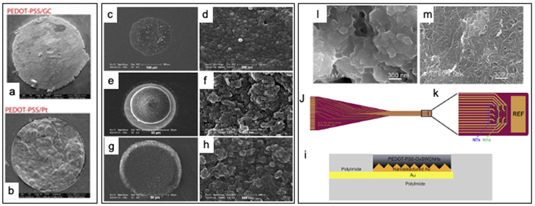
(a) Scanning electron microscopy of PEDOT-PSS on GC substrate after 5 million pulses vs. (b) scanning electron microscopy of PEDOT-PSS on Pt substrate after 1 million pulses of stimulation. Note the crack formation in PEDOT-PSS/Pt due to poor adhesion in (b). Adapted from [166] with permission. (c-h) PEDOT/CNT polymerized on Pt substrate with potentiostatic method and galvanic method respectively. Potentiostatically polymerized coating resulted in a relatively flatter surface d) and exceeded the bounds of the underlying substrate whereas in (e) the galvanostatically polymerized PEDOT/CNT formed a 3D cone shape with increased porosity (f). (g-h) SEM of the same substrate coated with PEDOT-PSS for reference. Adapted from [174] with permission.(i-m) polyimide-based electrode with gold traces was patterned with nanostructured gold polymerized with PEDOT/ox-SWCNH and PEDOT ox-MWCNT. NTs: nanotubes, NH: nanohorns (j-k). (I,m) Nanoporous morphology of NHs and NTs respectively. Adapted from [176] with permission.
6.2.2. Drug delivery to improve stimulation stability
Unlike traditional metals, the unique properties of CPs enable the incorporation of drugs that may be beneficial for decreasing tissue inflammation while improving the stability at the electrode-tissue interface. Dexamethasone(Dex) is an anti-inflammatory steroid that reduces inflammation.[177] It can be electrochemically released from the bulk of the conducting polymer using CVs.[178, 179] The drug loading capacity of CPs can be further improved by doping the polymer with nano drug carriers, such as CNTs,[180] graphene oxide[181] and nanoparticles for targeted and on-demand drug delivery.[182] Kolarcik et al stimulated the dorsal root ganglion with electrodes coated with PEDOT co-doped with CNTs and Dex. Electrical stimulation was delivered for 1 hour per day for 10 days using biphasic pulses consisting of 20 μA of 200 μs cathodic phase and 400 μs anodic phase with half the amplitude. PEDOT/CNT/Dex coated electrodes showed significantly less neuronal death compared to non-coated electrodes.[24] Woeppel et al doped PEDOT with sulfonate modified particles (SNP).
The selective inclusion of hexadecyltrimethylammonium bromide (CTAB) allows for the creation of porous and non-porous SNPs. non-porous SNP doped PEDOT films had significantly lower interfacial impedance than PEDOT/PSS of the same dimensions, high CIL (4.8 mC cm−2) and are significantly more stable than PEDOT/PSS under 24 hours of stimulation at 85% CIL at 50 Hz (4.32 million pulses). Porous SNPs enable the loading of various drugs that may be otherwise sensitive to electrochemical reactions or possess positive ions making it unsuitable as the lone dopant for PEDOT. The authors demonstrated successful release of doxorubicin and melatonin and their maintained bioactivity in the released environment. Additionally, successful suppression of neuron activity via the release of DNQX in the cortex of GCAMP6s mice was demonstrated in vivo.[182]
7. Carbon Materials
Carbon materials offer intriguing properties for electrical micro-stimulation, such as electrochemical stability, capacitive electrochemical behavior, wide electrochemical window, and fast electron transfer kinetics,[18, 166] combined with chemical inertness and biocompatibility.[166] Glassy carbon (GC) electrodes have more than 70% wider electrochemical window and 70% higher CSC than Pt microelectrodes of similar geometry.[166] Furthermore, they demonstrated a purely capacitive behavior with exceptional stability over prolonged electrical stimulation in vitro.[18, 186] sustaining more than 3.5 billion cycles of bi-phasic pulses at a charge density of 0.25 mC cm−2 without failure.[18] However, smooth carbon materials, such as the flat surface of GC flat surface or 2D graphene, present relatively high impedance and low charge storage capacity compared to high surface area coatings, and this factor can limit miniaturization. Therefore, high-surface area carbon-based nanomaterials, including carbon nanotube (CNT),[27] and porous graphene,[29] [187] [28] that combine the properties of carbon with a high surface area, are considered very attractive and have been investigated for microstimulation.[27, 188]
Table 4 provides a summary of the most recent development in stimulating electrodes using carbon-based materials.
Vertically aligned multiwalled CNT pillar microelectrode arrays, synthetized by thermal chemical vapor deposition (CVD) presented a relatively high CIL of 1–1.6 mC cm−2, without faradic reactions, and have been demonstrated to be effective in electrical stimulation of primary neurons.[188] (Figure 4a). Fluffy CNT directly synthesized by CVD on the tip of sharp metal microelectrodes (Figure 4b) showing a superior electrochemical stability to electropolymerized CNT nanocomposite coatings through direct comparison on similar microelectrodes.[27] Thanks to the larger exposed CNT morphology, they presented a CIL of 4 mC cm−2, superior to that previously reported for vertical pillars [188], and they withstand a million pulses without any degradation, while all of the other coatings (PPy-CNT and Au-CNT) showed different degrees of impedance variation after stimulation.[27] Nevertheless, CNT synthesis via CVD is not always selective to the microelectrode sites and usually requires very high temperatures (> 650 °C) that polymer substrates cannot withstand.[27] Additionally, the catalysts used for CVD, such as nickel, iron, cobalt, and copper, are potentially cytotoxic if not completely removed.[27, 190–192] These limitations do not enable fabrication scalability, and, despite some promising attempts,[27, 193, 194] the acute and long-term performance of these CNT microelectrodes in vivo has not yet been demonstrated.
Figure 4.

a) Vertically aligned multiwalled CNT pillars microelectrode arrays (left) and magnification on a single pillars microelectrode (right). From [188]. b) Scanning electron microscopy images of microelectrodes coated with carbon nanotubes grown by chemical vapor deposition. From [27]. c) Scanning electron microscopy imaging of two-channel CNT fiber microelectrodes, fabricated by twisting single filaments of a 43 μm diameter CNT fiber, coated with a 3 μm layer of PS-b-PBD; inset shows a close view of the active site. From [189]. d) GF fibers from [29]: picture of a GF bipolar microelectrode assembly. Inset, SEM image of the GF bipolar microelectrode tip, showing two GFs (bright core) with each one insulated with Parylene-C film (dark shell). Scale bar, 1 cm; inset, 100 μm (left). SEM image of the axial external surface of a GF fiber. Inset, magnified image of the region in the dashed box. Scale bar, 20 μm; inset, 5 μm. (center). SEM image of the exposed cross section acting as the active stimulating site of a GF electrode. Inset, magnified image of the region in the dashed box. Scale bar, 20 μm; inset, 5 μm (right). From [29]. e) liquid crystal graphene oxide (LCGO) fiber with parylene-C insulation: electrode pressed into clay to demonstrate flexibility and elastic deformation (left). Laser treatment leads to an amorphous electrode with extraordinary surface roughness and porosity (right). From [187]
Carbon fiber microelectrodes (CFEs)[195] and CFE arrays[196–200] have demonstrated promising results in seamless electrode tissue interface with markedly reduced immune response due to the subcellular size of each fiber (~7 μm). Indeed, the small feature size of CFE is similar to the size of a single trace of a conventional silicon neural probe, but they are sufficiently robust and flexible as a stand-alone electrode. For example, single CFEs with paryelne C insulation and PEDOT:PSS recording site, have been used as subcellular-scale probes for electrophysiological recordings, demonstrating promising results in chronic in vivo recordings [195]. Furthermore, these micro-invasive probes provided stable monitoring of sub-second evoked DA fluctuations in rats for over a year [201] and in non-human primates for over 100 days [198]. However, due to the smooth surface of the carbon fiber, CFEs require low impedance coating such as PEDOT:PSS, [195] PEDOT/pTS,[202], or electrodeposited Pt/Ir [202] to enable high SNR recordings and their CIL is insufficient for stimulation (0.05 mC cm−2).[29] CNT fibers (18μm diameter, Figure 4c), consisting of bulk-grown CNTs, have been produced by high-throughput wet spinning, and then individually insulated with a ~3 μm layer of a copolymer of polystyrene–polybutadiene (PS-b-PBD), leaving only the tip exposed. The resulting electrically active sites, due to the porous surface area, have shown remarkable electrochemical properties, i.e., low impedance (ca. 1.410 kΩ, GSA: 1450 μm2), wide water window (−1.5 to 1.5 V), high CIL (6.5 mC cm−2), [189] and excellent electrochemical stability under prolonged current pulsing (97M cycles beyond the water window limits).[189] In vivo, CNT fiber microelectrodes were demonstrated to be able to deliver efficacious DBS in a Parkinsonian rat model and presented a superior biocompatibility in comparison to PtIr microwires implanted in the same animals for 6 weeks.[189] This study highlighted the promising potential of using CNT fiber for effective long-term stimulation use. Additionally, in the same study, CNT fibers have been successfully used to record stable neural activity for weeks, showing potentiality for bidirectional access to the brain. However, as mentioned before, common CNT production and fiber assembly via wet spinning are laborious and involves the use of metal catalysts, limiting the widespread use. A dry spinning method which directly synthesizes CNT arrays free of catalyst may eliminate this concern. Further, the dry spun CNT fibers can be assembled at up to 16 m s−1 linear speed, offering great potential for mass production. The proof of concept dry-spun CNT fiber arrays (CIL:15.09 mC cm−2) for neural stimulation in Madagascar hissing cockroach has been demonstrated recently,[203] motivating future testing for long-term stimulation performance in higher order animal models.
Similarly, porous graphene fibers (GF, ~75 μm diameter)[29] have been prepared through a dimension-confined hydrothermal process from aqueous graphite oxide (GO) suspensions, and then individually insulated with parylene-C film of ~5 μm thickness (Figure. 6d). They have a wide water window of −1.5 to 1.3 V, a CIL of 10.1 mC cm−2, capacitive charging/discharging mechanism, and excellent electrochemical stability under overcurrent pulsing (total of 205.2 M pulses, 19 days).[29] In vivo, these fibers microelectrodes demonstrated the capability for efficacious DBS in hemi-Parkinsonian rats, verified during artifact-free MRI image acquisition.[29] The high charge-injection-capacity of the GF electrodes enabled the use of relatively small electrodes without compromising the stimulation efficacy, important for maintaining a small artifact size of the MRI and providing high selectivity and spatial resolution of microstimulation (Figure 4e).[29] Graphene fibers have also been fabricated using wet spinning of graphene oxide (GO) liquid crystal phases,[187, 204] also in this case, they presented highly porous surface area, high CIL, low impedance and have been used to stimulate live retina in vitro (Figure 4f).[187]
A common issue for carbon, CNT and graphene fiber is that current methods of assembling fibers into multielectrode arrays is semi-manual and does not permit reproducible high-density 3D microelectrode array configuration or production scale up. The promising micro-stimulation performance and stability of porous carbon materials present an urgent need to develop scalable synthesis and fabrication process for carbon-based MEAs. While growing porous carbon on metal electrode sites had demonstrated the benefit of carbon, the bonding between porous carbon and the underlying metal may be prone to delamination under repeated stimulation or mechanical bending due to the electrical and mechanical mismatch. Additionally, the high temperature required for the synthesis of carbon and nanocarbon limits the choice of the substrate materials, making patterning nanocarbon materials on multi-channel large scale configurations on flexible substrate extremely challenging.[27, 205]. Thus, most demonstrations have been performed on single wire penetrating electrodes [27] or in vitro non implantable MEAs on silicon wafers [188].
The best scenario may be to fabricate carbon based MEAs that integrates high density carbon microelectrode arrays and interconnections on flexible polymeric substrates, eliminating the mismatched layers, such as intermediate adhesion of conductive metal layers. This possibility will remove the sources of potential mechanical or electrical discontinuities and failure under prolonged electrical and mechanical solicitations, improving the microstimulation performance together with the device biocompatibility.
There have been recent attempts to develop microfabrication techniques to yield arrays of carbon electrodes on flexible substrate for microstimulation applications. These attempts use the pattern transfer technique of pre-pyrolyzed GC microelectrodes on polyimide substrates (Figure 5a,b),[18, 186, 206] direct laser pyrolysis of porous graphene on polyimide substrate (Figure 5d–f),[28] or laser carbonization of parylene C (Figure 5c).[207] As previously mentioned, GC shows outperforming properties compared with Pt microelectrodes of similar geometry in terms of electrochemical stability.[166] The GC microelectrodes have been recently miniaturized and GC MEA intracortical probes demonstrated the capability to record high quality single-unit neural activity and to detect low dopamine concentrations in vitro and in vivo,[18, 206, 208, 209] offering great promise for multimodal interaction with the brain. Besides glassy carbon, porous graphene electrodes obtained by laser pyrolysis and subsequent doping with nitric acid exhibited a CIL of 3.1 mC cm−2 and very low impedance (519 Ω at 1 kHz for 250 μm diameter electrodes), which remained relatively stable in PBS solution over 28 days, and showing no physical degradation after 1 million cycles.[28] Additionally, graphitic carbon obtained by inducing the laser carbonization of parylene C on top of robust metal sheets (e.g., platinum/iridium tracks) has maintained stability by aging in 30 mM H2O2 for one week, or by 10 million pulse (biphasic, 39.5 μC cm−2) of electrical stimulation.[207] To date, laser pyrolysis fabrication has been reported only for micro-ECoG devices with relatively big electrodes (200-700μm diameter).[207] Indeed, the main limitation of this technology is the laser resolution which needs to be drastically improved for miniaturization and high-density arrays.
Figure 5.
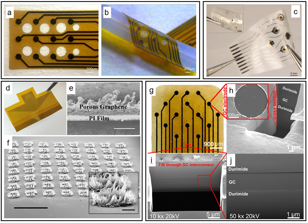
(a) GC 12 electrode array and (b) the device is folded to show its flexibility. From [166]. (c) 9-electrode array (curled in the inset) From[207]. (d) Photograph of a fabricated 64 porous graphene electrode array. (e) SEM image of the cross-section view of porous graphene. Scale bar:100 μm. (f) Tilt SEM image of a 64-spot porous graphene array. Scale bar: 1mm. The inset is the SEM image of an individual spot. Scale bar: 100 μm. From [28]. (g)15-channel GC ECoG probe, (h) In inset: Magnified SEM image of a single microelectrode in the ECoG probe. Also, FIB cross-section of the GC microelectrode taken at the edge between GC and Durimide is shown revealing a seamless integration of the layers. (i) Expanded view of FIB cross-section taken at a GC wire trace leading to one of the microelectrodes, (j) High-resolution (50,000×) FIB image of a cross-section taken through a GC wire trace. Box in bottom of (i) shows the location where FIB through GC interconnect was taken. Note that there are no adhesion layers or metal layers in all GC (aGC) probes. From [18]
Most of these mentioned MEAs use metal interconnections, which present mechanical and electrical mismatch issues between the metal interconnections and the carbon electrodes under prolonged electrical stimulation and mechanical stresses. To the best of our knowledge, there is only one case of a microfabricated MEA that uses GC for the microelectrodes, traces, and bonding pads, made by a single and homogeneous GC material integrated on a flexible polyimide substrate (Figure 5g–j). These all-GC probes were fabricated using a double-sided 2-step lithographic technique that allows transferring pre-patterned GC structures into a polymeric substrate and insulation layers.[18] Other than recording and sensing capability, these MEAs demonstrated to be capable of delivering charge-balance current pulsing over 3.5 billion cycles in extended accelerated aging process lasting more than 1000 hours, without failure at the GC and polyimide interface.[18] This study suggests a stronger electrochemical and mechanical robustness of probes made from a single carbon material without any metal interconnection or surface coating and encourage the investigation of new and simplified technique for the scale up and batch-fabrication of all-carbon devices.
Looking into this direction, the optimization of laser technique would allow for fast, low-cost batch-fabrication of patterned microelectrode arrays and conducting traces on free-standing polymeric films, without the need of high-temperature carbon synthesis, such as pyrolysis or chemical vapor deposition, or multistep photolithographic microfabrication processes. Furthermore, a localized rapid heating by laser rastering can potentially enable a precise control of the atomic structure, nanoscale morphology, and micron-scale geometry of nanocarbon microelectrodes, opening the door for unprecedented ability to tune and optimize the morphology and performance of nanocarbon MEAs.
8. Future perspective
Chronically stable stimulating neural interfaces require a coordinated effort from an interdisciplinary team of neuroscientists, material scientists and engineers. Despite improved charge injection limit in novel metal/metal oxides, conducting polymers, and carbon-based materials, devices made from these materials still face challenges similar to those encountered by recording electrodes. In stimulating devices, it is imperative to ensure insulation integrity, electrode coating adhesion, and mechanical stability of connectors to external data acquisition units. Numerous existing technologies could be combined to solve issues of foreign body responses and oxidative stress as a result of implantation. Surface modification with bioactive and biomimetic molecules such as neural adhesion molecules L1, anti-inflammatory peptides, super hydrophilic coatings and superoxide dismutase or delivery of antioxidant and anti-inflammatory drugs have shown to reduce microglia activation,[211] neuronal death,[212] astrocytic scars,[212] improve axonal regrowth,[212] and reduce the generation of ROS at the vicinity of the implants.[118] While more neural electrodes are fabricated with subcellular dimensions and ultra-flexibility, investigations of microstimulation efficacy and stability on these devices need to be performed with particular attention on the dynamic electrochemical properties that accompany flexible electronics.[85, 213] Finally, we should use advanced genetic and imaging tools to understand the effects of electrical stimulation on both neuronal [130]and non-neuronal cells in order to understand the mechanism of electrical stimulation and optimize stimulation parameters for different applications. As with all newly developed medical devices, the road to clinical translation will be long. We must be aware of the regulatory process [214, 215] and be in compliance with the FDA guidelines to ensure ultimate safety from a material perspective and the design of safe stimulation paradigms.
References:
- [1].Yeomans JS, Frankland PW, Brain research reviews 1995, 21, 301. [DOI] [PubMed] [Google Scholar]
- [2].Tehovnik EJ, Slocum WM, Schiller PH, European Journal of Neuroscience 2004, 20, 264. [DOI] [PubMed] [Google Scholar]
- [3].Strick PL, Preston JB, Brain research 1978, 154, 366. [DOI] [PubMed] [Google Scholar]
- [4].Schmidt E, Bak M, Hambrecht F, Kufta C, O’rourke D, Vallabhanath P, Brain 1996, 119, 507. [DOI] [PubMed] [Google Scholar]
- [5].McCreery D, Yuen T, Bullara L, Hearing Research 2000, 149, 223. [DOI] [PubMed] [Google Scholar]
- [6].Mushahwar VK, Gillard DM, Gauthier MJ, Prochazka A, IEEE Transactions on Neural Systems and Rehabilitation Engineering 2002, 10, 68. [DOI] [PubMed] [Google Scholar]
- [7].Flesher SN, Collinger JL, Foldes ST, Weiss JM, Downey JE, Tyler-Kabara EC, Bensmaia SJ, Schwartz AB, Boninger ML, Gaunt RA, Science translational medicine 2016, 8, 361ra141. [DOI] [PubMed] [Google Scholar]
- [8].Rogers R, Hermann G, Journal of the autonomic nervous system 1985, 14, 351. [DOI] [PubMed] [Google Scholar]
- [9].Guo J, Jin H, Shi Z, Yin J, Pasricha T, Chen JD, Neurogastroenterology & Motility 2019, 31, e13676. [DOI] [PubMed] [Google Scholar]
- [10]., 2020, 200.
- [11].Kelly SK, Shire DB, Chen J, Doyle P, Gingerich MD, Cogan SF, Drohan WA, Behan S, Theogarajan L, Wyatt JL, Rizzo JF 3rd, IEEE transactions on bio-medical engineering 2011, 58, 3197. [DOI] [PMC free article] [PubMed] [Google Scholar]
- [12].Cogan SF, Annual Review of Biomedical Engineering 2008, 10, 275. [DOI] [PubMed] [Google Scholar]
- [13].Arcot Desai S, Gutekunst CA, Potter SM, Gross RE, Front Neuroeng 2014, 7, 16. [DOI] [PMC free article] [PubMed] [Google Scholar]
- [14].Weiland J, Fink W, Humayun M, Liu W, Rodger D, Tai YC, Tarbell M, Conf Proc IEEE Eng Med Biol Soc 2005, 2005, 7373. [DOI] [PubMed] [Google Scholar]
- [15].Cogan SF, Ehrlich J, Plante TD, Smirnov A, Shire DB, Gingerich M, Rizzo JF, Journal of Biomedical Materials Research Part B: Applied Biomaterials 2009, 89B, 353. [DOI] [PMC free article] [PubMed] [Google Scholar]
- [16].Cogan SF, Troyk PR, Ehrlich J, Plante TD, Detlefsen DE, IEEE Transactions on Biomedical Engineering 2006, 53, 327. [DOI] [PubMed] [Google Scholar]
- [17].Weiland JD, Anderson DJ, Humayun MS, IEEE transactions on biomedical engineering 2002, 49, 1574. [DOI] [PubMed] [Google Scholar]
- [18].Nimbalkar S, Castagnola E, Balasubramani A, Scarpellini A, Samejima S, Khorasani A, Boissenin A, Thongpang S, Moritz C, Kassegne S, Scientific reports 2018, 8, 1. [DOI] [PMC free article] [PubMed] [Google Scholar]
- [19].Boehler C, Vieira DM, Egert U, Asplund M, ACS Applied Materials & Interfaces 2020, 12, 14855. [DOI] [PubMed] [Google Scholar]
- [20].Aqrawe Z, Montgomery J, Travas-Sejdic J, Svirskis D, Sensors and Actuators B: Chemical 2018, 257, 753. [Google Scholar]
- [21].Wilks SJ, Richardson-Burn SM, Hendricks JL, Martin D, Otto KJ, Frontiers in neuroengineering 2009, 2, 7. [DOI] [PMC free article] [PubMed] [Google Scholar]
- [22].Cui XT, Zhou DD, IEEE Trans Neural Syst Rehabil Eng 2007, 15, 502. [DOI] [PubMed] [Google Scholar]
- [23].Luo X, Weaver CL, Zhou DD, Greenberg R, Cui XT, Biomaterials 2011, 32, 5551. [DOI] [PMC free article] [PubMed] [Google Scholar]
- [24].Kolarcik CL, Catt K, Rost E, Albrecht IN, Bourbeau D, Du Z, Kozai TDY, Luo X, Weber DJ, Tracy Cui X, Journal of Neural Engineering 2014, 12, 016008. [DOI] [PMC free article] [PubMed] [Google Scholar]
- [25].Zeng Q, Xia K, Sun B, Yin Y, Wu T, Humayun MS, Electrochimica Acta 2017, 237, 152. [Google Scholar]
- [26].Fierro S, Kapałka A, Comninellis C, Electrochemistry communications 2010, 12, 172. [Google Scholar]
- [27].Ansaldo A, Castagnola E, Maggiolini E, Fadiga L, Ricci D, ACS nano 2011, 5, 2206. [DOI] [PubMed] [Google Scholar]
- [28].Lu Y, Lyu H, Richardson AG, Lucas TH, Kuzum D, Scientific reports 2016, 6, 33526. [DOI] [PMC free article] [PubMed] [Google Scholar]
- [29].Zhao S, Li G, Tong C, Chen W, Wang P, Dai J, Fu X, Xu Z, Liu X, Lu L, Nature communications 2020, 11, 1. [DOI] [PMC free article] [PubMed] [Google Scholar]
- [30].Bullard AJ, Hutchison BC, Lee J, Chestek CA, Patil PG, Neuromodulation: Technology at the Neural Interface 2020, 23, 411. [DOI] [PubMed] [Google Scholar]
- [31].Salatino JW, Ludwig KA, Kozai TDY, Purcell EK, Nature Biomedical Engineering 2017, 1, 862. [DOI] [PMC free article] [PubMed] [Google Scholar]
- [32].Polikov VS, Tresco PA, Reichert WM, Journal of Neuroscience Methods 2005, 148, 1. [DOI] [PubMed] [Google Scholar]
- [33].Kozai TD, Gugel Z, Li X, Gilgunn PJ, Khilwani R, Ozdoganlar OB, Fedder GK, Weber DJ, Cui XT, Biomaterials 2014, 35, 9255. [DOI] [PubMed] [Google Scholar]
- [34].Kozai TDY, Vazquez AL, Weaver CL, Kim S-G, Cui XT, Journal of neural engineering 2012, 9, 066001. [DOI] [PMC free article] [PubMed] [Google Scholar]
- [35].Merrill DR, Bikson M, Jefferys JG, Journal of neuroscience methods 2005, 141, 171. [DOI] [PubMed] [Google Scholar]
- [36].Wright SH, Advances in physiology education 2004, 28, 139. [DOI] [PubMed] [Google Scholar]
- [37].Kole MH, Stuart GJ, Nature neuroscience 2008, 11, 1253. [DOI] [PubMed] [Google Scholar]
- [38].Yuk H, Lu B, Zhao X, Chemical Society Reviews 2019, 48, 1642. [DOI] [PubMed] [Google Scholar]
- [39].Martin DC, Malliaras GG, ChemElectroChem 2016, 3, 686. [Google Scholar]
- [40].Cogan SF, Ludwig KA, Welle CG, Takmakov P, J Neural Eng 2016, 13, 021001. [DOI] [PMC free article] [PubMed] [Google Scholar]
- [41].Boehler C, Carli S, Fadiga L, Stieglitz T, Asplund M, Nature Protocols 2020, 15, 3557. [DOI] [PubMed] [Google Scholar]
- [42].Lu Y, Wang T, Cai Z, Cao Y, Yang H, Duan YY, Sensors and Actuators B: Chemical 2009, 137, 334. [Google Scholar]
- [43].Rose TL, Robblee LS, IEEE Transactions on Biomedical Engineering 1990, 37, 1118. [DOI] [PubMed] [Google Scholar]
- [44].Mahadevappa M, Weiland JD, Yanai D, Fine I, Greenberg RJ, Humayun MS, IEEE Transactions on Neural Systems and Rehabilitation Engineering 2005, 13, 201. [DOI] [PubMed] [Google Scholar]
- [45].Rizzo JF, Wyatt J, Loewenstein J, Kelly S, Shire D, Investigative ophthalmology & visual science 2003, 44, 5362. [DOI] [PubMed] [Google Scholar]
- [46].Hambrecht F, Bailliere’s clinical neurology 1995, 4, 147. [PubMed] [Google Scholar]
- [47].Günter C, Delbeke J, Ortiz-Catalan M, Journal of neuroengineering and rehabilitation 2019, 16, 1. [DOI] [PMC free article] [PubMed] [Google Scholar]
- [48].Agnew WF, McCreery DB, Yuen TG, Bullara LA, Annals of biomedical engineering 1989, 17, 39. [DOI] [PubMed] [Google Scholar]
- [49].Zheng XS, Yang Q, Vazquez A, Cui XT, Advanced NanoBiomed Research n/a, 2000092. [DOI] [PMC free article] [PubMed] [Google Scholar]
- [50].McCreery DB, Yuen TG, Agnew WF, Bullara LA, IEEE Trans Biomed Eng 1997, 44, 931. [DOI] [PubMed] [Google Scholar]
- [51].Tykocinski M, Shepherd RK, Clark GM, Hearing research 1997, 112, 147. [DOI] [PubMed] [Google Scholar]
- [52].Pudenz RH, Bullara L, Dru D, Talalla A, Surgical neurology 1975, 4, 265. [PubMed] [Google Scholar]
- [53].Pudenz R, Bullara LA, Jacques S, Hambrecht F, Surgical Neurology 1975, 4, 389. [PubMed] [Google Scholar]
- [54].Mortimer JT, Shealy CN, Wheeler C, Journal of neurosurgery 1970, 32, 553. [DOI] [PubMed] [Google Scholar]
- [55].Chan PH, Yurko M, Fishman RA, Journal of neurochemistry 1982, 38, 525. [DOI] [PubMed] [Google Scholar]
- [56].Buettner GR, Archives of biochemistry and biophysics 1993, 300, 535. [DOI] [PubMed] [Google Scholar]
- [57].Chia L, Thompson J, Moscarello M, Biochemical and biophysical research communications 1983, 117, 141. [DOI] [PubMed] [Google Scholar]
- [58].Griot C, Vandevelde M, Richard A, Peterhans E, Free radical research communications 1990, 11, 181. [DOI] [PubMed] [Google Scholar]
- [59].Konat GW, Wiggins RC, Journal of neurochemistry 1985, 45, 1113. [DOI] [PubMed] [Google Scholar]
- [60].Sevanian A, in Cellular antioxidant defense mechanisms, Vol. 2, CRC Press; Boca Raton, FL: 1988, p. 78. [Google Scholar]
- [61].McCreery D, Pikov V, Troyk PR, Journal of neural engineering 2010, 7, 036005. [DOI] [PMC free article] [PubMed] [Google Scholar]
- [62].Chen KH, Dammann JF, Boback JL, Tenore FV, Otto KJ, Gaunt RA, Bensmaia SJ, Journal of Neural Engineering 2014, 11, 026004. [DOI] [PMC free article] [PubMed] [Google Scholar]
- [63].Rajan AT, Boback JL, Dammann JF, Tenore FV, Wester BA, Otto KJ, Gaunt RA, Bensmaia SJ, Journal of neural engineering 2015, 12, 066018. [DOI] [PMC free article] [PubMed] [Google Scholar]
- [64].Park E, Lyon JG, Alvarado-Velez M, Betancur MI, Mokarram N, Shin JH, Bellamkonda RV, Journal of neuroscience research 2021. [DOI] [PMC free article] [PubMed] [Google Scholar]
- [65].Carbonario F, Matsutani L, Yuan S, Marques A, European journal of physical and rehabilitation medicine 2013, 49, 197. [PubMed] [Google Scholar]
- [66].Hahm S-C, Yoon YW, Kim J, Neurorehabilitation and neural repair 2015, 29, 370. [DOI] [PubMed] [Google Scholar]
- [67].Negi S, Bhandari R, Rieth L, Van Wagenen R, Solzbacher F, Journal of Neuroscience Methods 2010, 186, 8. [DOI] [PMC free article] [PubMed] [Google Scholar]
- [68].Ohayon S, Grimaldi P, Schweers N, Tsao DY, J Neurosci 2013, 33, 16684. [DOI] [PMC free article] [PubMed] [Google Scholar]
- [69].Ni AM, Maunsell JH, Current Biology 2010, 20, 824. [DOI] [PMC free article] [PubMed] [Google Scholar]
- [70].Vallejo R, Gupta A, Kelley CA, Vallejo A, Rink J, Williams JM, Cass CL, Smith WJ, Benyamin R, Cedeño DL, Neuromodulation 2020, 23, 26. [DOI] [PubMed] [Google Scholar]
- [71].Rousche PJ, Normann RA, IEEE transactions on rehabilitation engineering 1999, 7, 56. [DOI] [PubMed] [Google Scholar]
- [72].Bartlett JR, Doty sr RW, Lee BB, Negrão N, Overman jr WH, Brain, behavior and evolution 1977, 14, 46. [DOI] [PubMed] [Google Scholar]
- [73].Chowdhury SA, DeAngelis GC, Neuron 2008, 60, 367. [DOI] [PMC free article] [PubMed] [Google Scholar]
- [74].Law C-T, Gold JI, Nature neuroscience 2009, 12, 655. [DOI] [PMC free article] [PubMed] [Google Scholar]
- [75].Kozai TD, Catt K, Li X, Gugel ZV, Olafsson VT, Vazquez AL, Cui XT, Biomaterials 2015, 37, 25. [DOI] [PMC free article] [PubMed] [Google Scholar]
- [76].Prasad A, Xue Q-S, Sankar V, Nishida T, Shaw G, Streit WJ, Sanchez JC, Journal of neural engineering 2012, 9, 056015. [DOI] [PubMed] [Google Scholar]
- [77].Caldwell R, Street MG, Sharma R, Takmakov P, Baker B, Rieth L, Biomaterials 2020, 232, 119731. [DOI] [PubMed] [Google Scholar]
- [78].Schmitt G, Faßbender F, Lüth H, Schöning MJ, Schultze JW, Buß G, Materials and Corrosion 2000, 51, 20. [Google Scholar]
- [79].Aceros J, Yin M, Borton DA, Patterson WR, Bull C, Nurmikko AV, presented at 2012 Annual International Conference of the IEEE Engineering in Medicine and Biology Society 2012. [DOI] [PMC free article] [PubMed] [Google Scholar]
- [80].Vanhoestenberghe A, Donaldson N, Journal of neural engineering 2013, 10, 031002. [DOI] [PubMed] [Google Scholar]
- [81].Prasad A, Xue Q-S, Dieme R, Sankar V, Mayrand R, Nishida T, Streit WJ, Sanchez JC, Frontiers in neuroengineering 2014, 7, 2. [DOI] [PMC free article] [PubMed] [Google Scholar]
- [82].Geddes LA, Roeder R, Annals of biomedical engineering 2003, 31, 879. [DOI] [PubMed] [Google Scholar]
- [83].White RL, Gross TJ, IEEE Transactions on Biomedical Engineering 1974, BME-21, 487. [Google Scholar]
- [84].Cogan SF, Plante T, Ehrlich J, presented at The 26th Annual International Conference of the IEEE Engineering in Medicine and Biology Society 2004. [Google Scholar]
- [85].Schiavone G, Kang X, Fallegger F, Gandar J, Courtine G, Lacour SP, Neuron 2020, 108, 238. [DOI] [PubMed] [Google Scholar]
- [86].Boehler C, Carli S, Fadiga L, Stieglitz T, Asplund M, Nature Protocols 2020, DOI: 10.1038/s41596-020-0389-2. [DOI] [PubMed] [Google Scholar]
- [87].Cisnal A, Fraile J-C, Pérez-Turiel J, Muñoz-Martinez V, Müller C, R Ihmig F, Sensors 2018, 18, 4152. [DOI] [PMC free article] [PubMed] [Google Scholar]
- [88].Morton SL, Daroux ML, Mortimer JT, Journal of The Electrochemical Society 1994, 141, 122. [Google Scholar]
- [89].Leung RT, Shivdasani MN, Nayagam DA, Shepherd RK, IEEE Transactions on Biomedical Engineering 2014, 62, 849. [DOI] [PubMed] [Google Scholar]
- [90].Cisnal A, R Ihmig F, Fraile J-C, Pérez-Turiel J, Muñoz-Martinez V, Sensors 2019, 19, 2725. [DOI] [PMC free article] [PubMed] [Google Scholar]
- [91].Ganji M, Tanaka A, Gilja V, Halgren E, Dayeh SA, Advanced Functional Materials 2017, 27, 1703019. [Google Scholar]
- [92].Vomero M, Oliveira A, Ashouri D, Eickenscheidt M, Stieglitz T, Scientific Reports 2018, 8, 14749. [DOI] [PMC free article] [PubMed] [Google Scholar]
- [93].Geninatti T, Bruno G, Barile B, Hood RL, Farina M, Schmulen J, Canavese G, Grattoni A, Biomedical microdevices 2015, 17, 24. [DOI] [PMC free article] [PubMed] [Google Scholar]
- [94].ASTM D3359-17. www.astm.org
- [95].Goding JA, Gilmour AD, Martens PJ, Poole-Warren LA, Green RA, Journal of Materials Chemistry B 2015, 3, 5058. [DOI] [PubMed] [Google Scholar]
- [96].Castagnola E, Carli S, Vomero M, Scarpellini A, Prato M, Goshi N, Fadiga L, Kassegne S, Ricci D, Biointerphases 2017, 12, 031002. [DOI] [PubMed] [Google Scholar]
- [97].Duan S, Zhang L, Wang Z, Li C, RSC Advances 2015, 5, 95280. [Google Scholar]
- [98].Castagnola E, Maiolo L, Maggiolini E, Minotti A, Marrani M, Maita F, Pecora A, Angotzi GN, Ansaldo A, Boffini M, Fadiga L, Fortunato G, Ricci D, IEEE Transactions on Neural Systems and Rehabilitation Engineering 2015, 23, 342. [DOI] [PubMed] [Google Scholar]
- [99].Hukins D, Mahomed A, Kukureka S, Medical engineering & physics 2008, 30, 1270. [DOI] [PubMed] [Google Scholar]
- [100].Lambert BJ, Tang F-W, Radiation Physics and Chemistry 2000, 57, 349. [Google Scholar]
- [101].ASTM. International, DOI: 10.1520/F1980-16, www.astm.org 2016. [DOI] [Google Scholar]
- [102].Takmakov P, Ruda K, Scott Phillips K, Isayeva IS, Krauthamer V, Welle CG, J Neural Eng 2015, 12, 026003. [DOI] [PMC free article] [PubMed] [Google Scholar]
- [103].Duan YY, Clark GM, Cowan RS, presented at Smart Structures and Devices 2001. [Google Scholar]
- [104].Karp FB, Bernotski NA, Valdes TI, Bohringer KF, Ratner BD, IEEE Sensors Journal 2008, 8, 104. [Google Scholar]
- [105].Williams JC, Hippensteel JA, Dilgen J, Shain W, Kipke DR, Journal of neural engineering 2007, 4, 410. [DOI] [PubMed] [Google Scholar]
- [106].Straka MM, Shafer B, Vasudevan S, Welle C, Rieth L, Micromachines (Basel) 2018, 9, 587. [DOI] [PMC free article] [PubMed] [Google Scholar]
- [107].Zhou J, Anjum DH, Chen L, Xu X, Ventura IA, Jiang L, Lubineau G, Journal of Materials Chemistry C 2014, 2, 9903. [Google Scholar]
- [108].Kuramochi Y, Guo X, Sawyer DB, Lim CC, Exp Physiol 2006, 91, 773. [DOI] [PubMed] [Google Scholar]
- [109].Allahyari Z, Haghighipour N, Moztarzadeh F, Ghazizadeh L, Hamrang M, Shokrgozar MA, Gholizadeh S, RSC Advances 2016, 6, 109902. [DOI] [PubMed] [Google Scholar]
- [110].Chen C, Bai X, Ding Y, Lee I-S, Biomaterials Research 2019, 23, 25. [DOI] [PMC free article] [PubMed] [Google Scholar]
- [111].Puiggalí-Jou A, Del Valle LJ, Alemán C, Materials (Basel) 2019, 12, 2633. [DOI] [PMC free article] [PubMed] [Google Scholar]
- [112].Green R, Matteucci P, Hassarati R, Giraud B, Dodds C, Chen S, Byrnes-Preston P, Suaning G, Poole-Warren L, Lovell N, Journal of neural engineering 2013, 10, 016009. [DOI] [PubMed] [Google Scholar]
- [113].Castagnola E, Ansaldo A, Maggiolini E, Angotzi GN, Skrap M, Ricci D, Fadiga L, ACS Nano 2013, 7, 3887. [DOI] [PubMed] [Google Scholar]
- [114].McCreery DB, Agnew WF, Yuen TGH, Bullara LA, Annals of Biomedical Engineering 1988, 16, 463. [DOI] [PubMed] [Google Scholar]
- [115].Kozai TD, Catt K, Du Z, Na K, Srivannavit O, Haque RU, Seymour J, Wise KD, Yoon E, Cui XT, IEEE Trans Biomed Eng 2016, 63, 111. [DOI] [PMC free article] [PubMed] [Google Scholar]
- [116].Kozai TDY, Jaquins-Gerstl AS, Vazquez AL, Michael AC, Cui XT, ACS Chemical Neuroscience 2015, 6, 48. [DOI] [PMC free article] [PubMed] [Google Scholar]
- [117].Zheng X, Woeppel KM, Griffith AY, Chang E, Looker MJ, Fisher LE, Clapsaddle BJ, Cui XT, Advanced Healthcare Materials 2019, 8, 1801311. [DOI] [PubMed] [Google Scholar]
- [118].Zheng XS, Snyder NR, Woeppel K, Barengo JH, Li X, Eles J, Kolarcik CL, Cui XT, Acta Biomaterialia 2019, 99, 72. [DOI] [PMC free article] [PubMed] [Google Scholar]
- [119].Bent B, Chiang C, Wang C, Lad N, Kent A, Viventi J, presented at 2019 9th International IEEE/EMBS Conference on Neural Engineering (NER), 20-23 March 2019, 2019. [Google Scholar]
- [120].Obien MEJ, Deligkaris K, Bullmann T, Bakkum DJ, Frey U, Frontiers in Neuroscience 2015, 8. [DOI] [PMC free article] [PubMed] [Google Scholar]
- [121].Takahashi S, Muramatsu S, Nishikawa J, Satoh K, Murakami S, Tateno T, IEEJ Transactions on Electrical and Electronic Engineering 2019, 14, 303. [Google Scholar]
- [122].O’Shea DJ, Shenoy KV, Journal of neural engineering 2018, 15, 026020. [DOI] [PMC free article] [PubMed] [Google Scholar]
- [123].King KW, Cusack WF, Nanivadekar AC, Ayers CA, Urbin MA, Gaunt RA, Fisher LE, Weber DJ, Journal of Neural Engineering 2019, 17, 016014. [DOI] [PMC free article] [PubMed] [Google Scholar]
- [124].Newbold C, Richardson R, Millard R, Seligman P, Cowan R, Shepherd R, Journal of neural engineering 2011, 8, 036029. [DOI] [PMC free article] [PubMed] [Google Scholar]
- [125].Gonzalez-Calle A, Weiland JD, Annu Int Conf IEEE Eng Med Biol Soc 2016, 2016, 6182. [DOI] [PMC free article] [PubMed] [Google Scholar]
- [126].Chang Y-C, Weiland JD, Int IEEE EMBS Conf Neural Eng 2017, 2017, 345. [DOI] [PMC free article] [PubMed] [Google Scholar]
- [127].Histed MH, Bonin V, Reid RC, Neuron 2009, 63, 508. [DOI] [PMC free article] [PubMed] [Google Scholar]
- [128].Michelson NJ, Eles JR, Vazquez AL, Ludwig KA, Kozai TDY, bioRxiv 2018, DOI: 10.1101/338525338525. [DOI] [Google Scholar]
- [129].Stieger KC, Eles JR, Ludwig KA, Kozai TDY, Journal of Neuroscience Research 2020, 98, 2072. [DOI] [PMC free article] [PubMed] [Google Scholar]
- [130].Eles JR, Kozai TDY, Biomaterials 2020, 234, 119767. [DOI] [PMC free article] [PubMed] [Google Scholar]
- [131].Eles JR, Vazquez AL, Kozai TDY, Cui XT, Biomaterials 2018, 174, 79. [DOI] [PMC free article] [PubMed] [Google Scholar]
- [132].Trevathan JK, Asp AJ, Nicolai EN, Trevathan JM, Kremer NA, Kozai TDY, Cheng D, Schachter MJ, Nassi JJ, Otte SL, bioRxiv 2020, 460220. [DOI] [PMC free article] [PubMed] [Google Scholar]
- [133].Kozai TDY, Eles JR, Vazquez AL, Cui XT, Journal of neuroscience methods 2016, 258, 46. [DOI] [PMC free article] [PubMed] [Google Scholar]
- [134].Lecoq J, Orlova N, Grewe BF, Journal of Neuroscience 2019, 39, 9042. [DOI] [PMC free article] [PubMed] [Google Scholar]
- [135].Jones KE, Campbell PK, Normann RA, Annals of biomedical engineering 1992, 20, 423. [DOI] [PubMed] [Google Scholar]
- [136].Ferguson M, Sharma D, Ross D, Zhao F, Advanced Healthcare Materials 2019, 8, 1900558. [DOI] [PMC free article] [PubMed] [Google Scholar]
- [137].Negi S, Bhandari R, Rieth L, Solzbacher F, Biomedical materials 2010, 5, 015007. [DOI] [PubMed] [Google Scholar]
- [138].Brunton EK, Winther-Jensen B, Wang C, Yan EB, Hagh Gooie S, Lowery AJ, Rajan R, Frontiers in neuroscience 2015, 9, 265. [DOI] [PMC free article] [PubMed] [Google Scholar]
- [139].Ghazavi A, Maeng J, Black M, Salvi S, Cogan S, Journal of neural engineering 2020, 17, 016022. [DOI] [PMC free article] [PubMed] [Google Scholar]
- [140].Chen C, Ruan S, Bai X, Lin C, Xie C, Lee I-S, Materials Science and Engineering: C 2019, 103, 109865. [DOI] [PubMed] [Google Scholar]
- [141].Peckham PH, Ackermann DM Jr, Moss CW, in Biomaterials Science, Elsevier; 2013, p. 981. [Google Scholar]
- [142].Cogan SF, Troyk PR, Ehrlich J, Plante TD, IEEE Transactions on Biomedical Engineering 2005, 52, 1612. [DOI] [PubMed] [Google Scholar]
- [143].Green RA, Matteucci PB, Hassarati RT, Giraud B, Dodds CWD, Chen S, Byrnes-Preston PJ, Suaning GJ, Poole-Warren LA, Lovell NH, Journal of Neural Engineering 2013, 10, 016009. [DOI] [PubMed] [Google Scholar]
- [144].Arreaga-Salas DE, Avendaño-Bolívar A, Simon D, Reit R, Garcia-Sandoval A, Rennaker RL, Voit W, ACS applied materials & interfaces 2015, 7, 26614. [DOI] [PubMed] [Google Scholar]
- [145].Chen Y-M, Chung T-W, Wu P-W, Chen P-C, Journal of Alloys and Compounds 2017, 692, 339. [Google Scholar]
- [146].Lu Y, Cai Z, Cao Y, Yang H, Duan YY, Electrochemistry communications 2008, 10, 778. [Google Scholar]
- [147].Cogan SF, Guzelian AA, Agnew WF, Yuen TGH, McCreery DB, Journal of Neuroscience Methods 2004, 137, 141. [DOI] [PubMed] [Google Scholar]
- [148].Meijs S, Fjorback M, Rijkhoff NJ, in Converging clinical and engineering research on neurorehabilitation, Springer; 2013, p. 421. [Google Scholar]
- [149].Steinmetz NA, Koch C, Harris KD, Carandini M, Current opinion in neurobiology 2018, 50, 92. [DOI] [PMC free article] [PubMed] [Google Scholar]
- [150].Dutta B, Andrei A, Harris T, Lopez C, O’Callahan J, Putzeys J, Raducanu B, Severi S, Stavisky S, Trautmann E, presented at 2019 IEEE International Electron Devices Meeting (IEDM) 2019. [Google Scholar]
- [151].Atmaramani R, Chakraborty B, Rihani RT, Usoro J, Hammack A, Abbott J, Nnoromele P, Black BJ, Pancrazio JJ, Cogan SF, Acta biomaterialia 2020, 101, 565. [DOI] [PMC free article] [PubMed] [Google Scholar]
- [152].Maeng J, Chakraborty B, Geramifard N, Kang T, Rihani RT, Joshi-Imre A, Cogan SF, Journal of Biomedical Materials Research Part B: Applied Biomaterials 2020, 108, 880. [DOI] [PubMed] [Google Scholar]
- [153].Deku F, Cohen Y, Joshi-Imre A, Kanneganti A, Gardner TJ, Cogan SF, Journal of neural engineering 2018, 15, 016007. [DOI] [PMC free article] [PubMed] [Google Scholar]
- [154].Cogan SF, Guzelian AA, Agnew WF, Yuen TG, McCreery DB, Journal of neuroscience methods 2004, 137, 141. [DOI] [PubMed] [Google Scholar]
- [155].Abidian MR, Corey JM, Kipke DR, Martin DC, small 2010, 6, 421. [DOI] [PMC free article] [PubMed] [Google Scholar]
- [156].Seker E, Berdichevsky Y, Begley MR, Reed ML, Staley KJ, Yarmush ML, Nanotechnology 2010, 21, 125504. [DOI] [PMC free article] [PubMed] [Google Scholar]
- [157].Nyberg T, Shimada A, Torimitsu K, Journal of neuroscience methods 2007, 160, 16. [DOI] [PubMed] [Google Scholar]
- [158].Vázquez M, Bobacka J, Ivaska A, Lewenstam A, Sensors and Actuators B: Chemical 2002, 82, 7. [Google Scholar]
- [159].Cui X, Martin DC, Sensors and Actuators B: Chemical 2003, 89, 92. [Google Scholar]
- [160].Bobacka J, Lewenstam A, Ivaska A, Journal of Electroanalytical Chemistry 2000, 489, 17. [Google Scholar]
- [161].Vara H, Collazos-Castro JE, Acta Biomaterialia 2019, 90, 71. [DOI] [PubMed] [Google Scholar]
- [162].Pranti AS, Schander A, Bödecker A, Lang W, Sensors and Actuators B: Chemical 2018, 275, 382. [Google Scholar]
- [163].Green RA, Hassarati RT, Bouchinet L, Lee CS, Cheong GL, Jin FY, Dodds CW, Suaning GJ, Poole-Warren LA, Lovell NH, Biomaterials 2012, 33, 5875. [DOI] [PubMed] [Google Scholar]
- [164].Cui X, Martin DC, Sensors and Actuators A: Physical 2003, 103, 384. [Google Scholar]
- [165].Green RA, Hassarati RT, Bouchinet L, Lee CS, Cheong GLM, Yu JF, Dodds CW, Suaning GJ, Poole-Warren LA, Lovell NH, Biomaterials 2012, 33, 5875. [DOI] [PubMed] [Google Scholar]
- [166].Vomero M, Castagnola E, Ciarpella F, Maggiolini E, Goshi N, Zucchini E, Carli S, Fadiga L, Kassegne S, Ricci D, Scientific Reports 2017, 7, 40332. [DOI] [PMC free article] [PubMed] [Google Scholar]
- [167].Bodart C, Rossetti N, Hagler JE, Chevreau P, Chhin D, Soavi F, Schougaard SB, Amzica F, Cicoira F, ACS Applied Materials & Interfaces 2019, 11, 17226. [DOI] [PubMed] [Google Scholar]
- [168].Du ZJ, Luo X, Weaver CL, Cui XT, Journal of Materials Chemistry C 2015, 3, 6515. [DOI] [PMC free article] [PubMed] [Google Scholar]
- [169].Guiseppi-Elie A, Wnek G, Le Journal de Physique Colloques 1983, 44, C3. [Google Scholar]
- [170].Clark JJ, in Perchlorate in the Environment, Springer; 2000, p. 15. [Google Scholar]
- [171].Kim S-M, Kim N, Kim Y, Baik M-S, Yoo M, Kim D, Lee W-J, Kang D-H, Kim S, Lee K, Yoon M-H, NPG Asia Materials 2018, 10, 255. [Google Scholar]
- [172].Matsumoto K, Sato C, Naka Y, Whitby R, Shimizu N, Nanotechnology 2010, 21, 115101. [DOI] [PubMed] [Google Scholar]
- [173].Chao TI, Xiang S, Chen CS, Chin WC, Nelson AJ, Wang C, Lu J, Biochem Biophys Res Commun 2009, 384, 426. [DOI] [PubMed] [Google Scholar]
- [174].Zhou H, Cheng X, Rao L, Li T, Duan YY, Acta biomaterialia 2013, 9, 6439. [DOI] [PubMed] [Google Scholar]
- [175].Tian H-C, Liu J-Q, Wei D-X, Kang X-Y, Zhang C, Du J-C, Yang B, Chen X, Zhu H-Y, NuLi Y-N, Biomaterials 2014, 35, 2120. [DOI] [PubMed] [Google Scholar]
- [176].Carli S, Lambertini L, Zucchini E, Ciarpella F, Scarpellini A, Prato M, Castagnola E, Fadiga L, Ricci D, Sensors and Actuators B: Chemical 2018, 271, 280. [Google Scholar]
- [177].Kozai TD, Jaquins-Gerstl AS, Vazquez AL, Michael AC, Cui XT, Biomaterials 2016, 87, 157. [DOI] [PMC free article] [PubMed] [Google Scholar]
- [178].Boehler C, Kleber C, Martini N, Xie Y, Dryg I, Stieglitz T, Hofmann UG, Asplund M, Biomaterials 2017, 129, 176. [DOI] [PubMed] [Google Scholar]
- [179].Alba NA, Du ZJ, Catt KA, Kozai TDY, Cui XT, Biosensors (Basel) 2015, 5, 618. [DOI] [PMC free article] [PubMed] [Google Scholar]
- [180].Luo X, Matranga C, Tan S, Alba N, Cui XT, Biomaterials 2011, 32, 6316. [DOI] [PMC free article] [PubMed] [Google Scholar]
- [181].Weaver CL, LaRosa JM, Luo X, Cui XT, ACS nano 2014, 8, 1834. [DOI] [PMC free article] [PubMed] [Google Scholar]
- [182].Woeppel KM, Zheng XS, Schulte ZM, Rosi NL, Cui XT, Advanced Healthcare Materials 2019, 8, 1900622. [DOI] [PMC free article] [PubMed] [Google Scholar]
- [183].Peixoto N, Jackson K, Samiyi R, Minnikanti S, presented at 2009 Annual International Conference of the IEEE Engineering in Medicine and Biology Society, 3-6 Sept. 2009, 2009. [DOI] [PubMed] [Google Scholar]
- [184].Du L, Li T, Jin F, Wang Y, Li R, Zheng J, Wang T, Feng Z-Q, Journal of Colloid and Interface Science 2020, 559, 65. [DOI] [PubMed] [Google Scholar]
- [185].Luo X, Weaver CL, Zhou DD, Greenberg R, Cui XT, Biomaterials 2011, 32, 5551. [DOI] [PMC free article] [PubMed] [Google Scholar]
- [186].Vomero M, Castagnola E, Ciarpella F, Maggiolini E, Goshi N, Zucchini E, Carli S, Fadiga L, Kassegne S, Ricci D, Scientific reports 2017, 7, 1. [DOI] [PMC free article] [PubMed] [Google Scholar]
- [187].Apollo NV, Maturana MI, Tong W, Nayagam DA, Shivdasani MN, Foroughi J, Wallace GG, Prawer S, Ibbotson MR, Garrett DJ, Advanced Functional Materials 2015, 25, 3551. [Google Scholar]
- [188].Wang K, Fishman HA, Dai H, Harris JS, Nano letters 2006, 6, 2043. [DOI] [PubMed] [Google Scholar]
- [189].Vitale F, Summerson SR, Aazhang B, Kemere C, Pasquali M, ACS nano 2015, 9, 4465. [DOI] [PubMed] [Google Scholar]
- [190].Losurdo M, Giangregorio MM, Capezzuto P, Bruno G, Physical Chemistry Chemical Physics 2011, 13, 20836. [DOI] [PubMed] [Google Scholar]
- [191].Murdock AT, Van Engers CD, Britton J, Babenko V, Meysami SS, Bishop H, Crossley A, Koos AA, Grobert N, Carbon 2017, 122, 207. [Google Scholar]
- [192].Terrado E, Redrado M, Munoz E, Maser W, Benito A, Martinez M, Materials Science and Engineering: C 2006, 26, 1185. [Google Scholar]
- [193].Castagnola E, Ansaldo A, Maggiolini E, Ius T, Skrap M, Ricci D, Fadiga L, Frontiers in neuroengineering 2014, 7, 8. [DOI] [PMC free article] [PubMed] [Google Scholar]
- [194].Castagnola E, Ansaldo A, Fadiga L, Ricci D, physica status solidi (b) 2010, 247, 2703. [Google Scholar]
- [195].Kozai TDY, Langhals NB, Patel PR, Deng X, Zhang H, Smith KL, Lahann J, Kotov NA, Kipke DR, Nature materials 2012, 11, 1065. [DOI] [PMC free article] [PubMed] [Google Scholar]
- [196].Patel PR, Na K, Zhang H, Kozai TD, Kotov NA, Yoon E, Chestek CA, Journal of neural engineering 2015, 12, 046009. [DOI] [PMC free article] [PubMed] [Google Scholar]
- [197].Schwerdt HN, Kim M, Karasan E, Amemori S, Homma D, Shimazu H, Yoshida T, Langer R, Graybiel AM, Cima MJ, presented at 2017 IEEE 30th International Conference on Micro Electro Mechanical Systems (MEMS) 2017. [Google Scholar]
- [198].Schwerdt HN, Shimazu H, Amemori K.-i, Amemori S, Tierney PL, Gibson DJ, Hong S, Yoshida T, Langer R, Cima MJ, Proceedings of the National Academy of Sciences 2017, 114, 13260. [DOI] [PMC free article] [PubMed] [Google Scholar]
- [199].Patel PR, Zhang H, Robbins MT, Nofar JB, Marshall SP, Kobylarek MJ, Kozai TD, Kotov NA, Chestek CA, Journal of neural engineering 2016, 13, 066002. [DOI] [PMC free article] [PubMed] [Google Scholar]
- [200].Schwerdt HN, Zhang E, Kim MJ, Yoshida T, Stanwicks L, Amemori S, Dagdeviren HE, Langer R, Cima MJ, Graybiel AM, Communications biology 2018, 1, 144. [DOI] [PMC free article] [PubMed] [Google Scholar]
- [201].Schwerdt HN, Zhang E, Kim MJ, Yoshida T, Stanwicks L, Amemori S, Dagdeviren HE, Langer R, Cima MJ, Graybiel AM, Communications biology 2018, 1, 1. [DOI] [PMC free article] [PubMed] [Google Scholar]
- [202].Welle EJ, Patel PR, Woods JE, Petrossians A, della Valle E, Vega-Medina A, Richie JM, Cai D, Weiland JD, Chestek CA, Journal of Neural Engineering 2020, 17, 026037. [DOI] [PMC free article] [PubMed] [Google Scholar]
- [203].Alvarez NT, Buschbeck E, Miller S, Le AD, Gupta VK, Ruhunage C, Vilinsky I, Ma Y, ACS Applied Bio Materials 2020, 3, 6478. [DOI] [PubMed] [Google Scholar]
- [204].Wang K, Frewin CL, Esrafilzadeh D, Yu C, Wang C, Pancrazio JJ, Romero-Ortega M, Jalili R, Wallace G, Advanced Materials 2019, 31, 1805867. [DOI] [PubMed] [Google Scholar]
- [205].Yang C, Jacobs CB, Nguyen MD, Ganesana M, Zestos AG, Ivanov IN, Puretzky AA, Rouleau CM, Geohegan DB, Venton BJ, Analytical chemistry 2016, 88, 645. [DOI] [PMC free article] [PubMed] [Google Scholar]
- [206].Castagnola E, Vahidi NW, Nimbalkar S, Rudraraju S, Thielk M, Zucchini E, Cea C, Carli S, Gentner TQ, Ricci D, MRS advances 2018, 3, 1629. [DOI] [PMC free article] [PubMed] [Google Scholar]
- [207].Vomero M, Oliveira A, Ashouri D, Eickenscheidt M, Stieglitz T, Scientific reports 2018, 8, 1. [DOI] [PMC free article] [PubMed] [Google Scholar]
- [208].Goshi N, Castagnola E, Vomero M, Gueli C, Cea C, Zucchini E, Bjanes D, Maggiolini E, Moritz C, Kassegne S, Journal of Micromechanics and Microengineering 2018, 28, 065009. [Google Scholar]
- [209].Vahidi NW, Rudraraju S, Castagnola E, Cea C, Nimbalkar S, Hanna R, Arvizu R, Dayeh SA, Gentner TQ, Kassegne S, Journal of Neural Engineering 2020. [DOI] [PubMed] [Google Scholar]
- [210].Hejazi MA, Tong W, Stacey A, Soto-Breceda A, Ibbotson MR, Yunzab M, Maturana MI, Almasi A, Jung YJ, Sun S, Biomaterials 2020, 230, 119648. [DOI] [PubMed] [Google Scholar]
- [211].Eles JR, Vazquez AL, Snyder NR, Lagenaur C, Murphy MC, Kozai TDY, Cui XT, Biomaterials 2017, 113, 279. [DOI] [PMC free article] [PubMed] [Google Scholar]
- [212].Azemi E, Lagenaur CF, Cui XT, Biomaterials 2011, 32, 681. [DOI] [PMC free article] [PubMed] [Google Scholar]
- [213].Wei X, Luan L, Zhao Z, Li X, Zhu H, Potnis O, Xie C, Advanced Science 2018, 5, 1700625. [DOI] [PMC free article] [PubMed] [Google Scholar]
- [214].Mehta SS, Commercializing successful biomedical technologies: basic principles for the development of drugs, diagnostics and devices, Cambridge University Press, 2008. [Google Scholar]
- [215].Pulliam CL, Stanslaski SR, Denison TJ, in Handbook of Clinical Neurology, Vol. 168, Elsevier; 2020, p. 341. [DOI] [PubMed] [Google Scholar]