Abstract
Velocity of capillary flow in closed or open channels decreases as the flow proceeds down the length of the channel, varying as the inverse of the square root of time or as the inverse of travel distance. In order to increase the flow rate—and extend the duration of the flow—capillary pumps have been designed by mimicking the pumping principle of paper or cotton fibers. These designs provide a larger volume available for the wicking of the liquids.
In microsystems for biotechnology, different designs have been developed based on experimental observation. In the present manuscript, the mechanisms at the basis of capillary pumping are investigated using a theoretical model for the flow in an open-channel “capillary tree” (i.e., an ensemble of channels with bifurcations mimicking the shape of a tree). The model is checked against experiments. Rules for obtaining better designs of capillary pumps are proposed—specifically we find: (1) when using a capillary tree with identical channel cross-sectional areas throughout, it is possible to maintain nearly constant flow rates throughout the channel network, (2) flow rate can be increased at each branch point of a capillary tree by slightly decreasing the areas of the channel cross-section and decreasing the channel lengths at each level of ramification within the tree, and (3) higher order branching (trifurcations vs. bifurcations) amplify the flow rate effect. This work lays the foundation for increasing the flow rate in open microfluidic channels driven by capillary flow; we expect this to have broad impact across open microfluidics for biological and chemical applications such as cell culture, sample preparation, separations, and on-chip reactions.
Graphical Abstract
Introduction
Microfluidic capillary systems use passive capillary forces, rather than traditional active pumping methods, eliminating bulky peripheral equipment and enabling autonomous device operation for field-based applications.1–5 Open microfluidic capillary systems remove at least one ‘wall’ of the microfluidic channel, further extending usability and manufacturability;6,7 these systems have burgeoned in use in diverse fields including cell signaling, organotypic models, metabolomics, sample preparation, diagnostics and bioassays, chemical reactions, and space research.8–11 To extend the applications of capillary-driven microfluidics, it is necessary to overcome a fundamental limitation of capillary flow—the inherent decrease in flow rate as the flow advances in a microfluidic channel. In this manuscript, we build on prior capillary pumping systems,4,12 by developing the general theory for velocity (and flow rate) enhancements achievable in capillary pumping systems that mimic the branches of a tree, providing a physical solution that can be applied to wide-ranging biological and chemical applications in both open- and closed-channel microfluidics.
After an evanescent initial inertial phase, a capillary flow is governed by the balance between capillary force and wall friction. This analysis was first done by Lucas, Washburn, and Rideal for cylindrical tubes in the 1920s.13–15 Shortly after, Bosanquet established the general equation of the motion of fluids in capillary channels.16 Capillary flow in open grooves is more recent, with the investigation of the capillary flow in V-grooves for solder flow for microelectronics17–20 and for space “plumbing”.21,22 Recently, it was shown that the Lucas-Washburn-Rideal (LWR) law should be modified to account for arbitrary shaped closed channels and open channels.23–27 It was shown that, for an arbitrary morphology, closed or open, provided that the cross-sectional area is uniform, the velocity of capillary flow decreases as the inverse of the square root of time or as the inverse of the travel distance, using an adapted generalized Lucas-Washburn law.6,7,28
This dependency indicates that the capillary flow rate decreases rapidly. In order to maintain an enough flow rate—and at the same time, extend the duration of the flow—capillary pumps have been conceived. Their design mimics the structure of paper or threads or the arborescence of a tree.29–31 These materials provide a large volume available for the wicking of the liquids and maintain a significant flow rate in the root channel.
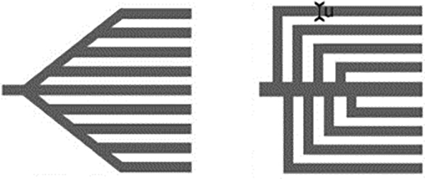
In microsystems for biotechnology, many different designs have been experimentally developed for closed systems.3,12 Figure 1 shows two designs having the shape of a tree.
Figure 1.
Tree-line capillary pump designs from Zimmermann et al.12
Here, the mechanisms at the basis of capillary pumping in open channels are investigated based on the analysis of the flow in a “capillary tree” (i.e., an ensemble of channels with bifurcations mimicking the shape of a tree). Shou et al. have theoretically studied closed cylindrical networks, however they did not include experiments).32 As Shou, we conclude that LWR law must be modified to account for the ramifications.
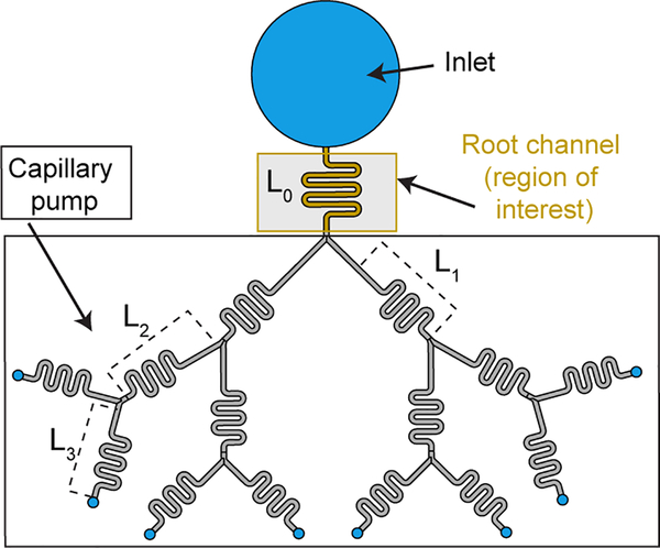
Velocity (and flow rate) decreases steadily in uniform cross section open channels. If one wants to avoid this decrease in the “root channel” i.e., the channel of interest for biological or chemical applications, a capillary pumping device should be added behind the root channel (Figure 2). We first show that a capillary tree with identical cross section provides a nearly constant flow rate in the root channel. It is assumed that the capillary tree is “symmetrical”, i.e., all branches at the same level of ramification are identical. Then, the travel distance is the same for each path, and is obtained by writing the balance between the capillary force on the advancing meniscus and the wall friction along the path. Second, we show that an improved capillary tree (with decreasing cross-sectional areas and small lengths) may even increase the flow rate in the root channel. The approach is done considering an open system, but readily applies to closed systems. The model is checked against experiments performed with nonanol flowing in open microfluidic channels (U-grooves) milled in poly(methyl methacrylate). Our approach unveils a path for designing efficient capillary pumps with marked flow rate enhancements.
Figure 2.
Schematic showing a capillary pump (in the form of a tree-like structure). Capillary pump can be placed downstream of any channel of interest. We included a small winding channel labelled root channel as an example channel of interest where biological or chemical applications could take place.
1. Materials and methods
Capillary tree channels.
The devices comprise a wide inlet port in which the liquid is fed from a pipette, and outlet ports at the extremity of the channels (see SI section 5 for the schematic of the devices). In this work, open rounded channels of different lengths, widths and depths have been used (dimensions given in Figures 6, 8, and SI. 4 and 5).
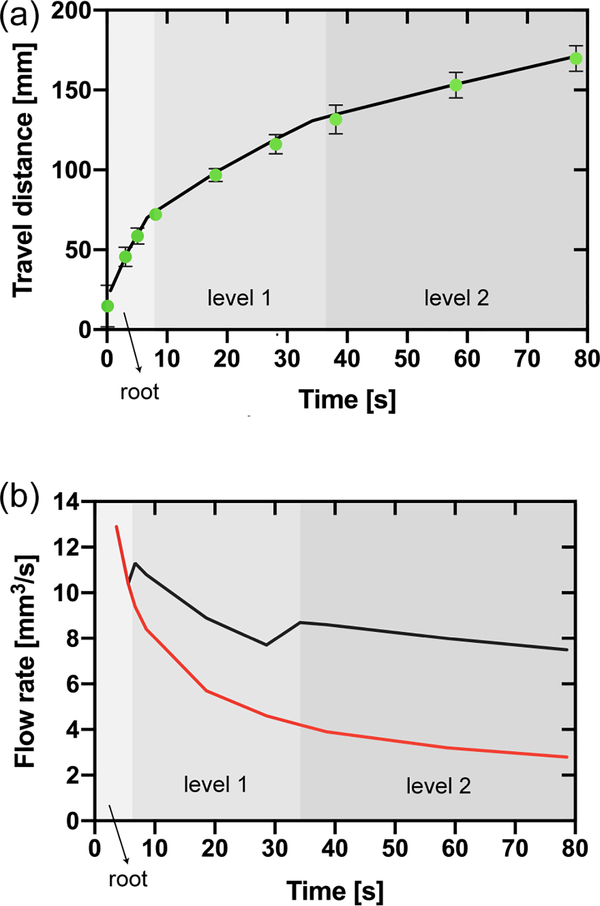
Figure 6.
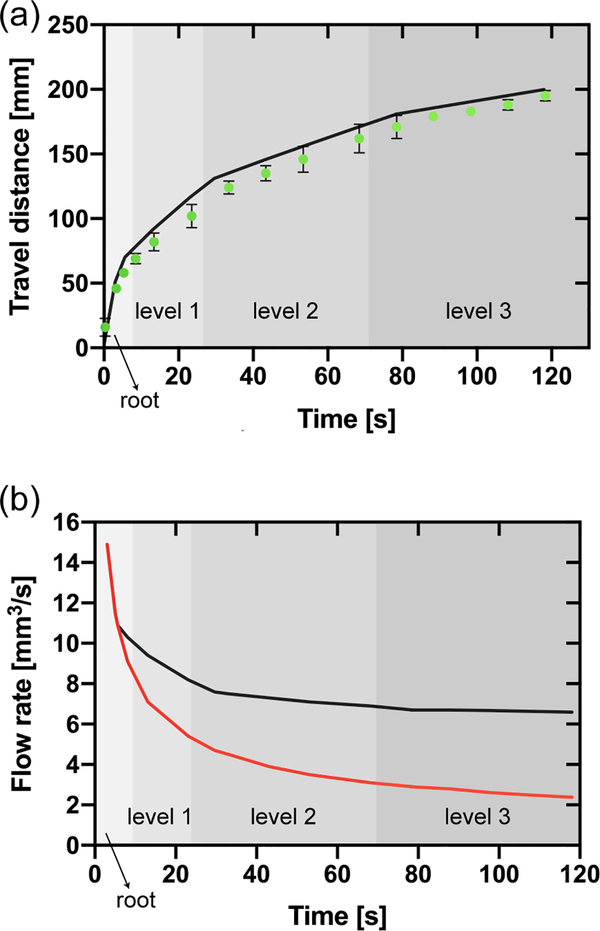
(a) Travel distances in the bifurcating capillary tree vs. time (corresponding to the design shown in Figure 5). The green dots correspond to the experimental travel distances (average of three replicates and error bars are standard deviation of the mean), and the black line to the theoretical model (equation 15). (b) Comparison between the flow rate in the root channel in the bifurcating capillary tree (black line) and in a single channel (red line) based on the theoretical model (equation18). The shading in the figure only applies to the black line and indicates the position of the fluid front within the capillary tree corresponding to the flow rate in the root channel (black line).
Figure 8.
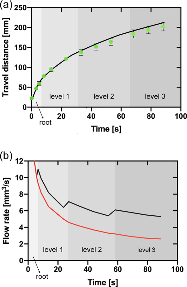
(a) Travel distances in the homothetic bifurcating capillary tree vs. time (corresponding to equation 25 and to the design shown in Figure 7). The green dots correspond to the experimental travel distances (average of three replicates and error bars are standard deviation of the mean), and the black line to the theoretical model (equation 25). (b) Comparison between the flow rate in the root channel in the homothetic bifurcating capillary tree (black line) and in a single channel (red line) based on the theoretical model (equation 18 modified for 25). The shading in the figure only applies to the black line and indicates the position of the fluid front within the capillary tree corresponding to the flow rate in the root channel (black line). Jumps in the flow rate are due to the crossing of the flow through bifurcations. These jumps are nearly instantaneous, but the time step of the calculation smears somewhat the jumps.
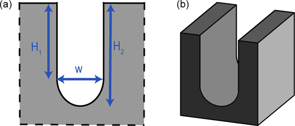
The use of winding channels is required due to the dimensions of the solid plate. Previous studies have shown that the turns do not affect the capillary flow in the absence of capillary filaments, as is the case in our study due to the U-shaped channel cross section.33 A typical channel cross section is shown in Figure 3. The cross section of the channel is a vertical groove with a rounded bottom, which avoids the formation of filaments observed in channels of rectangular cross section.
Figure 3.
(a) Detail of the cross section.
(b) Perspective view of the rounded channel.
We investigate first the flow behavior in capillary trees with the same cross section as that of Figure 3 in the whole tree. The average friction length (we will see later the use of the friction length) was estimated to be μm (calculated using COMSOL34) for the homothetic channel of 0.80 mm of width, in our preceding study.35 The friction length was defined in an early publication35 (and included again here in SI section 6) Using an approximate homothetic ratio, an estimate of the friction length in the root channel of 1.06 mm of width is 259 μm.
Secondly, we investigate the case of capillary trees with homothetically decreasing channel cross sections.
The different characteristics of the cross sections are given in the Table 1.
Table 1.
Characteristic dimensions of the channels
| Level 0 | Level 1 | Level 2 | Level 3 | |
|---|---|---|---|---|
| Width[mm] | 1.06 | 0.90 | 0.77 | 0.65 |
| Depth[mm] | 1.76 | 1.50 | 1.28 | 1.08 |
| Wetted perimeter[mm] | 4.13 | 3.51 | 3.00 | 2.53 |
| Friction length[μm] | 259 | 220 | 187 | 159 |
| Cross sectional area[mm2] | 1.75 | 1.26 | 0.92 | 0.66 |
The channels were designed using computer-aided design (CAD) software (Solidworks 2017, Waltham, MA). The design files were converted to G-code using CAM (computer aided manufacturing) software (Fusion 350) for micromilling. Channels were milled in PMMA (poly(methyl methacrylate) plates of 3.175 mm thickness (#8560K239; McMaster-Carr, Santa Fe Springs, CA) using a 2 flute ball endmill with cutter diameter of 1/32” (TR-2–0313-BN), or a 2 flute square endmill with cutter diameter of 1/16” (TR-0625-S) purchased from Performance Micro Tool, Janesville, WI. The devices were fabricated using a Datron Neo computer numerical control (CNC) mill (Datron, Germany). Roughness of the channel bottom is of the order of a few microns, one order of magnitude less than the values that would produce velocity fluctuations as observed by Lade.27
Materials.
Nonanol was used for the study as it is a low-volatility solvent (boiling point 213 °C), mitigating evaporation. The physical properties of nonanol are indicated in Table 2.36,37 Nonanol has been colored with Solvent Green 3 from Sigma-Aldrich at concentrations of 1.43 mg/mL. The volume of nonanol added to the inlet channel was ~ 1.2 mL. Additional nonanol was added, once fluid reached third branch in the bifurcation device. This is to maintain a flat meniscus in the inlet.
Table 2.
Physical properties of nonanol (in the PMMA channel) at 20°C.
| Physical properties | Value |
|---|---|
| Viscosity μ | 11.2 Pa.s |
| Surface tension γ | 28.5 mN/m |
| Young contact angle θ | 13° |
| Cassie contact angle θ* | 53° |
| Coefficient C (relation (4)) | 794 mm2/s |
Imaging.
Top-view images were recorded using a Nikon-D5300, ultra-high resolution SLR camera.
2. Theory
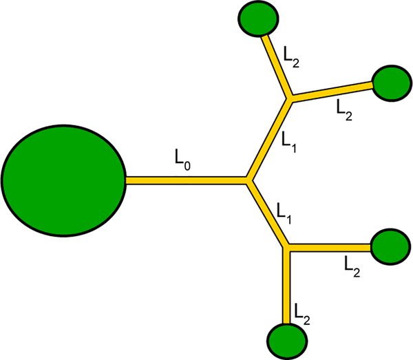
We first examine the case of a simple capillary network, which has the shape of a tree (Figure 4). In order to simplify the first algebraic developments, all the channels are assumed to have the same cross section. In such a case, the flow is “symmetrical”, i.e. the advancing menisci of the flow are theoretically located at the same place in all daughter channels of each level.
Figure 4.
Schematic of the capillary tree with the inlet port (left) and the four outlet ports.
Starting with the root channel: The travel distance z0 in the root channel is given by the balance between friction and capillary force6
| (1) |
where is the average friction, p the channel perimeter in a cross section, V0 the average velocity (which is a function of time and/or travel distance), the average friction length,6 the viscosity, the surface tension, and the generalized Cassie angle (in order to take into account the free surface of the open channel6,9 and accommodate for the potential of non-monolithic channels comprising different materials on the floor and walls; see SI section 1 for definition of generalized Cassie angle). Then we have the relation between travel distance and time
| (2) |
And finally
| (3) |
Note that the time at which the flow reaches the bifurcation at a distance L0 from entrance, is
| (4) |
where . After the first bifurcation, we must use a formulation that uses the pressures and write the pressure equilibrium along a fluidic path.35,38
| (5) |
where z1 here is the travel distance in the first ramification, S the cross-sectional area and V1 the velocity in the daughter branch (). Note that because of the assumption that the daughter branches have the same cross section as the root channel, S simplifies in (5), and there is a unique friction length and a unique Cassie angle . Integrating (5) with the condition t=t0, z1=0, and considering the mass conservation , yields
| (6) |
And the solution is simply
| (7) |
Note that the total travel distance is
| (8) |
The time t1 at which the flow reaches the end of the first branches (second bifurcations) along a distance L1, is
| (9) |
Let us proceed to the next level of ramification. The capillary pressure is still the same (since the channel cross section is uniform) but the wall friction increases.
| (10) |
Integration of (10) with the condition t = t1, z2 = 0, considering the mass conservation yields
| (11) |
and
| (12) |
Note that the total travel distance is
| (13) |
The time t2 at which the flow reaches the end of the second branches (third bifurcations) is
| (14) |
An approach using recurrence leads to the general formula for the daughter branch number n
| (15) |
and
| (16) |
In the following sections, we use the theoretical model to determine the travel distances and flow rates for three different capillary trees and compare the model with experimental results.
3. Comparison with experiments
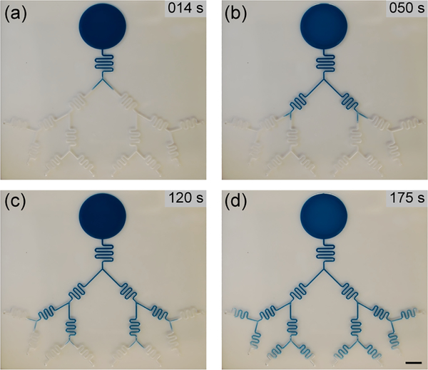
Figure 5 shows still images taken from a video of the open-channel capillary flow progressing in the capillary tree (See SI Video S1 and Figure SI.4. for the device design).
Figure 5.
Progression of the nonanol (dyed blue for visualization) in the capillary tree at (a) the first bifurcation, (b) the second bifurcation, (c) the third bifurcation and in (d) almost reaching the end of the channel. Scale bar = 1 cm.
The plot of the travel distances versus time is shown in Figure 6a. The travel distance – theoretically identical in all subchannels due to the symmetry of the tree – is calculated from equation (15) using Excel software. Elapsed time is incremented stepwise starting at time 0 seconds where the flow enters the root channel. First, using equation (3) for the root channel, the time t0 when the flow exits the root channel is determined. Then, using equation (15) for n = 1, the time t1 where the flow exits the first daughter branches, is determined, and so on, until the last ramifications. Derivation of the travel distance versus time then yields the velocities in the capillary tree. Note that after the first bifurcation, the velocities are nearly constant in the device. The analytical form of the velocity in the capillary tree is given by derivation of (15)
| (17) |
where An is a constant depending on the daughter channels lengths and ramification level.
At each bifurcation, there is a negative jump of velocity. It is similar to what is observed with a widening of a unique channel.39–41 On the other hand, the total flow rate is nearly constant after the second level of bifurcations, as shown in Figure 6b. Using (17), flow rates are given by
| (18) |
The velocity of the tip of the flow is the time derivative of the travel distance given by equation (15) where Vn = dzn/dt. Denoting An = 2nL0 + ⋯ + 2 n−1Ln-1, we obtain equation (17) for the velocity at the tip of the flow. The flow rate at the tip of the flow is obtained by multiplying the velocity by the cross-sectional area. Finally, the total flow rate (in the root channel) is obtained by adding the contribution of all the flow tips, resulting in equation (18). The term 2n−1 accounts for the summation for the bifurcating trees. For trifurcating trees, this would be 3n-1.
In the following section, we investigate the effect of a progressive decrease of the cross-sectional areas of the channels.
4. Decreasing cross-sectional areas and capillary pumping.
Let us now consider a capillary tree where the cross sections decrease by a homothetic ratio (i.e., channel width and height decrease by the same factor) from one level to the next.
4.1. Bifurcating capillary trees.
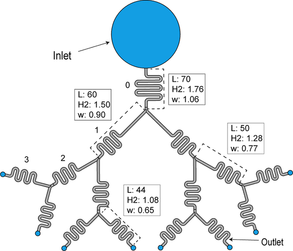
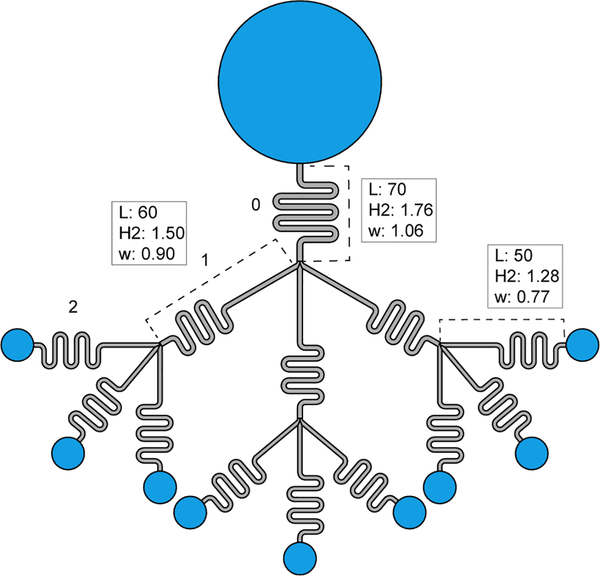
In a first step, we investigate capillary trees where channels divisions are bifurcations (two daughter channels for one mother channel), as shown in Figure 7. In such a case the cross-sectional perimeters are
| (19) |
and the cross-sectional areas are
| (20) |
Figure 7.
View of the capillary tree with homothetically decreasing cross sections. The homothetic ratio is α = 0.85. Units in mm, and L is length of the respective channel part in the device (see SI Figure SI.4 for additional dimensions).
Moreover, the friction lengths are homothetic because they are proportional to the hydraulic diameter of the channel
| (21) |
Hence the ratio is constant, equal to . Moreover, the Cassie angles are everywhere the same, i.e., . Generalizing (10), considering the change of the cross section at each ramification level, we obtain
| (22) |
The mass conservation equation yields
| (23) |
We then can integrate (22) under the form of a quadratic polynomial in zn
| (24) |
And the solution is
| (25) |
It is easily verified that, for α = 1, equation (25) reduces to equation (15). Figure 8 shows the results for the device shown in Figure 7 (α = 0.85).
4.2. Trifurcating capillary trees
In this section, the flow behavior in a trifurcating capillary tree is investigated. Figure 9 shows the device used for performing the experiments. Here, the capillary flow first divides in the two “exterior” channels because of the immediate presence of the walls, but the flow equilibrates somewhat later (sometimes a small delay in the middle channel can be observed). In the case of trifurcating devices, the approach is like that of the preceding section. However, the mass conservation equation (23) becomes
| (26) |
Figure 9.
Trifurcating capillary tree with homothetically decreasing cross sections. The homothetic ratio is α = 0.85. Units in mm, and L is length of the respective channel part in the device (see SI Figure SI.5 for additional dimensions).
Then, in a similar integration as for equation (22), we obtain the solution
| (27) |
Using the geometrical data of Figure 9, we obtain the travel distances vs. time shown in Figure 10.
Figure 10.
(a) Travel distances in the homothetic trifurcating capillary tree vs. time (corresponding to equation 27 and to the design shown in Figure 9). The green dots correspond to the experimental travel distances (average of three replicates and error bars are standard deviation of the mean), and the black line to the theoretical model (equation 27). (b) Comparison between the flow rate in the root channel in the homothetic trifurcating capillary tree (black line) and in a single channel (red line) based on the theoretical model (equation 18 modified for 27). The shading in the figure only applies to the black line and indicates the position of the fluid front within the capillary tree corresponding to the flow rate in the root channel (black line). Jumps in the flow rate are due to the crossing of the flow through bifurcations. These jumps are nearly instantaneous, but the time step of the calculation smears somewhat the jumps.
5. Discussion
In the preceding sections, we have shown that the theoretical model reproduces well experimental travel distances in capillary trees. Moreover, it has been shown that the travel distances in the different branches of the tree are not of the form , but of the form . A similar relation was also obtained in the case of networks.35
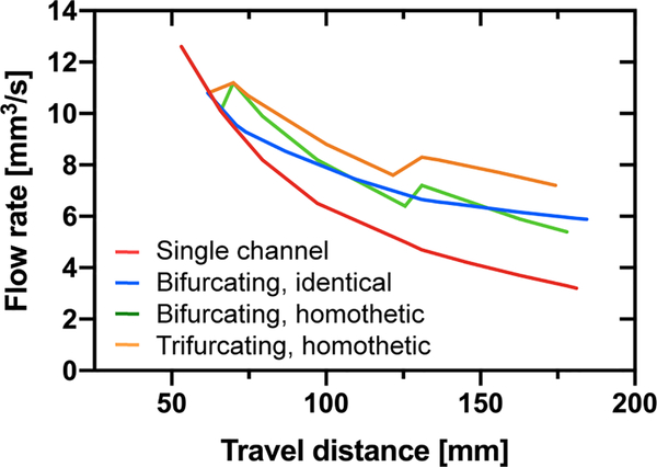
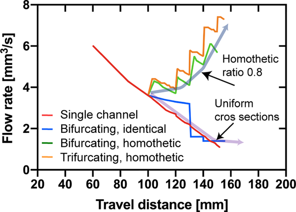
Let us now consider the flow rates. A comparison between all the cases studied here is shown in Figure 11. As expected, the trifurcating capillary tree with decreasing cross sections produces the highest flow rates.
Figure 11.
Comparison of the flow rates in the capillary trees: Flow rates vs. travel distance. The largest flow rates are associated to the trifurcating devices with decreasing cross-sections. Flow rates are calculated with LW equation (single channel), equation 18 (bifurcating, identical), equation 25 (bifurcating, homothetic), and equation 27 (trifurcating, homothetic).
Let us now consider the question: what morphology of the capillary tree produces the highest flow rate? In other words, what morphology corresponds to the best pumping efficiency? In the following, we do not consider the feasibility of the fabrication, but only the theoretical optimum.
The parameters of the geometry of the capillary tree are (1) the number of divisions at each ramification, (2) the lengths of the flow channels, and (3) the homothetic ratio for the cross sections of the flow channels between each ramification. Note that relations (25) and (27) can be generalized to a higher number of divisions at each ramification. In such case, the coefficients 2 in (25) and 3 in (27) are replaced by the number of divisions. The number of parameters is large, making it difficult to detail the influence of each parameters. In the simplified case of daughter channels of equal length, a mathematical approach can be done and is presented in SI section 2–4. The approach concludes that short channels lengths, large number of sub-channels at a division (node) and homothetic ratios of the order of 0.7 – 0.8 produce the highest flow rate. In the following, we use our model to analyze more concretely the influence of the parameters.
In order to answer these questions, let us consider a two capillary trees with 4 ramification levels and a homothetic ratio α = 0.8 between each level. These capillary trees have flow segments of much shorter lengths than that considered before, of the order of 10 to 20 mm only. The different lengths and cross sections are listed in Table 3.
Table 3.
Geometrical characteristics of the tree
| Length Case #1 [mm] | Length Case #2 [mm] | Cross section [mm2] | Friction length [μm] | |
|---|---|---|---|---|
| Root | 100 | 100 | 1 | 200 |
| Level #1 | 50 | 20 | 0.8 | 160 |
| Level #2 | 20 | 10 | 0.64 | 128 |
| Level #3 | 20 | 10 | 0.51 | 102.4 |
| Level #4 | 20 | 10 | 0.41 | 81.9 |
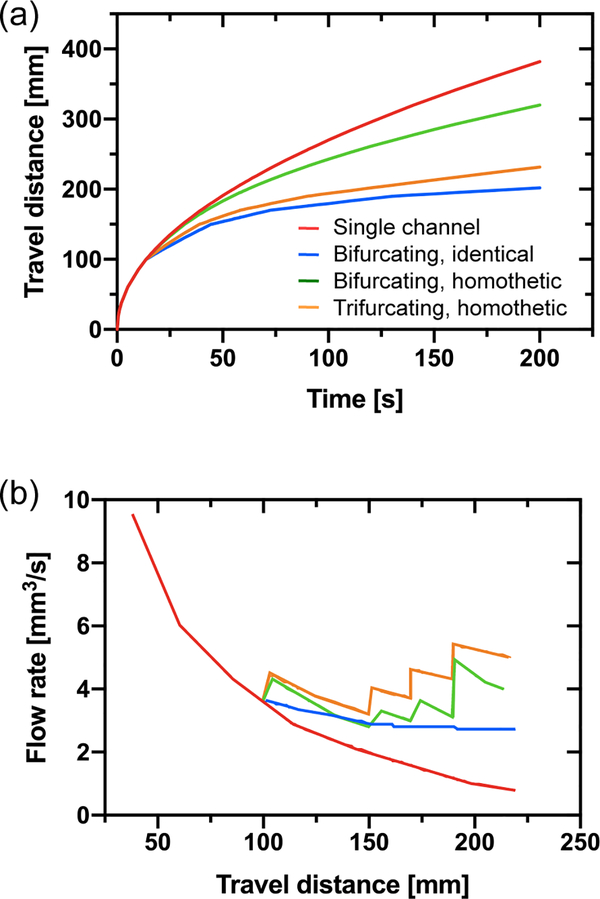
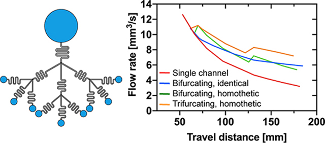
The calculated travel distances and flow rates are shown in Figure 12 and 13 for cases #1 and #2 respectively.
Figure 12.
Case #1. The case of the single channel (red line) is compared to that of the bifurcating and trifurcating capillary trees. “Identical” refers to a capillary tree of uniform cross sections, while “homothetic” refers to a capillary tree with homothetically decreasing cross sections. (a) Travel distance in the successive channels (with the homothetic ratio 0.8) as a function of time calculated using equations (25) and (27). (b) Flow rate vs. travel distance.
Figure 13.
Case #2. The case of the single channel (red line) is compared to that of the bifurcating and trifurcating capillary trees. The flow rate increases when the channel cross sections are homothetically reduced (green and orange line), resulting in a pumping effect.
Clearly, the shorter channels lengths associated to the progressive reduction of the cross-sectional areas have the effect to bring the travel distances closer with that of the generalized/modified LWR (Lucas-Washburn-Rideal) law for the case of the single channel. Homothetically decreasing the channel cross-sectional areas increases the total flow rate, as shown in Figure 13. Even if the flow velocity suddenly decreases at each bifurcation, the total flow rate increases because of the contribution of the additional daughter branches. Hence, an important increase of flow rates is obtained by the reduction of the channel lengths and of the cross-sections at each bifurcation, when the length of the branches is sufficiently small.
6. Conclusion
The present analysis demonstrates the possibility of obtaining nearly constant flow rates by using a capillary tree of same cross-sectional areas. Once the flow has invaded the root channel and is divided in the daughter branches, the fluid velocity is nearly constant in the wetted channels. This solves a significant problem in capillary-driven microfluidics: decrease in fluid flow rate along the length of the channel that is observed in simple non-bifurcating channels.
Moreover, it is shown that decreasing the channel lengths and slightly decreasing the areas of the channel cross-section at each level of the tree has the effect to stepwise increase the flow rate each time that the tip of the flow passes a bifurcation. A more pronounced effect is obtained with trifurcations. Hence, this work provides insight into the physics of capillary pumping: in order to obtain efficient pumping, the capillary network should be constituted of channels of small lengths and of (slightly) decreasing cross sections. We expect this insight to be useful when designing capillary-driven microfluidic systems for applications requiring efficient flow of a volume of fluid that would be challenging to deliver with non-bifurcating channels. Potential applications include sample preparation, cell culture, assay workflows (reagent delivery, washing, etc.), and chemical reactions.
A limitation to flow rate amplification stems from geometrical and fabrication considerations. For example, the reduction of the dimensions of the cross section with a homothetic factor of 0.8 results in channel widths of 1000, 800, 640, 512, 410, 328 and 262 μm for a six-level capillary tree. One reaches quickly the limits of milling channels in a plastic plate, first because of the smaller dimensions of the endmill, and second, because of the steric arrangement of the tree in the substrate (the overall device footprint).
However, methods other than milling are commonly used in microfluidic device fabrication, and our work here provides a general framework for evaluating flow rate gain in capillary trees with channels of any dimension.
Finally, we remark that the most efficient pumping—obtained by using very short channels with many divisions—has a morphology resembling that of fibrous media. In order to have a pumping efficiency similar to that of a fibrous media, the characteristic length of the capillary tree should be of the same order of the characteristic dimension of the fibrous media. We assume this is the reason why it is found impossible to extract by capillary means liquid from a fibrous media towards open channels provided that the open cannel has a radius larger than the effective capillary radius in the pore space.
Supplementary Material
Acknowledgements
This work was funded by NIH grant R35GM128648 (JJL and ABT) and the University of Washington. We also acknowledge the Biochemical Diagnostics Foundry for Translational Research supported by the MJ Murdock Trust.
Footnotes
Conflicts of interests
The authors declare the following competing financial interest(s): The authors acknowledge the following potential conflicts of interest in companies pursuing open microfluidic technologies: E.B: Tasso, Inc., Salus Discovery, LLC, and Stacks to the Future, LLC; A.B.T: Stacks to the Future, LLC.
References
- (1).Gervais L; Hitzbleck M; Delamarche E Capillary-Driven Multiparametric Microfluidic Chips for One-Step Immunoassays. Biosens. Bioelectron. 2011, 27 (1), 64–70. 10.1016/J.BIOS.2011.06.016. [DOI] [PubMed] [Google Scholar]
- (2).Safavieh R; Juncker D Capillarics: Pre-Programmed, Self-Powered Microfluidic Circuits Built from Capillary Elements. Lab Chip 2013, 13, 4180–4189. 10.1039/c3lc50691f. [DOI] [PubMed] [Google Scholar]
- (3).Olanrewaju A; Beaugrand M; Yafia M; Juncker D Capillary Microfluidics in Microchannels: From Microfluidic Networks to Capillaric Circuits. Lab on a Chip. Royal Society of Chemistry August 7, 2018, pp 2323–2347. 10.1039/c8lc00458g. [DOI] [PubMed] [Google Scholar]
- (4).Juncker D; Schmid H; Ute D; Heiko W; Marc W; Bruno M; Nico de R.; Emmanuel D Autonomous Microfluidic Capillary System. Anal. Chem. 2002, 74, 6139–6144. 10.1021/AC0261449. [DOI] [PubMed] [Google Scholar]
- (5).Temiz Y; Delamarche E Sub-Nanoliter, Real-Time Flow Monitoring in Microfluidic Chips Using a Portable Device and Smartphone. Sci. Rep. 2018, 8 (1). 10.1038/s41598-018-28983-w. [DOI] [PMC free article] [PubMed] [Google Scholar]
- (6).Berthier J; Brakke KA; Berthier E Open Microfluidics; Wiley, 2016. [Google Scholar]
- (7).Berthier J; Theberge AB; Berthier E Open-Channel Microfluidics, IOP Collection; Morgan & Claypool, 2019. [Google Scholar]
- (8).Oliveira NM; Vilabril S; Oliveira MB; Reis RL; Mano JF Recent Advances on Open Fluidic Systems for Biomedical Applications: A Review. Materials Science and Engineering C. Elsevier Ltd April 1, 2019, pp 851–863. 10.1016/j.msec.2018.12.040. [DOI] [PubMed] [Google Scholar]
- (9).Berthier E; Dostie AM; Lee UN; Berthier J; Theberge AB Open Microfluidic Capillary Systems. Analytical Chemistry. American Chemical Society July 1, 2019, pp 8739–8750. 10.1021/acs.analchem.9b01429. [DOI] [PMC free article] [PubMed] [Google Scholar]
- (10).Yu J; Berthier E; Craig A; de Groot TE; Sparks S; Ingram PN; Jarrard DF; Huang W; Beebe DJ; Theberge AB Reconfigurable Open Microfluidics for Studying the Spatiotemporal Dynamics of Paracrine Signalling. Nat. Biomed. Eng. 2019, 3 (10), 830–841. 10.1038/s41551-019-0421-4. [DOI] [PMC free article] [PubMed] [Google Scholar]
- (11).Chen Y; Melvin LS; Rodriguez S; Bell D; Weislogel MM Capillary Driven Flow in Micro Scale Surface Structures. Microelectron. Eng. 2009, 86 (4–6), 1317–1320. 10.1016/j.mee.2009.02.016. [DOI] [Google Scholar]
- (12).Zimmermann M; Schmid H; Hunziker P; Delamarche E Capillary Pumps for Autonomous Capillary Systems. Lab Chip 2007, 7 (1), 119–125. 10.1039/b609813d. [DOI] [PubMed] [Google Scholar]
- (13).Lucas R Ueber Das Zeitgesetz Des Kapillaren Aufstiegs von Flüssigkeiten. Kolloid-Zeitschrift 1918, 23, 15–22. 10.1007/BF01461107. [DOI] [Google Scholar]
- (14).Washburn EW The Dynamics of Capillary Flow. Phys. Rev. 1921, 17 (3), 273–283. 10.1103/PhysRev.17.273. [DOI] [Google Scholar]
- (15).Rideal EK On the Flow of Liquids under Capillary Pressure. Philos. Mag. Ser. 6 1922, 44, 1152–1159. 10.1080/14786441008634082. [DOI] [Google Scholar]
- (16).Bosanquet CH On the Flow of Liquids into Capillary Tubes. Philos. Mag. Ser. 6 1923, 45, 525–531. 10.1080/14786442308634144. [DOI] [Google Scholar]
- (17).Rye RR; Yost FG; Mann JA Wetting Kinetics in Surface Capillary Grooves. Langmuir 1996, 12, 4625–4627. 10.1021/la9605201. [DOI] [Google Scholar]
- (18).Yost FG; Rye RR; Mann JA Solder Wetting Kinetics in Narrow V-Grooves. Acta Mater. 1997, 45, 5337–5345. 10.1016/S1359-6454(97)00205-X. [DOI] [Google Scholar]
- (19).Romero LA; Yost FG Flow in an Open Channel Capillary. J. Fluid Mech. 1996, 322, 109–129. 10.1017/S0022112096002728. [DOI] [Google Scholar]
- (20).Kitron-Belinkov M; Marmur A; Trabold T; Dadheech GV Groovy Drops: Effect of Groove Curvature on Spontaneous Capillary Flow. Langmuir 2007, 23, 8406–8410. 10.1021/LA700473M. [DOI] [PubMed] [Google Scholar]
- (21).Conrath M; Canfield PJ; Bronowicki PM; Dreyer ME; Weislogel MM; Grah A Capillary Channel Flow Experiments Aboard the International Space Station. Phys. Rev. E 2013, 88, 063009. 10.1103/PhysRevE.88.063009. [DOI] [PubMed] [Google Scholar]
- (22).Weislogel MM; Chen Y; Bolleddula D A Better Nondimensionalization Scheme for Slender Laminar Flows: The Laplacian Operator Scaling Method. Phys. Fluids 2008, 20, 93602. 10.1063/1.2973900. [DOI] [Google Scholar]
- (23).Yang D; Krasowska M; Priest C; Popescu MN; Ralston J Dynamics of Capillary-Driven Flow in Open Microchannels. J. Phys. Chem. C 2011, 115, 18761–18769. 10.1021/jp2065826. [DOI] [PubMed] [Google Scholar]
- (24).Ouali FF; McHale G; Javed H; Trabi C; Shirtcliffe NJ; Newton MI Wetting Considerations in Capillary Rise and Imbibition in Closed Square Tubes and Open Rectangular Cross-Section Channels. Microfluid. Nanofluidics 2013, 15 (3), 309–326. 10.1007/s10404-013-1145-5. [DOI] [Google Scholar]
- (25).Baret J-C; Decré MMJ; Herminghaus S; Seemann R Transport Dynamics in Open Microfluidic Grooves. Langmuir 2007, 23, 5200–5204. 10.1021/LA063584C. [DOI] [PubMed] [Google Scholar]
- (26).Berthier J; Brakke KA; Furlani EP; Karampelas IH; Poher V; Gosselin D; Cubizolles M; Pouteau P Whole Blood Spontaneous Capillary Flow in Narrow V-Groove Microchannels. Sensors Actuators, B Chem. 2015, 206, 258–267. 10.1016/j.snb.2014.09.040. [DOI] [Google Scholar]
- (27).Lade RK; Hippchen EJ; Macosko CW; Francis LF Dynamics of Capillary-Driven Flow in 3D Printed Open Microchannels. Langmuir 2017, 33 (12), 2949–2964. 10.1021/acs.langmuir.6b04506. [DOI] [PubMed] [Google Scholar]
- (28).Berthier J; Brakke KA; Berthier E A General Condition for Spontaneous Capillary Flow in Uniform Cross-Section Microchannels. Microfluid. Nanofluidics 2014, 16, 779–785. 10.1007/s10404-013-1270-1. [DOI] [Google Scholar]
- (29).Elizalde E; Urteaga R; Berli CL A. Rational Design of Capillary-Driven Flows for Paper-Based Microfluidics. Lab Chip 2015, 15 (10), 2173–2180. 10.1039/C4LC01487A. [DOI] [PubMed] [Google Scholar]
- (30).Tsai YF; Shieh CJ; Yang H Capillary Force Pumping Fluid for Glucose Oxidase Enzymatic Fuel Cells . Microsyst. Technol. 2017, 23 (9), 3927–3935. 10.1007/s00542-015-2728-8. [DOI] [Google Scholar]
- (31).Liu H; Zhang X; Hong Z; Pu Z; Yao Q; Shi J; Yang G; Mi B; Yang B; Liu X; Jiang H; Hu X A Bioinspired Capillary-Driven Pump for Solar Vapor Generation. Nano Energy 2017, 42, 115–121. 10.1016/j.nanoen.2017.10.039. [DOI] [Google Scholar]
- (32).Shou D; Ye L; Fan J Treelike Networks Accelerating Capillary Flow. Phys. Rev. E - Stat. Nonlinear, Soft Matter Phys. 2014, 89 (5), 053007. 10.1103/PhysRevE.89.053007. [DOI] [PubMed] [Google Scholar]
- (33).Berthier J; Brakke KA; Gosselin D; Navarro F; Belgacem N; Chaussy D Spontaneous Capillary Flow in Curved, Open Microchannels. Microfluid. Nanofluidics 2016, 20 (7), 1–9. 10.1007/s10404-016-1766-6. [DOI] [Google Scholar]
- (34).COMSOL Multiphysics® Modeling Software https://www.comsol.com/ (accessed Aug 28, 2018).
- (35).Lee JJ; Berthier J; Theberge AB; Berthier E Capillary Flow in Open Microgrooves: Bifurcations and Networks. Langmuir 2019, 35 (32), 10667–10675. 10.1021/acs.langmuir.9b01456. [DOI] [PubMed] [Google Scholar]
- (36).Mohammad AA; Alkhaldi KHAE; AlTuwaim MS; Al-Jimaz AS Effect of Temperature and Chain Length on the Viscosity and Surface Tension of Binary Systems of N,N-Dimethylformamide with 1-Octanol, 1-Nonanol and 1-Decanol. J. Chem. Thermodyn. 2014, 74, 7–15. 10.1016/J.JCT.2014.03.022. [DOI] [Google Scholar]
- (37).Kim S; Thiessen PA; Bolton EE; Chen J; Fu G; Gindulyte A; Han L; He J; He S; Shoemaker BA; Wang J; Yu B; Zhang J; Bryant SH PubChem Substance and Compound Databases. Nucleic Acids Res. 2016, 44. 10.1093/nar/gkv951. [DOI] [PMC free article] [PubMed] [Google Scholar]
- (38).Mehrabian H; Gao P; Feng JJ Wicking Flow through Microchannels. Phys. Fluids 2011, 23 (12), 122108. 10.1063/1.3671739. [DOI] [Google Scholar]
- (39).Erickson D; Li D; Park CB Numerical Simulations of Capillary-Driven Flows in Nonuniform Cross-Sectional Capillaries. J. Colloid Interface Sci. 2002, 250 (2), 422–430. 10.1006/jcis.2002.8361. [DOI] [PubMed] [Google Scholar]
- (40).Berthier J; Gosselin D; Pham A; Delapierre G; Belgacem N; Chaussy D Capillary Flow Resistors: Local and Global Resistors. Langmuir 2016, 32 (3), 915–921. 10.1021/acs.langmuir.5b02090. [DOI] [PubMed] [Google Scholar]
- (41).Berthier J; Gosselin D; Pham A; Boizot F; Delapierre G; Belgacem N; Chaussy D Spontaneous Capillary Flows in Piecewise Varying Cross Section Microchannels. Sensors Actuators, B Chem. 2016, 223, 868–877. 10.1016/j.snb.2015.10.023. [DOI] [Google Scholar]
Associated Data
This section collects any data citations, data availability statements, or supplementary materials included in this article.


