

A star-shaped polymer enables inverted perovskite solar cells with efficiency over 22% and a very high fill factor of 0.862.
Abstract
Stabilizing high-efficiency perovskite solar cells (PSCs) at operating conditions remains an unresolved issue hampering its large-scale commercial deployment. Here, we report a star-shaped polymer to improve charge transport and inhibit ion migration at the perovskite interface. The incorporation of multiple chemical anchor sites in the star-shaped polymer branches strongly controls the crystallization of perovskite film with lower trap density and higher carrier mobility and thus inhibits the nonradiative recombination and reduces the charge-transport loss. Consequently, the modified inverted PSCs show an optimal power conversion efficiency of 22.1% and a very high fill factor (FF) of 0.862, corresponding to 95.4% of the Shockley-Queisser limited FF (0.904) of PSCs with a 1.59-eV bandgap. The modified devices exhibit excellent long-term operational and thermal stability at the maximum power point for 1000 hours at 45°C under continuous one-sun illumination without any significant loss of efficiency.
INTRODUCTION
Hybrid organic-inorganic halide perovskites are attractive photoelectric materials exhibiting the advantages of low cost (1) and ease in manufacturing (2) while exhibiting strong panchromatic sunlight absorption (3), long carrier diffusion lengths (4), and adjustable direct bandgaps (5). The power conversion efficiencies (PCEs) of perovskite solar cells (PSCs) achieved within only a few years have reached 25.5% (6–9) using the regular (n-i-p) structure. Unfortunately, the PCE of inverted (p-i-n) PSCs lags significantly behind that of regular structured devices. Although the open-circuit voltage (Voc), short-circuit current (Jsc), and fill factor (FF) are highly correlated and synergistically affect the PCE, most researchers have principally dedicated their efforts to optimizing Voc and Jsc rather than attempting to comprehend and optimize the FF value (10). In most cases, the FF values of PSCs usually exhibit low values between 0.7 and 0.8, and even those devices with certified 22.7% (11) and 23.3% (12), PCEs show an FF value lower than 0.8. Recently, a higher FF value of 0.848 has been achieved, which likely played a determining role in reaching a 25.2% PCE (7).
For FF optimization, low series resistances (Rs) and large shunt resistances (Rsh) are usually required (13). The Rs in a PSC can be determined by ohmic elements, for example, the conductive base, electron and hole transport layer (ETL and HTL, respectively), and metal back contact (14). Increasing the conductivity and mobility of the ETL and HTL will help to improve the FF in PSCs. To improve the Rsh value, the leakage current caused by carrier recombination in the bulk and at interfaces should be minimized (15). Among various types of recombination, defect-induced recombination plays a major role in the reduction of the FF and Voc (16). Until present, many passivation methods have been proposed to reduce the defect density, significantly boosting Rsh and reducing defect-induced recombination (17–19). Additives based on the Lewis acid-base theory (20, 21) including solvents (22), ionic liquids (23, 24), small molecules (25–27), and polymers (28, 29) are used to modify perovskite films with various functional groups. When used as additives, the high volatility and high diffusion coefficient of small molecules may make it difficult to maintain the long-term stability of PSCs under extreme conditions (30–33). For these reasons, several attempts have instead been made to use polymers as additives (28, 29, 34). These polymers, however, generally have a one-dimensional (1D) linear structure and can only show a single passivation effect when they modify the surface of perovskite films. Few researchers directly passivate perovskite films through 3D polymers that have multiple branches and multiple functional groups on each branch.
Here, we have designed a 3D star-shaped polyhedral oligomeric silsesquioxane-poly(trifluoroethyl methacrylate)-b-poly(methyl methacrylate) (PPP) polymer as a novel modulator to regulate perovskite film crystallization (Fig. 1A). The polyhedral oligomeric silsesquioxane serving as a core in the star-shaped PPP material is surrounded by eight branches, including poly(trifluoroethyl methacrylate) and poly(methyl methacrylate) molecular chains. The core is a type of organic-inorganic intramolecular hybrid material with a highly symmetrical rigid Si─O─Si cubic cage skeleton, which can offer the PPP material 3D structure stability (35). Poly(trifluoroethyl methacrylate) is a type of special fluoropolymer that exhibits outstanding hydrophobic and anti-adhesion properties (36). On the PPP polymer branches, there are multiple chemical anchor sites including carbonyl (C═O) and ─CF3, which act as 3D skeleton templates to passivate defects at the grain boundaries (GBs) and interfacial surfaces, inhibit nonradiative recombination and charge-transport loss, and improve stabilities under moisture, thermal, and illumination stress. As a result, the PPP-modified inverted devices obtain an optimal 22.1% efficiency and an astoundingly high FF value of 0.862. The nonencapsulated modified device exhibits a significantly enhanced environmental stability with retaining of more than 93% of the initial efficiency after 6000 hours of exposure to ambient environment atmosphere [40% relative humidity (RH), 25°C]. The encapsulated modified device exhibits excellent operational stability with almost no change in efficiency after 1000 hours of maximum power point tracking under one-sun illumination at 45°C, as well as very good thermal stability with 91% of the initial efficiency retained under continuous one-sun illumination at 75°C for 1000 hours.
Fig. 1. Interactions between the PPP polymer and perovskite.
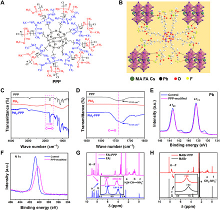
(A) Structural formula of the PPP polymer. (B) Schematic diagram of the interaction between the PPP polymer (partial 3D structure) and perovskite, including chelation between C═O and Pb and hydrogen bonding between ─CF3 and FA+ and MA+. (C) FTIR spectra of the PPP polymer, PbI2, and PPP-PbI2. (D) Fingerprint region of C═O. (E and F) XPS spectra of Pb 4f and N 1s in control and PPP-modified perovskite films. a.u., arbitrary units. (G) 1H-NMR spectra of FAI and FAI-PPP mixture. (H) 1H-NMR spectra of MABr and MABr-PPP mixture.
RESULTS
Structural and morphology characterizations
The Fourier transform infrared (FTIR) spectrum (fig. S1), 1H nuclear magnetic resonance (1H-NMR) spectrum (fig. S2), and gel permeation chromatography (GPC) (fig. S3) results confirmed the structure of the as-prepared PPP polymer. The PPP polymers used as a novel additive have been introduced into the perovskite film via a chlorobenzene antisolvent. The interaction between the PPP polymer and CsMAFA (MA, methylamine cation; FA, formamidinium cation)–based perovskite is shown in Fig. 1B, which has been investigated by combining FTIR, x-ray photoelectron spectroscopy (XPS), and 1H-NMR. First, the C═O bond of the PPP polymer chelation with noncoordinating Pb2+ is observed. As shown in Fig. 1 (C and D), the stretching vibration of the C═O bond of the PPP polymer appears at 1741 cm−1 and shifts to 1731 cm−1 when it interacts with PbI2. The shift in the C═O stretching vibration frequency of the PPP polymer to a lower wave number arises from the electron delocalization from C═O when an intermediate PPP-PbI2 adduct is formed, which demonstrates a strong interaction between PbI2 and C═O in the PPP polymer. From the XPS spectra of the PPP-modified perovskite film (fig. S4), we detect C, O, F, and Si on the top surface, and the XPS spectra of Cs 3d, Br 3d, I 3d, and Pb 4f shift after the incorporation of the PPP polymer. This phenomenon indicates that there is an interaction between the PPP polymer and perovskite. From the Pb 4f XPS spectra (Fig. 1E), there are two main peaks at 138.4 and 143.3 eV, corresponding to Pb 4f7/2 and Pb 4f5/2, respectively. In addition, the two small peaks at 136.7 and 141.6 eV are ascribed to the existence of metallic Pb in the control film. The metallic Pb peaks disappear for the PPP-modified perovskite film, showing that the PPP polymer can prevent the formation of metallic Pb.
In addition, the strong hydrogen bonding between the ─CF3 group of the PPP polymer and FA+ and MA+ in the perovskite film has been investigated. After the CsMAFA perovskite was modified by the PPP polymer, the XPS spectra of the N 1s orbital peak obtained for the CsMAFA perovskite film show a significant deviation (Fig. 1F). Furthermore, the N─H stretching vibration in the FTIR spectra of FAI and MABr perovskites shifts to lower wave number, which indicates the interaction between the N─H of the perovskite and ─CF3 functional group in the PPP polymer (fig. S5) (37). The 1H-NMR spectra are further used to demonstrate the existence of hydrogen bonds. The electronegativity of the fluorine atom is stronger than that of oxygen in the PPP polymer, so it is easy to associate with H atoms to form F···H hydrogen bonds. Once the perovskite film is modified with the PPP polymer, N─H···F hydrogen bonds are readily formed with N─H in FA+ and MA+ (38). We compare the 1H-NMR spectra of FAI and FAI-PPP–based dimethyl sulfoxide-d6 (CD3SOCD3) and chloroform-d3 (CDCl3) mixed solvent (Fig. 1G). After adding the PPP polymer, the chemical shift (δ) values of the H atoms in the NH2 and ═NH2+ show a clear shift. Furthermore, we also compare the 1H-NMR spectra of MABr and MABr-PPP solutions. Figure 1H shows that the δ value of H in NH3+ moves to the lower field direction by approximately 0.06 parts per million (ppm; from 7.63 to 7.69 ppm) after the introduction of the PPP polymer. These findings signify that the F atoms in the PPP polymer have formed a hydrogen bond with the H atoms in the NH2 and ═NH2+ of the FAI perovskite and NH3+ of the MABr perovskite.
We now explore the effects of the PPP polymer on the morphology and quality of perovskite films. The top-view scanning electron microscopy (SEM) and cross-sectional SEM images of the control and PPP-modified films are presented in Fig. 2 (A to D). Compared to the control, the PPP-modified perovskite shows a densely packed film with a larger grain size. Figure S6 shows the corresponding grain size distribution. The average grain size of the control film is approximately 260 nm, while that of the PPP-modified perovskite film is approximately 350 nm. Moreover, the cross-sectional SEM image of the control shows an irregular vertical arrangement and obvious GBs, while the PPP-modified perovskite crystals are well arranged along the vertical direction and GBs are not readily observed. These results demonstrate that the PPP polymer promotes perovskite crystallization to obtain a high-quality film. Transmission electron microscopy (TEM) is used to further study the PPP-modified perovskite film. As shown in Fig. 2 (E and F), the perovskite material is coated with a very thin amorphous phase of PPP molecules, but a good crystal structure is attested by the exposed region. The interplanar spacing of the perovskite material is confirmed to be 0.63 nm, which corresponds to the (100) plane of the CsMAFA crystal tetragonal phase (Fig. 2F). The 3D structure of the PPP polymer can bridge grains and constitute 3D skeleton templates to immobilize perovskite grains. The x-ray diffraction (XRD) patterns illustrate that the PPP molecules are not incorporated into the perovskite crystal lattice. The full width at half maximum of the (100) peak of the PPP-modified perovskite film is smaller than that of the control (fig. S7). Compared to the control, the PPP-modified film shows stronger intensities of the CsMAFA crystal but a weaker intensity of the PbI2 peaks in the XRD pattern, suggesting a larger grain size and higher crystallinity (Fig. 2G). In the PPP-modified perovskite films, enhanced absorption is also observed, which is attributed to increased crystallinity (fig. S8). Because the 3D PPP polymer branches have multiple chemical anchor sites including C═O and ─CF3, the strong interaction of the C═O bond of the PPP polymer with PbI2 and the hydrogen bonding interaction between the PPP polymer and FA+ and MA+ reduce the content of unreacted PbI2, regulating the morphology and thereby improving the quality of the perovskite film. We also combined scanning TEM imaging, energy-dispersive x-ray mapping (fig. S9), and time-of-flight secondary ion mass spectroscopy (ToF-SIMS) depth profile (fig. S10) to prove that PPP polymers are distributed in the bulk of the perovskite film.
Fig. 2. Morphology and structural properties of perovskite films.
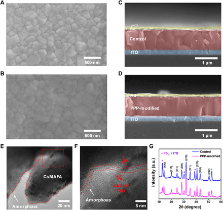
(A and B) Top-view SEM images of the control and PPP-modified perovskite films. (C and D) Cross-sectional SEM images of the control and PPP-modified perovskite films. (E) High-resolution TEM image of PPP-modified perovskite crystals. (F) Enlarged TEM image of the red box in (E). (G) XRD patterns of the control and PPP-modified perovskite films.
Photovoltaic performances
We characterized the photovoltaic performance of the control and the PPP-modified devices using the inverted device structure ITO/NiOx (20 nm)/pristine perovskite or PPP-modified perovskite (750 nm)/PCBM+C60 (45 nm)/BCP (10 nm)/Cr (5 nm)/Au (100 nm) (where ITO represents indium tin oxide, PCBM represents [6,6]-phenyl-C61-butyric acid methyl ester, and BCP represents 2,9-dimethyl-4,7-diphenyl-1,10-phenanthroline; Fig. 3A). Statistical distributions, optimum current density-voltage (J-V) curves, and photovoltaic parameters of PSCs as a function of PPP concentration are presented in figs. S11 and S12 and table S1. The highest PCE of the control device is 18.62% (18.08%), with a Voc value of 1.082 (1.078) V, a Jsc value of 22.32 (22.20) mA cm−2, and a FF value of 0.770 (0.755), as obtained from the reverse (forward) scan. The optimal concentration of the PPP polymer is 0.1 mg ml−1. The PCE of the PPP-modified device increased to 22.11% (21.91%), with a Voc value of 1.131 (1.131) V, a Jsc value of 23.24 (23.14) mA cm−2, and a FF value of 0.841 (0.837), obtained from the reverse (forward) scan (Fig. 3B and Table 1) with a scan rate of 0.05 V s−1. We calculate the hysteresis factors for the control and PPP-modified devices to be 2.9 and 0.9%, respectively, which show that the PPP-modified device exhibits a very small hysteresis. We also measured the device PCE at other scan rates including 0.25 and 0.01 V s−1 (fig. S13 and table S2). The PPP-modified device still exhibits negligible hysteresis. Moreover, the PPP-modified device shows higher and more rapidly rising photocurrents than the control device. The steady-state power output (SPO) stabilizes at approximately 22.03% (Fig. 3C). The Jsc values derived from integrating the external quantum efficiency (EQE) spectra over the standard global AM 1.5 solar emission are 21.66 and 22.78 mA cm−2 for the control and PPP-modified device, respectively, which agree with the Jsc values measured from the J-V curve (Fig. 3D). The histogram of the PCE with 20 PPP-modified PSCs shows excellent reproducibility, which confirms that incorporating PPP improves the performance of PSCs (Fig. 3E). One of the devices based on PPP-modified PSCs with negligible hysteresis achieves a notably high FF value of 0.862 (see fig. S14), which approaches the Shockley-Queisser (S-Q) limit of 0.904 V for a PSC with 1.59 eV bandgap (39). Both the 22.1% PCE and 0.86 FF are among the highest values recorded for inverted PSCs (Fig. 3F and table S3) (8, 24, 40–50). We also introduce the PPP polymer into other perovskite components such as MAPbI3, MA0.5FA0.5PbI3. The PPP-modified devices also show improved PCE and high FF (fig. S15), indicating that the incorporation of star-shaped polymer into perovskite is an effective and universal strategy.
Fig. 3. Photovoltaic performance.
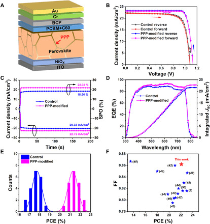
(A) Device architecture of the PPP-modified PSCs. (B) Champion J-V curves obtained in forward and reverse scans of the control and PPP-modified devices. (C) Stabilized photocurrent and SPO at 0.91 and 0.97 V for the control and PPP-modified devices, respectively. (D) EQE spectra and integrated current of the control and PPP-modified devices. (E) PCE histogram of 20 PSCs of the control and PPP-modified devices. (F) Collection of FFs versus PCEs, reported for inverted PSCs.
Table 1. Champion photovoltaic parameters of the inverted PSCs measured in different scan directions under standard AM 1.5 illumination (100 mW cm−2).
| Device | Scanning direction | Voc (V) | Jsc (mA cm−2) | FF | PCE (%) | Hysteresis factor* |
| Control | Forward | 1.078 | 22.20 | 0.755 | 18.08 | 2.90 |
| Reverse | 1.082 | 22.32 | 0.770 | 18.62 | ||
| PPP-modified | Forward | 1.131 | 23.14 | 0.837 | 21.91 | 0.90 |
| Reverse | 1.131 | 23.24 | 0.841 | 22.11 |
Origin of the improved performance and device physics
We tested the steady-state photoluminescence (SSPL) and time-resolved photoluminescence (TRPL) to analyze the carrier recombination dynamics as presented in Fig. 4 (A and B) and listed the corresponding data in Table 2. The SSPL intensity of the PPP-modified perovskite film exhibits an obvious enhancement compared to that of the control. Concurrently, the PL peak position of the PPP-modified film displays a blue shift from 780 (control device) to 775 nm. These results provide strong evidence that the PPP molecules can effectively mitigate the trap density and act to passivate GBs and surface defects, due to their strong interaction with perovskite as supported by the XPS and FTIR results. We further investigated the origin of the improved photovoltaic performance by performing TRPL measurements to study the carrier transport and recombination at the perovskite layer (Fig. 4B). To evaluate the TRPL data, we applied a kinetic model described in our previous study (51). For both films, we observe two features: a rapid decay within the first 50 ns followed by an almost monoexponentially slower decay. The fast decay at early times has been attributed to initial carrier trapping, whereas hole transfer, the following slower decay, is caused by nonradiative recombination (51). Considering bulk recombination, we derive for the target device a first-order rate constant for nonradiative carrier recombination of k1 = 5.3 × 10⁵ s−1 corresponding to a lifetime of τ = 941.7 ns, while the respective values for the control film are k1 = 1.61 × 10⁶ s−1 and τ = 310.8 ns. This indicates that the PPP modification of the perovskite film suppresses nonradiative carrier recombination, thus improving the photovoltaic metrics. Note, however, that surface recombination of charge carriers also yields a first-order rate law (51), rendering it difficult to distinguish between surface and bulk recombination by this kinetic analysis.
Fig. 4. Effects of PPP modification on the electrical effects of perovskite films.
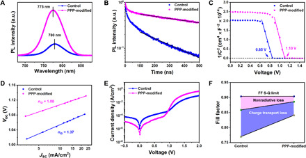
(A) SSPL and (B) TRPL spectra of the control and PPP-modified perovskite films. (C) 1/C2 versus applied voltage plots (Mott-Schottky) in the control and PPP-modified PSCs. (D) Voc plotted against the logarithm of Jsc in the device. (E) Dark J-V curves of the control and PPP-modified PSCs. (F) The device FF S-Q limit consists of charge-transport loss (blue area) and nonradiative loss (pink area). The deep yellow and olive green circles represent the measured FF and the maximum FF without charge-transport loss, respectively.
Table 2. Comparison of electrical parameters.
The trap density and charge carrier mobilities obtained for electron-only and hole-only devices with control and PPP-modified PSCs and series resistance (Rs), shunt resistance (Rsh), ideality factor (nID), and nonradiative carrier recombination lifetime (τ) for the control and PPP-modified PSCs.
| Device | Trap density (cm−3) | Mobility (cm2 V−1 s−1) | μh/μe |
Rs (ohm·cm2) |
Rsh (ohm·cm2) |
nID | τ (ns) | ||
| Electron | Hole | Electron | Hole | ||||||
| Control | 1.32 × 10¹⁶ | 4.85 × 10¹⁵ | 1.69 | 4.16 | 2.46 | 6.31 | 3,003 | 1.37 | 310.8 |
| PPP-modified | 3.87 × 10¹⁵ | 3.70 × 10¹⁵ | 14.76 | 15.94 | 1.08 | 1.30 | 15,220 | 1.08 | 941.7 |
To quantitatively investigate the PPP polymer passivation effects in perovskites, we characterize the trap density and carrier mobility by measuring the space charge–limited current. The PPP-modified devices show lower electron and hole trap densities than the control devices, which most likely results from the passivation effect of the surface or interface defects by the PPP polymer (Table 2 and fig. S16). The calculated electron mobility of the PPP-modified device is increased to 14.76 cm2 V−1 s−1 compared with that of the control device (1.69 cm2 V−1 s−1). The hole mobility also increases from 4.16 cm2 V−1 s−1 for the control device to 15.94 cm2 V−1 s−1 for the PPP-modified device. Moreover, Mott-Schottky analyses were undertaken to evaluate the built-in potential (Vbi) (Fig. 4C). The value of Vbi of the PPP-modified PSC determined is 1.10 V, which is larger than that of the control device (0.85 V). Thus, the PPP-modified device shows higher carrier mobility, more balanced carrier transportation, and a higher Vbi value, demonstrating the substantial benefits from modifying perovskite by PPP.
We further determined the effect of PPP on the ideality factor of our PSCs. The carrier recombination mechanism can be investigated by studying the current and voltage dependencies under different light intensities for the control and PPP-modified devices (fig. S17). The slope of the kBT/q unit determines whether Voc loss is predominated by trap-induced nonradiative recombination (where kB is the Boltzmann constant, T is the thermodynamic temperature, and q is the electron charge). The slope of Voc versus light intensity reduces from 1.31 kBT/q (control) to 1.08 kBT/q (PPP-modified), suggesting a reduction of trap-induced recombination under open-circuit conditions. Because of the power law Jsc ∝ Iα (where α is an exponential factor and I is the light intensity), the dependence of Jsc on light intensity can be identified. The calculated α values are 0.957 and 0.998 for the control and PPP-modified PSCs, respectively, illustrating a slight decrease in bimolecular recombination under short-circuit conditions. Furthermore, the ideality factor nID is quantized from the slope of the Voc versus lg (Jsc) plot based on Eq. 1
| (1) |
where J0 is the saturation current density at reverse bias. The calculated nID value of the control device is 1.37. The calculated nID value of the PPP-modified device decreased significantly to 1.08 (Fig. 4D). This value is very low, indicating that the trap-induced recombination is significantly suppressed.
We also study the energy band structure of the PPP-modified PSC (figs. S18 and S19). The calculated EF values of the control and PPP-modified devices are 4.61 and 4.49 eV, respectively. A significant upshift in the EF level of the PPP-modified film in devices attests to its enhanced properties as an n-type film (8). The more the properties of a perovskite film approach n-type, the more substantially the electron traps are filled, which can result in a further reduction in the reorganization events caused by the traps. As a result, the PPP-modified perovskite layer has a better band alignment with the ETL and HTL, which is beneficial toward Voc improvement, Rs decrease, and charge transfer.
To explain the improvement in FF, we measure the dark current curve because the FF is a parameter that is strongly influenced by resistance losses (Fig. 4E). The reverse saturation current and turn-on voltage of the PPP-modified device are reduced compared with that of the control device. The Rs value for the PPP-modified device decreases from 6.31 (control device) to 1.30 ohm·cm2, which we attribute to the improved quality of the perovskite film and better band alignment of the device. On the other hand, the Rsh values for the PPP-modified and control device are 15,220 and 3003 ohm·cm2, respectively. The increase in Rsh value is mainly due to the inhibition of current leakage induced by surface defects (the Rs and Rsh values are obtained from the Voc/Jsc ratio and the dark J-V curve). Furthermore, nonradiative carrier recombination and charge-transport losses are the two main reasons reducing the FF value below the S-Q limit (52). Neglecting charge-transport losses, we derive the maximum FF value (FFmax) from Eq. 2 (53)
| (2) |
| (3) |
| (4) |
where rs and rsh are the normalized resistances, given by rs = Jsc Rs/Voc and rsh = Jsc Rsh/Voc, respectively. As shown in Fig. 4F, FFmax values are 0.859 and 0.886 for the control and PPP-modified devices, respectively. The nonradiative loss for the PPP-modified device is suppressed because the PPP polymer passivates defects in the perovskite film. If both the nonradiative loss and charge-transport loss are considered, the empirical Eqs. 3 and 4 should be adopted (15), and we calculate that the FF values of the control and PPP-modified devices are 0.730 and 0.858, respectively. The calculated FF value agrees with the measured FF value, the difference being less than 6%. Compared to the control device, the charge-transport loss in the PPP-modified device is also clearly reduced owing to the increased carrier mobility, as shown above. These results confirmed that the 3D PPP polymer not only inhibits nonradiative recombination but also improves charge transport in the device.
Enhanced device stability
First, we study the environmental stability of the device. The control perovskite film shows an enhanced degradation compared with the PPP-modified perovskite film after aging for 240 hours at 85°C and 40% ambient RH (figs. S20 and S21). The presence of GBs is the main source of perovskite film decomposition in humid environment since moisture penetrates the perovskite crystal through the GBs, accelerating its destruction (31). The enhanced environmental stability can be attributed to the increased hydrophobicity of the perovskite film surface after the introduction of the PPP polymer (fig. S22). We also study the long-term stability of PSCs without encapsulation. When the device is stored in a 40% RH air environment for 6000 hours, the normalized PCE of the modified device is stable at exhibiting approximately 93% of its original value while the control device declines to ~73% of its original PCE (Fig. 5A). The relatively stable PCE of the PPP-modified perovskite film indicates that it has fewer internal defects than the control device’s film, mainly due to the protection of the perovskite crystals by the naturally hydrophobic PPP polymer that form a core-shell structure (Fig. 2E), providing a strong resistance to humidity.
Fig. 5. Stability.
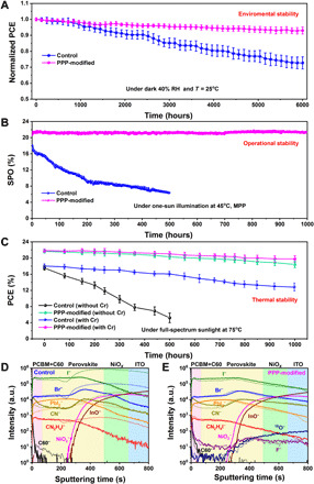
(A) Air stability for the nonencapsulated control and PPP-modified devices (the average PCE is obtained from 10 devices of each type of device, and the error bars represent the SD of the devices). (B) Maximum power point (MPP) tracking of encapsulated PSCs with and without PPP-modified in air under one-sun illumination at 45°C. (C) Thermal stability of encapsulated control and PPP-modified devices. The devices were illuminated under full-spectrum sunlight (no UV filter) at 75°C in air under open-circuit conditions, and their output photovoltaic power was determined by recording J-V curves at regular time intervals. The plotted data points present averages for the 10 cells. ToF-SIMS depth profiles of (D) control and (E) PPP-modified electrodeless PSC devices before (solid line) and after (short dashed line) thermal aging at 75°C and full-spectrum sunlight for 300 hours in the N2 atmosphere.
The PPP passivation treatment also improves the photo-, thermal, and operational stability of the PSCs. The long-term operational stability of the encapsulated CsMAFA-based PSCs with and without PPP incorporation was investigated with maximum power point tracking under one-sun illumination (45°C, in air, 100 mW/cm2) as depicted in Fig. 5B. The SPO of the control device only retains ~36% after 500 hours of operation, while the SPO of the PPP-modified device is almost unchanged after continuous operation for 1000 hours. In addition, the PCE evaluation of encapsulated devices aged under one-sun illumination at 75°C has been recorded and is exhibited in Fig. 5C. The control device with Cr interlayer maintains approximately 71% of the initial PCE for 1000 hours, whereas the control device without Cr interlayer retains only approximately 30% for 500 hours. Thus, the result demonstrates that the Cr interlayer has a positive effect on the long-term stability. Cr effectively shields gold electrode contact from detrimental reactions with oxidizing and halide-forming iodide species (54). When there is a Cr interlayer, the rate of reduction in stability witnessed under such harsh conditions is much slower for the PPP-modified device in comparison to the control device. Specific points of data are shown in fig. S23 for the most stable and highest PCE device. The PPP-modified device impressively maintains 91% of its initial efficiency of ~22% after 1000 hours, whereas the control device retains only 71% of its initial efficiency of ~18%. Our PPP-modified PSC compares favorably with other reported results (table S4). When there is no Cr interlayer, the PPP-modified device still maintains 85% of its initial efficiency after 1000 hours.
To unveil the mechanism of the enhanced stability, we monitor the depth profiles of several key species in the control and PPP-modified devices before and after thermal aging at 75°C and full-spectrum sunlight for 300 hours under a N2 atmosphere by ToF-SIMS (Fig. 5, D and E) (55, 56). C60− is selected for following the evolution of the PCBM+C60 ETL, CN− as representing the MA+ and FA+; CN2H4I− as representing the FAI, I−, PbI2−, and Br− for the CsMAFA perovskite; 18O− and F− for the PPP polymer; NiO2− for the NiOx; and InO2− for the ITO. Figure 5D shows that the diffusion of CN−, CN2H4I−, I−, PbI2−, and Br− found in the perovskite to the NiOx HTL is obvious after aging of the control electrodeless PSC device, resulting in the rapid decomposition of the perovskite. In contrast, the outward diffusion of I− and Br− ion and all ionic groups from the perovskite is largely reduced for the PPP-modified electrodeless PSC device (Fig. 5E). The strong hydrogen bonding of F···H─N between the ─CF3 radical of the PPP polymer and FA+ and MA+ can restrain FA+ and MA+, and the C═O of the PPP polymer has strong chelation with Pb to immobilize Pb ion or ionic groups; thus, the PPP-modified device exhibits a better shielding effect compared with the control device. In addition, the thermogravimetric analysis (TGA) also manifests that the PPP-modified perovskite has a better thermal stability than the control perovskite (fig. S24). Thus, the PPP polymer inhibits ion migration in the perovskite film and thus improves the long-term illumination and thermal stability of PSCs.
DISCUSSION
In summary, a 3D star-shaped multifunctional PPP polymer has been designed to modify the perovskite film used in an inverted PSC device. The PPP molecule acts as a 3D skeleton template to control crystallization and to passivate defects at GBs and the surface, as well as to reduce nonradiative recombination, charge-transport losses, and ion migration. Consequently, the PPP-modified inverted PSC obtains an optimal 22.1% efficiency and a very high FF value of 0.862. We also used a modified detailed balance model (57) to confirm that the loss of FF (0.862) in the PPP-modified device with reference to its S-Q limit (0.904) is predominantly caused by the defect-induced recombination rather than by Rs and Rsh (as detailed in fig. S25 and table S5). If nonradiative carrier recombination was controlled by the Shockley-Read-Hall bulk mechanism, the dominating factor Voc that drops from its S-Q limiting value of 1.32 V to the observed values of 1.10 V would correspond to an FF value of 0.820, which is below the measured value of 0.862. Consequently, surface recombination is likely to be the dominant recombination mechanism in the PPP-modified device. Thus, it appears feasible to further boost the FF close to its S-Q limit of 0.904 by passivating defects in interfaces. Regarding the stability, the modified device exhibits a significant enhancement in ambient air, retaining more than 93% of its initial efficiency after 6000 hours of exposure to air with 40% RH. The encapsulated device with PPP modification likewise exhibits a remarkable improvement of the operational and thermal stability, operating at maximum power point for 1000 hours under continuous one-sun illumination at 45°C, without efficiency loss. Thus, introducing the star-shaped and plurifunctional molecule in the perovskite films greatly improves its performance in particular in inverted PSC configuration, opening a new direction for advancements in the practical deployment of these solar cells.
MATERIALS AND METHODS
Materials
Nickel nitrate hexahydrate [Ni(NO3)2·6H2O, 99.999%], chlorobenzene (CB; 99.8%), anhydrous dimethyl sulfoxide (DMSO; 99.8%), and N,N-dimethylformamide (DMF; 99.8%) were purchased from Sigma-Aldrich. All photovoltaic materials were purchased from Xi’an Polymer Light Technology Corp. and did not require further purification. 3-Chloropropyltrimethoxysilane, pentamethyldiethylenetriamine (PMDETA), trifluoroethyl methacrylate (TFEMA), methyl methacrylate (MMA), and copper (I) chloride (CuCl) were purchased from Aladdin.
Materials synthesis
The synthesis process of the PPP polymer [weight-average molecular weight (Mw ≈ 1.47 × 10⁵)] was divided into two steps. (i) For the synthesis of octa(γ-chloropropyl) silsesquioxane [POSS-(Cl)8], concentrated hydrochloric acid (8 ml), 3-chloropropyltrimethoxysilane (10 ml), and methanol (200 ml) were mixed in a 500-ml round-bottomed flask and then quickly stirred for 5 days in a 40°C oil bath to complete hydrolysis. The obtained product was washed multiple times with methanol and dried under vacuum to yield a white powder. (ii) For the synthesis of PPP polymer, the synthesis procedures were carried out using POSS-(Cl)8 as radical initiator in a one-pot, two-step atom transfer radical polymerization process. In this process, the flask was continuously flowed with dry N2 to remove O2. Then, POSS-(Cl)8 (0.20 g), toluene (20 ml), TFEMA (20 ml), PMDETA (0.12 ml), and CuCl (0.02 g) were mixed in the flask. The flask was put into an oil bath equipped with magnetic stirring bar at 110°C. After the reaction proceeded for 24 hours, the same volume of the MMA monomer was added into the flask, and the reaction was continued for 24 hours. After 48 hours, the flask was cooled in ice water to terminate the polymerization reaction. The mixture was then poured into tetrahydrofuran for dilution, filtered through an alumina column to remove the catalyst, and then poured into a tenfold methanol-water mixed solvent. After being filtered and dried under a reduced pressure at 50°C for 12 hours, the final product PPP polymer was obtained. The synthesis process of this molecule is not complicated and can be prepared on a large scale.
Nickel oxide nanoparticles were synthesized according to a previous method (58). The CsMAFA triple-cation perovskite precursor solution was prepared by mixing lead iodide (PbI2; 1.30 M), cesium iodide (CsI; 0.07 M), lead bromide (PbBr2; 0.21 M), methylammonium bromide (MABr; 0.21 M), and formamidine iodide (FAI; 1.19 M) in a mixed anhydrous solvent of DMF/DMSO (4/1, v/v) and was stirred overnight (59).
Inverted solar cell fabrication (p-i-n)
ITO glasses were washed twice with ethanol in an ultrasonic bath for 15 min. NiOx (20 mg ml−1 in H2O) was spin-coated on dry and ultraviolet (UV)–treated ITO at 2000 rpm for 40 s and then heated at 100°C for 10 min. The thickness of the NiOx film was approximately 20 nm. The coated ITO was then moved to a glove box. The perovskite solution was spin-coated on the NiOx HTL according to a procedure where the spin-coating speed and duration were increased from 1000 rpm for 10 s to 6000 rpm for 30 s. A total of 110 μl of the PPP polymer with various concentrations (0, 0.04, 0.1, 0.6, and 1.0 mg ml−1) of the CB antisolvent was deposited for 15 s before the end of the procedure, and then the perovskite solution was annealed at 100°C for 20 min to obtain the bright perovskite film with a thickness of 750 nm. After that, 20 mg of PCBM (99% purity) and 5 mg of fullerene (C60, 99.5% purity) were dissolved in 1 ml of CB and spin-coated on the perovskite film at 3000 rpm for 30 s, and then the ETL films were annealed on a 60°C heating stage for 10 min. The thickness of the ETL is approximately 45 nm. After cooling to room temperature, the BCP solution (0.5 mg ml−1 in isopropanol) was spin-coated at 5800 rpm for 30 s. Last, the fabrication of the devices was accomplished by thermally evaporating chromium (Cr; 5 nm) and gold (Au; 100 nm) electrodes under a vacuum of 2 × 10⁻⁶ mbar (0.1 cm2 effective area).
Solar cell characterization
The contact angles were obtained by a DSA100 instrument (KRUSS, Germany). The SEM images of the perovskite films and cross-sectional devices were obtained using a FEI Helios G4 CX system. The TEM images were obtained with a FEI Talos F200X microscope operated with a 200-kV electron gun. The XRD patterns of the perovskite films were gained by Cu Kα radiation from a PANAlyticalX’pert PRO diffractometer equipped with a diffracted beam monochromator. The XPS measurements were performed on a Kratos Axis Supra spectrometer. The ultraviolet photoelectron spectroscopy (UPS) of the perovskite films was obtained by a Shimadzu Kratos photoelectron spectrometer with a nonmonochromatic He Iα photon source (hν = 21.22 eV). The J-V curves of the PSCs were obtained under AM 1.5 G (100 mW cm−2) solar illumination with a Newport solar simulator, and the scan rate corresponding to the curve was 0.05 V s−1. The EQE was obtained with a Newport system (1600 W) using monochromatic incident light in director current mode (60). The SSPL and TRPL spectra were obtained by an Edinburgh Instruments FLS980 fluorescence spectrometer. The absorption of the thin films was obtained using a PerkinElmer Lambda 35 UV-vis spectrophotometer. Mott-Schottky analyses were carried out on an electrochemical workstation (Chenhua 760) in a voltage range of 0 to 1.5 V under dark conditions. The FTIR spectra were measured on a Jasco FTIR-6100 spectrometer in a wavelength range of 4000 to 650 cm−1. The 1H-NMR measurements were performed by a Bruker AVANCE-300 instrument. TGA was performed by a METTLER TGA/DSC 3+ analyzer. GPC was performed with a Waters 1515 system, and the selected solvent was tetrahydrofuran. The ToF-SIMS was measured by a ToF-SIMS 5-100 instrument (ION-TOF GmbH, Germany). The depth profiling was obtained through a 10-keV Ar-cluster sputtering beam raster of 300 μm by 300 μm area.
Stability test
The moisture stability measurements of the pristine and PPP-modified perovskite films were performed at 40% RH and 85°C. The moisture stability measurements of the nonencapsulated solar cells were implemented in 40% RH and 25°C under dark condition. The PCEs of the devices were periodically obtained under AM 1.5 G simulated sunlight illumination in ambient air. The complete PSCs could be encapsulated in a N2 glove box with a cover glass and UV adhesive (LT-U001, Lumtec). The operational stability of the encapsulated cells was measured at 45°C under a white light-emitting diode lamp with a 16-channel, thin-film photovoltaic maximum power point tracking test system (YH-VMPP-16). The photo- and thermal stability of the encapsulated devices were measured by using the Newport solar simulator under open-circuit conditions. The UV filter was not used during the aging process. For J-V characterization, the devices were taken out of the aging chamber and then cooled and tested at different time intervals.
Acknowledgments
We thank C. K. Graetzel for valuable help with correcting the manuscript, F. Eickemeyer for fruitful discussion, A. Krishna for TRPL fitting, and the members from the Analytical & Testing Center of Northwestern Polytechnical University for the help of SEM, TEM, XPS, and UPS characterization. Funding: This research is supported by the Key Research and Development Program from Shaanxi Province (2020GXLH-Z-025), the Shaanxi International Cooperation Project (2020KWZ-018), the Research Fund of the State Key Laboratory of Solidification Processing (NPU), China (Grant No. 2021-QZ-02), and the Fundamental Research Funds for the Central Universities (3102019ghxm003, 3102019JC005, and 3102019ghjd001). H.Z., S.M.Z., and M.G. are grateful for financial support from the European Union’s Horizon 2020 research and innovation programme under grant agreement 881603 (GRAPHENE FLAGSHIP Core 3). Author contributions: Xuanhua Li and Q.C. proposed the experimental ideas, designed the experiments, and wrote the manuscript. J.Y., J.H., S.W., B.G., J.Z., and Xiaoqiang Li conducted the device/sample fabrication, optimization, and characterizations. Y.L. and X.M. synthesized the PPP polymer. T.X., Z.W., and W.E.I.S. performed the modified detailed balance model to study the FF loss. Q.C., M.G., S.M.Z., and H.Z. analyzed the data and revised the manuscript. Competing interests: The authors declare that they have no competing interests. Data and materials availability: All data needed to evaluate the conclusions in the paper are present in the paper and/or the Supplementary Materials. Additional data related to this paper may be requested from the authors
SUPPLEMENTARY MATERIALS
Supplementary material for this article is available at http://advances.sciencemag.org/cgi/content/full/7/28/eabg0633/DC1
REFERENCES AND NOTES
- 1.Li X., Zhang F., He H., Berry J. J., Zhu K., Xu T., On-device lead sequestration for perovskite solar cells. Nature 578, 555–558 (2020). [DOI] [PubMed] [Google Scholar]
- 2.Yang M., Li Z., Reese M. O., Reid O. G., Kim D. H., Siol S., Klein T. R., Yan Y., Berry J. J., van Hest M. F. A. M., Zhu K., Perovskite ink with wide processing window for scalable high-efficiency solar cells. Nat. Energy 2, 17038 (2017). [Google Scholar]
- 3.Burschka J., Pellet N., Moon S. J., Humphry-Baker R., Gao P., Nazeeruddin M. K., Grätzel M., Sequential deposition as a route to high-performance perovskite-sensitized solar cells. Nature 499, 316–319 (2013). [DOI] [PubMed] [Google Scholar]
- 4.Dong Q., Fang Y., Shao Y., Mulligan P., Qiu J., Cao L., Huang J., Electron-hole diffusion lengths & >175 μm in solution-grown CH3NH3PbI3 single crystals. Science 347, 967–970 (2015). [DOI] [PubMed] [Google Scholar]
- 5.Niu T., Lu J., Munir R., Li J., Barrit D., Zhang X., Hu H., Yang Z., Amassian A., Zhao K., Liu S. F., Stable high-performance perovskite solar cells via grain boundary passivation. Adv. Mater. 30, 1706576 (2018). [DOI] [PubMed] [Google Scholar]
- 6.Best Research Cell Efficiency Records, Nation Renewable Energy Laboratory (NREL) (2021); www.nrel.gov/pv/cell-efficiency.html.
- 7.Yoo J. J., Seo G., Chua M. R., Park T. G., Lu Y., Rotermund F., Kim Y.-K., Moon C. S., Jeon N. J., Correa-Baena J.-P., Bulović V., Shin S. S., Bawendi M. G., Seo J., Efficient perovskite solar cells via improved carrier management. Nature 590, 587–593 (2021). [DOI] [PubMed] [Google Scholar]
- 8.Zheng X., Hou Y., Bao C., Yin J., Yuan F., Huang Z., Song K., Liu J., Troughton J., Gasparini N., Zhou C., Lin Y., Xue D.-J., Chen B., Johnston A. K., Wei N., Hedhili M. N., Wei M., Alsalloum A. Y., Maity P., Turedi B., Yang C., Baran D., Anthopoulos T. D., Han Y., Lu Z.-H., Mohammed O. F., Gao F., Sargent E. H., Bakr O. M., Managing grains and interfaces via ligand anchoring enables 22.3%-efficiency inverted perovskite solar cells. Nat. Energy 5, 131–140 (2020). [Google Scholar]
- 9.Min H., Kim M., Lee S.-U., Kim H., Kim G., Choi K., Lee J. H., Seok S. I., Efficient, stable solar cells by using inherent bandgap of α-phase formamidinium lead iodide. Science 366, 749–753 (2019). [DOI] [PubMed] [Google Scholar]
- 10.Schulz P., Cahen D., Kahn A., Halide perovskites: Is it all about the interfaces? Chem. Rev. 119, 3349–3417 (2019). [DOI] [PubMed] [Google Scholar]
- 11.Jung E. H., Jeon N. J., Park E. Y., Moon C. S., Shin T. J., Yang T.-Y., Noh J. H., Seo J., Efficient, stable and scalable perovskite solar cells using poly(3-hexylthiophene). Nature 567, 511–515 (2019). [DOI] [PubMed] [Google Scholar]
- 12.Jiang Q., Zhao Y., Zhang X., Yang X., Chen Y., Chu Z., Ye Q., Li X., Yin Z., You J., Surface passivation of perovskite film for efficient solar cells. Nat. Photonics 13, 460–466 (2019). [Google Scholar]
- 13.Qi B., Wang J., Fill factor in organic solar cells. Phys. Chem. Chem. Phys. 15, 8972–8982 (2013). [DOI] [PubMed] [Google Scholar]
- 14.Mundhaas N., Yu Z. J., Bush K. A., Wang H.-P., Häusele J., Kavadiya S., McGehee M. D., Holman Z. C., Series resistance measurements of perovskite solar cells using Jsc–Voc measurements. Sol. RRL 3, 1800378 (2019). [Google Scholar]
- 15.Kim H. D., Ohkita H., Potential improvement in fill factor of lead-halide perovskite solar cells. Sol. RRL 1, 1700027 (2017). [Google Scholar]
- 16.Luo D., Su R., Zhang W., Gong Q., Zhu R., Minimizing non-radiative recombination losses in perovskite solar cells. Nat. Rev. Mater. 5, 44–60 (2020). [Google Scholar]
- 17.Zhang H., Nazeeruddin M. K., Choy W. C. H., Perovskite photovoltaics: The significant role of ligands in film formation, passivation, and stability. Adv. Mater. 31, 1805702 (2019). [DOI] [PubMed] [Google Scholar]
- 18.Bai Y., Meng X., Yang S., Interface engineering for highly efficient and stable planar p-i-n perovskite solar cells. Adv. Energy Mater. 8, 1701883 (2018). [Google Scholar]
- 19.Gao F., Zhao Y., Zhang X., You J., Recent progresses on defect passivation toward efficient perovskite solar cells. Adv. Energy Mater. 10, 1902650 (2020). [Google Scholar]
- 20.Liu S., Guan Y., Sheng Y., Hu Y., Rong Y., Mei A., Han H., A review on additives for halide perovskite solar cells. Adv. Energy Mater. 10, 1902492 (2020). [Google Scholar]
- 21.Zhang F., Zhu K., Additive engineering for efficient and stable perovskite solar cells. Adv. Energy Mater. 10, 1902579 (2020). [Google Scholar]
- 22.Lee J. W., Dai Z., Lee C., Lee H. M., Han T. H., De Marco N., Lin O., Choi C. S., Dunn B., Koh J., Di Carlo D., Ko J. H., Maynard H. D., Yang Y., Tuning molecular interactions for highly reproducible and efficient formamidinium perovskite solar cells via adduct approach. J. Am. Chem. Soc. 140, 6317–6324 (2018). [DOI] [PubMed] [Google Scholar]
- 23.Lin Y.-H., Sakai N., Da P., Wu J., Sansom H. C., Ramadan A. J., Mahesh S., Liu J., Oliver R. D. J., Lim J., Aspitarte L., Sharma K., Madhu P. K., Morales-Vilches A. B., Nayak P. K., Bai S., Gao F., Grovenor C. R. M., Johnston M. B., Labram J. G., Durrant J. R., Ball J. M., Wenger B., Stannowski B., Snaith H. J., A piperidinium salt stabilizes efficient metal-halide perovskite solar cells. Science 369, 96–102 (2020). [DOI] [PubMed] [Google Scholar]
- 24.Bai S., Da P., Li C., Wang Z., Yuan Z., Fu F., Kawecki M., Liu X., Sakai N., Wang J. T.-W., Huettner S., Buecheler S., Fahlman M., Gao F., Snaith H. J., Planar perovskite solar cells with long-term stability using ionic liquid additives. Nature 571, 245–250 (2019). [DOI] [PubMed] [Google Scholar]
- 25.Noel N. K., Abate A., Stranks S. D., Parrott E. S., Burlakov V. M., Goriely A., Snaith H. J., Enhanced photoluminescence and solar cell performance via lewis base passivation of organic–inorganic lead halide perovskites. ACS Nano 8, 9815–9821 (2014). [DOI] [PubMed] [Google Scholar]
- 26.Wang R., Xue J., Meng L., Lee J.-W., Zhao Z., Sun P., Cai L., Huang T., Wang Z., Wang Z.-K., Duan Y., Yang J. L., Tan S., Yuan Y., Huang Y., Yang Y., Caffeine improves the performance and thermal stability of perovskite solar cells. Joule 3, 1464–1477 (2019). [Google Scholar]
- 27.Chiang C.-H., Wu C.-G., Bulk heterojunction perovskite-PCBM solar cells with high fill factor. Nat. Photonics 10, 196–200 (2016). [Google Scholar]
- 28.Bi D., Yi C., Luo J., Décoppet J.-D., Zhang F., Zakeeruddin S. M., Li X., Hagfeldt A., Grätzel M., Polymer-templated nucleation and crystal growth of perovskite films for solar cells with efficiency greater than 21%. Nat. Energy 1, 16142 (2016). [Google Scholar]
- 29.Han T. H., Lee J. W., Choi C., Tan S., Lee C., Zhao Y., Dai Z., De Marco N., Lee S. J., Bae S. H., Yuan Y., Lee H. M., Huang Y., Yang Y., Perovskite-polymer composite cross-linker approach for highly-stable and efficient perovskite solar cells. Nat. Commun. 10, 520 (2019). [DOI] [PMC free article] [PubMed] [Google Scholar]
- 30.Elmelund T., Seger B., Kuno M., Kamat P. V., How interplay between photo and thermal activation dictates halide ion segregation in mixed halide perovskites. ACS Energy Lett. 5, 56–63 (2020). [Google Scholar]
- 31.Yun J. S., Kim J., Young T., Patterson R. J., Kim D., Seidel J., Lim S., Green M. A., Huang S., Ho-Baillie A., Humidity-induced degradation via grain boundaries of HC(NH2)2PbI3 planar perovskite solar cells. Adv. Funct. Mater. 28, 1705363 (2018). [Google Scholar]
- 32.Jiang Y., Yang S.-C., Jeangros Q., Pisoni S., Moser T., Buecheler S., Tiwari A. N., Fu F., Mitigation of vacuum and illumination-induced degradation in perovskite solar cells by structure engineering. Joule 4, 1087–1103 (2020). [Google Scholar]
- 33.Li N., Luo Y., Chen Z., Niu X., Zhang X., Lu J., Kumar R., Jiang J., Liu H., Guo X., Lai B., Brocks G., Chen Q., Tao S., Fenning D. P., Zhou H., Microscopic degradation in formamidinium-cesium lead iodide perovskite solar cells under operational stressors. Joule 4, 1743–1758 (2020). [Google Scholar]
- 34.Zhao Y., Wei J., Li H., Yan Y., Zhou W., Yu D., Zhao Q., A polymer scaffold for self-healing perovskite solar cells. Nat. Commun. 7, 10228 (2016). [DOI] [PMC free article] [PubMed] [Google Scholar]
- 35.Zhang W., Camino G., Yang R., Polymer/polyhedral oligomeric silsesquioxane (POSS) nanocomposites: An overview of fire retardance. Prog. Polym. Sci. 67, 77–125 (2017). [Google Scholar]
- 36.Valero S., Soria T., Marinova N., Delgado J. L., Efficient and stable perovskite solar cells based on perfluorinated polymers. Polym. Chem. 10, 5726–5736 (2019). [Google Scholar]
- 37.Meng L., Sun C., Wang R., Huang W., Zhao Z., Sun P., Huang T., Xue J., Lee J. W., Zhu C., Huang Y., Li Y., Yang Y., Tailored phase conversion under conjugated polymer enables thermally stable perovskite solar cells with efficiency exceeding 21%. J. Am. Chem. Soc. 140, 17255–17262 (2018). [DOI] [PubMed] [Google Scholar]
- 38.Zhang C.-C., Wang Z.-K., Yuan S., Wang R., Li M., Jimoh M. F., Liao L.-S., Yang Y., Polarized ferroelectric polymers for high-performance perovskite solar cells. Adv. Mater. 31, 1902222 (2019). [DOI] [PubMed] [Google Scholar]
- 39.Rühle S., Tabulated values of the Shockley-Queisser limit for single junction solar cells. Sol. Energy 130, 139–147 (2016). [Google Scholar]
- 40.Wang K., Liu C., Du P., Zheng J., Gong X., Bulk heterojunction perovskite hybrid solar cells with large fill factor. Energ. Environ. Sci. 8, 1245–1255 (2015). [Google Scholar]
- 41.Wu C.-G., Chiang C.-H., Tseng Z.-L., Nazeeruddin M. K., Hagfeldt A., Grätzel M., High efficiency stable inverted perovskite solar cells without current hysteresis. Energ. Environ. Sci. 8, 2725–2733 (2015). [Google Scholar]
- 42.Chiang C. H., Wu C. G., A method for the preparation of highly oriented MAPbI3 crystallites for high-efficiency perovskite solar cells to achieve an 86% fill factor. ACS Nano 12, 10355–10364 (2018). [DOI] [PubMed] [Google Scholar]
- 43.Bai Y., Lin Y., Ren L., Shi X., Strounina E., Deng Y., Wang Q., Fang Y., Zheng X., Lin Y., Chen Z.-G., Du Y., Wang L., Huang J., Oligomeric silica-wrapped perovskites enable synchronous defect passivation and grain stabilization for efficient and stable perovskite photovoltaics. ACS Energy Lett. 4, 1231–1240 (2019). [Google Scholar]
- 44.Chen H., Wei Q., Saidaminov M. I., Wang F., Johnston A., Hou Y., Peng Z., Xu K., Zhou W., Liu Z., Qiao L., Wang X., Xu S., Li J., Long R., Ke Y., Sargent E. H., Ning Z., Efficient and stable inverted perovskite solar cells incorporating secondary amines. Adv. Mater. 31, 1903559 (2019). [DOI] [PubMed] [Google Scholar]
- 45.Yang S., Chen S., Mosconi E., Fang Y., Xiao X., Wang C., Zhou Y., Yu Z., Zhao J., Gao Y., Angelis F. D., Huang J., Stabilizing halide perovskite surfaces for solar cell operation with wide-bandgap lead oxysalts. Science 365, 473–478 (2019). [DOI] [PubMed] [Google Scholar]
- 46.Ru P., Bi E., Zhang Y., Wang Y., Kong W., Sha Y., Tang W., Zhang P., Wu Y., Chen W., Yang X., Chen H., Han L., High electron affinity enables fast hole extraction for efficient flexible inverted perovskite solar cells. Adv. Energy Mater. 10, 1903487 (2020). [Google Scholar]
- 47.Wang K., Wu C., Hou Y., Yang D., Ye T., Yoon J., Sanghadasa M., Priya S., Isothermally crystallized perovskites at room-temperature. Energ. Environ. Sci. 13, 3412–3422 (2020). [Google Scholar]
- 48.Wu S., Zhang J., Li Z., Liu D., Qin M., Cheung S. H., Lu X., Lei D., So S. K., Zhu Z., Jen A. K. Y., Modulation of defects and interfaces through alkylammonium interlayer for efficient inverted perovskite solar cells. Joule 4, 1248–1262 (2020). [Google Scholar]
- 49.Chen W., Wang Y., Pang G., Koh C. W., Djurišić A. B., Wu Y., Tu B., Liu F.-z., Chen R., Woo H. Y., Guo X., He Z., Conjugated polymer-assisted grain boundary passivation for efficient inverted planar perovskite solar cells. Adv. Funct. Mater. 29, 1808855 (2019). [Google Scholar]
- 50.Liu X., Cheng Y., Liu C., Zhang T., Zhang N., Zhang S., Chen J., Xu Q., 20.7% highly reproducible inverted planar perovskite solar cells with enhanced fill factor and eliminated hysteresis. Energ. Environ. Sci. 12, 1622–1633 (2019). [Google Scholar]
- 51.Su T. S., Eickemeyer F. T., Hope M. A., Jahanbakhshi F., Mladenovic M., Li J., Zhou Z., Mishra A., Yum J. H., Ren D., Krishna A., Ouellette O., Wei T. C., Zhou H., Huang H. H., Mensi M. D., Sivula K., Zakeeruddin S. M., Milic J. V., Hagfeldt A., Rothlisberger U., Emsley L., Zhang H., Gratzel M., Crown ether modulation enables over 23% efficient formamidinium-based perovskite solar cells. J. Am. Chem. Soc. 142, 19980–19991 (2020). [DOI] [PubMed] [Google Scholar]
- 52.Green M. A., Accuracy of analytical expressions for solar cell fill factors. Sol. Cells 7, 337–340 (1982). [Google Scholar]
- 53.Wang J., Zhang J., Zhou Y., Liu H., Xue Q., Li X., Chueh C.-C., Yip H.-L., Zhu Z., Jen A. K. Y., Highly efficient all-inorganic perovskite solar cells with suppressed non-radiative recombination by a lewis base. Nat.Commun. 11, 177 (2020). [DOI] [PMC free article] [PubMed] [Google Scholar]
- 54.Kaltenbrunner M., Adam G., Glowacki E. D., Drack M., Schwodiauer R., Leonat L., Apaydin D. H., Groiss H., Scharber M. C., White M. S., Sariciftci N. S., Bauer S., Flexible high power-per-weight perovskite solar cells with chromium oxide-metal contacts for improved stability in air. Nat. Mater. 14, 1032–1039 (2015). [DOI] [PubMed] [Google Scholar]
- 55.Harvey S. P., Messinger J., Zhu K., Luther J. M., Berry J. J., Investigating the effects of chemical gradients on performance and reliability within perovskite solar cells with TOF-SIMS. Adv. Energy Mater. 10, 1903674 (2020). [Google Scholar]
- 56.Cao J., Tao S. X., Bobbert P. A., Wong C. P., Zhao N., Interstitial occupancy by extrinsic alkali cations in perovskites and its impact on ion migration. Adv. Mater. 30, 1707350 (2018). [DOI] [PubMed] [Google Scholar]
- 57.Sha W. E. I., Zhang H., Wang Z. S., Zhu H. L., Ren X., Lin F., Jen A. K. Y., Choy W. C. H., Quantifying efficiency loss of perovskite solar cells by a modified detailed balance model. Adv. Energy Mater. 8, 1701586 (2018). [Google Scholar]
- 58.Zhang H., Cheng J., Lin F., He H., Mao J., Wong K. S., Jen A. K., Choy W. C., Pinhole-free and surface-nanostructured NiOx film by room-temperature solution process for high-performance flexible perovskite solar cells with good stability and reproducibility. ACS Nano 10, 1503–1511 (2016). [DOI] [PubMed] [Google Scholar]
- 59.Cao Q., Li Z., Han J., Wang S. J., Zhu J., Tang H., Li X., Li X., Electron transport bilayer with cascade energy alignment for efficient perovskite solar cells. Sol. RRL 3, 1900333 (2019). [Google Scholar]
- 60.Wang S., Li Z., Zhang Y., Liu X., Han J., Li X., Liu Z., Liu S., Choy W. C. H., Water-soluble triazolium ionic-liquid-induced surface self-assembly to enhance the stability and efficiency of perovskite solar cells. Adv. Funct. Mater. 29, 1900417 (2019). [Google Scholar]
- 61.Tan H., Jain A., Voznyy O., Lan X., Arquer F. P. G. d., Fan J. Z., Quintero-Bermudez R., Yuan M., Zhang B., Zhao Y., Fan F., Li P., Quan L. N., Zhao Y., Lu Z.-H., Yang Z., Hoogland S., Sargent E. H., Efficient and stable solution-processed planar perovskite solar cells via contact passivation. Science 355, 722–726 (2017). [DOI] [PubMed] [Google Scholar]
- 62.Hou Y., Du X. Y., Scheiner S., McMeekin D. P., Wang Z., Li N., Killian M. S., Chen H. W., Richter M., Levchuk I., Schrenker N., Spiecker E., Stubhan T., Luechinger N. A., Hirsch A., Schmuki P., Steinrück H.-P., Fink R. H., Halik M., Snaith H. J., Brabec C. J., A generic interface to reduce the efficiency-stability-cost gap of perovskite solar cells. Science 358, 1192–1197 (2017). [DOI] [PubMed] [Google Scholar]
- 63.Christians J. A., Schulz P., Tinkham J. S., Schloemer T. H., Harvey S. P., Tremolet de Villers B. J., Sellinger A., Berry J. J., Luther J. M., Tailored interfaces of unencapsulated perovskite solar cells for & >1,000 hour operational stability. Nat. Energy 3, 68–74 (2018). [Google Scholar]
- 64.Turren-Cruz S.-H., Hagfeldt A., Saliba M., Methylammonium-free, high-performance, and stable perovskite solar cells on a planar architecture. Science 362, 449–453 (2018). [DOI] [PubMed] [Google Scholar]
- 65.Chen W., Wu Y., Yue Y., Liu J., Zhang W., Yang X., Chen H., Bi E., Ashraful I., Grätzel M., Han L., Efficient and stable large-area perovskite solar cells with inorganic charge extraction layers. Science 350, 944–948 (2015). [DOI] [PubMed] [Google Scholar]
- 66.Wang Y., Chen W., Wang L., Tu B., Chen T., Liu B., Yang K., Koh C. W., Zhang X., Sun H., Chen G., Feng X., Woo H. Y., Djurišić A. B., He Z., Guo X., Dopant-free small-molecule hole-transporting material for inverted perovskite solar cells with efficiency exceeding 21%. Adv. Mater. 31, 1902781 (2019). [DOI] [PubMed] [Google Scholar]
Associated Data
This section collects any data citations, data availability statements, or supplementary materials included in this article.
Supplementary Materials
Supplementary material for this article is available at http://advances.sciencemag.org/cgi/content/full/7/28/eabg0633/DC1