

Abstract
An open source remote monitoring system is designed and built to address the needs of researchers to provide basic illuminated visual indication of laser operation for university research laboratories that are equipped with multiple types of high-powered lasers and have limited financial resources. The 3D printed remote monitoring system selectively monitors either the total current running through a laser or a TTL shutter signal to wirelessly indicate at the laboratory entrances that a laser is in use. Several lasers can be monitored in a single room and each room entrance can have its own wireless laser activity indicator. The wireless feature eliminates the expense of in-wall wiring for the system. An emergency shut off switch is included as an optional attachment. This article describes the design of the readily deployed open source laser monitoring system, including how it was built and tested for integration into a microscopy research laboratory.
Keywords: Laser, monitoring, wireless, open-source, Arduino, 3D printing
1. Introduction:
Research laboratories routinely use high powered lasers to carry out fundamental research in the biological and physical sciences. Research laboratories are rarely built for the specific laser application requirements of an experiment due to limited availability of university space and budget constraints. Frequently, potentially hazardous laser equipment is installed in retrofitted laboratory spaces, e.g., utilizing several different commercial lasers in a multi-door room that was never intended to house these advanced light sources. A wide variety of laser equipment is used because technology requirements vary depending on the experimental application and scientific domain. While the need for laser monitoring applies to many types of research entities, there is particular need in academic research, where some of the most advanced laser systems are home built. The ultrafast lasers in multiphoton laser scanning microscopy [1] are an example of Class IV laser systems that are frequently built from scratch due to their experimental nature and placed in retrofitted university lab spaces. Similarly in engineering institutes, experimental 3D metal printing testbeds are an example of home built Class IV laser systems that may not have been designed from the outset with a laser monitoring system [2]. University laboratories host a dynamic number of students and faculty involved with various experiments. These labs must employ basic laser activity monitoring to alert users to active beams and ensure proper laser use. Unfortunately, the complexity and cost of setting up a customized laser monitoring system that interfaces with all such devices and works at every entry door may be financially or structurally prohibitive for the average university research lab.
The American National Standards Institute (ANSI) provides guidance on safe laser use in various scenarios, including educational institutions [3] and research settings [4]. Laser classes are categorized into four primary levels by ANSI with further guidance provided depending on the environment. The lowest risk lasers belong to Class 1 and have no requirement for special safety measures, because they do not cause damage to the eye. Class 2 includes lasers that are only hazardous if viewed directly for an extended period. Class 3 includes lasers that can damage the eye even if viewed momentarily, while Class 4 is defined as any laser with an output power above 0.5 W due to the ease with which such power can cause harm [5]. Large universities with potentially hundreds of laser units across multiple departments have found it challenging in recent years to maintain laser safety and management programs that provide proper safety training, laser inventory, and controlled areas for performing research [6]. Safety programs at research universities must provide a means of preventing laser exposure to the eye, as the retina is the most susceptible tissue to laser damage and is consequently the most prevalent accidental injury [7]. Components of an overall safety program may include educating end users about laser warning signs and laser monitoring equipment to reduce the risk of accidental exposure to other lab members [8].
An open source remote monitoring system for laser equipment is needed to address such concerns when a viable commercial option is not available or practical, and when safety requirements are sufficiently met by relatively minimal infrastructure changes. A remote laser monitoring system can be a useful tool that can function as just one component of a more comprehensive laser safety program. It should be understood that such an open-source device is dependent on the skillset of the person assembling it, would need to be safety tested and approved by the applicable lab or university governance, and does not by itself form a complete and sufficient laser safety program or radiation safety protocol. In the proposed open source remote monitoring system, a paired laser monitor and indicator box is designed, built, and tested for continuously monitoring relevant laser status parameters and wirelessly updating a remote indicator on one or more entrances to alert occupants to active laser use (Fig. 1). The monitor and indicator housings can be produced via readily available 3D printing systems [9]. The printed circuit board (PCB) designs can be easily replicated, and the electronics design can be easily manufactured by an individual with basic electronics skills using commercially available parts. Alternatively, these steps can be contracted out to several online or in-person electronics service entities.
Fig. 1:
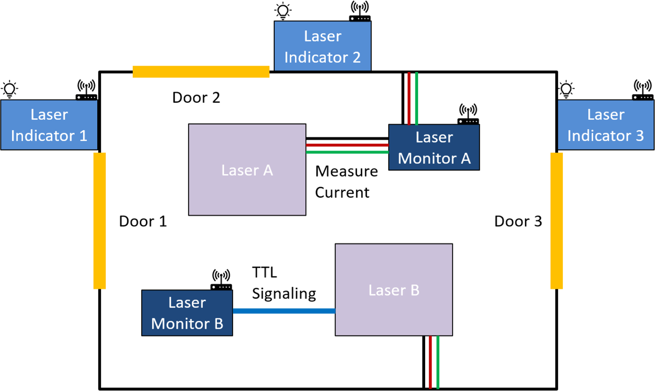
Laboratory with two lasers and multiple entrances. Monitor A is measuring primary current while Monitor B is instead awaiting a digital signal. Indicators 1–3 all receive information wirelessly from both laser monitors and update their displays at each entrance accordingly.
The laser monitoring system is designed to be compatible with most lasers that are found in research labs. This is accomplished by permitting two independent methods of measurement: monitoring the current running to the laser power supply or monitoring a programming port on the laser hardware. During the initial setup of the system, the user switches between monitoring total laser current draw with a current transformer or monitoring a laser transistor-transistor logic (TTL) signal (e.g., to represent shutter action) to remotely update a light emitting diode (LED) indicator unit at every lab entrance. While many modern lasers have a programming port that can be read out by the user, some older lasers do not have an easily accessible interface and would make use of the laser monitoring system’s ability to directly monitor the current running to the laser power supply. Each laser within the lab can be assigned a unique name that corresponds to one of the five illuminated indicators on the laser activity indicator box located outside the entrances. An optional emergency shut-off switch is integrated into the laser monitor such that each laser can be shut off quickly, if needed.
2. Materials and Methods:
2.1. Circuit Design
The circuit for the laser activity monitoring box is shown in Fig. 2, and is based on a design with the monitoring box placed between the laser equipment and the wall outlet through an in-line fuse rated to 5 A. Laser equipment power is routed through the monitoring box, with a 1000:1 current transformer monitoring the return current along the neutral line and a mains relay connected to the line voltage. The mains relay is added to permit the use of an emergency stop button inside the research lab which, upon activation, will immediately remove power from the laser equipment but maintain power to the laser monitoring box for continued communication with the activity indicator unit outside the room. The neutral line was chosen for current measurement to reduce the likelihood of a high voltage fault into the microcontroller logic circuitry. However, the relay switch needs to be placed on the line voltage to cut power to the laser, even in the event of a ground fault. A reverse biased flyback diode is placed across the relay leads to absorb transient voltage spikes during switching. The emergency stop button may not be desired if other safety measures are in place, so the emergency stop button can be enabled or disabled via a manual switch on the laser monitoring box. Power to the relay is provided by a fused 12 V AC/DC converter that also provides power to the microcontroller and logic circuitry. Various power lines are directed through terminal blocks labelled TB1 through TB4.
Fig. 2:
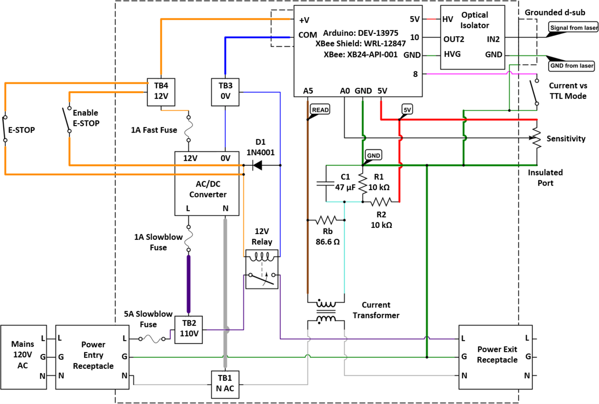
Circuit design for laser activity monitor box.
The current transformer circuit creates an oscillating low voltage waveform of up to 2.5 V that rides on top of a 2.5 V DC bias line. The microcontroller samples the resulting 0 – 5 V analog signal and calculates the waveform amplitude over a small number of cycles to determine current magnitude through the power lines running to the laser equipment. The current measurement is compared to a reference signal that is set by the user via a potentiometer during installation or routine maintenance and is referred to on the monitoring box as a sensitivity dial. As the current draw for different lasers varies and there is oftentimes a ramp up current, it is up to the user to set a current threshold that applies to their particular laser system. One method of setting this current threshold would be for the user to experimentally compare the behavior of the laser monitor as the laser transitions between different operating states and to adjust the sensitivity until it meets the requirements of the particular laser or experimental setup. This step would be accomplished during commissioning of the laser activity monitor. A trimpot is accessible on the front of the laser monitor housing that can be adjusted as needed to set the electrical current sensitivity.
A toggle switch is also monitored by the microcontroller to change the operation mode of the laser activity monitor. One mode utilizes the current transformer to measure a laser electrical current value relative to a threshold, whereas a second mode ignores the electrical current measurement and instead monitors a TTL programming signal from a D-subminiature port. This programming port can be useful in situations where the laser current is always high, but a shutter is used instead to turn the laser on or off. Various manufacturers provide serial information or equipment hardware pins that indicate the status of this shutter. The shutter status digital signal or a signal based on program status can be used to interface with the laser activity monitor and indicate that the laser is on or off. An Arduino microcontroller analyzes the laser monitoring inputs and broadcasts radiofrequency (RF) signals to indicator boxes via an XBee RF transceiver. An RF transceiver was chosen over a WiFi transceiver in order to avoid the oftentimes complex firewall issues that exist on University wireless networks.
The laser equipment is additionally protected from ground loops or high voltage transients via an optical isolator (for galvanic electrical isolation) on the D-subminiature programming port. A ground connection runs from the mains ground line to the otherwise electrically floating microcontroller subcircuit to guarantee a known reference voltage for any measurement equipment within the laser monitoring box. Without this ground connection, the inner electronics could float as high as the mains voltage while the AC/DC converter, safety relay, current transformer, and optical isolator create galvanic isolation barriers.
The circuit design for the laser activity indicator box (outside lab entry door) is shown in Fig. 3. An Arduino microcontroller selectively activates one of five LED strip lights through a transistor network to avoid running too much current through any of the on-board digital outputs. A parallel connection to the +5 VDC power rails on the microcontroller provides the current for each LED strip light. A 10 Ah battery pack provides back-up power to the indicator box in the event of a power failure and can provide +5 VDC at up to 2 A. The battery pack is continuously charged through a 5 V AC/DC wall adapter run through a USB connection. The Arduino microcontroller is outfitted with an XBee RF transceiver, via a shield, that communicates with the other XBee transceivers on the resulting wireless network that consists of the monitor boxes and indicator boxes in the research lab.
Fig. 3:
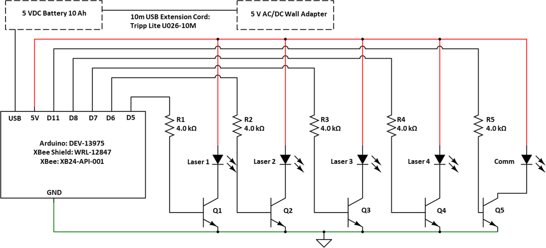
Circuit design for remote LED indicator box.
2.2. Printed Circuit Board Layout
Printed circuit boards (PCB) were designed for the laser activity monitoring system to simplify assembly of the open source model and minimize the chance of soldering mistakes. The PCB for the laser activity monitoring box is shown in Fig. 4A and is largely organized by voltage level, with a high voltage (120 V AC) area on one side of the board and two lower voltage areas on the right side of the board in the figure. Distinct ground planes are placed under the 12 V DC region and the 5 V DC region of the board to separate out the low level logic signal ground from the AC/DC output lines that have the emergency stop and relay present.
Fig. 4:
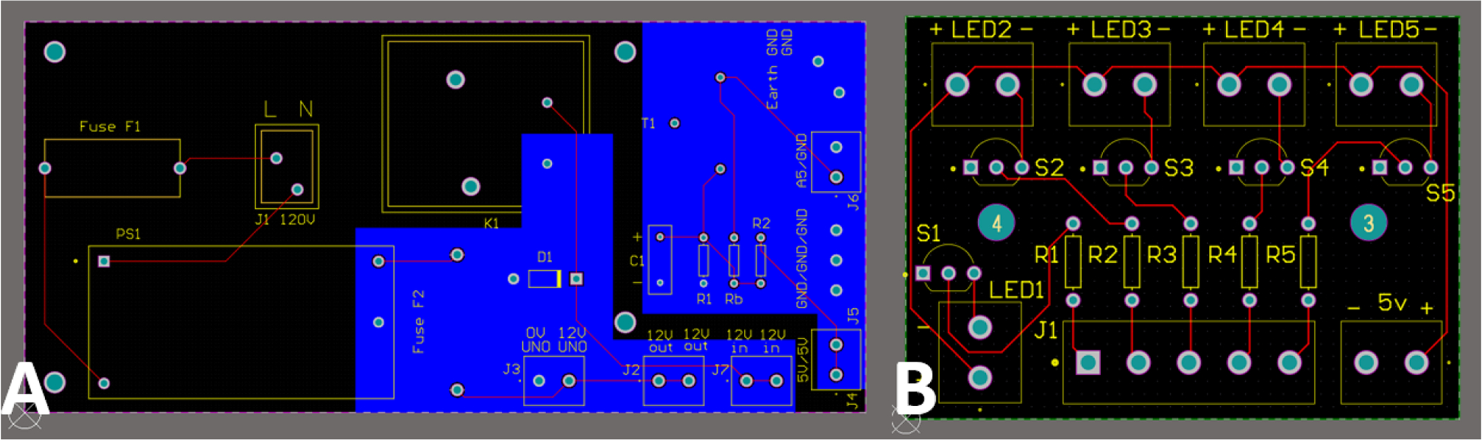
PCB layouts for laser power and TTL monitor (A) and remote LED indicator unit (B).
A smaller PCB is shown in Fig. 4B for the laser activity indicator box with a single large ground plane for all low voltage digital signals. Terminal blocks are used extensively on both boards to make it simple for the user to make connections and to facilitate replacements of various components. Trace widths of 10 mil with a 1 oz copper weight on both boards are appropriate for the anticipated current levels and extra spacing has been provided where high voltage signals are routed. The 10 mil external trace widths are appropriate for the max expected PCB trace currents of 500 mA, which is determined by analyzing the loads present on the board. The 4.5 A max high current from the actual laser does not pass through any PCB traces and is instead routed through the monitor box using insulated 12 AWG wire. A minimum 50 mil spacing is used wherever 120 V is present, and 4 mil is used for 12 V or lower.
2.3. 3D Printed Enclosures and Wire Routing
The enclosures were designed to be fabricated with standard commercially available extrusion type 3D printers allowing for an efficient custom design while eliminating the expense and time of typical custom fabrication techniques. The open source 3D printed enclosures provide mounting points, ports, and wire guides specifically designed for the specified hardware in a compact form factor. Another advantage of the 3D printing approach is the ability to produce holes in the base and the lid of the laser activity monitor box for passive cooling of the internal components. Provisions for air flow are necessary as several of the components are designed to run at elevated temperatures with high currents, including the fuses, AC/DC converter, and relay. A traditional solid construction metal enclosure has high thermal conductivity and can more readily dissipate heat, so the transition to a plastic enclosure requires at least passive cooling and would require active cooling if even higher current levels were desired.
Another benefit of using a 3D printed plastic enclosure is the inherent electrical insulation. A metal enclosure, that is safety grounded to a wall outlet ground, provides an easy way to ground any internal components or metal clad receptacles, but if the metal enclosure were not safety grounded, this would create a shock hazard to the user during a fault, as the entire enclosure is a conductor. 3D printed plastic is an electrical insulator thus inherently providing shock protection for contact with the enclosure itself. However, any internal parts or metal clad receptacles need to be explicitly safety grounded by running internal grounding wires. Additionally, the plastic enclosure does not provide electromagnetic interference (EMI) shielding, but EMI should be similar to what is already present in the room with 120 V AC cabling routed around the lab. The 3D printed laser activity monitor enclosure with wire routing is shown in Fig. 5.
Fig. 5:

Laser monitor box CAD model and wiring diagram.
2.4. Analysis Equipment and Software
Printed circuit boards are designed using Altium Designer (Altium, San Diego, CA) and 3D modeling is performed using computer aided design (CAD) software SolidWorks (Dassault Systemes, Velizy-Villacoublay, France). A Stratasys F170 Fused Deposition Modeling (FDM) 3D printer is used with acrylonitrile butadiene styrene (ABS-M30) plastic for constructing the indicator and monitoring boxes. A FLIR AX8 thermal camera (FLIR Systems, Wilsonville, OR) is used to analyze temperature distribution throughout the electronics with an accuracy of ±2 °C or 2% of reading in a range of −10 °C to +150 °C. Emissivity was set to 0.96 within the camera software to match that of 3M Scotch 88 electrical tape [10], which was placed over large sections of the electronics, wiring, and housing during thermal tests. The microcontrollers for the laser safety system are programmed using C++ in the Arduino integrated development environment (IDE).
3. Results:
3.1. Network of Laser Activity Monitoring Nodes with Paired Remote Indicators
The resulting laser safety system is composed of at least two units: a laser activity indicator unit (Fig. 6A) and a laser activity monitoring unit (Fig. 6B). The laser activity indicator is mounted just outside the laboratory entrance(s) so that a lab resident or visitor can see if the laser is currently running. Each indicator unit has LED signs that correspond to up to four unique lasers, although not all of them need be used. The microcontroller within the indicator unit is pre-programmed to watch for specific addresses being broadcast through the XBee wireless network that can be assigned to each laser in the room. Each laser activity indicator unit also has a blue LED sign labelled “Communications” to confirm ongoing data transfer to all laser monitor unit addresses that have been assigned to it. The laser activity indicator is designed to be continuously powered by a USB charging cable connected to a nearby wall outlet or computer, and it also has a 10 Ah backup battery in case of power failure. If a lab has more than one entrance, an activity indicator should be mounted outside each laboratory entrance door and assigned the same laser monitoring addresses.
Fig. 6:
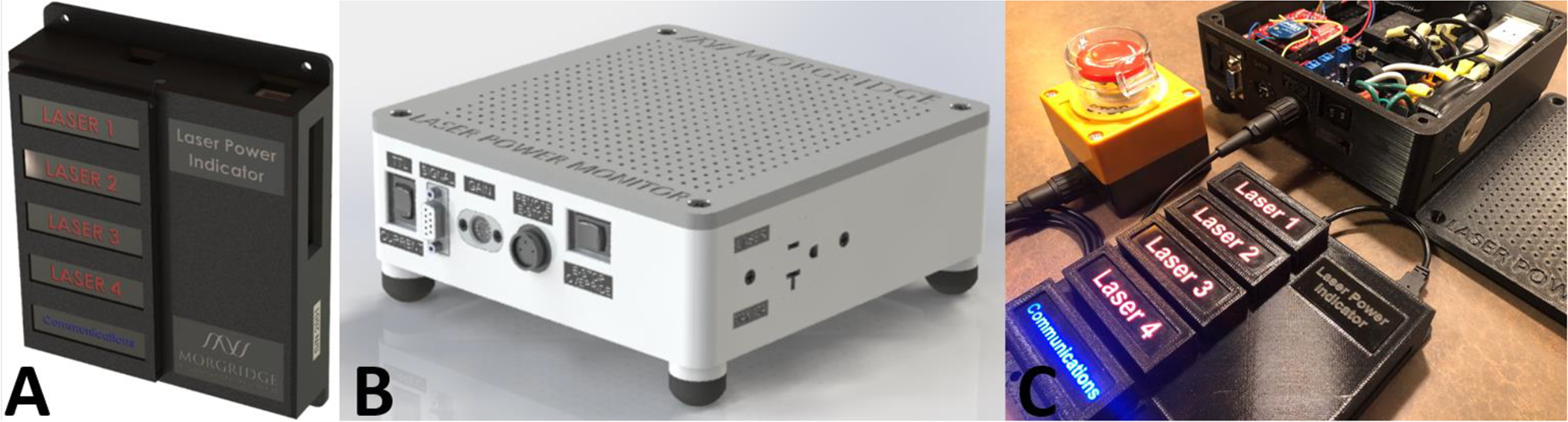
Remote indicator box (A), laser activity monitor (B) and assembled system (C).
One laser activity monitoring unit (Fig. 6B) should be connected to each laser that needs monitoring. The power to the laser can be run directly through the monitoring unit so that the current is measured and compared to a user adjustable sensitivity setting, the result of which will wirelessly update the active laser indicator LEDs on any entrances. An optional emergency stop button will cut power to the laser in this type of laser monitoring setup. Alternatively, the laser power can be run directly to a wall outlet while a 5 V TTL programming signal from the laser equipment is run to the d-subminiature port on the laser monitor to trigger the same type of wireless update to any paired laser indicator LEDs at lab entrances. Any number of lasers or other pieces of lab equipment can then be monitored inside the room by pairing with an appropriate number of remote indicator units at the entrances that are programmed to watch for updates from paired wireless addresses. The assembly of electronics inside a laser activity monitor box is shown in Fig. 6C.
3.2. Network Timing Tests
The laser activity monitor box calculates a moving average of 200 samples of the 120 V AC signal amplitude that is then compared to the sensitivity threshold set by the user with the potentiometer. The results of this comparison are further broadcast as updates to the activity indicator boxes. Multiple signal datapoints must be acquired and averaged together to determine the amplitude of the AC signal, partly due to its oscillatory nature but more importantly due to random fluctuations in power draw that are unique to each laser.
The microcontroller is in effect constantly polling the analog-to-digital converter (ADC), taking the absolute value of the result to correct for polarity, maintaining and updating an array of the 200 most recent samples, and evaluating an average of the 200 most recent results. The microcontroller is not currently programmed to operate as a real time operating system with guaranteed sampling intervals, therefore, measurements were taken to determine the mean time for the monitor box to update its moving average of the electrical current measurements used in its next wireless update. The entire process of polling the ADC module, updating the array and calculating a new average of the 200 most recent samples takes approximately 0.7 ms at a frequency of about 1400 Hz, sufficient to capture the behavior of the AC signal frequency. The randomness timing fluctuations in the code are specifically for data transmission to the listening indicator units, which occurs on a much longer timescale of 50 ms plus a random offset. Regardless of the ADC sampling rate, the activity monitors will still transmit a status update every 50 ms, plus an offset of up to 20 ms that is randomly chosen via pseudorandom number generator, to minimize the chance of data collisions at the receiver end. This update signal is used by the receiver to confirm an active communication line.
A transparent network protocol is utilized to allow simple, simultaneous laser status readings by multiple indicator units posted at lab entrances. In order to achieve this, each indicator unit runs in read-only mode, repeatedly watching for laser status updates on the unit’s pre-programmed frequency channel and local area network that should be set to unique values for each room. Each laser activity indicator box is designed to only read up to four unique lasers, although more channels could be added to the open source design with small adjustments to the hardware and enclosure, allowing for additional lasers. The current four laser maximum was chosen based on observations of laser quantities in local laboratories and to limit network congestion on the XBee wireless network. Also, each indicator box can only read one incoming signal at a time, so the chance of signal collision and data loss increases with increasing number of broadcasting laser nodes.
An experiment was performed to investigate the frequency of signal collisions for the expected laboratory set-up: four lasers with individual activity monitors and a single lab entrance with an activity indicator box. Each laser monitor in the experiment was set to broadcast an update to the network every 50 ms plus a random offset of up to 20 ms. The results (Fig. 7) show that the majority (96.6%) of broadcast signals were received without any drops, and that data collisions do occur but are relatively rare. Most disconnection events (i.e., situations in which one or more consecutive dropped signals are recorded for a given laser) resulted in only a single dropped signal (1.85%) and higher numbers of consecutive dropped signals become increasingly unlikely. No disconnection events consisting of more than six consecutively dropped signals were observed, and even these rare occurrences result in a delay of no more than 350 ms which should not cause an easily observable effect to the user. During the test with 62,932 readings, only 3.45% of signals were dropped. The timing delay during disconnection events was observed to be clustered around multiples of the base update frequency of the laser monitoring units (50 ms), thus mostly represents data collisions and missed signals.
Fig. 7:
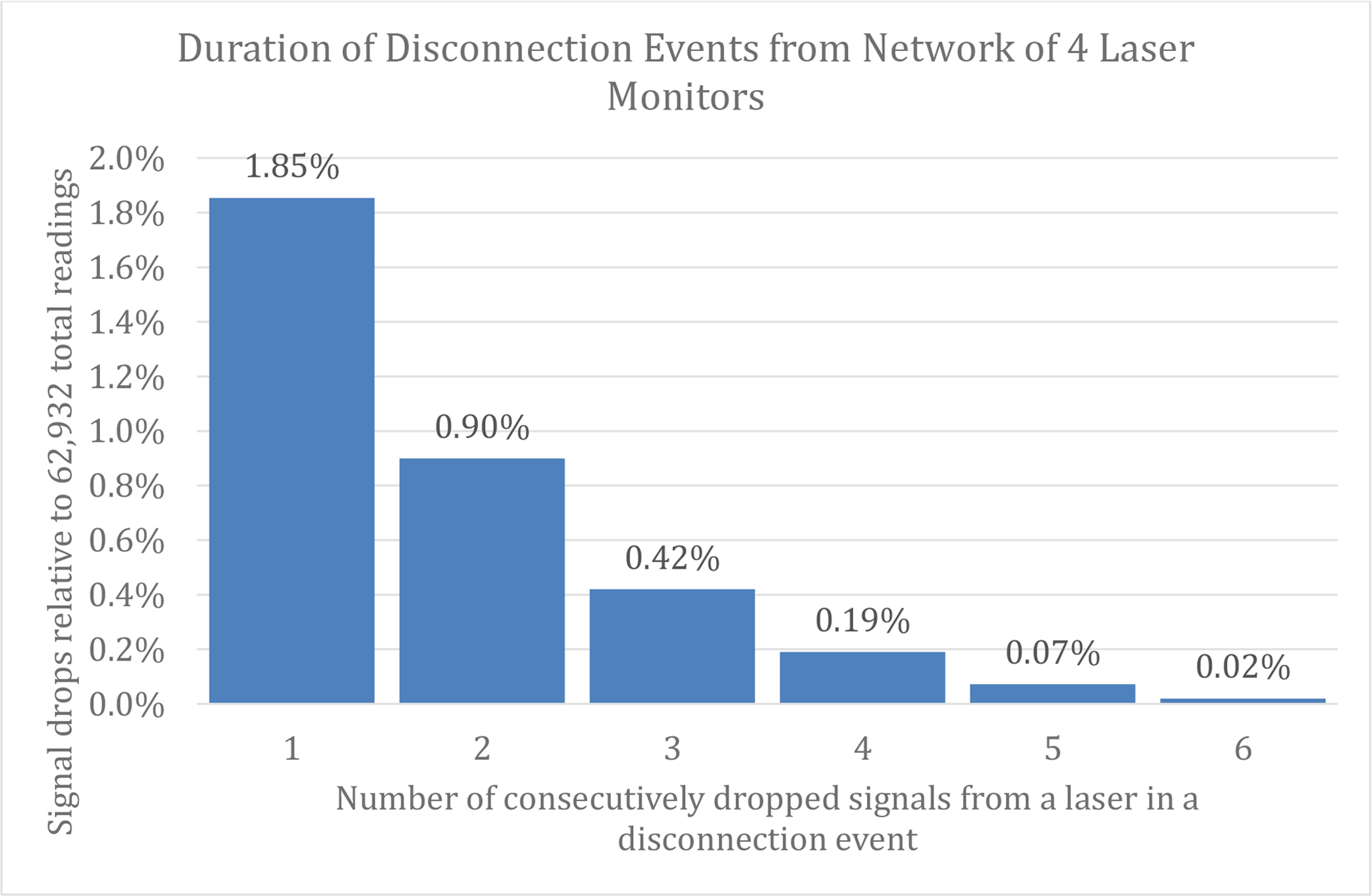
Signal delay measurements with 4 node XBee network of laser monitoring units.
3.3. Thermal Tests
Thermal tests were conducted to ensure no over-heating, given that the laser monitor is built within a fairly compact plastic enclosure. Thermal imaging was only performed on the laser activity monitor, however, due to the fact that it can be run in-line with the primary laser power and consequently captures higher electrical currents than the remote indicator system which only allows for milliamps of current. A thermal image with overlaid optical frame is shown in Fig. 8 with 4.5 A of load current after settling for one hour, demonstrating that elevated temperatures are present primarily in the vicinity of the 120 V relay and high current fuse. The microcontroller is also a warm location in the monitor box. The temperature for most of the monitor enclosure is under 40 °C and the maximum of 45.6 °C is found on the 120 V relay. The housing for the high current fuse reaches a temperature of approximately 43 °C, while the plastic wall near the fuse is at 38.5 °C. The 3D printed box material has the lowest temperature limit in the monitor box as it is composed of ABS thermoplastic. The plastic used for this project is ABS-M30 with a glass transition temperature of 108 °C and is susceptible to heat deflection at 82 °C when under a high pressure of 264 psi.
Fig. 8:
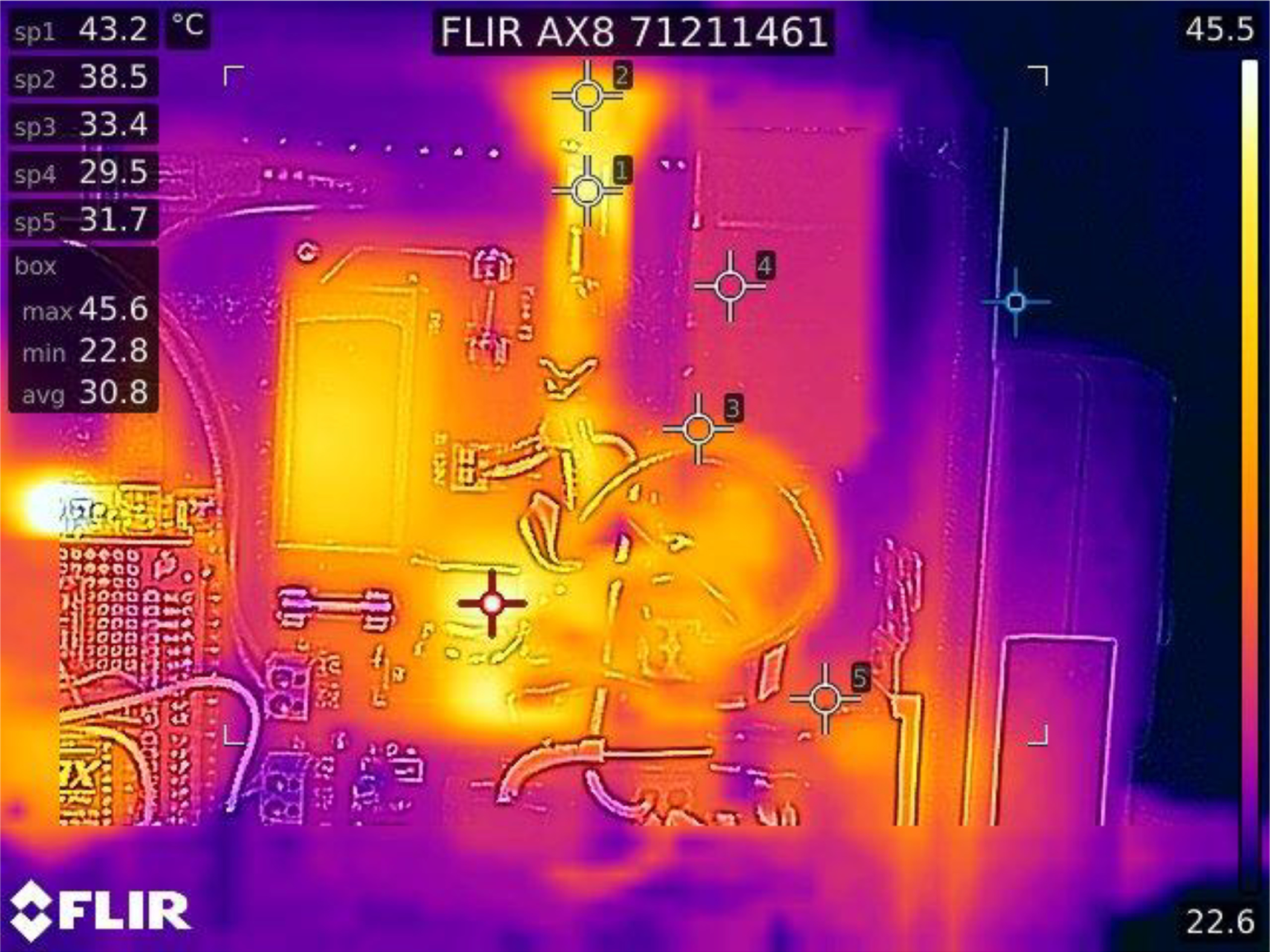
Thermal imaging test of a laser activity monitoring unit with a 4.5 A current load.
4. Discussion:
4.1. Logic Control Considerations
A flow diagram of the program logic for the laser activity monitor and indicator units is shown in Fig. 9. A broadcast loop for the monitor box repeats every 50 ms plus a random offset of up to 20 ms. Between each broadcast, the microcontroller checks whether current sensing mode or TTL sensing mode is active and performs calculations to determine laser activity based on the chosen mode. A two-digit integer is encoded to identify laser system and laser status in Fig. 9A. This integer is received and decoded by the activity indicator units, which synchronously updates all LED status lights on the box every 500 ms. At ten times the average monitor broadcast loop duration, 500 ms should be enough time to capture updates from multiple lasers even in the rare cases with high numbers of signal collisions. The indicator box also checks if any laser updates were delayed more than 3 s and, if so, puts the LED status lights in an error state with blinking lights.
Fig. 9:
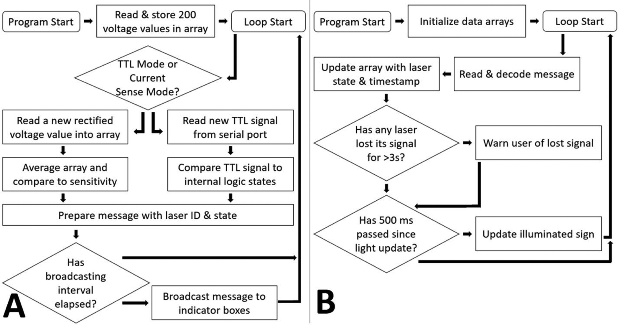
Logic control flow diagram of laser activity monitor (A) and indicator units (B).
4.2. Integration & Role of Remote Monitoring Units in a Research Lab
The network timing results demonstrate that a local network of up to 4 laser monitors with multiple indicator units can be installed in a laboratory without concern over data collisions, as only a small percentage of signals are lost and even longer delays become increasing unlikely. No signal delays larger than 350 ms were measured from a total of 62,932 readings, which is still short enough that the LED status lights should be able to update in time for an observer at the entrance to be alerted. The open source platform makes it easy to scale to larger numbers of lasers in a laboratory with minor code and hardware modifications, but users should be aware that data collisions will become more frequent with an increasing number of broadcast signals.
The thermal imaging measurements show that some elements of the activity monitor run at elevated temperatures during normal operation and that current should be limited to prevent softening of the thermoplastic housing material. The particular thermoplastic used for this open source design was compatible with the intended maximum operating current of 4.5 A, although new thermal testing would need to be performed if a future researcher decides to use a different type of thermoplastic material for their own 3D printed implementation of the case.
Furthermore, a future design that is better suited to higher currents could be built using similar circuitry but instead enclosed in a metal chassis. If the open source design were transferred to a metal chassis, machining would be required to form apertures for the required ports, but a higher operating current might be achieved as metal would increase heat transfer rates to the surrounding atmosphere while also serving as a large heat sink. If the intention of a metal chassis is to increase current levels, the fuse would also need to be replaced with a more suitable option, along with reviewing the current limits of any other wiring or components used. A small 12 VDC fan could even be incorporated into a high current metal enclosure to further reduce the temperature, in which case the leads from the fan could be easily connected to terminal blocks 3 and 4 in Fig. 2. The metal chassis would additionally provide for simple grounding that would be beneficial in a high current high voltage device, instead of relying on the electrical insulation of the plastic in the 3D printed version of the design. The 3D printed enclosure design was chosen over metal for the first design to provide a simple and cost-effective manufacturing solution that doesn’t require access to a machine shop or involve much machining labor to replicate. Although the maximum intended current of 4.5 A might not be suitable for all lasers, the TTL operational mode of the laser monitor provides for an alternative way to monitor high current laser systems without requiring modification to the underlying design in a 3D printed enclosure.
The open source nature of the design makes it easy for other research labs to customize the laser activity monitoring system to their needs, provided they are skilled in basic electronics. It is even recognized that the system could be expanded for performance based monitoring of the laser, given that the hardware is already in place for electrical current monitoring and a TTL port exists that could additionally read and process various types of inputs from the laser with some code modifications. Implementation of a real time operating system (RTOS), while not pursued with the current design, would be another future improvement that could be implemented using the existing Arduino or with another microcontroller. It is expected that the timing characteristics of both data acquisition and network transmission could be improved by implementing an RTOS or making better use of timer interrupts. Some additional features that could be easily added, but were not built into this base model, include an audible alert or a door interlock switch that automatically shuts off the laser power if the door is opened. A future hardware improvement that could make it more obvious when there is a communication error would be to build in a dedicated warning LED into the laser indicator unit, as opposed to the current system which flashes when there is a communication error on a particular laser. The current system is not meant to be used as the sole safety system in the laboratory and is instead designed with the goal of providing research laboratories with their own in-house electronics expertise the ability to quickly retrofit entrances with near real-time illuminated laser status that can be customized as needed. A quality assurance program and lab maintenance schedule with approval by the local laser safety authority must be performed by any laboratory that decides to build their own version of the laser monitoring system. In addition, the electrical requirements of the open source design would need to be reviewed by an institution seeking to implement the laser monitoring system, in particular for electrical grids globally that may be different than what is commonly seen in the United States.
5. Conclusion:
An open source laser activity monitoring system was built and tested for enabling research labs to implement their own custom laser monitoring systems that can incorporate multiple lasers from different manufacturers in laboratories with an arbitrary number of entrances. The as-built 3D printed platform allows for electrical current or TTL signal monitoring of most common laser systems and wirelessly updates illuminated activity indicators at entrances, while also providing an optional emergency stop button. The monitoring capabilities and program complexity can be customized to a wide variety of installed laser equipment. Any lab implementing this system would need to work with their own institution to approve the construction and testing of the laser monitoring system, as the open source nature is dependent on the skillset of the person assembling it. It is expected that the laser monitoring system would form a part of a more comprehensive laser safety protocol and would be at the discretion of the laser safety officer. Thermal imaging tests demonstrated acceptable temperatures within the plastic laser activity monitoring box while using the intended 4.5 A max operating current draw from the monitored laser. A network of four broadcasting laser monitor nodes and one receiving node was found to have an acceptable level of data collisions, with over 96% of signals being received without delay and the remaining signals being received within 350 ms at the extremum. Broadcasting laser nodes may be added to the existing open source laser monitoring system with minor hardware and enclosure design changes, e.g., for labs wanting to monitor more than four unique lasers, understanding that increasing laser nodes will increase signal collisions and may result in some data loss. The design files are being provided (https://morgridge.org/designs) for further experimentation by research labs requiring a wireless laser activity monitoring system that is broadly compatible with commercial lasers.
Highlights.
There is a need for flexible and cost-effective basic laser monitoring systems.
Goal is to alert users to active laser beams and ensure proper laser use.
Description of an open source 3D printed remote monitoring system.
Selectively monitors either the total laser current or shutter signal.
Can wirelessly indicate at the laboratory entrances that a laser is in use.
Acknowledgment:
This study was supported by the Morgridge Institute for Research and NIH grant# R01 CA185251 (KWE). We thank Mr. Alec Riddle, Dr. Bing Dai, Dr. Md Abdul Kader Sagar and Dr. Jenu Chacko for their assistance with installation, testing, and deployment.
Nomenclature:
- ABS
acrylonitrile butadiene styrene
- ADC
analog-to-digital converter
- ANSI
American National Standards Institute
- AC
alternating current
- CAD
computer aided design
- EMI
electromagnetic interference
- FDM
fused deposition modeling
- IDE
integrated development environment
- LED
light emitting diode
- PCB
printed circuit board
- RF
radiofrequency
- RTOS
real time operating system
- TTL
transistor-transistor logic
Footnotes
Publisher's Disclaimer: This is a PDF file of an unedited manuscript that has been accepted for publication. As a service to our customers we are providing this early version of the manuscript. The manuscript will undergo copyediting, typesetting, and review of the resulting proof before it is published in its final form. Please note that during the production process errors may be discovered which could affect the content, and all legal disclaimers that apply to the journal pertain.
Declaration of interests
The authors declare that they have no known competing financial interests or personal relationships that could have appeared to influence the work reported in this paper.
References:
- [1].Denk W, Strickler JH, & Webb WW (1990). Two-photon laser scanning fluorescence microscopy. Science, 248(4951), 73–76. DOI: 10.1126/science.2321027 [DOI] [PubMed] [Google Scholar]
- [2].Bidare P, Maier RRJ, Beck RJ, Shephard JD, & Moore AJ (2017). An open-architecture metal powder bed fusion system for in-situ process measurements. Additive Manufacturing, 16, 177–185. DOI: 10.1016/j.addma.2017.06.007 [DOI] [Google Scholar]
- [3].Laser Institute of America, American National Standards Institute. (2009). American national standard for safe use of lasers in educational institutions. Orlando, FL: Laser Institute of America. [Google Scholar]
- [4].American National Standards Institute. (2012). ANSI Z136.8–2012 American National Standard for safe use of lasers in research, development, or testing. Orlando, Florida: Laser Institute of America. [Google Scholar]
- [5].Sliney D (1995). Laser Safety. Lasers in Surgery and Medicine, 16(3), 215–225. DOI: 10.3828/sfftv.2012.16 [DOI] [PubMed] [Google Scholar]
- [6].Vasudevan L, Menchaca DI, & Tutt J (2015). Laser safety program development at Texas A & M University - Issues and challenges. Health Physics, 109(3), 205–211. DOI: 10.1097/HP.0000000000000328 [DOI] [PubMed] [Google Scholar]
- [7].Barkana Y, & Belkin M (2000). Laser eye injuries. Survey of Ophthalmology, 44(6), 459–478. DOI: 10.1016/S0039-6257(00)00112-0 [DOI] [PubMed] [Google Scholar]
- [8].Gershon K, Peterson G, & Barat K (1997). The Berkeley interlock for laser safety. International Laser Safety Conference, 1, 598–600. DOI: 10.2351/1.5056456 [DOI] [Google Scholar]
- [9].Bikas H, Stavropoulos P, & Chryssolouris G (2016). Additive manufacturing methods and modelling approaches: a critical review. The International Journal of Advanced Manufacturing Technology, 83(1–4), 389–405. DOI: 10.1007/s00170-015-7576-2. [DOI] [Google Scholar]
- [10].Teledyne FLIR. (2015, November 5). Use Low-Cost Materials to Increase Target Emissivity. Retrieved May 14, 2021, from https://www.flir.com/discover/rd-science/use-low-cost-materials-to-increase-target-emissivity/