Abstract
Conformal transformation optics is employed to enhance an H-plane horn’s directivity by designing a graded-index all-dielectric lens. The transformation is applied so that the phase error at the aperture is gradually eliminated inside the lens, leading to a low-profile high-gain lens antenna. The physical space shape is modified such that singular index values are avoided, and the optical path inside the lens is rescaled to eliminate superluminal regions. A prototype of the lens is fabricated using three-dimensional printing. The measurement results show that the realized gain of an H-plane horn antenna can be improved by 1.5–2.4 dB compared to a reference H-plane horn.
Subject terms: Electrical and electronic engineering, Transformation optics, Materials for devices
Introduction
Ever since transformation optics (TO) was proposed by Pendry1 and Leonhardt2 in 2006, it has been used in a plethora of applications, like carpet cloaking3–5, polarization splitting and transforming6–10, waveguide coupling11–17, lens compression18–21, lens flattening22–24, and directivity enhancement25–31. TO provides a systematic approach to finding a material that realizes a particular functionality, which is essentially an inverse problem. This method establishes a correspondence between the electromagnetic fields and media of two spaces: virtual and physical. The two spaces are geometrically related to each other by a mapping. Based on the form-invariance of Maxwell’s equations, TO implies that a calculated transformation medium can mimic space deformation.
The material derived by the general types of transformation is quite complex and may be difficult to realize. The transformation medium is, in many cases, nonhomogeneous, anisotropic, and possesses extreme permittivity and permeability values. Such media can be realized with the use of resonant metamaterials, which inevitably limit the bandwidth of operation. In contrast, all-dielectric graded-index materials (GRIN) are advantageous in terms of realization and can operate over a wide bandwidth. GRIN devices can perform a variety of functions, such as waveguide mode conversion32,33, waveguide splitting34, and cloaking within a waveguide35. Also, they can act as an acoustic retroreflector36 and can support Fano resonances inside a waveguide37. To enhance the practicality of TO designs and achieve a GRIN media, conformal TO (CTO) and quasi-conformal TO (QCTO) are employed. The transformation used in the case of CTO is analytical. Such property removes the anisotropy from the transformation medium and makes the material all-dielectric for 2D cases where the electric field polarization is out-of-plane.
Horn antennas are among the simplest and most common types of antennas. A metallic tapering is introduced to ensure proper impedance matching while providing high directivity. These antennas are used as reflector feeds, phased array elements, calibration antennas for measurements, etc. H-plane horns are low-profile since the tapering is applied only to the H-plane. Such a slim antenna can be used as an array element. There are methods to improve the radiation characteristics of a horn. For example, using corrugations, which is common in conical antennas, can help attain lower sidelobe, backlobe, and cross-polarization levels as well as a better radiation pattern symmetry. All these features are required when using a horn as a reflector feed, especially in satellite applications38. Also, using profiled boundaries can make the horn shorter and provide better phase center stability39. The directivity of the horn can be enhanced by using longitudinal strips and dielectric fillings (hard horn) or stepped tapers (multi-mode horn)40–42.
An effective way to enhance the directivity is to place a homogeneous dielectric lens at the antenna aperture. While such lenses reduce the phase error at the aperture, they make the antenna bulkier and introduce intrinsic reflections due to the impedance mismatch39. Using anti-reflection (AR) layers can reduce the reflections at the expense of limiting the bandwidth and increasing the fabrication complexity. However, in the case of GRIN lenses, the functionality depends more on the refractive index distribution of the lens rather than its shape. Using GRIN lenses, the mismatch can be mitigated by engineering the impedance, and also, the profile of the lens antenna can be smaller compared to conventional dielectric lenses. Using TO, one can design a graded-index lens that is conformal to the horn’s body. Hence, the lens is embedded in the horn, leading to a compact horn lens antenna.
Several works in the literature employ CTO and QCTO to enhance the directivity of antennas26–31. In these works, the transformation is applied to design a lens that mitigates the phase error at the device aperture. Using this approach, the rays arrive at the aperture in-phase and at perpendicular angles. However, there are three common shortcomings for applying CTO and QCTO to the case of lens antennas. First, the device’s refractive index lacks matching to free-space at the aperture since the cylindrical to plane wave conversion is realized in the TO design by mapping a curved phase front line to a straight one, which inherently leads to a non-unity refractive index. If the source is not embedded in the transformation regions and a lens cap is designed, reflections occur on both sides of the lens29. The reflection can be mitigated by using an AR coating. However, apart from making the structure frequency-dependent, the fabrication process is complex since the non-uniform refractive index at the aperture requires an AR coating with a non-uniform index and a non-uniform thickness43. Second, since the virtual space is stretched in some regions to fit the physical space shape, the refractive index falls below unity, meaning that some superluminal regions are created. Third, the refractive index can obtain singular values at the corners26–29. The superluminal regions and the extreme refractive index values at the corners are often neglected and substituted with an index of one27–30. However, this deteriorates the aperture efficiency since the new unity-index area does not contribute to the phase error compensation.
In this work, we address all of the above shortcomings to enhance the directivity of an H-plane horn antenna while keeping its refractive index at moderate, above-unity values. This is achieved by applying CTO in such a way that the refractive index at the aperture matches that of the environment, keeping reflections to a minimum while preventing extreme refractive index values at the corners. Besides, any superluminal regions are remedied by rescaling the optical path44. To prove the functionality of our design method, we fabricated a prototype of the lens using a 3D printer and evaluated its performance in the band. It is seen that the realized gain can be increased by 1.5-2.4 dB.
Design method
The 2D virtual and physical spaces are described by Cartesian coordinates (u,v) and (x,y), respectively. If we define the complex variables and , the analytical function Z(W) describes the conformal transformation from virtual to physical space. If the refractive index of the virtual space is n(u, v), then the refractive index of the physical space n(x, y) is derived using the well-known TO formula2:
| 1 |
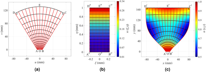
Figure 1 illustrates the mapping procedure for the design of a directive CTO horn antenna. The coordinates of virtual and physical spaces are assigned as (u, v) and (x, y). In order to map the virtual space to the physical space, a canonical intermediate mapping domain is chosen. The most common canonical shapes are a rectangle and a unity circle; we choose a rectangle as the canonical intermediate region, and denote its coordinates as . Based on the Riemann theory of conformal mapping, all quadrilaterals are conformally equivalent if and only if they share the same conformal module45. The conformal module of a rectangle is its aspect ratio.
Figure 1.
The schematics of (a) the virtual space, (b) the intermediate space and its refractive index, and (c) the physical space and its refractive index. The constant and coordinate lines in the intermediate space and their corresponding mapped images in the virtual and physical spaces are depicted by black and red lines, respectively.
The fully-employed CTO does not induce reflections in principle as it is derived directly by applying a coordinate transformation to the 2D Helmholtz equation. However, if a ‘finite embedded’ transformation is employed46 or the physical space domain is curtailed for practical purposes, an intrinsic boundary reflection is created47. This reflection is inherently induced, although it may be negligible depending on the design requirements. Part of the reason is that the transformation continuity required for the reflectionless property at the input and output boundaries of the device can not be fully satisfied due to the uniqueness theorem48 (Theorem 10.39). That is, if the transformation continuity is satisfied on the outer boundary of a transformed region, then the transformation should be a unity transformation everywhere, which is not the case with CTO designs. As we demonstrate in our design method, the boundary reflections can be reduced by carefully considering some factors.
Note that although the CTO is essentially defined for 2D cases, it is applicable to quasi-2D cases such as H-plane horn antennas. For the case of H-plane horn antennas, the guided mode excited by the feeding waveguide is the mode. This mode does not have vertical variations, i.e., it is uniform in the z-direction, complying with the 2D assumptions of the CTO. This is the main mode excited in the horn. Also, the wavefronts of the guided mode inside an empty horn’s body closely resemble cylindrical contours49. As a result, in our design method, the virtual space depicted in Fig. 1a is the body of a horn that is filled with a vacuum. The horn’s throat matches the WR62 waveguide with a length of 15.8 mm, and the flare angle equals 31 . The physical space depicted in Fig. 1c is a region similar to the virtual space with two significant differences. First, the cd edge is flattened into that eventually leads to the directivity enhancement. Second, the side boundaries are curves rather than straight lines. We have carefully defined and curves. The curve slope matches the flare angle near the throat and has zero first and second derivatives, and , at the aperture. The zero first derivative ensures that the aperture corner angles are 90 in all three spaces, which helps us avoid singular refractive index values near the corners. The zero second derivative increases the uniformity of the refractive index at the aperture. To avoid extreme refractive indices near the corners, the angles at the , , , and corners must equal the ones of , , , and , respectively. The throat’s width of the horn antenna in the physical space is similar to the virtual space’s one (=) to get the refractive index close to one. In the physical space, the aperture has a length of 167 mm, which corresponds to 8.35 free-space wavelengths at the frequency of 15 GHz. The lens antenna length equals 167 mm.
By solving a boundary-value problem, the physical space’s conformal module is calculated, and it equals 0.4444. Hence, the intermediate rectangle aspect ratio is known, and we choose a unit length for its longer side. The bc side’s length is tuned to mm to make the conformal module of the virtual space equal to 0.44. The conformal module equality in all three spaces guarantees the existence of the conformal map.
Knowing the dimensions of all three spaces, the mapping from the virtual space to the physical space is conducted by solving Laplace’s equation in the virtual and physical spaces separately for the intermediate space and coordinates and combining the results of the mapping. The intermediate region’s refractive index is calculated by establishing the conformal mapping between the virtual space and the intermediate space shown in Fig. 1b. Then, the physical space’s final refractive index is derived by calculating the conformal mapping between the intermediate space and the physical space. The refractive index formula follows:
| 2 |
where the denominator is the refractive index of the intermediate space. The refractive index of the physical space is depicted in Fig. 1c. It is seen that the refractive index is below unity in some areas. Having established the correspondence of all points in all three spaces, the constant and coordinate lines in the intermediate space and their corresponding mapped lines in the virtual and physical spaces are illustrated in Fig. 1 by black and red lines, respectively.
The only remaining issue is the superluminal area, which can be mitigated by the following optical path rescaling method44. Consider one of the rays in Fig. 1c (that are shown in red). We can define an optical path associated with any point A lying on that ray as an integral
| 3 |
Here, the integral is taken along the ray from point A to point A. A is a point on the ray for which the optical path is set to zero. In our case, A is the intersection of the ray with the line where we define the optical path to be zero. The optical path defined in this way is proportional to the phase of the wave associated with the rays; the proportionality factor is . Since each point of the physical space lies on exactly one ray (according to our design of the rays in Fig. 1c), we can define the optical path S(x, y) in the whole physical space. The refractive index then satisfies , and the direction of is tangent to the ray passing through the given point.
Now, suppose we define an increasing function that we call the “rescaled optical path”. If we imagine that rather than S describes the optical path, then the corresponding refractive index will be
| 4 |
Note that the refractive index has changed while the shape of the rays has not. This shows that there can be different index profiles corresponding to the same set of rays. We can now employ this freedom to manipulate the index according to our needs. In particular, we will use it to eliminate the superluminal region in Fig. 1c. Since the index n has the lowest values along the curve (or equivalently, along ), we require the index to be unity along these curves. Therefore, the rescaled optical path along the ray must equal the length measured along that ray. This, combined with the known original optical path S along that ray, fully defines the rescaling , which is shown in Fig. 2 for our case.
Figure 2.
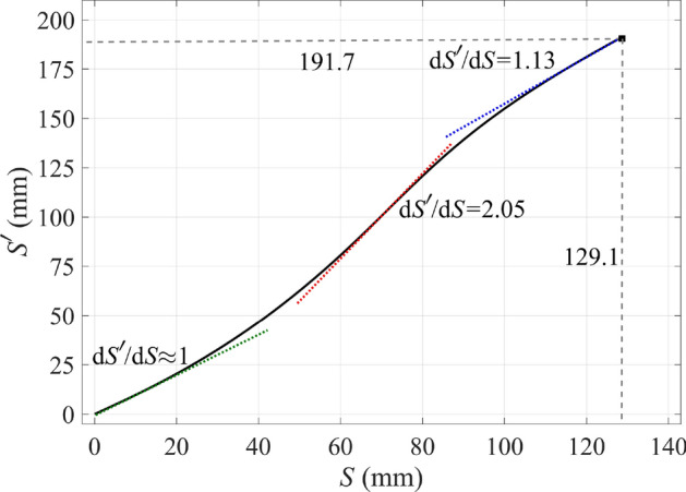
The rescaled optical path function . The maximum value of is 192 mm, which equals the length of the ray in Fig. 1c. Also the maximum value of S is 129 mm that equals the length of the straight ray bc in Fig. 1a as required.
When we apply the rescaling function to the whole physical space, we get the refractive index shown in Fig. 3. We see that the superluminal regions have disappeared completely, which was our goal, and the entire refractive index profile ranges from unity to about 1.44.
Figure 3.
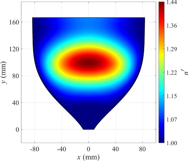
Refractive index of the CTO horn antenna after rescaling the optical path for mitigating the superluminal regions.
Horn lens antenna implementation
To validate the proposed method, an H-plane horn lens antenna operating at 15 GHz is designed and manufactured. It is terminated with an E-plane flare to suppress reflections at the aperture of the antenna occurring due to the aperture mismatch. In addition, an H-plane horn antenna is designed and manufactured and serves as a reference. The reference antenna has a slight linear E-plane taper (from the feeding to the aperture) so that the aperture is the same as for the horn lens antenna. The two antennas are illustrated in Fig. 4.
Figure 4.
Rendition of (a) the H-plane horn lens antenna, and (b) the reference H-plane horn antenna.
The two metallic structures are manufactured in two parts each, and the two parts are joined together with screws. A glide-symmetric holey EBG structure is placed along the sidewalls of the structures to avoid leakage50,51. The two antennas are fed by a standard WR62 (15.79 mm width and 7.9 mm height) rectangular waveguide. The manufactured prototypes are presented in Fig. 5.
Figure 5.
Photograph of (a) the H-plane horn lens prototype, and (b) the reference H-plane horn prototype.
The phase-correcting lens (highlighted in grey in Fig. 4a) consists of a dielectric slab with periodically spaced square holes. The side of the holes is varied throughout the slab to create the required gradient index profile (Fig. 3). Each hole experiences a quasi-periodic environment. Therefore, the effect of the hole size on the equivalent refractive index can be studied with the eigenmode solver of CST with periodic boundary conditions. The equivalent refractive index was calculated as the relation between the propagation constant in the periodic structure and the propagation constant in free space52,53. The equivalent refractive index versus the frequency is presented in Fig. 6 for various hole size values. Since the maximum required refractive index in the lens is 1.44, a permittivity of 3 is chosen for the dielectric slab. It should be noted that, since a desktop 3D printer is used for manufacturing, the lowest reachable equivalent refractive index is above unity54. This results in slightly increased reflections at the borders of the lens.
Figure 6.
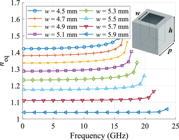
Equivalent refractive index of the perforated dielectric slab () for various hole sizes ( mm and mm).
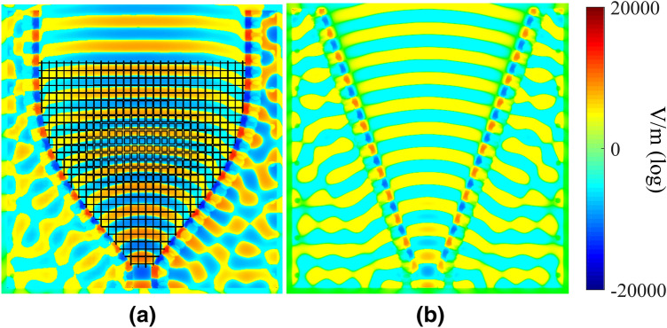
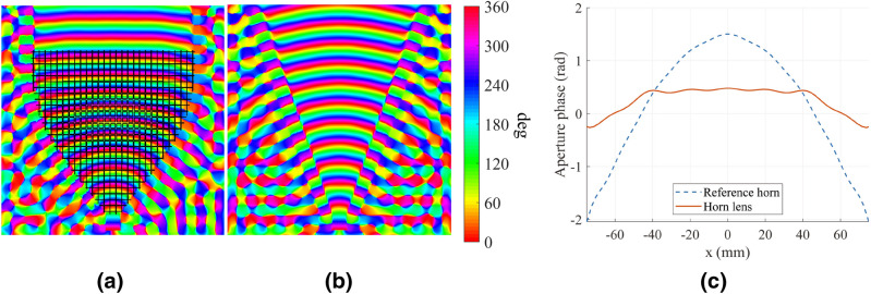
The two structures in Fig. 4 are simulated using the time domain solver of CST, and the E-field amplitude and phase are shown in Figs. 7 and 8. Boundary conditions were assumed to be ‘open add space’ in CST, which means radiating boundary conditions. The structure was excited with a ‘waveguide port’ including only one mode, the , which is the only one above cut-off at this specific frequency. Furthermore, the simulated phase distribution of the electric field at the border of the aperture of both antennas is presented in Fig. 8. It is seen that the lens flattens the phase front at the aperture.
Figure 7.
Simulated amplitude distribution of for the two H-plane antennas: (a) horn lens, and (b) reference horn. The dimensions are mm, mm, mm, and mm.
Figure 8.
Simulated phase distribution of for the two H-plane antennas: (a) horn lens, and (b) reference horn. (c) Aperture phase comparison between the H-plane horn lens (solid red line) and reference horn (dashed blue line). The dimensions are mm, mm, mm, and mm.
The simulated and measured reflection coefficients are depicted in Fig. 9. Low reflections ( dB) are observed in a wide bandwidth for both antennas. The differences in the measured reflection coefficient are due to the tolerances in the lens manufacturing, which was done in-house using a standard desktop 3D printer. In terms of bandwidth, this device is limited by the implementation aspects. More specifically, the lowest frequency of operation is limited by the cut-off frequency of the mode in the band. The standard establishes the minimum frequency in the band at 12 GHz. The highest frequency is constrained by the operation of the dielectric unit cell (illustrated in Fig. 6) and the quality of the coax-to-waveguide transition (illustrated in Fig. 9). Both aspects are limited to approximately 16 GHz.
Figure 9.
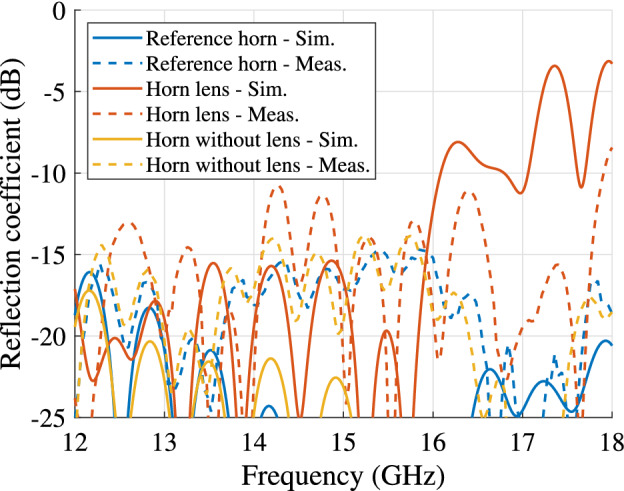
Simulated and measured reflection coefficients for the horn lens antenna, profiled horn antenna without lens, and the reference antenna. The dimensions are mm, mm, mm, and .
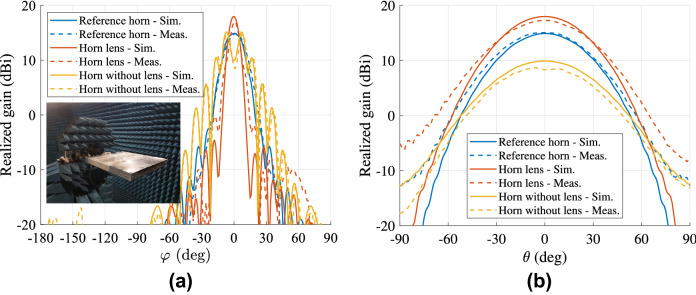
The simulated and measured far-field (two cuts) at 15 GHz are presented in Fig. 10. The gain versus the frequency for the two antennas is illustrated in Fig. 11. The horn lens antenna has a higher peak gain than the reference horn antenna over a wide bandwidth (1.5-2.4 dB higher measured gain in the frequency range 12-16 GHz). This gain enhancement corresponds to an increase of the effective aperture area by a factor of 1.3-1.7. A comparison is also made between the horn lens and the profiled horn without the lens embedded. The comparison is presented in Figs. 9, 10 and 11.
Figure 10.
Simulated and measured far-field of (a) H-plane (), and (b) E-plane () at 15 GHz for the horn lens antenna, profiled horn antenna without lens, and the reference antenna. The dimensions are mm, mm, mm, and mm.
Figure 11.
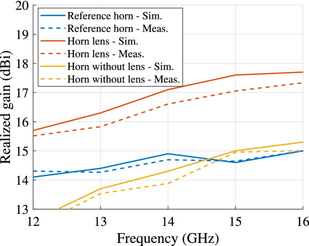
Simulated and measured realized gain for the horn lens antenna, profiled horn antenna without lens, and the reference horn antenna. The dimensions are mm, mm, mm, and mm.
Conclusion
In this work, we demonstrated a design methodology for a GRIN lens that corrects the phase error in the aperture of a conventional horn antenna. Our design considerations avoid the singular index values and employ an optical path rescaling to mitigate the need for a sub-unity refractive index. Here, we focused on enhancing the directivity of a horn antenna by designing a conformal lens. However, our methodology can be used to design various GRIN elements, including beam compressors and expanders, waveguide couplers, and plasmonic cloaks.
Author contributions
H.E., T.T., and O.Q.T. conceived the general idea. H.E. calculated the mapping. J.L.A.L. and O.Z. implemented, simulated, fabricated, and measured the antennas. H.E. wrote the first version of the manuscript. O.Q.T. and T.T. supervised the research. All authors discussed the content, reviewed and edited the manuscript.
Competing Interests
The authors declare no competing interests.
Footnotes
Publisher's note
Springer Nature remains neutral with regard to jurisdictional claims in published maps and institutional affiliations.
References
- 1.Pendry JB. Controlling electromagnetic fields. Science. 2006;312:1780–1782. doi: 10.1126/science.1125907. [DOI] [PubMed] [Google Scholar]
- 2.Leonhardt U. Optical conformal mapping. Science. 2006;312:1777–1780. doi: 10.1126/science.1126493. [DOI] [PubMed] [Google Scholar]
- 3.Li J, Pendry JB. Hiding under the carpet: A new strategy for cloaking. Physical Review Letters. 2008;101:203901. doi: 10.1103/physrevlett.101.203901. [DOI] [PubMed] [Google Scholar]
- 4.Chang Z, Zhou X, Hu J, Hu G. Design method for quasi-isotropic transformation materials based on inverse Laplace’s equation with sliding boundaries. Optics Express. 2010;18:6089–6096. doi: 10.1364/oe.18.006089. [DOI] [PubMed] [Google Scholar]
- 5.Ma HF, Cui TJ. Three-dimensional broadband ground-plane cloak made of metamaterials. Nature Communications. 2010;1:21. doi: 10.1038/ncomms1023. [DOI] [PMC free article] [PubMed] [Google Scholar]
- 6.Kwon D-H, Werner DH. Polarization splitter and polarization rotator designs based on transformation optics. Optics Express. 2008;16:18731–18738. doi: 10.1364/oe.16.018731. [DOI] [PubMed] [Google Scholar]
- 7.Eskandari H, Majedi MS, Attari AR. Design of reflectionless non-magnetic homogeneous polarization splitters with minimum anisotropy based on transformation electromagnetics. Journal of the Optical Society of America B. 2017;34:1191–1198. doi: 10.1364/josab.34.001191. [DOI] [Google Scholar]
- 8.Mousavi SSS, Majedi MS, Eskandari H. Design and simulation of polarization transformers using transformation electromagnetics. Optik. 2017;130:1099–1106. doi: 10.1016/j.ijleo.2016.11.129. [DOI] [Google Scholar]
- 9.Eskandari H, Majedi MS, Attari AR. Non-reflecting non-magnetic homogeneous polarization splitter and polarization deflector design based on transformation electromagnetics. Optik. 2017;135:407–416. doi: 10.1016/j.ijleo.2017.01.080. [DOI] [Google Scholar]
- 10.Eskandari H, Attari AR, Majedi MS. Design of polarization splitting devices with ideal transmission and anisotropy considerations. Journal of the Optical Society of America B. 2018;35:1585–1595. doi: 10.1364/josab.35.001585. [DOI] [Google Scholar]
- 11.Landy NI, Padilla WJ. Guiding light with conformal transformations. Optics Express. 2009;17:14872–14879. doi: 10.1364/oe.17.014872. [DOI] [PubMed] [Google Scholar]
- 12.García-Meca C, et al. Squeezing and expanding light without reflections via transformation optics. Optics Express. 2011;19:3562–3575. doi: 10.1364/oe.19.003562. [DOI] [PubMed] [Google Scholar]
- 13.Eskandari H, Majedi MS, Attari AR. Reflectionless compact nonmagnetic optical waveguide coupler design based on transformation optics. Applied Optics. 2017;56:5599–5606. doi: 10.1364/ao.56.005599. [DOI] [PubMed] [Google Scholar]
- 14.Eskandari H, Attari AR, Majedi MS. Reflectionless design of a nonmagnetic homogeneous optical waveguide coupler based on transformation optics. Journal of the Optical Society of America B. 2017;35:54–60. doi: 10.1364/josab.35.000054. [DOI] [PubMed] [Google Scholar]
- 15.Eskandari H, Quevedo-Teruel O, Attari AR, Majedi MS. Transformation optics for perfect two-dimensional non-magnetic all-mode waveguide couplers. Optical Materials Express. 2019;9:1320–1332. doi: 10.1364/ome.9.001320. [DOI] [Google Scholar]
- 16.Eskandari, H., Quevedo-Teruel, O., Attari, A. R. & Majedi, M. S. Design of nonmagnetic all-mode waveguide coupler with perfect transmission using transformation optics. In 2019 13th European Conference on Antennas and Propagation (EuCAP), 1–4 (2019).
- 17.Eskandari, H., Attari, A. R., Majedi, M. S. & Tyc, T. Waveguide tapering using conformal transformation optics for ideal transmission. In 2019 Thirteenth International Congress on Artificial Materials for Novel Wave Phenomena (Metamaterials), X–116–X–118. 10.1109/MetaMaterials.2019.8900947 (2019).
- 18.Quevedo-Teruel, O. et al. Transformation optics for antennas: why limit the bandwidth with metamaterials?. Sci. Rep.3, 10.1038/srep01903 (2013). [DOI] [PMC free article] [PubMed]
- 19.Eskandari H, Majedi MS, Attari AR, Quevedo-Teruel O. Elliptical generalized Maxwell fish-eye lens using conformal mapping. New Journal of Physics. 2019;21:063010. doi: 10.1088/1367-2630/ab2471. [DOI] [Google Scholar]
- 20.Ebrahimpouri M, Quevedo-Teruel O. Ultrawideband anisotropic glide-symmetric metasurfaces. IEEE Antennas and Wireless Propagation Letters. 2019;18:1547–1551. doi: 10.1109/lawp.2019.2922238. [DOI] [Google Scholar]
- 21.Chen Q, Giusti F, Valerio G, Mesa F, Quevedo-Teruel O. Anisotropic glide-symmetric substrate-integrated-holey metasurface for a compressed ultrawideband Luneburg lens. Applied Physics Letters. 2021;118:084102. doi: 10.1063/5.0041586. [DOI] [Google Scholar]
- 22.Hunt J, et al. Planar, flattened luneburg lens at infrared wavelengths. Optics Express. 2012;20:1706–1713. doi: 10.1364/oe.20.001706. [DOI] [PubMed] [Google Scholar]
- 23.Driscoll T, et al. Performance of a three dimensional transformation-optical-flattened lüneburg lens. Optics Express. 2012;20:13262–13273. doi: 10.1364/oe.20.013262. [DOI] [PubMed] [Google Scholar]
- 24.Zhou F, et al. Additive manufacturing of a 3D terahertz gradient-refractive index lens. Advanced Optical Materials. 2016;4:1034–1040. doi: 10.1002/adom.201600033. [DOI] [Google Scholar]
- 25.Yao K, Jiang X. Designing feasible optical devices via conformal mapping. Journal of the Optical Society of America B. 2011;28:1037–1042. doi: 10.1364/josab.28.001037. [DOI] [Google Scholar]
- 26.Schmiele M, Varma VS, Rockstuhl C, Lederer F. Designing optical elements from isotropic materials by using transformation optics. Physical Review A. 2010;81:033837. doi: 10.1103/physreva.81.033837. [DOI] [Google Scholar]
- 27.Aghanejad I, Abiri H, Yahaghi A. Design of high-gain lens antenna by gradient-index metamaterials using transformation optics. IEEE Transactions on Antennas and Propagation. 2012;60:4074–4081. doi: 10.1109/tap.2012.2207051. [DOI] [Google Scholar]
- 28.Ebrahimpouri M, Quevedo-Teruel O. Bespoke lenses based on quasi-conformal transformation optics technique. IEEE Transactions on Antennas and Propagation. 2017;65:2256–2264. doi: 10.1109/tap.2017.2679494. [DOI] [Google Scholar]
- 29.Ding T, Yi J, Li H, Zhang H, Burokur SN. 3D field-shaping lens using all-dielectric gradient refractive index materials. Scientific Reports. 2017;7:782. doi: 10.1038/s41598-017-00681-z. [DOI] [PMC free article] [PubMed] [Google Scholar]
- 30.Ebrahimpouri M, Zetterstrom O, Quevedo-Teruel O. Experimental validation of a bespoke lens for a slot log-spiral feed. IEEE Antennas and Wireless Propagation Letters. 2020;19:557–560. doi: 10.1109/LAWP.2020.2971852. [DOI] [Google Scholar]
- 31.Eskandari, H., Saviz, S. & Tyc, T. Directivity enhancement of a cylindrical wire antenna by a graded index dielectric shell designed using strictly conformal transformation optics. Sci. Rep.11, 10.1038/s41598-021-92200-4 (2021). [DOI] [PMC free article] [PubMed]
- 32.Xu, Y., Fu, Y. & Chen, H. Planar gradient metamaterials. Nat. Rev. Mater. 1, 10.1038/natrevmats.2016.67 (2016).
- 33.Wang, H., Xu, Y., Genevet, P., Jiang, J.-H. & Chen, H. Broadband mode conversion via gradient index metamaterials. Sci. Rep.6, 10.1038/srep24529 (2016). [DOI] [PMC free article] [PubMed]
- 34.Fu, Y., Xu, Y. & Chen, H. Applications of gradient index metamaterials in waveguides. Sci. Rep.5, 10.1038/srep18223 (2015). [DOI] [PMC free article] [PubMed]
- 35.Gu, C. et al. A broadband polarization-insensitive cloak based on mode conversion. Sci. Rep.5, 10.1038/srep12106 (2015). [DOI] [PMC free article] [PubMed]
- 36.Fu Y, et al. Compact acoustic retroreflector based on a mirrored luneburg lens. Physical Review Materials. 2018;2:105202. doi: 10.1103/physrevmaterials.2.105202. [DOI] [Google Scholar]
- 37.Xu, Y., Li, S., Hou, B. & Chen, H. Fano resonances from gradient-index metamaterials. Sci. Rep.6, 10.1038/srep19927 (2016). [DOI] [PMC free article] [PubMed]
- 38.Clarricoats, P. J. B. & Olver, A. D. Corrugated Horns for Microwave Antennas. (IET, 1984).
- 39.Olver, A. D., Clarricoats, P., Shafai, L. & Kishk, A. Microwave Horns and Feeds. (IET, 1994).
- 40.Lier E. Hard waveguide feeds with circular symmetry for aperture efficiency enhancement. Electronics Letters. 1988;24:166–167. doi: 10.1049/el:19880110. [DOI] [Google Scholar]
- 41.Bhattacharyya A, Goyette G. Step-horn antenna with high aperture efficiency and low cross-polarisation. Electronics Letters. 2002;38:1495–1496. doi: 10.1049/el:20021081. [DOI] [Google Scholar]
- 42.Lier, E. & Matthews, J. Performance comparison of high-gain horn antennas. In 2005 IEEE Antennas and Propagation Society International Symposium, 3, 753–756. 10.1109/aps.2005.1552365 (IEEE, 2005).
- 43.Morgan KL, Brocker DE, Campbell SD, Werner DH, Werner PL. Transformation-optics-inspired anti-reflective coating design for gradient index lenses. Optics Letters. 2015;40:2521–2524. doi: 10.1364/ol.40.002521. [DOI] [PubMed] [Google Scholar]
- 44.Eskandari, H. & Tyc, T. Controlling refractive index of transformation-optics devices via optical path rescaling. Sci. Rep.9, 10.1038/s41598-019-54516-0 (2019). [DOI] [PMC free article] [PubMed]
- 45.Papamichael, N. & Stylianopoulos, N. Numerical Conformal Mapping: Domain Decomposition and the Mapping of Quadrilaterals, chap. 2, 51–63 (World Scientific Pub Co Inc, 2010).
- 46.Rahm M, Cummer SA, Schurig D, Pendry JB, Smith DR. Optical design of reflectionless complex media by finite embedded coordinate transformations. Physical Review Letters. 2008;100:063903. doi: 10.1103/physrevlett.100.063903. [DOI] [PubMed] [Google Scholar]
- 47.Urzhumov YA, Kundtz NB, Smith DR, Pendry JB. Cross-section comparisons of cloaks designed by transformation optical and optical conformal mapping approaches. Journal of Optics. 2010;13:0242002. doi: 10.1088/2040-8978/13/2/024002. [DOI] [Google Scholar]
- 48.Shilov, G. E., Silverman, R. A. et al.Elementary Real and Complex Analysis (Courier Corporation, 1996).
- 49.Balanis, C. A. Antenna Theory: Analysis and Design (Wiley, 2016).
- 50.Ebrahimpouri M, Rajo-Iglesias E, Sipus Z, Quevedo-Teruel O. Cost-effective gap waveguide technology based on glide-symmetric holey EBG structures. IEEE Transactions on Microwave Theory and Techniques. 2018;66:927–934. doi: 10.1109/tmtt.2017.2764091. [DOI] [Google Scholar]
- 51.Ebrahimpouri, M., Algaba Brazalez, A., Manholm, L. & Quevedo-Teruel, O. Using glide-symmetric holes to reduce leakage between waveguide flanges. IEEE Microw. Wirel. Components Lett.28, 473–475. 10.1109/LMWC.2018.2824563 (2018).
- 52.Quevedo-Teruel O, et al. Glide-symmetric fully metallic luneburg lens for 5g communications at ka-band. IEEE Antennas and Wireless Propagation Letters. 2018;17:1588–1592. doi: 10.1109/LAWP.2018.2856371. [DOI] [Google Scholar]
- 53.Zetterstrom O, Hamarneh R, Quevedo-Teruel O. Experimental validation of a metasurface luneburg lens antenna implemented with glide-symmetric substrate-integrated holes. IEEE Antennas and Wireless Propagation Letters. 2021;20:698–702. doi: 10.1109/lawp.2021.3060283. [DOI] [Google Scholar]
- 54.Bjorkqvist O, Zetterstrom O, Quevedo-Teruel O. Additive manufactured dielectric gutman lens. Electronics Letters. 2019;55:1318–1320. doi: 10.1049/el.2019.2483. [DOI] [Google Scholar]


