Abstract
Objective This study was aimed to provide a key update to the seminal works of Prof. Albert L. Rhoton Jr., MD, with particular attention to previously unpublished insights from the oral tradition of his fellows, recent technological advances including endoscopy, and high-dynamic range (HDR) photodocumentation, and, local improvements in technique, we have developed to optimize efficient neuroanatomic study.
Methods Two formaldehyde-fixed cadaveric heads were injected with colored latex to demonstrate step-by-step specimen preparation for microscopic or endoscopic dissection. One formaldehyde-fixed brain was utilized to demonstrate optimal three-dimensional (3D) photodocumentation techniques.
Results Key steps of specimen preparation include vessel cannulation and securing, serial tap water flushing, specimen drainage, vessel injection with optimized and color-augmented latex material, and storage in 70% ethanol. Optimizations for photodocumentation included the incorporation of dry black drop cloth and covering materials, an imaging-oriented approach to specimen positioning and illumination, and single-camera stereoscopic capture techniques, emphasizing the three-exposure-times-per-eye approach to generating images for HDR postprocessing. Recommended tools, materials, and technical nuances were emphasized throughout. Relative advantages and limitations of major 3D projection systems were comparatively assessed, with sensitivity to audience size and purpose specific recommendations.
Conclusion We describe the first consolidated step-by-step approach to advanced neuroanatomy, including specimen preparation, dissection, and 3D photodocumentation, supplemented by previously unpublished insights from the Rhoton fellowship experience and lessons learned in our laboratories in the past years such that Prof. Rhoton's model can be realized, reproduced, and expanded upon in surgical neuroanatomy laboratories worldwide.
Keywords: skull base, endoscopy, imaging, three-dimensional photography, dissection, anatomy, neuroanatomy, education
Introduction
Anatomic study is a core pillar of surgical education and practice, promoting the knowledge and understanding that are necessary for all surgeons to perform procedures that are, to paraphrase Prof. Albert L. Rhoton Jr. MD, “accurate, gentle, and safe.” Although anatomy is a long-standing component of surgical residency curricula, the role of focused, high-complexity anatomic education is more important than ever before, given the changes in duty hours, litigation practices, and administrative burdens to which learners are subject.
Within modern neurosurgery, Prof. Rhoton was one of the first and most important proponents of formal neuroanatomic study, and the exquisitely detailed dissections produced under his direction and documented in professional quality images and descriptions remain unsurpassed in their novelty, accuracy, and educational value. 1 2 3 4 5 6 7 8 Although Prof. Rhoton and his colleagues put forth several manuscripts detailing the key aspects of specimen preparation, dissection, and three-dimensional (3D) photodocumentation, the available technology has advanced rapidly in the years since publication, and several preferred techniques evolved and were perfected as the laboratory's experience continued to grow. 9 10 11 12
Additionally, given the oral tradition of fellows passing innumerable subtleties and hard-earned lessons between generations, numerous techniques, and tips remained undocumented at the time of his death, resulting in a vanishing resource—particularly given that fewer than 120 fellows were directly trained under Prof. Rhoton at the University of Florida. 13 14 Correspondingly, the goal of the present study was to provide a critical update to these techniques, with particular attention to technological advances, previously unpublished procedural details, novel, and improved techniques learned in our laboratories, endoscopic dissection and photodocumentation, and postprocessing procedures.
Methods
Two formaldehyde-fixed anatomical specimens and one brain were utilized to illustrate the steps followed for preparation, vascular injection, dissection techniques, and 3D photodocumentation technique. A detailed step-by-step description and illustration was utilized to explain the techniques. The specimens were received after a standard process of embalming techniques using formaldehyde. The original embalming procedure utilized at University of Florida is described in Table 1 . Embalmed heads were isolated at the midcervical level via axial-plane transection. Prior to vessel preparation, specimens were immersed in 70% ethanol for ≥3 days, for optimal tissue fixation. This research was exempted from institutional review board in our institution, as it included anonymized cadaveric specimens.
Table 1. Embalming procedure performed at University of Florida for Prof. Rhoton's Laboratory.
| Steps | Description |
|---|---|
| 1 | Section and cannulation of the carotid artery (its superior part clamped) |
| 2 | Two perfusions toward the feet with 2 L of 37% formaldehyde + 10 L of water. The jugular vein should be divided and left open to drain the solution a |
| 3 | One perfusion with 3 L of solution A (40% phenol, 40% alcohol, 17% formaldehyde at 37%, 3% maquat 50—antifungal) + 9 L of water + 200 mL of glycerin a |
| 4 | Separate the specimen (head) from the body. |
| 5 | Perfusion through both carotid arteries (one at time), with 1 L of solution A + 11 L of water. Vertebral arteries and the contralateral carotid artery can be clamped once the solution leaks through these arteries |
| 6 | Store the specimen in buckets with ethanol 70% solution for at least 3 days to further fixate the tissues. |
If more brain tissue fixation is required, part of the solution of steps 2 and 3 can be directed through the carotid toward the head.
Results
Step-by-Step Specimen Preparation
Vessel Cannulation
Bilateral vertebral arteries (VA), common carotid arteries (CCA), and internal jugular veins (IJV) need to be carefully dissected from the cervical soft tissue and cannulated with the caliber-matched steel cannulas ( Fig. 1 ; Supplement 1A , B : available online only). Cannulas are secured with circumferentially tied 3–0 silk sutures, and reinforced by three-hole arterial fixation forceps (CCA/JV) or hemostats (VA) as required.
Fig. 1.
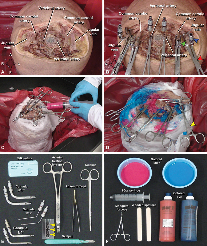
Cannulation, flushing and latex injection of the specimen. ( A ) Vessels isolated before cannulation (vertebral and carotid arteries, internal jugular veins). ( B ) The same vessels with stainless-steel cannulas (blue arrowhead), supported by a suture (green arrowhead), and an arterial fixation forceps (red arrowhead) for latex perfusion ( C ). ( D ) Final view after injection. To avoid overflowing of latex during perfusion, mosquito forceps (yellow arrowhead) were used to clamp the leaking soft tissue neck vessels and the perfused vessels. ( E, F ) Materials necessary for cannulation, flushing ( E ) and latex perfusion ( F ) of the specimen. Note the arterial fixation forceps with three holes (yellow arrowheads) to hold the cannulas. A, anterior; P, posterior; L, left; R, right.
Vessel Flushing
Vascular flushing with tap water eliminates residual intravascular blood products. Specimens are positioned inverted within a laboratory sink, and the secured cannulas are serially accessed with 60 cc Luer Lock syringes and flushed with 500 mL of water each, a procedure that repeated thrice daily for 3 days. Specimens may be maintained in the sink and covered with wet towels between daytime flushes but should be returned to 70% ethanol overnight. If more than minimal extravasation of fluid is noted from small head-and-neck vessels, usually muscular branches of the external carotid artery (ECA) or VA, they should be occluded with a small hemostat or suture ligation. Successful flushing is indicated by clear return of clot-free fluid by the end of day 3.
Latex Injection
Optimal latex perfusion requires maximal drainage of residual fluid from the vessels; correspondingly, specimens are stored upright in an empty bucket for 24 hours between final flushing and injection of the water-soluble latex. During injection, careful covering of the specimen skin and working sink reduces inadvertent staining. Colored latex mixtures are prepared in small containers—red for arteries and blue for veins—which may require the addition of supplemental commercial dye for deepened color, depending on the manufacturer ( Fig. 1 ; Supplement 1C : available online only). Any admixture should be slowly performed to minimize introduction of air bubbles. Following latex preparation, manual injection is performed using 60 cc syringes, first CCAs, then VAs, and finally IJVs, which typically require injections of 40, 20, and 100 mL per vessel, respectively.
Injection is performed under constant, mild-to-moderate pressure, with care taken to rapidly clean any latex leakage from the musculature, soft tissue, cervical epidural space, or small cervical vessels, the latter of which should be further controlled by application of hemostat clamps. Injection begins at the right CCA with all other cannulas open, and proceeds until egress of red latex is visualized at the contralateral CCA; If egress is noted first at either VA cannula, then the left CCA is occluded with an empty syringe and more latex is injected. The right CCA is left occluded, and the process is then repeated for the left CCA as the small distal vessels will still need additional amount of latex. This is followed by the bilateral VAs with the same technique, until adequate pressure and volume are achieved on all injections. Blue latex is then loaded into fresh syringes, and the process is repeated at the IJVs, after which the specimen is carefully decannulated and the vessels occluded with hemostats. Following definitive injection, the specimen is returned to an empty bucket placed in an inverted position and covered with wet towels where a 48-hour waiting period is required for the latex to fully set. Solidified latex is rubber-firm and does not stain when touched; if there is concern for incomplete setting, another 24 to 48 hours waiting period is appropriate, after which the specimen should be stored immersed in 70% ethanol whenever not under active dissection.
Dissection
Staging and Instrumentation
Specimens are optimally dissected on a well-illuminated surface, in an ergonomically favorable position. To prevent specimen desiccation, inactive regions should be covered with wet towels, while the dissection site should be periodically moistened using spray bottles of 70% ethanol. Both microdissection and endoscopic dissection benefit greatly from a full complement of surgical instruments specific to both approaches, including appropriate illumination and magnification sources, high-speed irrigating hand drills with numerous burrs, dissectors, punches, scissors, and a selection of clamps ( Supplement 1A : available online only).
3D Photodocumentation
Technical Overview
Video 1 This video demonstrates how to take 3D and HDR pictures of an anatomical specimen.
Following dissection and prior to photography, the specimen and staging are meticulously cleaned, and a dry, clean, black drop cloth is positioned under the specimen. Optimal positioning for photography depends solely on the framing and lighting considerations and should not be restricted by operative conventions. Specimen regions outside of the region of interest should be covered with black fabric that can be tacked in place, and the tissue should be periodically moistened with 70% ethanol in a spray bottle, sufficient to maintain a “glistening” appearance, but without causing reflection or large droplet formation.
The camera, ring flash, and sliding plate are assembled and positioned with the tripod legs extended and aligned evenly. The camera is positioned completely parallel to the floor in the horizontal plane, such that the sliding plate can be easily used without altering the camera's angulation and stability, or inadvertently contacting the tissue or instrumentation ( Fig. 2 ; Supplement 1D : available online only). It is crucial to ensure that the camera is completely horizontal, and there is no vertical displacement between the right and left images. By convention, the first image is captured with the camera positioned on the far-right edge of the sliding plate (e.g., the “right-eye” view); care should be taken to center of the image on a readily identifiable landmark, as high-quality 3D images depend on perfect alignment of the center point. Once the right image is acquired, the sliding plate is used to move the camera leftward, until the focal point previously in the center is now at the right edge of the viewfinder or before that point; the camera is then rotated to bring the focus back to the center of the viewfinder, and the “left-eye” image is captured ( Fig. 3 , Video 1 : available online only).
Fig. 2.
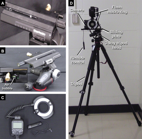
Equipment for 3D documentation in pictures taken with the photographic camera and a 100 mm macro lenses. ( A ) Anterior view of the sliding plate totally directed to the right side indicating the position required to take the first picture (right eye view). ( B ) Three-way tripod head presenting different knobs ( 1 , 2, and 3 ) to position the camera in different angles before the 3D documentation. Note the air bubble in the middle which indicates that the camera is horizontal and parallel to the floor. ( C ) The macro ring flash and the remote control. ( D ) Equipment setup. 3D, three-dimensional.
Fig. 3.
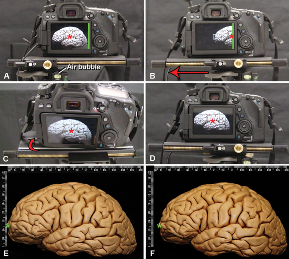
Technique for 3D documentation for macroscopic pictures of a formaldehyde-fixed brain, lateral view. The basic principle is to take one picture for each eye focused on the same center. All the pictures are taken with the 100 mm lenses modifying the distance to the object to achieve far away or closer views. ( A ) The sliding plate has to be parallel to the floor, to ensure this, the air bubble (which must be located in the middle square of the three-way tripod head) needs to be in the middle, and the sliding plate completely positioned toward the right side. The center of the screen is the reference to take the picture (red asterisk). The edge of the camera screen is marked with a green line. The first picture to be taken represents the right eye view. ( B ). After taking the picture, the sliding plate has to be moved to the left (red arrow) until the right border of the photography camera screen (green line) is located in the previous center of the right picture (red asterisk) or half-way through that distance. Complex calculations have been described to know the exact horizontal displacement needed between the two pictures to achieve a perfect stereoscopic pair of images taking into account the distance of the camera to the object, but the method described here has been proven very efficient in obtaining 3D for anatomical dissections. ( C ). To take the second picture (left eye view), the camera must be slightly rotated to the right (red arrow) until the previously chosen center of the right eye picture is also the center of the left eye image (red asterisk). Having both right and left images with the same focus center achieves stereoscopic images. ( D ). View of the left eye image: ( E ) observe in this picture that the green asterisk is closer to the vertical rule than observed in ( F ) (right eye view), both images are slightly different. 3D, three-dimensional.
Standard camera settings should include simultaneous capture of JPEG (Joint Photographic Experts Group) and RAW formats, with images acquired in manual mode using image sensitivity ISO-100, aperture F-stop 32, autobalance, and autofocus. Exposure time (e.g., shutter speed) is variable depending on the nature of the dissection and correlated lighting constraints. Without supplemental lighting (e.g., beyond the ring light), superficial fields are optimally captured at 1- to 2-second exposure times which can be reduced if ambient or supplemental lighting is robust, or increased to 6 to 8 seconds to acquired deep shots of poorly lighted regions (which may also require the addition of semifocused high-intensity indirect lighting sources).
Final HDR images are generated in postprocessing by combining three images per “eye” that are identical in all parameters, save for the shutter speed, which is modified to provide underexposed, normal, and overexposed images (e.g., 1/4, 1, and 4 seconds). Speeds will vary by context, but the three speeds selected for a given shot should be reproduced exactly for left/right stereoscopic pairs, resulting in a total of six images per shot, three left/right pairs, each of which has a shared shutter speed.
Endoscopic Considerations
Endoscopic pictures are acquired via 0-degree endoscope and recording system. As the endoscope lacks a tripod analogue, care must be taken to establish a point of mechanical support, for example, in endoscopic endonasal picture in the nostril to establish the axis-of-rotation, allowing the left/right pairs to be taken at an appropriate horizontal offset (e.g., 2–3 mm), while maintaining the correct center point and avoiding vertical displacement ( Fig. 4 ). Care is taken to avoid vertical displacement as the pictures need to be completely parallel to have the best 3D view by having support completely horizontal to the floor when rotating the picture.
Fig. 4.
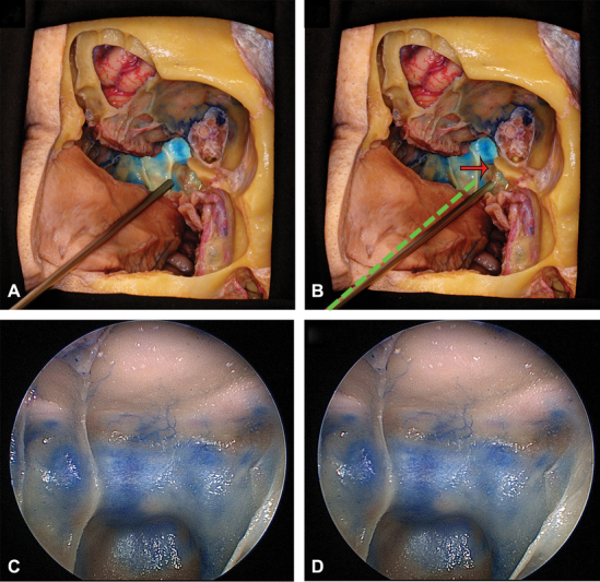
Endoscopic technique to take 3D images, oblique section of the nasal cavity and cranial base. The endoscope has been introduced through the left nostril. ( A ) represents the endoscope positioned to take the picture of the left eye view and in ( B ) the endoscope was slightly moved to the right (red arrow) to take the picture representing the right eye view. The green dotted line represents the initial position of the endoscope, which is rotated at the nostril level. For any other endoscopic pictures, which are not endonasal, another fixed axis of rotation has to be chosen. ( C ) and ( D ) represent endoscopic pictures of the sphenoid sinus taken with the endoscope when placed in A and B. 3D, three-dimensional.
Postprocessing
HDR techniques are recommended for improved quality and visualization of anatomic details ( Fig. 5 ). Each three-image left/right pair is merged using with Photomatix Pro 6.1.1, (HDRsoft , Brighton, United Kingdom), with contrast, brightness, and color modification as required. Additional enhancement of photo coloration or lighting is best achieved using Adobe Bridge (Adobe, Mountain View, United States), with RAW images modified prior to exportation as TIFF or JPEG for final adjustment of size and/or resolution files in Adobe Photoshop (Adobe, Mountain View, United States; minimum 300 dpi).
Fig. 5.
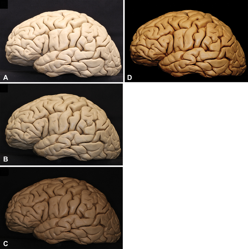
HDR technique. Three pictures are uploaded in Photomatix Pro 6.1.1, one considered overexposed ( A ), one presenting medium time of exposure ( B ) and the last one underexposed ( C ) the software fuses all images and provides a final image with improved contrast and brightness as observed in ( D ). The final images can be used in 2D or 3D projection. HDR techniques are recommended although not mandatory for stereoscopic presentations. 2D, 3D, two-dimensional; 3D, three-dimensional; HDR, high-dynamic range.
3D Presentation Systems
Dual 2D Projectors (Passive 3D)
Standard passive 3D presentation utilizes parallel projectors paired to polarized 3D glasses, as previously described ( Fig. 6 ). 10 12 Each projector exclusively displays one “eye” via a specific polarization filter; when paired with the polarized 3D glasses, light is filtered such that each of the viewer's eyes receives only images from the appropriate projector, resulting in stereoscopy. Of note, a silver screen is required for presentation, as it preserves light polarization upon reflection. 12 15 After preparing the final paired images in left/right orientation using PowerPoint, the presenter's computer is connected via HDMI to a splitter box and ultimately the paired projectors, resulting in each projecting the correct image in isolation. Prof. Rhoton's laboratory typically used a PowerPoint page size custom setup 8.4 inch × 3.15 inch (width and height respectively) to place both images side by side (approximately 4:3 aspect ratio per image). The images are placed side by side in the presentation ( Fig. 6D ); the right eye image on the right side of the page, and the left eye image on the left side of the page. The image size usually does not have to be modified in the dual projector system. Modern projectors are typically capable of high-definition presentation, and so the preferred format has evolved to 16:9 per image, resulting in an overall 32:9 aspect ratio.
Fig. 6.
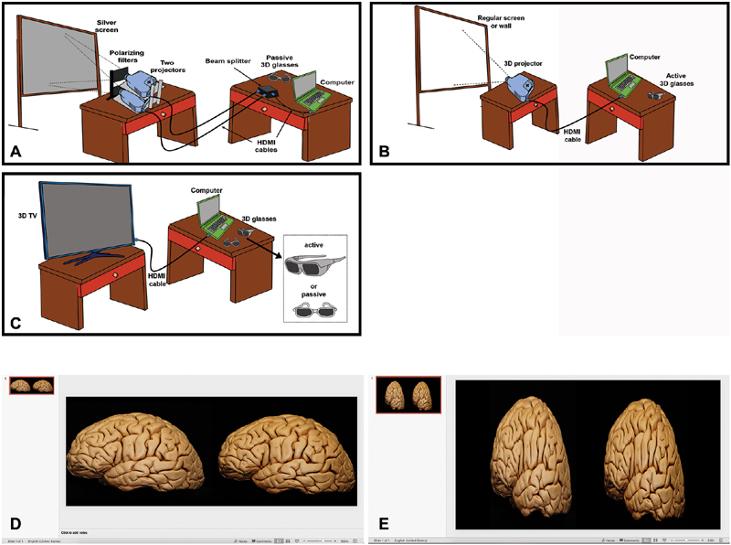
3D display. ( A ) Illustration representing the setup for 3D display with two projectors and a silver screen. The computer is connected with a HDMI cable to a beam splitter which is connected to two regular projectors. Each one of them projects the right and left eye views through two polarizing filters to a silver screen. The 3D experience is provided with passive 3D glasses. ( B ) Setup for 3D display with 3D projector. The computer is connected with a HDMI cable to a single 3D projector which overlaps and projects both images to a regular screen (white) or a wall. In this case an active glasses are required to provide the 3D experience. ( C ) 3D TV setup. Active or passive glasses may be required depending on the TV model. ( D ) Template setup for presentations with 2 projectors and using hand-held devices. In this setup the pictures usually do not have to be reduced horizontally. ( E ) Template setup for 3D projector and TV, the images are reduced horizontally to half of their original width. 3D, three-dimensional; HDMI, high-definition multimedia interface.
Hand-held stereoscopic devices can be used to quickly check the 3D in a personal computer with a side-by-side image in a PowerPoint presentation with this page setup, with no need of a projection system ( Supplement 1E : available online only).
Single 3D Projector (Active 3D)
In this arrangement, a single HDMI output from the presenter's computer to a 3D-capable projector is used ( Fig. 6 E ; Supplement 1E : available online only). The PowerPoint slide page setup is 16 inch × 9 inch. Each image must be compressed to 50% width in the presentation and placed side by side which looks elongated when not projecting in 3D. The projector automatically reexpands the images to the real anatomical dimensions. For some active projectors the dimensions of the PowerPoint presentation work better with 9 inch × 7.5 inch. A standard screen is used; however, active 3D glasses are required. There are different technical specifications and models of the 3D glasses, which must be both compatible with the projector and appropriately charged. From a technical perspective, “Active 3D” functions by rapidly alternating the left/right images projected, while synchronously opening/closing corresponding “electronic shutters” in the active glasses. These are general recommendations but the page setup may change slightly for different projectors.
3D Television (Active or Passive 3D)
3D-capable televisions require a single HDMI output from the presenter's computer which in turn is displayed using the passive or active glasses ( Fig. 6 ). The presentation format is the same as with the 3D active projector.
Discussion
Mastery of neuroanatomy is a foundational principle of all neurosurgical education, and a life-long goal for surgeons at every training level. Key to maintaining the craft of neurosurgery and excellence in practice are highly accurate and detailed core resources, best exemplified by the Rhoton Collection. 5 Although Prof. Rhoton's contributions are truly singular, the field of neurosurgery will continue to evolve beyond the terrain he so diligently mapped out, and as new techniques are developed and refined, the need for investment in neuroanatomy and maintaining a legacy of neuroanatomical study will only grow. With this outlook in mind, the central objective of this work was to provide an extensively detailed compendium of resources documenting the nuances of advanced neuroanatomy that, until Prof. Rhoton's passing, were orally transmitted between his fellows and went largely unpublished. 9 10 12
In addition to provide a reference for these insights, we also sought to highlight several advances that have been developed in our laboratories that yield specimens, dissections, and images that are comparable in quality to Prof. Rhoton's work but that may facilitate easier adaptation by relative neophytes ( Table 2 ). Although silicone was preferred by Prof. Rhoton, we have learned that that latex—particularly with color augmentation—is a simpler and more reliable means of defining the vasculature. More specifically, latex comes ready-made, and is easy to manually inject even in small caliber vessels, whereas silicone requires multiple ingredients to be actively combined at the time of injection (base silicone, thinner, catalyzer, and powdered pigment) and is more challenging to perfuse. 12 16 Additionally, our adoption of rigid vessel cannulas in lieu of silicone tubes with silk ties has resulted in simpler and more reliable procedures for maintaining adequate vascular access throughout the flushing and injecting procedures. Finally, some of the technical nuances specific to endoscopic photodocumentation, and HDR image acquisition and postprocessing, are described for the first time, and we anticipate that we will helpfully inform the expansion of neuroanatomic resources in these niches.
Table 2. Differences between our current anatomical research techniques and the previous technique described at Prof. Rhoton's Laboratory.
| Topics | Prof. Rhoton's laboratory | The authors' current protocol | Advantages found |
|---|---|---|---|
| Injection | Colored silicone 15 | Colored latex | Easier injection, premixed and ready, less pressure required |
| Cannulation | With silicone tubes, silastic tubes, and pipette adapters 12 | With embalming stainless steel cannulas and arterial fixation forceps | Tighter around vessels, easier and quicker to cannulate, more stability |
| HDR pictures | Not described in Dr. Rhoton's literature as a technique, adopted by Prof. Rhoton's laboratory in 2011 | HDR using Photomatix Pro 6.1.1' | High-quality images; improvement of contrast and anatomical details |
| 3D projection and display | Described for dual slide projectors and computer system with dual projection and silver screen 7 15 | 3D projectors and 3D TV regularly utilized except for audiences that exceed 100 people in which silver screen and dual projection are required | Easier to set up, easier to transport |
Abbreviations: 3D, three-dimensional; HDR, high-dynamic range.
With these nuances in mind, we also emphasize several of Prof. Rhoton's core maxims which are vital to the implementation of advanced dissection techniques. Every step of the process must be executed with precision and fidelity to yield the most consistent, high-quality results. Many steps have been validated over generations of fellows, and faithful reproduction is strongly recommended, for example, an attempt to ensure embalming within 24 hours of expiration, or the careful prevention of tissue desiccation throughout the dissection and photography process. Other parameters are characterized by a safe range of variability, and with time and experience, a degree of artistry may be expressed by the dissector, as in the photographic arrangement, dissection, or in the selection of optimal photographic exposure times.
Within the dissection phase, Prof. Rhoton strongly emphasized the importance of following compositions: clean lines, sharply cut skin or dural edges, no bone dust or tissue debris visible, deliberately framed shots, and optimization of lighting (e.g., removing out-of-field soft tissue that might impair ideal documentation). Learning an anatomist's craftsmanship is perhaps the single most challenging aspect of dissection, and we encourage newcomers to embrace the inevitability of frustration. Early attempts will be time-consuming; initial photographs will be disappointing. Initially, a “trial run” of every dissection is strongly recommended, both to assist with planning a “storyboard” of shots that will be included in the definitive dissection, as well as to familiarize oneself with the specific challenges and nuances, of the region or approach under study without pressure. With time, acumen and efficiency will evolve rapidly, and higher complexity dissections can be attempted. transitioning from approaches or supratentorial exposures, to skull base or posterior fossa dissections and ultimately to the highly demanding facial, head and neck, and fiber-tract dissections.
In parallel to deliberately rehearsing and repeating dissections, photodocumentation is a vast skillset unto itself, and we encourage dissectors to extensively document all of their work, both to build experience, as well as to chart their improvements over time. 3D photography is challenging, but powerfully enhances dissection photographs and remains one of the most important signatures of neuroanatomic research as developed and refined by Prof. Rhoton. Further, the incorporation of HDR techniques truly elevates the quality of the final product, and was considered the universal standard by Prof. Rhoton since 2011. Although HDR is time consuming and not strictly necessary for stereoscopic or 2D presentations, the enhancements in image quality, detail, color, and contrast are highly compelling, and as HDR-capable devices become commonplace and expand to other media, such as headsets, the value of diligently acquiring HDR images in anatomic studies will only increase.
Another important consideration is the physical challenges associated with our recommended technique for 3D image acquisition at very close range. Manipulating or removing the ring flash, using a hand-held light source, and creatively positioning both the specimen and camera are recommended. Finally, postprocessing software may further facilitate the correction of these factors, ideally via Stereo Photo Maker (Muttyan, Japan), which was used throughout the Rhoton collection. By contrast, although it may be tempting to image capture using the operating microscope, it has a limited depth of field, and the image quality will be markedly diminished. Similarly, the few commercially available 3D-capable cameras remain technically inadequate to achieve truly high-fidelity 3D images whereas they can be useful in other settings, such as documenting a nonmicroscopic surgery in the operating room.
Regarding the choice of 3D presentation systems, a sensitivity to the target audience's needs is paramount. Dual projector passive 3D requires a more complex setup and expensive equipment, but the passive glasses are widely available, inexpensive, and most practical for larger audiences (e.g., >100 viewers). By token, single-projector active 3D systems are highly functional in the medium-sized audience range (e.g., 15–100 participants) but require more expensive glasses that need to be charged periodically. Finally, although a 3D television is easy to use for smaller audiences (e.g., <15 viewers), although they are rarely nowadays commercially available. There is always certain degree of uncertainty in 3D presentations as there are multiple components involved for an optimal 3D experience. The PowerPoint setup described in this paper is what the authors use regularly; however, small variations of these may be needed in different systems or for different equipment models. It is strongly recommended to try the best setup for 3D presentations in a given system, be familiar with the utilized system and try the 3D with enough time prior to a lecture (usually at least a day in advance and immediately prior). Slight variations in configuration may change the final projection dimensions and give unrealistic anatomical images. A detail that Prof. Rhoton always emphasized was to bring a backup for almost every component of the 3D projection system with the exception of the silver screen. In the case of an active system, this is greatly simplified with some extra glasses, a projector lamp and/or an additional backup projector. Another recommendation from Prof. Rhoton was to prepare a backup 2D presentation in case there was a problem with the 3D presentation or inadequacy of the screen dimension to the target audience with the principle that “it is better to present a good 2D than a bad 3D.”
Although we have extensively detailed the supplemental knowledge base required to carry out and document neuroanatomic dissections in the spirit of Prof. Rhoton's laboratory, the chief limitation of our study is reflected in the fact that a manuscript can be no substitute for experience in the surgical laboratory. Nevertheless, our goal in assembling these resources was to facilitate active engagement with neuroanatomy dissection, and potentially shorten the learning curve between one's introduction to the laboratory and the achievement of excellent results.
Conclusion
Perhaps the most profound lesson absorbed by Prof. Rhoton's fellows is that the true nature of neuroanatomic study is far more art than science and universally fraught with unpredictability. The step-by-step descriptions and key pearls and pitfalls provided here constitute a valuable guidebook that we hope will empower new research in many environments; however, the realities of dissection are those of both frustration and exhilaration, and we strongly recommend that trainees investing themselves in laboratory study embrace the painstaking labors alongside their rewards. Indeed, neuroanatomy in general and neurosurgical education in particular remain critical frontiers in our field, and the ultimate goal of this study was to codify an essential body of knowledge such that, in the true spirit of Prof. Rhoton's work, his techniques can be understood, studied, reproduced, and improved in surgical anatomy laboratories across the world.
Funding Statement
Acknowledgments The authors are grateful to the Neurosurgery Research and Education Foundation, for their extraordinary support of these research activities, as well as the legacy of Prof. Rhoton throughout the community of academic neurosurgery. The authors also acknowledge the support received from Mr. Shaun G. Heath, Mr. Joshua Lopez, and Dr. Michael Smith.
The Northeast Prof. Rhoton Skull Base Dissection Laboratory, Department of Neuroscience and Experimental Therapeutics, Albany Medical Center, Albany, New York received funds from the NREF through the Young Investigator Award 2017, given to M.P.C., and received grants from Medtronic, Stryker, and Storz.
The Mayo Clinic Skull Base Research Laboratory was partially founded by the Endowment for Education Research Award, awarded by the Mayo Clinic Foundation to M.J.L. (PI), and M.P.C. (collaborator).
This study was financed in part by the “Coordenação de Aperfeiçoamento de Pessoal de Nível Superior—Brasil (CAPES) - Finance Code 001” which contributed funding L.C.P.C.L. during his fellowship in the Skull Base Dissection Laboratory in the Department of Neuroscience and Experimental Therapeutics in Albany Medical Center, Albany, New York.
Footnotes
Conflict of Interest L.P.C. reports grants from Mayo Foundation, during the conduct of the study. M.P.C. reports grants from NREF, grants from Medtronic, grants from Storz, grants from CAPES, grants from Mayo Foundation, during the conduct of the study. L.C.P.C.L. reports grants from CAPES, during the conduct of the study.A.P. reports grants from Mayo Clinic, during the conduct of the study. M.J.L. reports grants from Mayo Foundation, during the conduct of the study.
Supplementary Material
References
- 1.Fernandez-Miranda J C. Prof. Albert L. Rhoton, Jr.: his life and legacy. World Neurosurg. 2016;92:590–596. doi: 10.1016/j.wneu.2016.06.028. [DOI] [PubMed] [Google Scholar]
- 2.Matsushima T. Rhoton and his influence on Japanese neurosurgery. World Neurosurg. 2016;92:608–613. doi: 10.1016/j.wneu.2016.06.032. [DOI] [PubMed] [Google Scholar]
- 3.Robertson J H. Dr. Al Rhoton, Jr.: friend, mentor, and colleague. J Neurol Surg B Skull Base. 2016;77(04):291–293. doi: 10.1055/s-0036-1584943. [DOI] [PMC free article] [PubMed] [Google Scholar]
- 4.Robertson J H. Rhoton and the United States. World Neurosurg. 2016;92:597–600. doi: 10.1016/j.wneu.2016.06.029. [DOI] [PubMed] [Google Scholar]
- 5.Sorenson J. The Rhoton collection. J Neurol Surg B Skull Base. 2016;77(04):294–296. doi: 10.1055/s-0036-1584944. [DOI] [PMC free article] [PubMed] [Google Scholar]
- 6.Timurkaynak E. Rhoton and his influence on Turkish neurosurgery. World Neurosurg. 2016;92:614–616. doi: 10.1016/j.wneu.2016.06.033. [DOI] [PubMed] [Google Scholar]
- 7.Tong X. Rhoton and his influence in Chinese neurosurgery. World Neurosurg. 2016;92:617–622. doi: 10.1016/j.wneu.2016.06.034. [DOI] [PubMed] [Google Scholar]
- 8.Wen H T, de Oliveira E. Rhoton and his influence in Latin America neurosurgery. World Neurosurg. 2016;92:606–607. doi: 10.1016/j.wneu.2016.06.031. [DOI] [PubMed] [Google Scholar]
- 9.Martins C, Alencastro L F, Campero A, Rhoton A., Jr Three-dimensional endoscopic photography of anatomic specimens. World Neurosurg. 2018;120:e730–e736. doi: 10.1016/j.wneu.2018.08.150. [DOI] [PubMed] [Google Scholar]
- 10.Martins C, Ribas E C, Rhoton A L, Jr., Ribas G C. Three-dimensional digital projection in neurosurgical education: technical note. J Neurosurg. 2015;123(04):1077–1080. doi: 10.3171/2014.10.JNS13542. [DOI] [PubMed] [Google Scholar]
- 11.Ribas G C, Bento R F, Rodrigues A J., Jr Anaglyphic three-dimensional stereoscopic printing: revival of an old method for anatomical and surgical teaching and reporting. J Neurosurg. 2001;95(06):1057–1066. doi: 10.3171/jns.2001.95.6.1057. [DOI] [PubMed] [Google Scholar]
- 12.Shimizu S, Tanaka R, Rhoton A L., Jr. Anatomic dissection and classic three-dimensional documentation: a unit of education for neurosurgical anatomy revisited. Neurosurgery. 2006;58(05):E1000–E1000. doi: 10.1227/01.NEU.0000210247.37628.43. [DOI] [PubMed] [Google Scholar]
- 13.Fernandez-Miranda J C. Prof. Rhoton: master and mentor. J Neurol Surg B Skull Base. 2016;77(04):288–290. doi: 10.1055/s-0036-1584945. [DOI] [PMC free article] [PubMed] [Google Scholar]
- 14.Matsushima T, Kobayashi S, Inoue T, Rhoton A S, Vlasak A L, Oliveira E. Albert L. Rhoton Jr., MD: his philosophy and education of neurosurgeons. Neurol Med Chir (Tokyo) 2018;58(07):279–289. doi: 10.2176/nmc.ra.2018-0082. [DOI] [PMC free article] [PubMed] [Google Scholar]
- 15.Cohen M, Astur DdaC, Kaleka C C. Introducing 3-dimensional stereoscopic imaging to the study of musculoskeletal anatomy. Arthroscopy. 2011;27(04):593–596. doi: 10.1016/j.arthro.2011.01.004. [DOI] [PubMed] [Google Scholar]
- 16.Sanan A, Abdel Aziz K M, Janjua R M, van Loveren H R, Keller J T. Colored silicone injection for use in neurosurgical dissections: anatomic technical note. Neurosurgery. 1999;45(05):1267–1271. doi: 10.1097/00006123-199911000-00058. [DOI] [PubMed] [Google Scholar]
Associated Data
This section collects any data citations, data availability statements, or supplementary materials included in this article.


