Abstract
Haptic feedback plays a key role in surgeries, but it is still a missing component in robotic Minimally Invasive Surgeries. This paper proposes a dynamic model-based sensorless grip force estimation method to address the haptic perception problem for commonly used elongated cable-driven surgical instruments. Cable and cable-pulley properties are studied for dynamic modeling; grip forces, along with driven motor and gripper jaw positions and velocities are jointly estimated with Unscented Kalman Filter and only motor encoder readings and motor output torques are assumed to be known. A bounding filter is used to compensate for model inaccuracy and to improve method robustness. The proposed method was validated on a 10mm gripper which is driven by a Raven-II surgical robot. The gripper was equipped with 1-dimensional force sensors which served as ground truth data. The experimental results showed that the proposed method provides sufficiently good grip force estimation, while only motor encoder and the motor torques are used as observations.
Index Terms—: Sensorless Grasp Force Estimation, Dynamic Modeling, Unscented Kalman Filter, Elongated Cable Driven Instrument, Surgical Robot, Minimally Invasive Surgery
I. Introduction
Surgical robotic systems provide improved freedom of movement, decreased surgeon’s tremor, reduced motion and 3-dimensional images, greatly extend the applications of minimally invasive surgery(MIS)[1], [2]. Haptic perception plays a key role in surgery, because surgeons traditionally use tactile information for diagnosis. Besides the potential loss of diagnostic information, the lack of haptic feedback in current medical robotic systems may lead to poor force regulation and resulting damage to healthy tissues. In other contexts, for example grasping and suturing, lack of haptic feedback may result in insufficient forces [3], [4], [5]. In current MIS systems, the surgeon’s ability to perceive valuable haptic information is severely impaired[4]. Researchers have proposed various methods to address the lack of haptic perception in robotic surgeries. The most direct approach is to use force sensors to measure the forces from instrument tips. However, due to the stringent size, cost, and environmental requirements of MIS, few force sensors can be directly used in operating rooms. Although various smart design of sensors broke the size limitation [6], [7], [8], due to the cost and the requirements of sterilization, they are still not widely available.
Force is measured through directly or indirectly measuring displacement change of the elastic element that is correlated with the force magnitude. A thorough discussion on force and tactile sensing techniques for MISs can be found in[4]. A completely sensorless way for grip force estimation is to utilize the fact that grip forces originate from motor torques in surgical instruments. Therefore, it is also possible to detect force by measuring motor outputs. This approach has advantages since it requires neither additional devices nor special design. Tholey et al. adopted the concept for 3-dimensional force estimation[9], and the disturbance observer was applied to sensorless force estimation [10]. However, the commonly used elongated cable driven surgical instruments are more complex in mechanics[11], and the long cable run through the mechanism introduces extra uncertainties such as cable stretch and cable-pulley friction.
In order to address this problem, both cable properties and cable-pulley properties have been thoroughly studied and modeled[12], [13], [14]; and the corresponding dynamic model was combined with Unscented Kalman Filter for surgical robotic manipulator positioning precision improvement[15]. In this paper, we focused on applying and extending these techniques to the elongated cable-driven surgical instruments for grip force estimation. The core contributions of the paper are:
We propose a dynamic model, UKF, and bounding filter based sensor-less force estimation method for elongated cable driven surgical instruments;
We implemented the proposed method and applied it to a 10mm gripper;
We validated the proposed method on the Raven-II robot and the experimental results showed that the proposed method provides good grip force estimation;
The paper is organized as follows: Section II introduces the dynamic model we constructed for force estimation; Section III explains the method used for sensor-less force estimation in detail; Section IV shows the experiment setup and the experimental results. Conclusions are summarized in Section V.
II. Elongated Cable Driven Surgical Instrument Dynamic Modeling
A. Dynamic Model
Dynamic models of manipulators describe the relationship between joint position, velocity, acceleration and system input forces, including input torque and external interaction forces.
Surgical instruments can be modeled as following[16]:
| (1) |
Where: A is the Inertia matrix of the manipulator; J is the Jacobian that projects external force into the reference coordinates; C(·) denotes the vector of Coriolis and centrifugal torques; G is the vector of Gravitational force; q, , are the manipulator position, velocity and acceleration, respectively; Fv,Fc are viscous friction and coulomb friction parameters, respectively; Γ,Fex are joint input torque and external torque (which is the grip force in our application) respectively.
The model shows that the friction terms and Coriolis and centrifugal terms increase the nonlinearity of the system and the time-dependency. In surgical instruments, the inertia is expected to be small. The precise measurement and modeling of all these terms is difficult in real surgical environments. For example, body fluids permeating the instrument mechanism can temporarily act as a lubricant and change friction parameters. We are studying probabilistic filters such as Non-linear Kalman Filters to track such parametric variations and also to correct for resulting errors in state estimation.
B. Cable-Driven Mechanism Model
Elongated cable-driven surgical instruments can generally be modeled as shown in Fig. 2; and an example of such instruments can be seen in Fig. 3. The cable-driven mechanism ensures surgical robots meet requirements such as narrow aspect ratio and high temperature sterilization; meanwhile, it also increases the complexity of the dynamic model. To be more specific, the cable-driven mechanism not only introduces extra friction between cables and pulleys, but also increases the uncertainties on joint positions, velocities and accelerations, due to the stretch of cable and backlash.
Fig. 2.
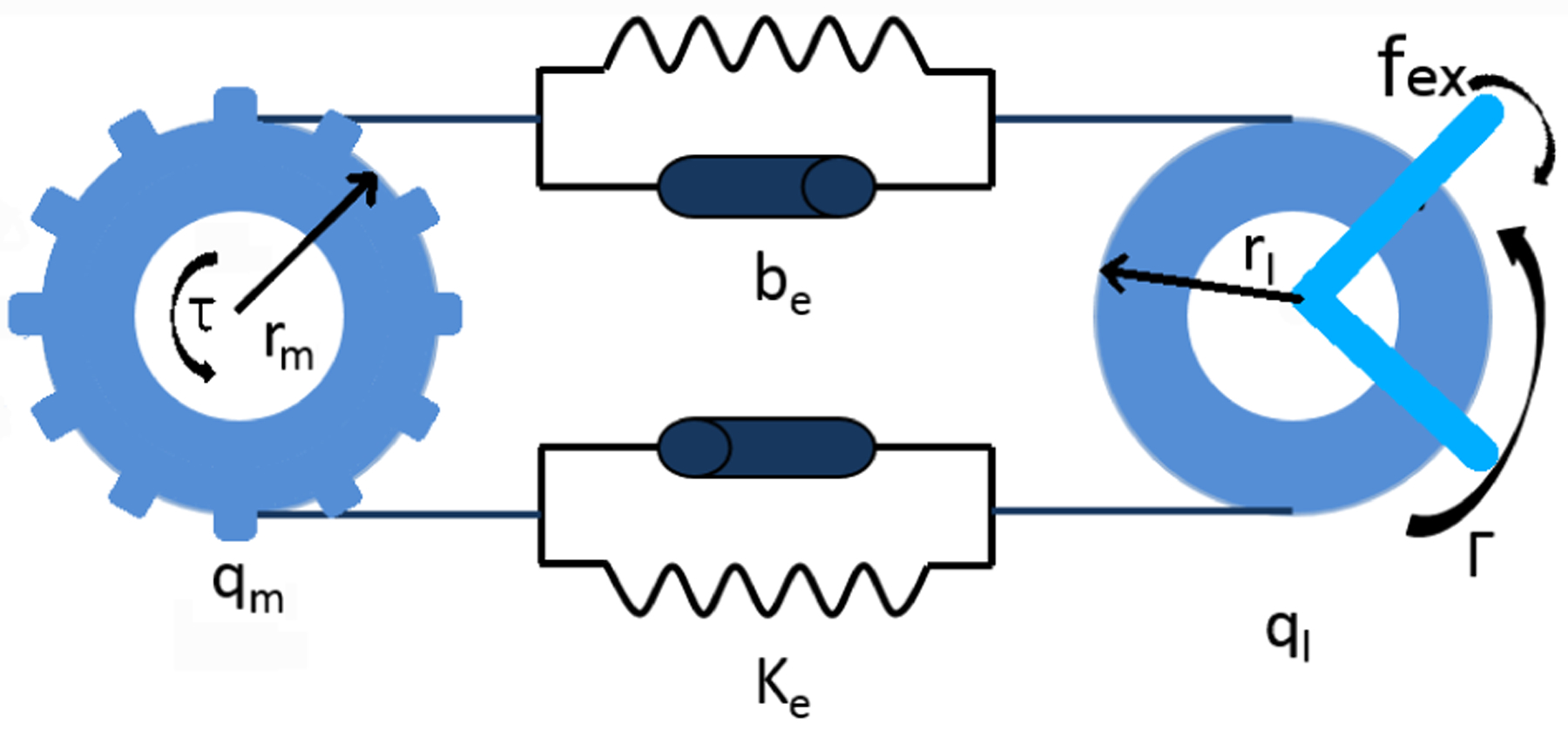
Elongated Cable Driven Surgical Instrument Model.
Fig. 3.
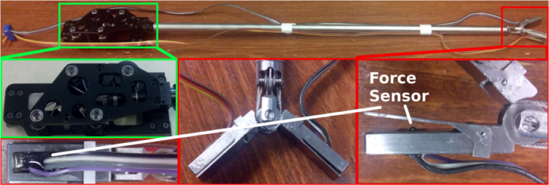
A 10mm Raven-II Gripper with Force Sensor. A Raven-II gripper was modified to equip force sensors on the jaws, as highlighted by the red rectangles; the gripper has four control degree of freedoms that correspond to roll, wrist pitch and two jaw pitches, respectively (highlighted by the green rectangles).
The dynamic model describing the relationship between driven motors and joints is:
| (2) |
Where: qm, , : denote motor position, velocity and acceleration, respectively; ql, : denotes link position and velocity; τ: denotes output torques from motors; Am: denotes the diagonal motor inertia matrix; Cm(·) denotes the vector of Coriolis and centrifugal torques of motor; Fvm,Fcm are viscous friction and coulomb friction parameters, respectively; rm, rl: are capstan radius of motor and link, respectively; γ: is the cable tension. The exponential spring-mass-damper model used here to depict cable properties is experimentally verified; and the cable stiffness and damping parameters ke,be can be measured by the equipment shown in Fig. 4. In this paper, ke = 2.2e4N/m,be = 950N · s/m.
Fig. 4.
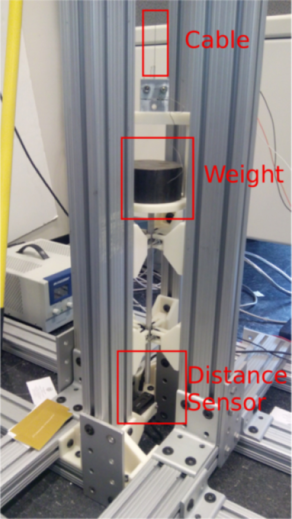
Cable Property Study Equipment. Different weights can be applied to cables for both static and dynamic property study.
Eqn. 2 shows that the output torque from a motor is partially consumed by its friction, Fm. Net torque is then converted to kinetic energy and passed to the link through the cable. The joint input torque from the cable is:Γ = γrl (Eqn.1). Eqns. 1 and 2 are the dynamic model of the elongated cable-driven surgical instrument.
C. Friction Analysis
Friction is a very complicated phenomenon arising at the contact of surfaces, and experiments indicate a functional dependence upon a large variety of parameters, for example: sliding speed, acceleration, critical sliding distance, temperature, normal load, humidity, surface preparation, and material combination [17]. For both cable driven surgical robots (such as Raven-II, the one we used to verify the proposed method; Fig. 5) and elongated instruments, cables go through multiple pulleys and pass the torque to the end effector; therefore friction between cables and pulleys plays a key role [14], [5]. Our previous study showed that the cable-pulley friction model is a function of cable tension, average individual wrap angle, and type and number of pulleys employed; and both the function and the coefficients are experimentally defined in [14].
Fig. 5.
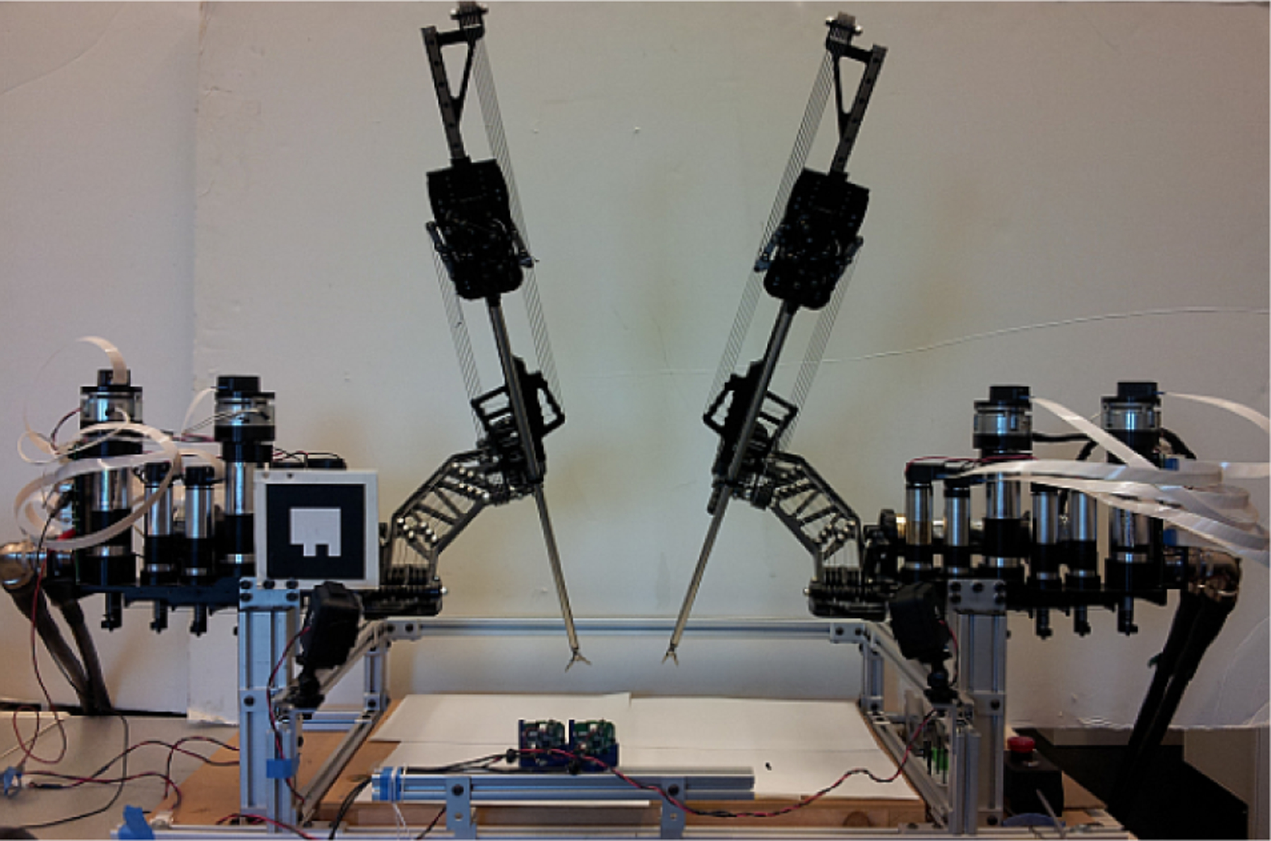
Raven-II Surgical Robot Platform. Raven-II is a full cable-driven surgical robot; both manipulators and instruments are powered by cables.
The motion axes in the instrument (the most distal axes in the manipulator’s serial chain) are qualitatively different from the more proximal axes near the base. In the base axes, large masses and cable low cable compliances (due to short cable runs) dominate the dynamics. In contrast, in the distal tool axes, the masses are very low and the cable runs much longer, therefore friction and compliance dominate the dynamics.
Although the friction model has been thoroughly studied and the coefficients were experimentally identified, system configuration and working environment constantly change in the surgical robotics scenario, which disturbs the coefficients. The ideal way of improving friction estimation precision is to dynamically estimate the coefficients. However, due to the fact that the observation dimensionality is much lower than the joint state dimensionality, it is difficult to online estimate the parameters without extra sensors. In order to improve the robustness and the precision of the proposed method, a bounding filter was applied to the grip force estimation (explained in Section. III-B in detail).
III. Dynamic Model Based Sensorless Grip Force Estimation
A. Unscented Kalman Filter for State Estimation
The Unscented Kalman Filter (UKF) was applied to the dynamic model for state estimation [18]. Although the computational complexity of UKF is as high as O(m3), where m is the size of the joint state vector; it is not a problem in the proposed method, because the size of the state vector is small and it does not grow with time. To be more specific, the state vector, x, can be stated as:
| (3) |
where i = 1,2,3,4 corresponds to the four control degrees of freedom. Mechanical interfaces to the DoFs are shown in the green rectangle in Fig. 3. The roll axis is index 1; the wrist is index 2; and the external forces for 1 and 2 are always zero since only the grip forces are estimated in the proposed method. The two grip jaws are index 3 and 4. Then the state space function of the system can be modeled as:
| (4) |
where f(·) corresponds to the dynamic model (Eqns. 1 and 2); H(x) = qm is the linear observation function since only the motor encoder is observable in the application.
The estimation process is visually explained in Fig. 6 as a Bayesian network: system states Xq, and Xf correspond to positions, velocities and grip forces, respectively; τ is the input torque from the motor; Xp is the parameters of the dynamic model and Z is the observation (motor position). Because many parameters in the dynamic model, such as friction coefficients, are changing with environmental changes, ideally, the parameters need to be estimated simultaneously in order to improve both precision and robustness. However, our experiments showed that jointly estimating both state variables and parameters does not easily converge. Therefore, in this study, the friction and cable parameters are considered constant. As explained in the previsou section, the friction and cable parameters do change in real surgical applications, we need to address this problem in our future work.
Fig. 6.

Sensorless Grip Force Estimation as Bayesian Network. system states Xq, and Xf correspond to positions, velocities and grip forces, respectively; τ is the input torque from the motor; Xp is the parameters of the dynamic model and Z is the observation, motor position
Because the dynamic model is in the form of differential equations, we used a fourth order Runge-Kutta integrator to solve the dynamic model in the time update process in UKF[19].
B. Bounding Filter for Robustness Improvement
Performance of the UKF is sensitive to the precision of both the state space function and the noise model. Although we have explicitly studied the properties of cable, and pulleys, in order to improve the accuracy of the dynamic model, both the precise identification of parameters and the exact knowledge of system process noise should not be assumed to be known in real-world applications, such as robotic surgery. More importantly, in the surgical instrument, motor and link position and velocity are “constrained” by cable stretch and inertias; but grip forces do not have such constraints. We also know that UKF propagates observation errors to state variables according to covariance estimation and the system state space function, therefore, system noise or measurement noise have much bigger impact on grip force estimation than on position and velocity estimations.
In order to improve the robustness and stability against noise, we used a bounding filter[20]. The bounding filter can improve estimation precision through exploiting the prior knowledge that while surgical instruments actively grip objects, the grip force does not exceed a value proportional to the output torque from the motors. The proposed bounding filter is mathematically explained as:
| (5) |
Where: denotes the estimation change from time point t −1 to t; denotes the estimation result on both system states and grip forces from UKF; η, ω are two constants; : is the output from the bounding filter (Figure 7) applied to the grip force estimation. In our implementation, the UKF runs at 10Hz, η = 0.3, and ω = 0.75.
Fig. 7.
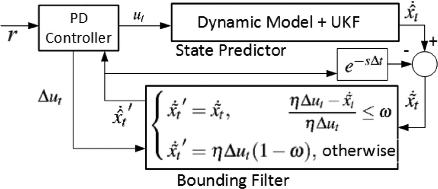
Bounding Filter for Improving Grip Force Estimation Precision and Robustness. denotes the system states and grip forces estimation of from UKF; e−sΔt denotes the time delay, therefore, denotes the estimation changes from time point t − 1 to t; η, ω are two constant; : is the output from the bounding filter.
IV. Experimental Result and Discussion
The proposed method was verified with a 10mm diameter, cable-driven surgical gripper (Fig. 3) on the Raven-II surgical robot (Fig. 5). The Raven-II robot is fully driven by cables, including a kinematic cable coupling between the manipulator’s insertion axis and the four instrument degrees of freedom. However, not all surgical robot platforms share the same mechanical design; therefore, in the proposed method, we only focused on the dynamic modeling of the instrument and the estimation of the grip force. In the experiments reported here, the manipulator holds still and only the instrument moves.
In order to obtain the grip force ground truth, the gripper was equipped with two low profile force sensors (FSS015WNSB, Honeywell) (picture is showen in Fig. 3, and the schematic drawing is shown in Fig. 8). Two aprons that rotate with respect to the jaw joint were added to the gripper to couple grasping contact forces to the sensor’s contact point. Once the location of the sensor is fixed, the relationship between the grip force and the torque exerted on the jaw is also fixed.
Fig. 8.

Modification to Gripper for Force Measurement. The left figure shows the modification we made to incorporate force sensors into the jaws for force measurement; the right figure shows the static calibration of the force sensor.
The static calibration of the force sensor was performed with weights (Fig. 8) and results are shown in Fig. 9. The calibration weights ranged from 0mN to 1176mN; and the linear fit results are:
| (6) |
The coefficient of determination R2 for the force measurement was 0.9965 for the left jaw and 0.9963 for the right jaw.
Fig. 9.
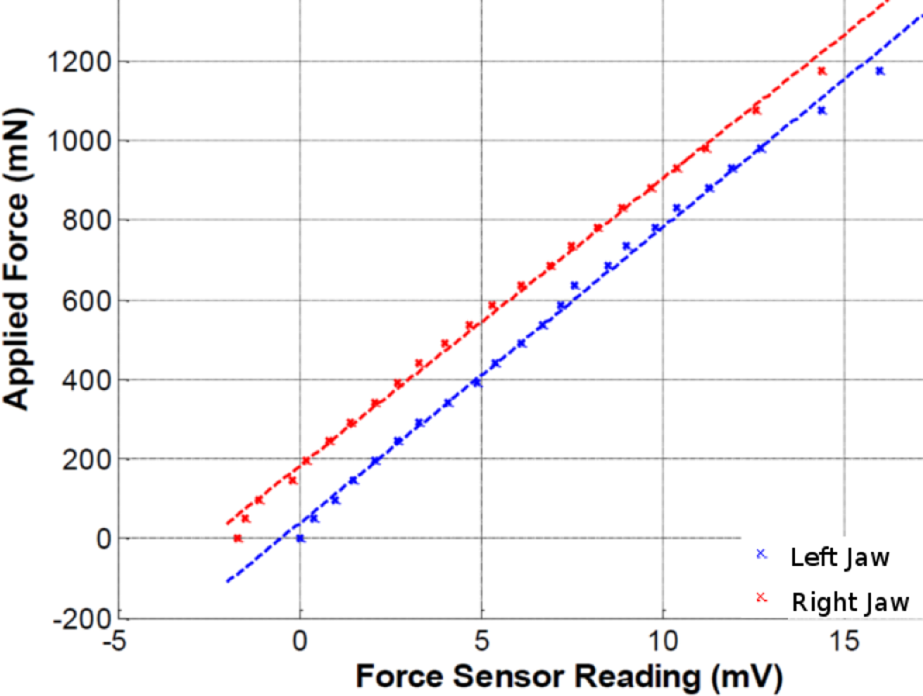
Force Sensor Static Calibration Results. The red and the blue lines correspond to the right jaw and the left jaw of the instrument, respectively.
A. Zero Grip Force Estimation
The proposed method was first verified in the zero grip force scenario: the jaws repeatedly open and close, without touching each other or any other objects. Therefore, the true grip forces should be near zero. The estimation result from the UKF and ground-truth from the grasp force sensors are shown in Fig. 10. Although the estimated forces are not exactly zero, an error histogram (Fig. 11) shows the magnitude of the estimation errors are small for both jaws. Although the static calibration results (Fig. 9) were highly repeatable and stable, the dynamic measurement from the sensors was noisy (Fig. 11). A Gaussian curve was fit to the sensor measurement in order to estimate the variance of the sensor noise. A smoothing filter adopted from [21][22] was applied to sensor measurements. The averaged errors, standard deviations, 99th percentile, and maximum values are compared in Table I. Although the averaged error from the sensor is much smaller than the estimated results, the estimated results are better on the other three parameters.
Fig. 10.
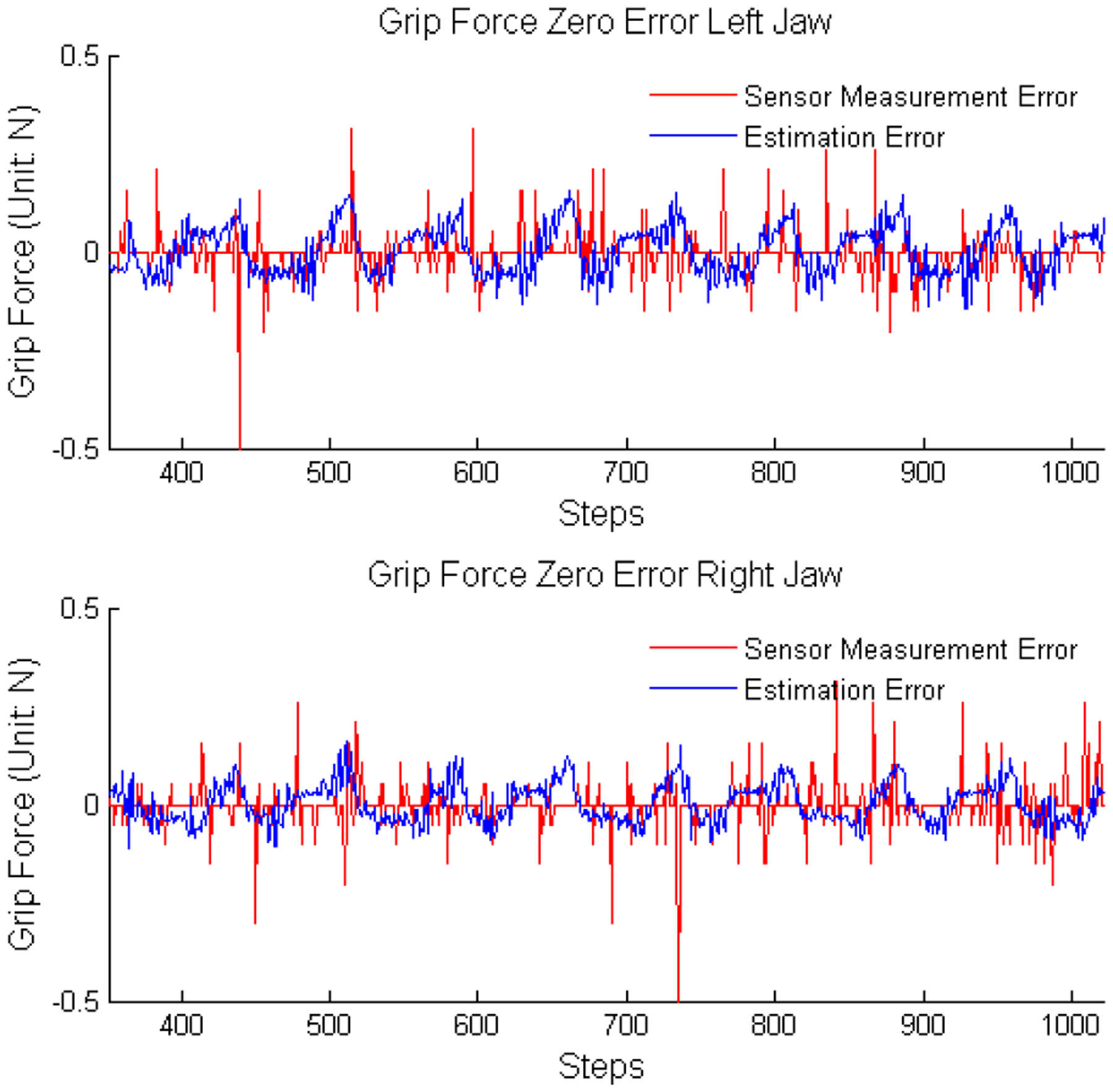
Sensor Measurement and Estimation Results Comparison. The jaws move without touching any objects, therefore, the grip force should be very near to zero all the time. The red and blue line showed the measured and the estimated force respectively.
Fig. 11.
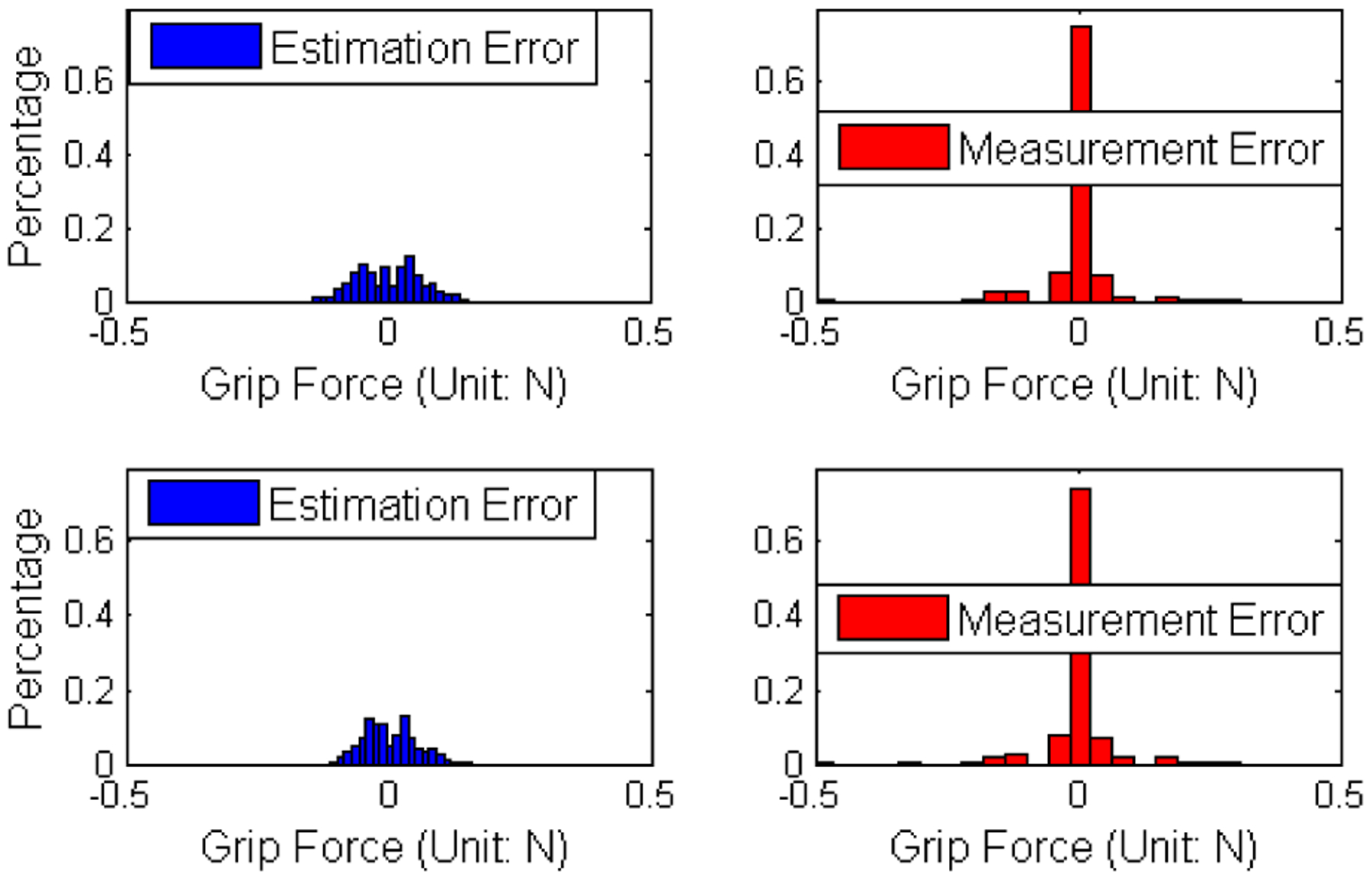
Sensor Measurement and Estimation Results Histogram Comparison. The zero grip force histogram comparison showed that the measured forces have smaller averaged errors and the estimated forces have smaller deviations.
TABLE I.
Estimated and Measured Zero Grip Force Error Comparison.
| Averaged | SD | 99%Value | Max | |
|---|---|---|---|---|
| Left Jaw Estimated | 0.0518N | 0.0329N | 0.1185N | 0.1524N |
| Left Jaw Measured | 0.0221N | 0.0501N | 0.1517N | 0.5058N |
| Right Jaw Estimated | 0.0412N | 0.0278N | 0.0935N | 0.1580N |
| Right Jaw Measured | 0.0236N | 0.0527N | 0.1573N | 0.6012N |
Note: SD: Standard Deviation; 99%value: the threshold of 99% of data
B. Non-zero Grip Force Estimation
The proposed method was applied to the instrument with non-zero grip force (Fig. 1). The gripper moved repeatedly and gripped a flexible tube, which is used to simulate blood vessels (yellow tube in Fig. 1).
Fig. 1.
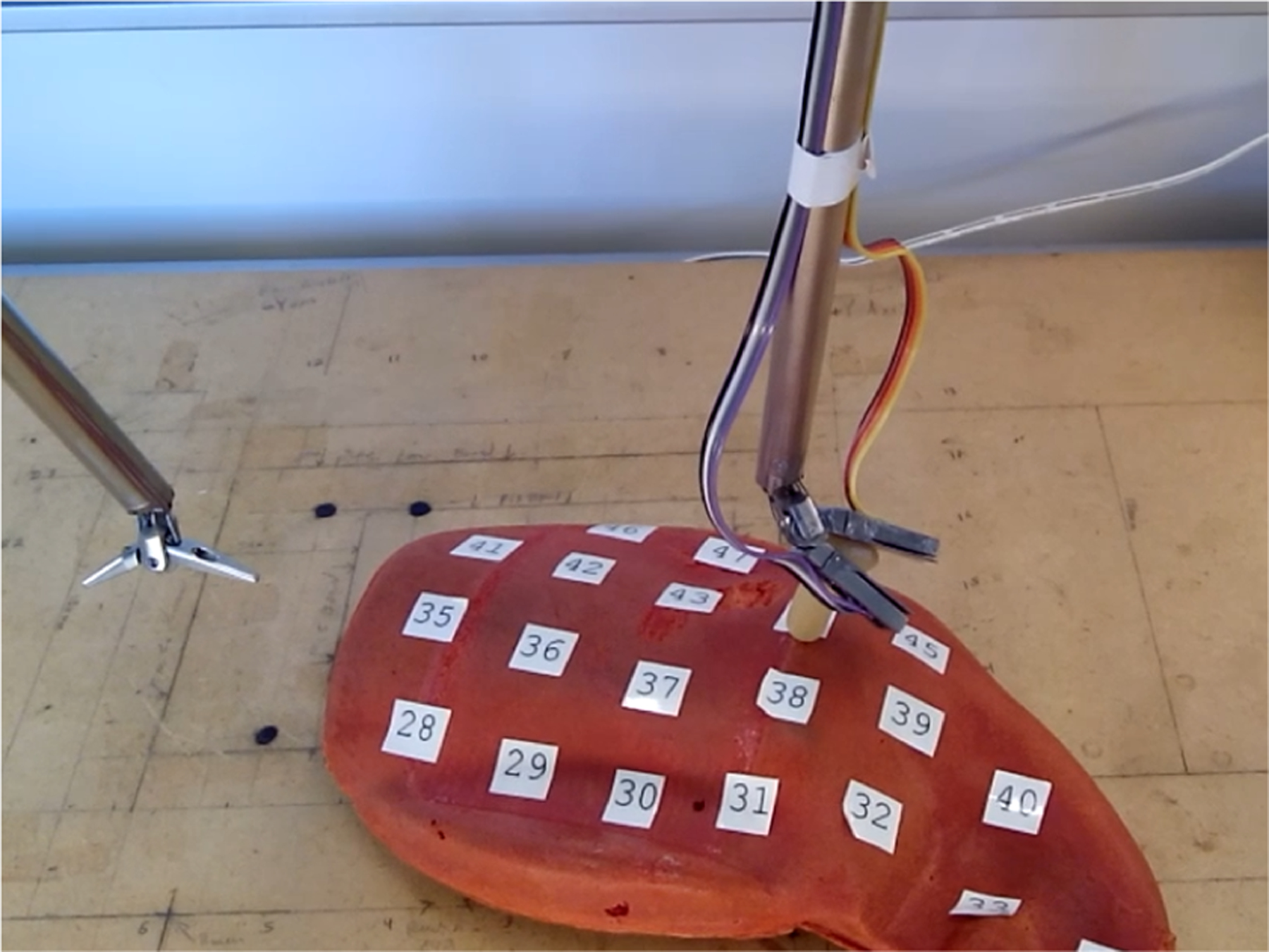
Sensorless Force Estimation Experiment Setup. The gripper moved repeatedly and grasped a flexible tube simulating a blood vessel.
The proposed UKF method was tested against both sensor measurements, and another similar method, proposed in [5]. Because of the facts that our experiments do not meet the quasi-static condication and we are lack of instrument of identifying parameters for the quasi-static method, the experimental results from the method is not even close to the ground truth, therefore, the results is not showd here to avoid confusion.
The comparison between the sensor measurements and the proposed UKF method is shown in Fig. 12. The UKF method can relatively precisely estimate the grip force. However, in some of the grasp cycles (e.g. Fig. 12, Right Jaw, t = {725,950,1100}) the proposed UKF method has a delayed response while the grip force decreases. Our guess is when the grip forces disappeared, the estimator still tries to project the observation errors to the state variables and therefore “stored” energy, then gradually it “realizs” the grip forces have disappeared. If our guess is correct, then the independent observation of jaw velocity will address the problem. However, equipping velocity sensors to the jaws are not much easier than directly mounting force sensors in MISs. If endoscope based gesture estimations or contact detection are available, for example from a vision system[23], we may be able to further improve the estimation precision without mounting sensors.
Fig. 12.

Comparison between Sensor Measured Force and Force Estimated by Proposed Method.
The difference (blue line) between the sensor measurement and the UKF estimation results are compared with measured grip force (red line) in Fig. 13. The difference histograms are fitted with a χ2 distribution in order to give a sense of the estimation precision. The averaged, 99th percentile and maximum differences, as well as the standard deviation are shown in Table II. The figures and the table show that the proposed method has good precision on grip force estimation, even though no extra sensors or equipment are used. Although the peak difference between the estimated forces and the measured forces reached 1N in Table II, the sensor measurements are not exactly the ground truth (see TableI). The experiment is also shown in the video attachment with the paper.
Fig. 13.
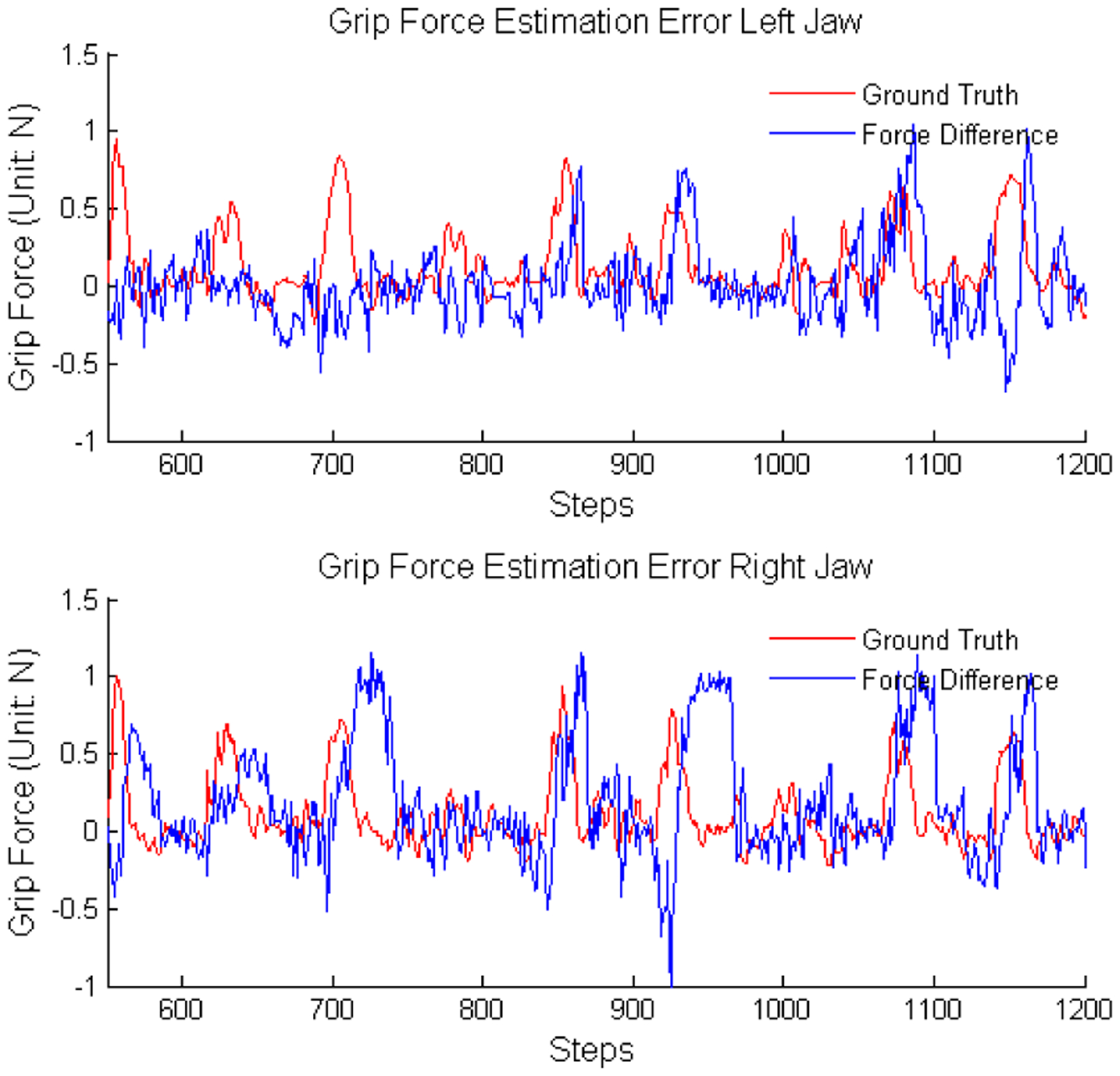
Sensor Measurement and Estimation Error Comparison. Difference between the estimated force and the sensor measured force are compared with sensor measured force, in order to show the ”delay phenomenon”.
TABLE II.
Difference between Sensor Measurement and Estimation.
| Averaged | Standard Deviation | 99%Value | Max | |
|---|---|---|---|---|
| Left Jaw | 0.1882N | 0.1991N | 0.6564N | 1.0589N |
| Right Jaw | 0.2823N | 0.3028N | 0.8562N | 1.1508N |
Significantly, the proposed method can be directly applied to existing elongated cable-driven instruments without extra sensors or hardware costs; it can also be easily combined with other estimation techniques, for example, vision based methods[24], in order to further improve estimation precision.
In this work, positions and velocities are also jointly estimated with grip forces, as they are critical components in grip force estimation. The estimation results are shown in Fig. 15. Although we do not have the ground truth for positions and velocities in this study, the dynamic model-based UKF for position estimation is reviewed in [15], [25].
Fig. 15.
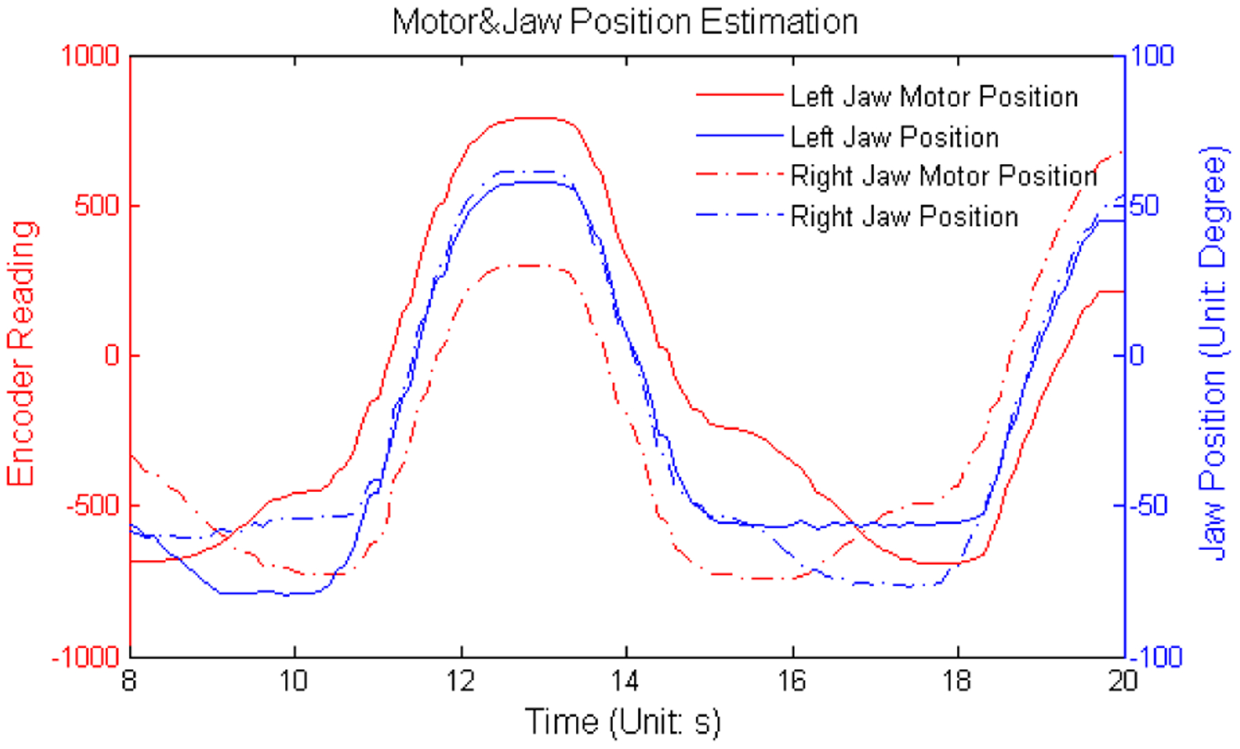
Motor and Jaw Position Estimation.
V. Conclusion
A dynamic model-based grip force estimator was proposed to replace force sensing in elongated cable-driven surgical instruments. In the proposed method, only motor output torques and motor encoder readings are needed for force perception and no extra hardware is required, in order to address the problem that force measurement schemes which require hardware modifications face significant adoption barriers due to sterilization and cost constraints.
A 10mm cable-driven gripper was equipped with 1-dimentional force sensors is used to validate the proposed method. Comparision between the estimation from the proposed method and the sensor measurement showed that the proposed method achieved good precision. If extra sensors, such as endoscopes, exists, a contact detector can easily correct the ”estimation lag” caused by insufficient observations in the proposed method. The proposed method still has limitations: it actually estimates the torqure on the jaw joint from the grip force, instead of the force; it is also sensitive to the dynamic model precision, which requires some tuning; and it does not consider the full 6-dimentional force or the cable-coupling effect. Moreover, in clinic usage, surgeons desire the perception of pressure to improve surgical safety, however, the output of the proposed method, force, is still abstract for them, and the conversion between the force and the pressure depends on contact position and contact surface area, therefore, additional measurements are required to fulfill their requirements.
Next, we will study the uncertainty of the estimated force, so the proposed method can be easily combined with other force estimation techniques, such as estimations of contacted tissue deformation, under the Bayesian framework. The combination with these techniques are also the topic of future work.
Fig. 14.
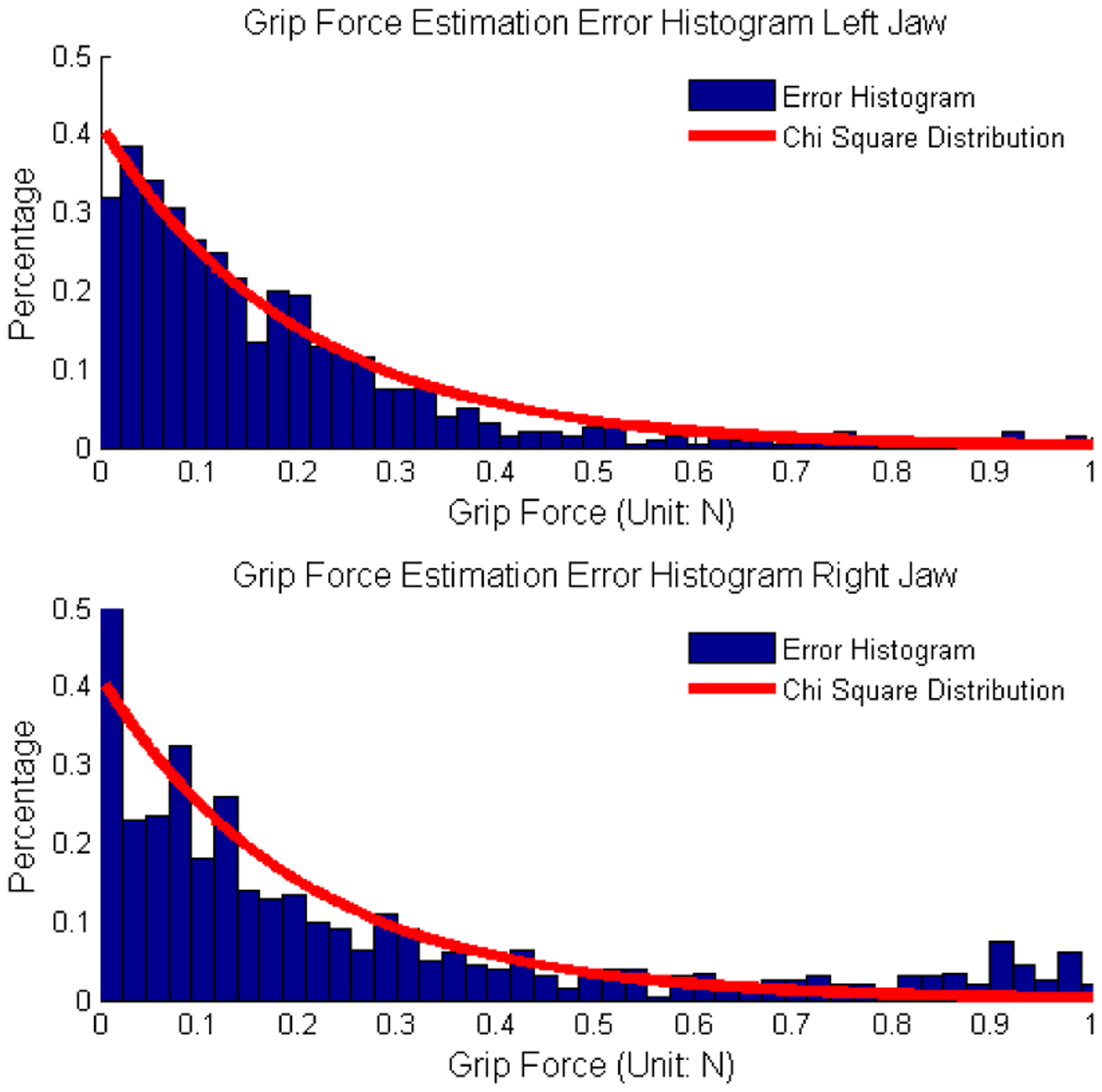
Sensor Measurement and Estimation Difference Histogram Comparison. Histogram are compared with χ2 distribution to model the estimation precision.
Acknowledgment
This work was supported by NIH grant 5R21EB016122-02 and the Korean Institute of Science and Technology (KIST); also, the authors would like to thank Biorobotics lab, University of Washington and the reviewers.
References
- [1].Mack MJ, “Minimally invasive and robotic surgery,” Jama, vol. 285, no. 5, pp. 568–572, 2001. [DOI] [PubMed] [Google Scholar]
- [2].Gomes P, “Surgical robotics: Reviewing the past, analysing the present, imagining the future,” Robotics and Computer-Integrated Manufacturing, vol. 27, no. 2, pp. 261–266, 2011. [Google Scholar]
- [3].Tholey G, Desai JP, and Castellanos AE, “Force feedback plays a significant role in minimally invasive surgery: results and analysis,” Annals of surgery, vol. 241, no. 1, p. 102, 2005. [DOI] [PMC free article] [PubMed] [Google Scholar]
- [4].Puangmali P, Althoefer K, Seneviratne LD, Murphy D, and Dasgupta P, “State-of-the-art in force and tactile sensing for minimally invasive surgery,” Sensors Journal, IEEE, vol. 8, no. 4, pp. 371–381, 2008. [Google Scholar]
- [5].Anooshahpour F, Polushin IG, and Patel RV, “Quasi-static modeling of the da vinci instrument,” in Intelligent Robots and Systems (IROS 2014), 2014 IEEE/RSJ International Conference on. IEEE, 2014, pp. 1308–1313. [Google Scholar]
- [6].Hammond FL, Kramer RK, Wan Q, Howe RD, and Wood RJ, “Soft tactile sensor arrays for force feedback in micromanipulation,” Sensors Journal, IEEE, vol. 14, no. 5, pp. 1443–1452, 2014. [Google Scholar]
- [7].Prasad SK, Kitagawa M, Fischer GS, Zand J, Talamini MA, Taylor RH, and Okamura AM, “A modular 2-dof force-sensing instrument for laparoscopic surgery,” in Medical Image Computing and Computer-Assisted Intervention-MICCAI 2003. Springer, 2003, pp. 279–286. [Google Scholar]
- [8].Vatani M, Engeberg ED, and Choi J-W, “Force and slip detection with direct-write compliant tactile sensors using multi-walled carbon nanotube/polymer composites,” Sensors and Actuators A: physical, vol. 195, pp. 90–97, 2013. [Google Scholar]
- [9].Tholey G, Pillarisetti A, Green W, and Desai JP, “Design, development, and testing of an automated laparoscopic grasper with 3-d force measurement capability,” in Medical Simulation. Springer, 2004, pp. 38–48. [Google Scholar]
- [10].Katsura S, Matsumoto Y, and Ohnishi K, “Modeling of force sensing and validation of disturbance observer for force control,” Industrial Electronics, IEEE Transactions on, vol. 54, no. 1, pp. 530–538, 2007. [Google Scholar]
- [11].Zhang X, Li S, and Guy R, “Sensorless haptic feedback in a surgical robot for telesurgery,” Journal of Medical Devices, vol. 5, no. 2, p. 027520, 2011. [Google Scholar]
- [12].Townsend WT, “The effect of transmission design on force-controlled manipulator performance,” Ph.D. dissertation, MIT, Cambridge, MA, 1988. [Google Scholar]
- [13].Miyasaka M, Haghighipanah M, Li Y, and Hannaford B, “Hysteresis model of longitudinally loaded cable for cable drivenrobots and identification of the parameters,” in Robotics and Automation, 2016. ICRA ’16. IEEE International Conference on, 2016. [DOI] [PMC free article] [PubMed] [Google Scholar]
- [14].L. A Miyasaka Muneaki, Matheson Joseph and Hannaford B, “Measurement of the cable-pulley coulomb and viscous friction for acable-driven surgical robotic system,” in Int. Conf. on Intelligent Robots and Systems (IROS), Hamburg, German, Oct. 2015. [Google Scholar]
- [15].Haghighipanah M, Li Y, Miyasaka M, and Hannaford B, “Improving position precision of a servo-controlled elastic cable driven surgical robot using unscented kalman filter,” in Intelligent Robots and Systems (IROS), 2015 IEEE/RSJ International Conference on. IEEE, 2015, pp. 2030–2036. [Google Scholar]
- [16].Khalil W and Dombre E, Modeling, identification and control of robots. Butterworth-Heinemann, 2004. [Google Scholar]
- [17].Berger E, “Friction modeling for dynamic system simulation,” Applied Mechanics Reviews, vol. 55, no. 6, pp. 535–577, 2002. [Google Scholar]
- [18].Van Der Merwe R, Wan E, et al. , “The square-root unscented kalman filter for state and parameter-estimation,” in Acoustics, Speech, and Signal Processing, 2001. Proceedings.(ICASSP’01). 2001 IEEE International Conference on, vol. 6. IEEE, 2001, pp. 3461–3464. [Google Scholar]
- [19].Carpenter MH and Kennedy CA, “Fourth-order 2n-storage runge-kutta schemes,” Nasa tm, vol. 109112, pp. 871–885, 1994. [Google Scholar]
- [20].Nahi NE and Weiss I, “Bounding filter: A simple solution to lack of exact a priori statistics,” Information and Control, vol. 39, no. 2, pp. 212–224, 1978. [Google Scholar]
- [21].Li Y and Olson EB, “Extracting general-purpose features from lidar data,” in Robotics and Automation, 2010. Proceedings. ICRA ‘10. 2010 IEEE International Conference on, May 2010. [Google Scholar]
- [22].Li Y and Olson E, “Structure tensors for general purpose lidar feature extraction,” in Robotics and Automation, 2011. Proceedings. ICRA ’11. 2011 IEEE International Conference on, May 2011, pp. 1869–1874. [Google Scholar]
- [23].Gong Y, Meng D, and Seibel EJ, “Bound constrained bundle adjustment for reliable 3d reconstruction,” Optics express, vol. 23, no. 8, pp. 10 771–10 785, 2015. [DOI] [PMC free article] [PubMed] [Google Scholar]
- [24].Reiley CE, Akinbiyi T, Burschka D, Chang DC, Okamura AM, and Yuh DD, “Effects of visual force feedback on robot-assisted surgical task performance,” The Journal of thoracic and cardiovascular surgery, vol. 135, no. 1, pp. 196–202, 2008. [DOI] [PMC free article] [PubMed] [Google Scholar]
- [25].Haghighipanah M, Miyasaka M, Li Y, and Hannaford B, “Unscented kalman filter and 3d vision to improve cable driven surgical robot joint angle estimation,” in Robotics and Automation, 2016. ICRA ’16. IEEE International Conference on, 2016. [DOI] [PMC free article] [PubMed] [Google Scholar]


