Abstract
The mechanism of [2 + 2] cycloadditions activated by visible light and catalyzed by bis-cyclometalated Rh(iii) and Ir(iii) photocatalysts was investigated, combining density functional theory calculations and spectroscopic techniques. Experimental observations show that the Rh-based photocatalyst produces excellent yield and enantioselectivity whereas the Ir-photocatalyst yields racemates. Two different mechanistic features were found to compete with each other, namely the direct photoactivation of the catalyst–substrate complex and outer-sphere triplet energy transfer. Our integrated analysis suggests that the direct photocatalysis is the inner working of the Rh-catalyzed reaction, whereas the Ir catalyst serves as a triplet sensitizer that activates cycloaddition via an outer-sphere triplet excited state energy transfer mechanism.
The mechanism of [2 + 2] cycloadditions activated by visible light and catalyzed by bis-cyclometalated Rh(iii) and Ir(iii) photocatalysts was investigated, combining density functional theory calculations and spectroscopic techniques.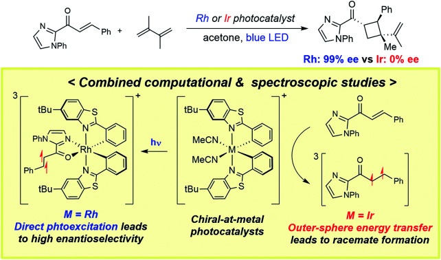
Introduction
Photocatalysts bearing transition metals have emerged as practical and valuable synthetic tools for organic chemists. These catalysts can form reactive radicals1–3 and triplet intermediates4,5 under relatively mild conditions and facilitate challenging transformations that are difficult to achieve by traditional synthetic methodologies. A successful photocatalytic reaction produces photogenerated radicals or triplet excited state intermediates in a well-controlled manner, while minimizing the production of undesired intermediates that result in byproducts and contaminate the catalyst. In this regard, there is a dire need for understanding the inner-workings of photocatalytic reactions to promote the rational design of novel photocatalytic transformations. A photocatalytic transformation is comprised of two reaction phases: (i) a photophysical phase that activates substrates via photoexcitation, intersystem crossing (ISC), and electron or energy transfer, and (ii) a reaction phase, wherein the activated substrates undergo desired bond formation and dissociation events. Unraveling the detailed mechanisms of photo-activated reactions requires advanced spectroscopic techniques such as time-resolved photoluminescence and transient absorption measurements,6 that have begun to be explored only recently.7 Computational studies8–11 have characterized reactive excited state intermediates, but mechanistic details of how the charge/energy transfer processes occur during the photochemical reaction remain poorly understood.
Asymmetric induction is of particular interest and constitutes a significant challenge in photocatalysis. Recent advances include the development of visible-light sensitized asymmetric [2 + 2] cycloadditions mediated by triplet excited energy transfer (TEET), which were pioneered by Bach,12–14 Yoon15–20 and Meggers.21–23 Photochemical [2 + 2] cycloaddition reactions engender a cyclobutyl functional group, that can not only produce valuable products but can also garner important intermediates en route to larger ring systems.24,25 Compared to photocatalysis utilizing single electron transfer (SET) pathways, photocatalytic transformations based on TEET mechanisms have broader substrate scope and withstand relatively mild reaction conditions.26–32 As such, there is growing interest in the development of asymmetric photocatalysts exploiting the TEET process, where the photocatalyst not only populates triplet excited state intermediates but also induces a chiral environment for stereoselective bond formation. Bach and co-workers adopted chiral Lewis acid and lactam photosensitizers to construct a hydrogen bonded substrate–catalyst complex to control the facial selectivity of intramolecular cycloaddition.33,34 Yoon and co-workers employed a dual catalysis approach, wherein the photocatalyst generates reactive intermediates and a chiral Lewis acid cocatalyst controls the stereoselectivity and enhances reactivity.20 Meggers designed chiral-at-metal platforms that enable visible-light-activated [2 + 2] photocycloadditions with pronounced enantio- and diastereoselectivities.21,35
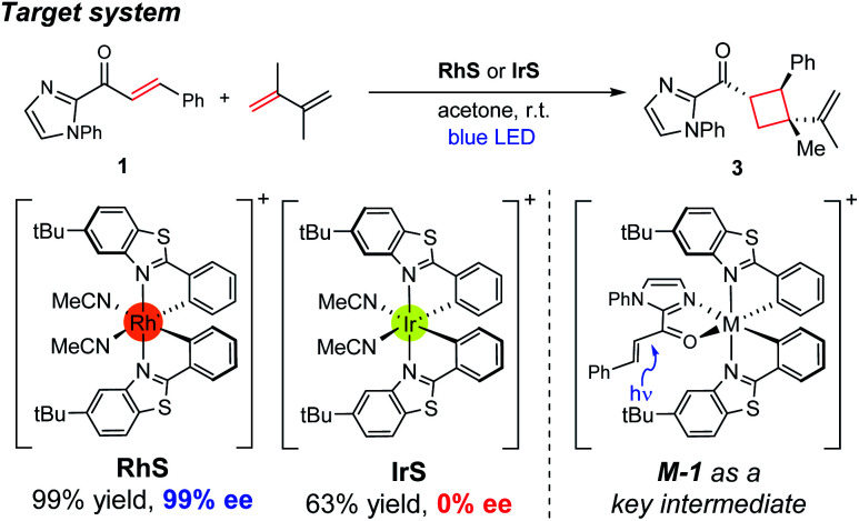
Herein, we investigated the detailed mechanism of an enantioselective [2 + 2] photocycloaddition reported previously (Scheme 1).21 The transformation utilizes a chiral-at-metal Rh catalyst (RhS) that enables the [2 + 2] photocycloaddition of enones and terminal alkenes with high enantioselectivity and diastereoselectivity. Interestingly, when using an analogous Ir catalyst (IrS), a racemic product mixture was obtained with a moderate yield. The different outcomes of the two transition-metal photocatalysts drew our attention, as the two isolobal metal centres were expected to exhibit similar reactivities. In order to comprehend these unexpected outcomes, we combined computational and spectroscopic analyses that characterize both the photophysical and the reaction phases of the reactions. Specifically, we delineated the mechanistic details of the photophysical phase of the reactions that activate the substrate–catalyst complex to access the triplet-state electronic manifold and rationalized the different outcomes from the Rh- and Ir-photocatalysts.
Scheme 1. Experimental conditions of the enantioselective [2 + 2] cycloaddition reaction investigated in this study.
Results and discussion
Catalytic cycle of direct photocatalysis
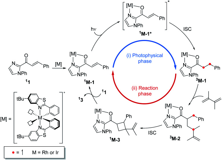
Fig. 1 summarizes the proposed photocatalytic cycle of the [2 + 2] cycloaddition. Previously, the direct photoexcitation of the catalyst–substrate complex was suggested as a key mechanistic event to explain the high enantioselectivity of the Rh catalyst.21 The reaction begins with the substitution of two acetonitrile ligands in the metal centers of the photocatalyst by the enone substrate 1 to afford the chelated metal complexes Rh–1, that absorbs blue light to access the singlet excited states 1Rh–1*. The generated singlet excited species undergoes fast internal conversion (IC) to the first singlet excited state (Kasha's rule36), followed by intersystem crossing (ISC) to form the triplet state intermediates 3Rh–1. The generated triplet excited state species undergoes a stepwise C–C bond formation with terminal alkenes to afford the diradical intermediate species 3Rh–2. A radical recombination step completes the formation of the [2 + 2] cycloaddition product 1Rh–3, which is a highly exergonic and likely barrierless process.
Fig. 1. The catalytic cycle of the direct absorption mechanism for [2 + 2] photocycloaddition. (M = Rh or Ir). The unpaired electrons are expressed with red dots.
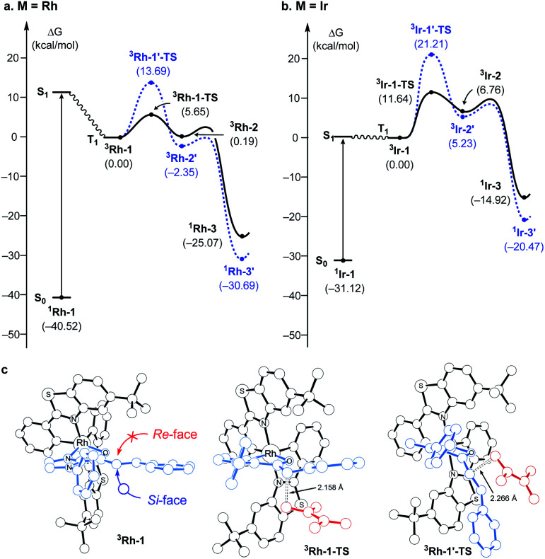
Fig. 2 summarizes the computed reaction energy profiles of the [2 + 2] cycloadditions, initiated from the photoexcited triplet intermediates. We used density functional theory calculations to analyze the reaction energy profiles (see the ESI† for the details). For the Rh photocatalyst, the computed energy profile explained the observed enantioselectivity, as shown in Fig. 2a. 3Rh–1 can engage the terminal alkene and the α,β-carbons of enone of the substrate 1. There are two possible faces of the metal-bound enone offered for the photocycloaddition reaction, as illustrated in Fig. 2c. The Si-face attack traverses the transition state 3Rh–1–TS with an activation barrier of 5.7 kcal mol−1, which is 8 kcal mol−1 lower in energy than the corresponding barrier of the Re-face attack at 13.7 kcal mol−1 (3Rh–1′–TS). This substantial difference in the activation energy is in line with the experimental observation of the Rh photocatalytic system, where an enantiomeric excess of >99% was observed. A comparison of the transition structures suggested that the Re-face imposes a significant steric demand on the approaching diene substrate at the corresponding transition structure (3Rh–1′–TS) due to a bulky tBu group of the LX ligand.8,22 The likely short-lived 1,4-diradical intermediates 3Rh–2 and 3Rh–2′ are found at 0.2 and −2.4 kcal mol−1, relative to the initial triplet intermediate (3Rh–1), respectively. A reverse ISC from the triplet (3Rh–2 and 3Rh–2′) to singlet biradical state followed by radical recombination completes the cyclization (1Rh–3 and 1Rh–3′). We were unable to locate the singlet biradical intermediate, as the C–C coupling occurs spontaneously.
Fig. 2. (a) Computed energy profile following the direct absorption mechanism with the Rh- and (b) Ir- photocatalyst; (black: Si-face attack, blue: Re-face attack, plain: favored, dashed: disfavored) (c) optimized structures of 3Rh–1, 3Rh–1–TS, and 3Rh–1′–TS.
In contrast, the computed reaction energy profile did not explain the observed racemic outcome from the Ir photocatalyst (Fig. 2b). The barriers for the initial C–C bond formations are notably higher with 3Ir–1–TS, that is located at 11.6 kcal mol−1 from the triplet state intermediate, whereas that of the alternative transition state 3Ir–1′–TS is 21.2 kcal mol−1. Albeit the computed activation barriers are 5–7 kcal mol−1 higher than those of the Rh–catalyst, the reactions are amenable at room temperature,37 suggesting that the Ir-photocatalyst also exhibits pronounced enantioselectivity. The discrepancy between the computational results and the experimental outcomes strongly suggested that the proposed mechanistic pathway is no longer valid for the Ir-photocatalyst. In the following, we demonstrate that 3Ir–1 is an off-cycle intermediate and the products are formed by a different mechanism, by means of the photophysical and electrochemical measurements and the computational analyses of the photochemical phase.
Photophysical and electrochemical studies
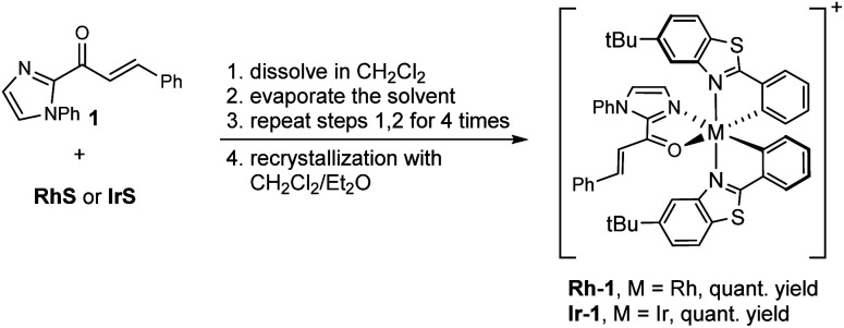
Our computational analysis of the mechanism of the [2 + 2] cycloadditions suggested that the reactions follow different pathways depending on the transition metal complexes used. To explore these possibilities, we prepared the intermediates Rh–1 and Ir–1 (Scheme 2) and studied their photophysical and electrochemical properties.
Scheme 2. Synthesis of Rh–1 and Ir–1. The complexes were prepared as their hexafluorophosphate salts.
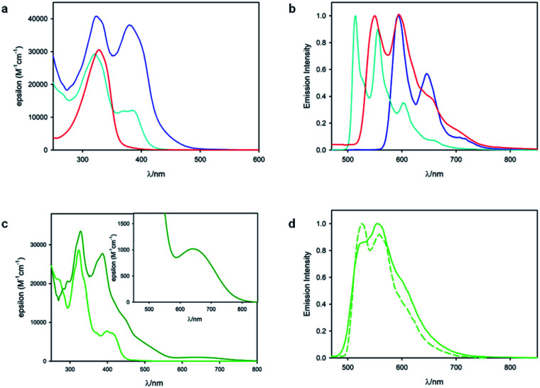
Fig. 3 shows the results of photophysical measurements of the substrate 1, metal complexes RhS and IrS, and substrate bound intermediates (Rh–1 and Ir–1), in CH2Cl2 at room temperature and in a CH2Cl2 : CHCl3 1 : 1 (v/v) rigid matrix at 77 K. The absorption spectra of RhS (cyan line, Fig. 3a) and Rh–1 (blue line, Fig. 3a) are quite similar and they exhibit bands at 380 nm and 385 nm respectively, which were assigned to singlet metal-to-ligand charge transfer (1MLCT) states based on our computational study (vide infra). Rh–1 presents an additional low-energy tail up to 500 nm. On the other hand, the absorption spectra of the two Ir(iii) metal complexes were quite different from each other (Fig. 3c): IrS exhibits the lowest-energy absorption band peaked at 398 nm, while Ir–1 has a weak absorption band centered at 640 nm with a tail up to 800 nm. The low-energy absorption band of Ir–1 can be tentatively assigned to a triplet metal-to-ligand charge transfer (3MLCT) state. As iridium possesses a much higher spin–orbit coupling compared to rhodium, a spin-forbidden electronic transition can be observed more easily.38
Fig. 3. (a) Absorption spectra of RhS (cyan line), 1 (red line) and Rh–1 (blue line) in CH2Cl2 at room temperature. (b) Normalized phosphorescence spectra at 77 K of Rh–1 (blue line, λex = 450 nm), RhS (cyan line, λex = 350 nm) and 1 (red line, λex = 350 nm) in CH2Cl2 : CHCl3 1 : 1 (v/v). (c) Absorption spectra of IrS (light green line) and Ir–1 (dark green line) in CH2Cl2 at room temperature. The inset shows the low-energy band of Ir–1. (d) Normalized phosphorescence spectra of IrS at RT (solid line) in de-oxygenated CH2Cl2 solution and at 77 K (dashed line) in CH2Cl2 : CHCl3 1 : 1 (v/v); λex = 400 nm. Of note, we did not observe the phosphorescence signal from Ir–1.
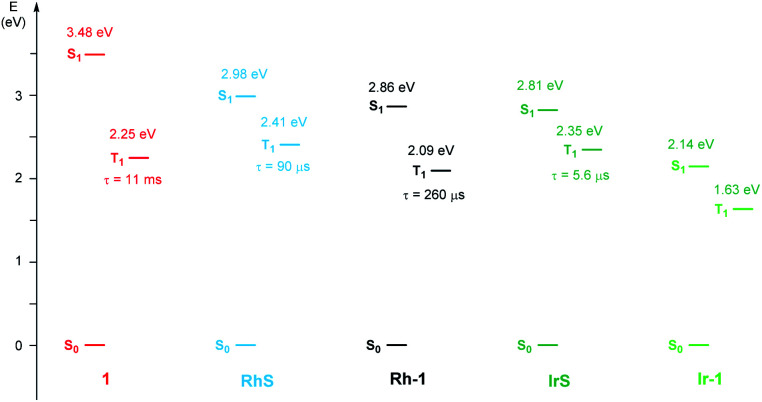
As far as emission is concerned, the enone substrate 1 exhibits a weak phosphorescence at 77 K (red line, Fig. 3b) with a lifetime of 11 ms. The metal complexes RhS and IrS display phosphorescence bands in a rigid matrix at 77 K with the maximum at 514 nm and 527 nm, respectively (Fig. 3b and d): the former presents a well-resolved vibrational structure and a longer lifetime (τ) of 88 µs compared to the latter (τ = 5.6 µs), suggesting a stronger LC characteristic of the electronic transition for the RhS compared to the IrS. The substrate-bound intermediates Rh–1 and Ir–1 exhibit distinctly different emissive properties: Ir–1 is not emissive both in deoxygenated CH2Cl2 solution at room temperature and in the rigid matrix at 77 K. We tentatively assign this dark state as 3MLCT, which rapidly decays to the ground state by non-radiative processes. This result agrees with the conclusions drawn from the computational studies that this state is not catalytically active (vide infra). Rh–1 displays a vibrationally structured phosphorescence band with a maximum at 593 nm at 77 K and a lifetime of 260 µs. Based on the vibrational structure and lifetime, this band can be tentatively assigned to a 3LC transition centered on ligand 1. Fig. 4 shows the values of the lowest singlet (S1) and triplet excited states (T1) evaluated using absorption and emission spectra of the analyzed compounds.
Fig. 4. Schematic Jablonski diagram for 1, RhS, Rh–1, IrS, and Ir–1 at 77 K.
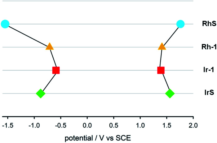
We also determined the electrochemical properties of the metal complexes (Fig. 5). RhS undergoes a chemically irreversible oxidation with Epa = +1.76 V at 0.5 V s−1 and a chemically reversible reduction at −1.55 V (partial chemical reversibility was attained at scan rate >2 V s−1). Rh–1 displays a chemically irreversible oxidation at +1.41 V and a chemically reversible reduction at −0.71 V. The MLCT characteristic of the Ir complexes is compatible with the measured electrochemical properties. The energy difference between the first oxidation and the first reduction is 1.98 V, much lower than in IrS (2.44 V). IrS undergoes a chemically reversible oxidation at +1.56 V and a chemically reversible reduction at −0.88 V. Ir–1 displays a chemically reversible oxidation at +1.39 V and a chemically reversible reduction at −0.59 V.
Fig. 5. Diagram of the redox potentials (E1/2 or Epa at 0.5 V s−1 in CH2Cl2 relative to SCE) of RhS (light-blue circle), Rh–1 (yellow triangle), Ir–1 (red square) and IrS (green diamond).
The redox potentials of the triplet excited state species precluded the photoredox activation of the substrates. Table 1 summarizes the estimated redox potentials of the four transition metal complexes. The redox potentials were computed using the ground state and the experimental ground state to triplet state energy gaps (Fig. 4 and 5).39 The estimated reduction potentials (Ered) ranged from −0.79 V to −0.26 V and the oxidation potentials (Eox) spanned from 0.86 V to 1.47 V. The redox potentials of the transition metal complexes were weak to reduce/oxidize the substrates effectively: the computed reduction (Ered) and oxidation potentials (Eox) of the substrate 1 are −1.69 V and 1.56 V vs. SCE, respectively and those of dimethylbutadiene are −3.68 V and 1.42 V vs. SCE, respectively.
Estimated redox potentials of the excited state transition metal complexesa.
| Compound | E([3M]+/[3M]) | E([3M]/[3M]−) |
|---|---|---|
| RhS | −0.65 | 0.86 |
| Rh–1 | −0.68 | 1.38 |
| IrS | −0.79 | 1.47 |
| Ir–1 b | −0.26 | 1.04 |
The unit of potential is V.
We used the computed ground-triplet gap (1.54 eV) for the estimation (Fig. 6c).
Computational studies of the excited state species
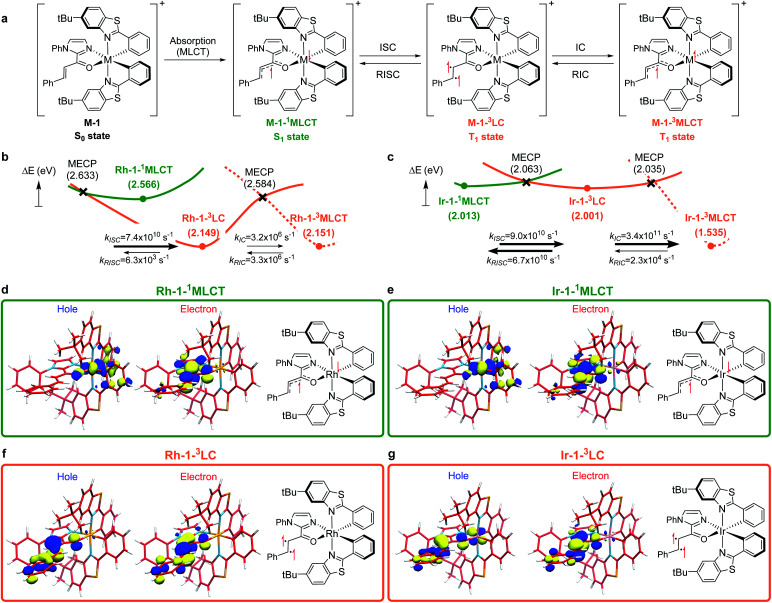
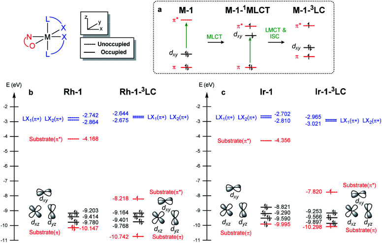
To understand the differences in the excited state electronic manifolds, Rh–1 and Ir–1 were further analyzed by means of excited-state electronic structure methods. The photophysical activation steps are summarized in Fig. 6a. The chelated metal complex species (M–1) consisting of M(iii)-d6 centres can absorb light to access singlet excited state species, that is subject to non-radiative internal conversion (IC) to the first singlet excited state species (S1). Our computational analysis suggested the S1 species bears a singlet MLCT characteristic (M–1–1MLCT), where the metal centre is formally oxidized to a M(iv)-d5 state and the ligand is reduced (vide infra). Intersystem crossing (ISC) mediated by the spin–orbit coupling allows the conversion of the singlet excited species to the triplet excited state species, wherein the alkene moiety of the enone substrate is activated to become a diradical, manifesting the characteristics of the ligand-centered (LC) triplet excited state (M–1–3LC). In the LC state, two independent electrons are localized at the π and π* orbitals of the enone while the metal centre is reduced by one electron. Once the substrate is activated to access the triplet LC state, the reaction phase becomes operational as long as the photophysical deactivation is slower than the activation of the cycloaddition reaction. Triplet LC states can proceed further to become a triplet MLCT state, that is denoted as M–1–3MLCT. Experimental evidence suggested the triplet MLCT states are prone to deactivation prior to engendering desired cycloaddition products.
Fig. 6. (a) The photophysical route to access the triplet LC and MLCT states. Computed excited state energy surfaces of (b) Rh–1 and (c) Ir–1. The renditions of natural transition orbitals of the identified excited singlet (M–1–3MLCT) and triplet state (M–1–3LC) species of Rh–1 (d and f) and Ir–1 (e and g). Filled circles represent the energy of the optimized geometries on the corresponding energy surfaces; crosses designate minimum energy crossing points (MECPs) of two energy surfaces. Electronic energies were computed at the (TD)CAM-B3LYP-D3/6-31G(d,p)/LANL2DZ level of the theory.
We utilized time-dependent density functional theory (TD-DFT) calculations of the excited state species to characterize the energetics and electronic nature of the photoexcited intermediate species that are implicated in the photochemical phase of the reaction. Firstly, we optimized the first singlet excited state geometries of the chelated metal complexes Rh–1–1MLCT and Ir–1–1MLCT. The computed adiabatic energies relative to those of the optimized ground state geometries are 2.57 and 2.01 eV, respectively, in good agreement with the energetics of singlet MLCT states measured from the emission spectra (Fig. 3 and 4). Natural transition orbital (NTO)40 analysis confirmed that the singlet excited state species bears a strong MLCT characteristic (Fig. 6d and e), where a metal d-orbital participates in the hole and the lowest π* orbital of the enone contributes to the electron state. The observation is in line with the orbital contributions to the singlet excited state (Table S3†): a singlet MLCT state species comprises HOMO to LUMO excitations, where the HOMO contains d-orbitals of the metal center and the LUMO consists of the π*-orbital of enone.
We also optimized geometries following the triplet excited state manifold bearing the characteristics of π–π* ligand-centered (LC) excitations (Rh–1–3LC and Ir–1–3LC) and the MLCT excitations (Rh–1–3MLCT and Ir–1–3MLCT). For the Rh complex, both the triplet LC and MLCT states (Rh–1–3LC and Rh–1–3MLCT) are lower in electronic energy by 0.4 eV than that of the singlet MLCT species Rh–1–1MLCT. For the triplet LC state, significant contribution from the substrate π–π* orbitals was observed, whereas the d–π* transition was dominant for the triplet MLCT state (Table S3†). The adiabatic electronic energy of the Ir-complex Ir–1–3LC was calculated at 2.00 eV from that of the optimized ground state geometry, which was nearly isoenergetic to that of the singlet MLCT state Ir–1–1MLCT. The triplet MLCT of the Ir complex (Ir–1–3MLCT) was 0.47 eV lower in energy than that of the singlet MLCT state (Ir–1–1MLCT) and the triplet LC state (Ir–1–1LC). Again, the renditions of NTO of the triplet species confirmed that the excited species possess the LC and the MLCT characteristics, as highlighted in Fig. 6f, g, and S1.† Similar to the Rh-complex, the d–π* transition in the 3MLCT state and the substrate π–π* transition in the 3LC state were identified (Table S3†). The energy difference between Ir–1–3MLCT and Ir–1–3LC explained the higher activation barrier of the first bond formation step in the [2 + 2] cycloaddition of 3Ir–1, than that of the 3Rh–1 (Fig. 3), as the direct photocatalysis using the Ir complex necessitates the presence of Ir–1–3LC that is higher in energy than Ir–1–3MLCT.
The calculated rates of ISCs and ICs suggested that the Rh-photocatalyst populates triplet LC states with efficiency, which explains the enantioselective [2 + 2] cycloaddition from the Rh-photocatalyst. The rates of ISC between the singlet MLCT and the triplet LC states were calculated based on Marcus theory,41 as summarized in Table 2. For the Rh-complex, the computed rate of ISC from the singlet MLCT Rh–1–1MLCT to the triplet LC state Rh–1–3LC was kISC (Rh) = 7.4 × 10¹⁰ s−1, whereas that of the reverse process was kRISC (Rh) = 6.3 × 10³ s−1. The ratio of forward and reverse ISC rates demonstrates that the intersystem crossing is an irreversible process. The computed rates of internal conversions between Rh–1–3LC and Rh–1–3MLCT were kIC (Rh) = 3.2 × 10⁶ s−1 and kRIC (Rh) = 3.3 × 10⁶ s−1, respectively. This finding indicated that the photophysical conversion of Rh–1–3LC to Rh–1–3MLCT is 4000-fold slower than the ISC from Rh–1–1MLCT whose lifetime is expected to be in the order of microseconds. The conversions between the singlet and triplet MLCT states were anticipated to be much slower. The computed rate of ISCs from Rh–1–1MLCT to Rh–1–3MLCT was 3.2 × 10⁵ s−1 and the rate of the reverse process was negligibly small relative to the other rates of ISCs and ICs. This finding manifested the El-Sayed rule of ISCs: both the singlet and triplet MLCT states share similar orbital symmetries (Fig. 6d, e, and S1†), in which the ISCs are inefficient.42 Of note, at the minimum energy crossing point (MECP) of Rh–1–1MLCT and Rh–1–3LC, the bond length of Cα–Cβ is 1.347 Å, which is close to that of the optimized ground state (Table S1†), indicating that the intersystem crossing occurs in the Marcus inverted region.43
Detailed parameters for the computations of kISC and kICa.
| Molecule | Transition | K | V | ΔG | Λ |
|---|---|---|---|---|---|
| Rh–1 | 1MLCT → 3LC | 7.4 × 10¹⁰ | 17.14 | −9.61 | 12.74 |
| 3LC → 1MLCT | 6.3 × 10³ | 17.14 | 9.61 | 12.74 | |
| 3LC → 3MLCT | 3.2 × 10⁶ | 7.56 | 0.03 | 20.06 | |
| 3MLCT → 3LC | 3.3 × 10⁶ | 7.56 | −0.03 | 20.06 | |
| 1MLCT → 3MLCT | 3.2 × 10⁵ | 0.83 | −9.58 | 28.94 | |
| 3MLCT → 1MLCT | 2.0 × 10⁻² | 0.83 | 9.58 | 28.94 | |
| Ir–1 | 1MLCT → 3LC | 9.0 × 10¹⁰ | 16.90 | −0.17 | 2.49 |
| 3LC → 1MLCT | 6.7 × 10¹⁰ | 16.90 | 0.17 | 2.49 | |
| 3LC → 3MLCT | 3.4 × 10¹¹ | 31.98 | −9.76 | 11.33 | |
| 3MLCT → 3LC | 2.3 × 10⁴ | 31.98 | 9.76 | 11.33 | |
| 1MLCT → 3MLCT | 6.5 × 101 | 0.11 | −9.93 | 42.41 | |
| 3MLCT → 1MLCT | 1.5 × 10⁻⁸ | 0.11 | 9.93 | 42.41 |
The unit of the rates is s−1. The units of electronic coupling and energy are cm−1 and kcal mol−1, respectively.
Based on the computations of the rates of ISCs and ICs of Ir–1, we concluded that the 3LC state of the Ir–substrate complex is deactivated before engaging in photocycloaddition. The computed rates of ISC from Ir–1–1MLCT to Ir–1–3LC was kISC (Ir) = 9.0 × 10¹⁰ s−1, whereas that of the reverse ISC from Ir–1–3LC to Ir–1–1MLCT was kRISC (Ir) = 6.7 × 10¹⁰ s−1. The singlet MLCT and triplet LC states of the Ir-complexes are isoenergetic, affording comparable forward and reverse rates. The internal conversion from Ir–1–3LC to Ir–1–3MLCT was anticipated to be a fast and irreversible process. The rate of internal conversion (kIC (Ir)) was computed as 3.5 × 10¹¹ s−1 which was comparable to that of intersystem crossings. The rate of the reverse process from Ir–1–3MLCT to Ir–1–3LC (kRIC (Ir)) was calculated to be 2.3 × 10⁴ s−1, that is 107-fold slower than that of the forward process. The finding suggested that the triplet LC state of Ir–1 (Ir–1–3LC) is short lived and cannot engage in the [2 + 2] cycloaddition with the diene.
Comparisons of the electronic structures of Rh and Ir systems
We demonstrated above that the triplet LC state of the Rh complex is kinetically stable, whereas that of the Ir complex is not. We further investigated electronic transitions within frontier molecular orbitals (FMOs) of both of the chelated metal complexes, which rationalized the differences between the 1MLCT and 3LC states of the Rh and Ir systems.
Fig. 7a highlights the electronic transitions that occur during the photochemical phase. In the electronic ground state, a metal complex M–1 features the characteristics of d6–octahedral transition metal complexes, wherein one of the d-orbitals of the metal center (dxy) constitutes the HOMO level and the π and π* levels from the enone substrate 1 constitutes one of the high-lying doubly occupied orbitals and the LUMO level, respectively. The MLCT from the metal dxy level to the π*-level of the ligand creates a M–1–1MLCT state, which formally oxidizes the metal center while reducing the ligand. The ISC promotes one electron from the π level of the substrate to the half-filled dxy orbital, resulting in the formation of the 3LC state (M–1–3LC). The reverse ISC (RISC) conveys the backward process, bringing back the singlet MLCT state. We may conceptualize the ISC and RISC processes comprising two independent processes: (i) the transition of an electron between the substrate π orbital to the singly occupied dxy orbital (ligand-to-metal charge transfer (LMCT) and metal-to-ligand charge transfer (MLCT)) and (ii) the spin-flip to convert between singlet and triplet states. Our computational results suggested that the spin–orbit coupling (Vsoc) for both Rh and Ir systems are comparable (Table 2). In this regard, the energy gaps of π–dxy and π–π* play important roles in the ISC and RISC processes, as the energy gaps determine the electronic energies of 1MLCT and 3LC states.
Fig. 7. (a) Electronic excitations and (b) frontier molecular orbitals of M–1 computed at the B3LYP-D3/cc-pVTZ(-f)/LACV3P** level of theory.
Fig. 7b and c summarize the energy levels of frontier molecular orbitals that participate in the photoactivated electronic transitions. We investigated d–π* gaps of the optimized singlet ground state geometries to approximate the gap of the singlet MLCT states. The computed d–π* gap of Rh–1 was 2.46 eV and that of Ir–1 was 2.00 eV, in qualitative agreement with the energetics of M–1–1MLCT states measured from the fluorescence spectra: the excitation energy of Rh–1 was 2.86 eV being 0.72 eV higher than that of Ir–1 (Fig. 4). The observed difference in dxy–π* gaps can be explained by the pronounced relativistic contraction of Ir that elevates the occupied d-levels of Ir and lowers the unoccupied π*-level of the ligand.44 The orbital energy difference between π–π* gaps of Rh–1 and Ir–1 is comparable: 3.50 eV and 3.66 eV, respectively. This is in line with the finding that the adiabatic energies of M–1–3LC states of both systems are comparable (Fig. 6). In short, our analysis of the FMOs highlighted that the labile characteristic of Ir–1 compared to Rh–1 originates from the higher dxy of the Ir center than that of Rh.
The mechanism of triplet energy transfer of the Ir photocatalyst
We further investigated substrate-chelated Ir(iii) complex Ir–1 with regard to its stability and reactivity to expand our insights into the mechanism of the Ir-catalyzed [2 + 2] photocycloaddition. The circular dichroism (CD) spectra of Ir–1 before and after irradiation with blue LEDs for 20 h under an inert gas atmosphere gave us information about the chiral stability under reaction conditions. In acetone as solvent, which we used as the main solvent for the [2 + 2] photocycloadditions, we were able to observe a slow racemization of the complex indicated by different heights of maxima and minima (Fig. S9†). The conjecture of decomposition upon irradiation as the reason for the distinct spectra was omitted due to the similarity of the curves as well as 1H-NMR measurements showing no major decomposition upon illumination in acetone (Fig. S9†). To further evaluate the possible photoracemization of IrS during a [2 + 2] photocycloaddition, we investigated the chiral stability of IrS in the presence of a large excess of 2-acyl imidazole substrate 1, by measuring CD spectra before and after illumination (Fig. S11†). The spectrum prior to irradiation strongly resembles the spectrum of Λ–Ir–1 indicating that the substrate-coordinated complex is formed instantaneously. Importantly, the CD spectrum after exposure to light looks almost identical, implying that an excess of substrate protects the stereogenic center of the complex against racemization. Therefore, a racemization of the iridium catalyst during photolysis can be excluded as a reason for the formation of the racemic [2 + 2] photocycloaddition product.
Ruling out the possibility of the direct photocatalysis pathway of Ir–1 prompted us to search for an alternative mechanistic pathway that can explain the racemic product formation from the IrS system. Mechanisms that include the bimolecular activation between substrate 1 and the diene without the chiral environment of IrS may lead to the racemic products. This includes two modes of activation of 1, either a redox pathway to furnish an open shell intermediate or an outer-sphere energy transfer pathway to access the triplet state of the substrate. We precluded the photoredox pathway, as the measured redox potentials of the metal catalysts and the catalyst–substrate bound complexes are not strong enough to oxidize/reduce the substrate 1 (vide supra). After much effort, we concluded that the triplet energy transfer pathway is the most likely mechanism for the Ir-photocatalysis that was substantiated by our experimental findings. First, we found that Ir–1 catalyzes the photocycloaddition of methyl cinnamate. As shown in Table 2, Ir–1 catalyzes the [2 + 2] photocycloaddition of (E)-methyl cinnamate (entries 1 and 3). No conversion was observed when the catalyst was omitted (entries 2 and 4). Since methyl cinnamate cannot coordinate to iridium, this finding strongly suggests that Ir–1 serves as a triplet photosensitizer and activates the cinnamate substrates to access the triplet excited state manifold. Of note, Reiser and coworkers recently reported that bis-cyclometalated iridium complexes can serve as effective photocatalysts for the photosensitized [2 + 2] cycloaddition of cinnamate esters.45
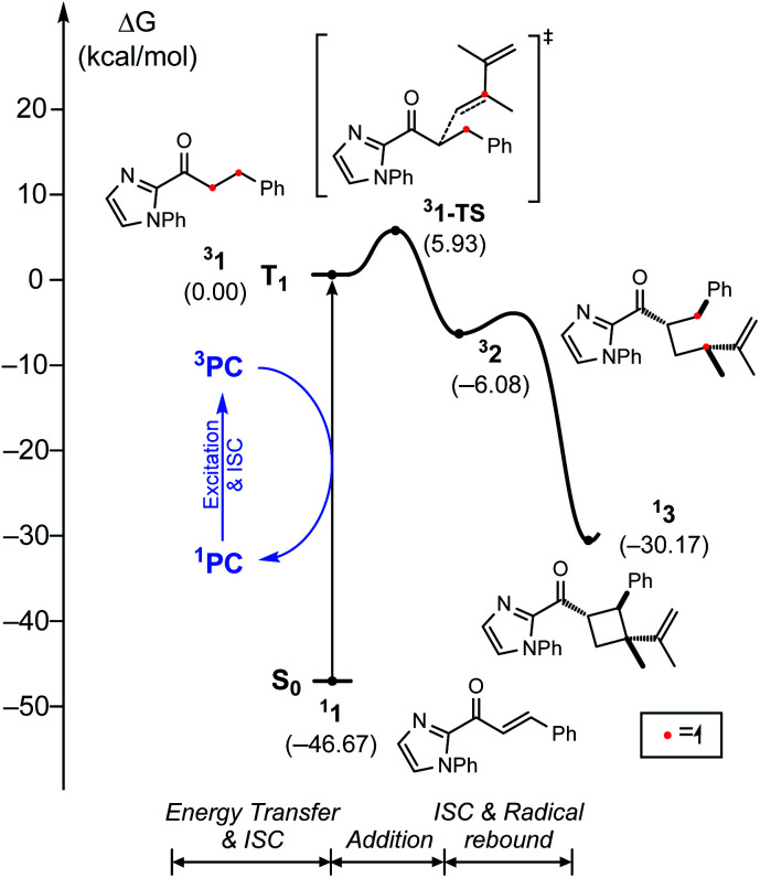
The triplet energy transfer mechanism is outlined in Fig. 8. First, the ground state photocatalyst 1PC absorbs visible light to become the singlet excited state 1PC*, followed by intersystem crossing that yields the photocatalyst in its triplet excited state 3PC. Then the 3PC transfers its energy to the enone substrate 11 to generate the triplet state species 31, which undergoes alkene addition to form a 1,4-biradical intermediate 32. Finally, ISC into the singlet state occurs yielding cyclobutane species 13.
Fig. 8. Triplet energy transfer mechanism for the [2 + 2] cycloaddition reaction.
Fig. 9 shows the computed energy profile following the triplet sensitization mechanism. Once the photocatalyst harvests light energy, an outer-sphere energy transfer can promote the enone substrate 11 to become a reactive triplet state species 31. We showed that Ir–1 may act as a photosensitizer in solution (Table 3), whose triplet excitation energy is 1.63 eV. IrS may be another candidate as the photosensitizer as it shows a sufficient triplet energy of 2.35 eV (Fig. 4). Once generated, 31 will react with a diene to yield 1,4-diradical species 32via transition state 31–TS with the activation barrier of 5.9 kcal mol−1. According to our photophysical measurements, the 31 has a long lifetime of 11 ms, that can withstand the low activation barrier for the first C–C bond formation step (31–TS). The last phase of the reaction, followed by the radical rebound step, that produces cyclobutane species 13 is endothermic by −30.2 kcal mol−1 relative to 31. From the calculated results of the triplet energy transfer pathway, we believe that the triplet sensitization mechanism could be key to explaining the observed racemates by Ir photocatalysis.
Fig. 9. Energy profile with triplet energy transfer mechanism.
[2 + 2] Photocycloaddition of methyl cinnamate catalyzed by Ir–1a.
| Entry | Solvent | t (h) | Conversionb (%) | 5 b (%) | 6 + 7b,c (%) |
|---|---|---|---|---|---|
| 1 | Acetone | 20 | 70.4 | 60.1 | 10.3 |
| 2d | Acetone | 20 | 0 | — | — |
| 3 | DMF | 44 | 50.4 | 16.4 | 34.0 |
| 4d | DMF | 44 | 0 | — | — |
Conditions: a flame dried Schlenk flask was charged with methyl cinnamate (0.10 mmol) and Ir–1 (2 mol%) under an inert gas atmosphere. The indicated solvent (0.5 mL) was added and the resulting mixture was degassed thoroughly via freeze–pump–thaw for three cycles. Subsequently, the reaction mixture was stirred for the indicated time under an inert gas atmosphere in front of blue LEDs (24 W, 10 cm distance).
Conversion and yield determined by 1H-NMR of the crude mixture after solvent evaporation.
Combined 1H-NMR yields of the two diastereomers δ- and β-truxinate.
Reaction was performed without a catalyst.
Conclusions
Intrinsic mechanistic differences investigated by combined computational and experimental studies shed light on the roles of Rh or Ir catalysts in a visible-light induced [2 + 2] photocycloaddition reaction. While a chiral-at-rhodium catalyst showed a high level of enantioselectivity, the use of a chiral iridium catalyst led to racemate formation. Our integrated approach led us to conclude that Rh photocatalysis activates the substrate via direct photoexcitation of the catalyst–substrate complex Rh–1 traversing the 3LC state upon excitation. In contrast, the analogous Ir–1 showed a 3MLCT characteristic, which is a non-emissive state, and cannot engage asymmetric induction due to its short lifetime. Iridium mediated photocatalysis, however, utilizes an alternative pathway, in which an outer-sphere triplet energy transfer is the underlying mechanism of the photocatalysis. The lower d–π* energy gap of Ir–1 compared to the Rh–1 can explain the origin of this striking difference, thereby highlighting the importance of choosing the metal center in photocatalytic systems. We anticipate that the described mechanistic aspects highlighting the differences between isolobal rhodium and iridium catalysts will provide additional insights into designing new photocatalytic systems.
Data availability
Further details of experimental procedure, photophysical measurements, electrochemical studies, computational methods, relevant coordinates, and energies are available in the ESI.
Author contributions
PC, JP, and MHB conceived the project. HJ and MH, and JP carried out the computational analysis in consultation with MHB; MM and MV performed the photophysical measurements in consultation with PC; PSS, XH, and MH carried out the synthesis and characterization in consultation with EM. MHB, JP, HJ, and MH wrote the manuscript, and PC and EM contributed to writing the manuscript.
Conflicts of interest
There are no conflicts to declare.
Supplementary Material
Acknowledgments
This research was supported by the Institute for Basic Science (IBS-R10-A1) in Korea. H. J. is grateful to the National Research Foundation of Korea (NRF) for the global PhD fellowship. (NRF-2019H1A2A1076213); E. M. is grateful for funding from the Deutsche Forschungsgemeinschaft (ME 1805/17-1); P. C. is grateful to the University of Bologna for funding.
Electronic supplementary information (ESI) available. See DOI: 10.1039/d1sc02745j
References
- Yoon T. P. Ischay M. A. Du J. Nat. Chem. 2010;2:527–532. doi: 10.1038/nchem.687. [DOI] [PubMed] [Google Scholar]
- Skubi K. L. Blum T. R. Yoon T. P. Chem. Rev. 2016;116:10035–10074. doi: 10.1021/acs.chemrev.6b00018. [DOI] [PMC free article] [PubMed] [Google Scholar]
- Prier C. K. Rankic D. A. MacMillan D. W. C. Chem. Rev. 2013;113:5322–5363. doi: 10.1021/cr300503r. [DOI] [PMC free article] [PubMed] [Google Scholar]
- Strieth-Kalthoff F. James M. J. Teders M. Pitzer L. Glorius F. Chem. Soc. Rev. 2018;47:7190–7202. doi: 10.1039/C8CS00054A. [DOI] [PubMed] [Google Scholar]
- Zhou Q.-Q. Zou Y.-Q. Lu L.-Q. Xiao W.-J. Angew. Chem., Int. Ed. 2019;58:1586–1604. doi: 10.1002/anie.201803102. [DOI] [PubMed] [Google Scholar]
- Buzzetti L. Crisenza G. E. M. Melchiorre P. Angew. Chem., Int. Ed. 2019;58:3730–3747. doi: 10.1002/anie.201809984. [DOI] [PubMed] [Google Scholar]
- Wang P. Guo S. Wang H.-J. Chen K.-K. Zhang N. Zhang Z.-M. Lu T.-B. Nat. Commun. 2019;10:3155. doi: 10.1038/s41467-019-11099-8. [DOI] [PMC free article] [PubMed] [Google Scholar]
- Chen S. Huang X. Meggers E. Houk K. N. J. Am. Chem. Soc. 2017;139:17902–17907. doi: 10.1021/jacs.7b08650. [DOI] [PubMed] [Google Scholar]
- Münster N. Parker N. A. van Dijk L. Paton R. S. Smith M. D. Angew. Chem., Int. Ed. 2017;56:9468–9472. doi: 10.1002/anie.201705333. [DOI] [PMC free article] [PubMed] [Google Scholar]
- Yuan M. Song Z. Badir S. O. Molander G. A. Gutierrez O. J. Am. Chem. Soc. 2020;142:7225–7234. doi: 10.1021/jacs.0c02355. [DOI] [PMC free article] [PubMed] [Google Scholar]
- Ma L. Fang W.-H. Shen L. Chen X. ACS Catal. 2019;9:3672–3684. doi: 10.1021/acscatal.9b00146. [DOI] [Google Scholar]
- Alonso R. Bach T. Angew. Chem., Int. Ed. 2014;53:4368–4371. doi: 10.1002/anie.201310997. [DOI] [PubMed] [Google Scholar]
- Maturi M. M. Bach T. Angew. Chem., Int. Ed. 2014;53:7661–7664. doi: 10.1002/anie.201403885. [DOI] [PubMed] [Google Scholar]
- Tröster A. Alonso R. Bauer A. Bach T. J. Am. Chem. Soc. 2016;138:7808–7811. doi: 10.1021/jacs.6b03221. [DOI] [PMC free article] [PubMed] [Google Scholar]
- Du J. Skubi K. L. Schultz D. M. Yoon T. P. Science. 2014;344:392–396. doi: 10.1126/science.1251511. [DOI] [PMC free article] [PubMed] [Google Scholar]
- Yoon T. P. Acc. Chem. Res. 2016;49:2307–2315. doi: 10.1021/acs.accounts.6b00280. [DOI] [PMC free article] [PubMed] [Google Scholar]
- Blum T. R. Miller Z. D. Bates D. M. Guzei I. A. Yoon T. P. Science. 2016;354:1391–1395. doi: 10.1126/science.aai8228. [DOI] [PMC free article] [PubMed] [Google Scholar]
- Miller Z. D. Lee B. J. Yoon T. P. Angew. Chem., Int. Ed. 2017;56:11891–11895. doi: 10.1002/anie.201706975. [DOI] [PMC free article] [PubMed] [Google Scholar]
- Skubi K. L. Kidd J. B. Jung H. Guzei I. A. Baik M.-H. Yoon T. P. J. Am. Chem. Soc. 2017;139:17186–17192. doi: 10.1021/jacs.7b10586. [DOI] [PMC free article] [PubMed] [Google Scholar]
- Daub M. E. Jung H. Lee B. J. Won J. Baik M.-H. Yoon T. P. J. Am. Chem. Soc. 2019;141:9543–9547. doi: 10.1021/jacs.9b04643. [DOI] [PMC free article] [PubMed] [Google Scholar]
- Huang X. Quinn T. R. Harms K. Webster R. D. Zhang L. Wiest O. Meggers E. J. Am. Chem. Soc. 2017;139:9120–9123. doi: 10.1021/jacs.7b04363. [DOI] [PubMed] [Google Scholar]
- Hu N. Jung H. Zheng Y. Lee J. Zhang L. Ullah Z. Xie X. Harms K. Baik M.-H. Meggers E. Angew. Chem., Int. Ed. 2018;57:6242–6246. doi: 10.1002/anie.201802891. [DOI] [PubMed] [Google Scholar]
- Huang X. Meggers E. Acc. Chem. Res. 2019;52:833–847. doi: 10.1021/acs.accounts.9b00028. [DOI] [PubMed] [Google Scholar]
- Sarkar D. Bera N. Ghosh S. Eur. J. Org. Chem. 2020;2020:1310–1326. doi: 10.1002/ejoc.201901143. [DOI] [Google Scholar]
- Cox B. Zdorichenko V. Cox P. B. Booker-Milburn K. I. Paumier R. Elliott L. D. Robertson-Ralph M. Bloomfield G. ACS Med. Chem. Lett. 2020;11:1185–1190. doi: 10.1021/acsmedchemlett.0c00039. [DOI] [PMC free article] [PubMed] [Google Scholar]
- Zou Y.-Q. Duan S.-W. Meng X.-G. Hu X.-Q. Gao S. Chen J.-R. Xiao W.-J. Tetrahedron. 2012;68:6914–6919. doi: 10.1016/j.tet.2012.06.011. [DOI] [Google Scholar]
- Lu Z. Yoon T. P. Angew. Chem., Int. Ed. 2012;51:10329–10332. doi: 10.1002/anie.201204835. [DOI] [PMC free article] [PubMed] [Google Scholar]
- Kumarasamy E. Raghunathan R. Jockusch S. Ugrinov A. Sivaguru J. J. Am. Chem. Soc. 2014;136:8729–8737. doi: 10.1021/ja5034638. [DOI] [PubMed] [Google Scholar]
- Mojr V. Svobodová E. Straková K. Neveselý T. Chudoba J. Dvořáková H. Cibulka R. Chem. Commun. 2015;51:12036–12039. doi: 10.1039/C5CC01344E. [DOI] [PubMed] [Google Scholar]
- Liu Q. Zhu F.-P. Jin X.-L. Wang X.-J. Chen H. Wu L.-Z. Chem.–Eur. J. 2015;21:10326–10329. doi: 10.1002/chem.201501176. [DOI] [PubMed] [Google Scholar]
- Becker M. R. Wearing E. R. Schindler C. S. Nat. Chem. 2020;12:898–905. doi: 10.1038/s41557-020-0541-1. [DOI] [PubMed] [Google Scholar]
- Oderinde M. S. Mao E. Ramirez A. Pawluczyk J. Jorge C. Cornelius L. A. M. Kempson J. Vetrichelvan M. Pitchai M. Gupta A. Gupta A. K. Meanwell N. A. Mathur A. Dhar T. G. M. J. Am. Chem. Soc. 2020;142:3094–3103. doi: 10.1021/jacs.9b12129. [DOI] [PubMed] [Google Scholar]
- Alonso R. Bach T. Angew. Chem., Int. Ed. 2014;53:4368–4371. doi: 10.1002/anie.201310997. [DOI] [PubMed] [Google Scholar]
- Brimioulle R. Bach T. Science. 2013;342:840–843. doi: 10.1126/science.1244809. [DOI] [PubMed] [Google Scholar]
- Zhang L. Meggers E. Acc. Chem. Res. 2017;50:320–330. doi: 10.1021/acs.accounts.6b00586. [DOI] [PubMed] [Google Scholar]
- Kasha M. Discuss. Faraday Soc. 1950;9:14–19. doi: 10.1039/DF9500900014. [DOI] [Google Scholar]
- Ryu H. Park J. Kim H. K. Park J. Y. Kim S.-T. Baik M.-H. Organometallics. 2018;37:3228–3239. doi: 10.1021/acs.organomet.8b00456. [DOI] [Google Scholar]
- Ohsawa Y. Sprouse S. King K. A. DeArmond M. K. Hanck K. W. Watts R. J. J. Phys. Chem. 1987;91:1047–1054. doi: 10.1021/j100289a009. [DOI] [Google Scholar]
- Tucker J. W. Stephenson C. R. J. J. Org. Chem. 2012;77:1617–1622. doi: 10.1021/jo202538x. [DOI] [PubMed] [Google Scholar]
- Martin R. L. J. Chem. Phys. 2003;118:4775–4777. doi: 10.1063/1.1558471. [DOI] [Google Scholar]
- Beljonne D. Shuai Z. Pourtois G. Bredas J. L. J. Phys. Chem. A. 2001;105:3899–3907. doi: 10.1021/jp010187w. [DOI] [Google Scholar]
- Marian C. M. Wires. Comput. Mol. Sci. 2012;2:187–203. doi: 10.1002/wcms.83. [DOI] [Google Scholar]
- Grampp G. Angew. Chem., Int. Ed. 1993;32:691–693. doi: 10.1002/anie.199306911. [DOI] [Google Scholar]
- Park Y. Heo J. Baik M.-H. Chang S. J. Am. Chem. Soc. 2016;138:14020–14029. doi: 10.1021/jacs.6b08211. [DOI] [PubMed] [Google Scholar]
- Pagire S. K. Hossain A. Traub L. Kerres S. Reiser O. Chem. Commun. 2017;53:12072–12075. doi: 10.1039/C7CC06710K. [DOI] [PubMed] [Google Scholar]
Associated Data
This section collects any data citations, data availability statements, or supplementary materials included in this article.
Supplementary Materials
Data Availability Statement
Further details of experimental procedure, photophysical measurements, electrochemical studies, computational methods, relevant coordinates, and energies are available in the ESI.


