Abstract
Purpose
Electronic retinal implants restore some visual perception in patients blind from retinitis pigmentosa. Eye movements cause mechanical stress in intraorbital power supply cables leading to cable breaks. By using computer tomography (CT) scans at the extreme positions of the four cardinal gaze directions, this study determined in vivo, which of three surgical routing techniques results in minimal bending radius variation and favors durability.
Methods
Nine patients received the first-generation subretinal implant Alpha IMS (Retina Implant AG, Reutlingen, Germany) in one eye. Three techniques for intraorbital cable routing were used (straight cable route (A), parabulbar loop (B), and encircling band (C)), each in three patients. All patients underwent computer tomography of the orbital region. The bending radius of the intraorbital cable was measured with the DICOM viewer Osirix v4.1.2 (Pixmeo SARL, Bernex, Switzerland) and served as indicator for mechanical stress.
Results
Average bending radius variation was 87% for method A, 11% for method B, and 16% for method C. Methods A and B (P = 0.005) and methods A and C (P = 0.007) differed significantly, while method B and C showed no statistical difference (P = 0.07).
Conclusions
Compared to straight routes, arcuated cable routes significantly reduce cable movement and bending. Due to an easier surgical procedure, a parabulbar loop is the preferred method to minimize bending radius variation and prolong survival time of electronic subretinal implants.
Translational Relevance
CT analysis of cable bending of implanted medical devices allows to determine which surgical routing technique favors durability in vivo.
Keywords: electronic retinal implant, retina chip, computer tomography, cable movement, retinitis pigmentosa
Introduction
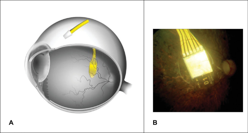
One in 4000 of the world population suffers from retinitis pigmentosa (RP), a major cause of visual disability and blindness in middle-aged people.1 Initially, the neuronal degeneration is limited to the first neuron of the visual system (the photoreceptor), whereas many of the second neurons (bipolar cells) and third neurons (ganglion cells) still operate for a long time during the course of disease.2 One way to partially restore visual function is the use of a subretinal prosthesis Alpha IMS (Retina Implant AG, Reutlingen Germany), which replaces the function of photoreceptors (Fig. 1).3–5
Figure 1.
(A) Schematic position of the subretinal retinal prosthesis Alpha IMS in the eye and the ceramic connection plate (to an introrbital silicon cable) on the sclera. (B) Fundus image showing the chip implanted beneath the retina.
The implant is driven by a battery and electronic control elements in a handheld unit, with a wireless transdermal connection by a retroauricular coil system.3,6 This system provides power and enables the patient to adjust sensitivity and contrast settings of the system via electromagnetic induction.5
Given two to three saccadic eye movements per second with additional microscopic, fixational eye movements in between, the intraorbital parts of the implant's power supply cables, which connect the subretinal implant to the retroauricular coil, are exposed to considerable mechanical stress.7,8 As patients blind from RP are comparably young and have a long lifespan ahead, durability and suitability of implant parts are essential.1 Hafed et al. demonstrated in postoperative eye tracking experiments in patients with Retina Implant Alpha, who regained vision allowing localization of objects, that eye movements for gaze can recover.9
Therefore, minimizing cable movement and, simultaneously, mechanical stress to the cable and the surrounding tissue is crucial, especially as cable breaks during initial phase of trials with Alpha IMS were common3. Such cable problems were solved in the subsequent model, the Retina Implant Alpha AMS,10 after extensive preclinical testing, outlined in the discussion section.
There are various implants that avoid orbital cables, for example, the PRIMA device11; instead of intraocular electronic amplifiers relatively bulky electronic goggles for amplification of image intensity need to be employed. Such goggles, however, reduce the utilization of natural gaze for object detection; not the case for patients after having received Retina Implant Alpha devices.9
The present study focuses on patients with the Retina Implant Alpha IMS and compares the variation in bending radius of the intraorbital cable during eye movements in three different routing techniques (straight cable route (A), parabulbar loop (B), and encircling band (C)) in the extreme positions.
Materials and Methods
Subjects
Nine patients (four females, five males), mean age ± standard deviation (SD) = 46.9 ± 7.2 years (age range 35–62 years) received the subretinal implant Alpha IMS (Retina Implant, Reutlingen, Germany) in the first single center part (2010–2011) of a multicenter trial (www.clinicaltrials.gov, NCT01024803). Prior to surgery, visual function was severely reduced due to legal blindness (eight patients: light perception without correct light source localization; one patient: no light perception) due to either RP (eight patients) or cone-rod dystrophy (one patient). None of the patients had additional eye disorders affecting the ascending optic pathways. Prior to study participation, all participants gave written informed consent in conformity with the Declaration of Helsinki. The local ethics committee approved the study, and it was performed in accordance with the German Medicinal Product Law (MPG) and EN ISO 14155.12
Electronic Retinal Implant (“Retina Chip”)
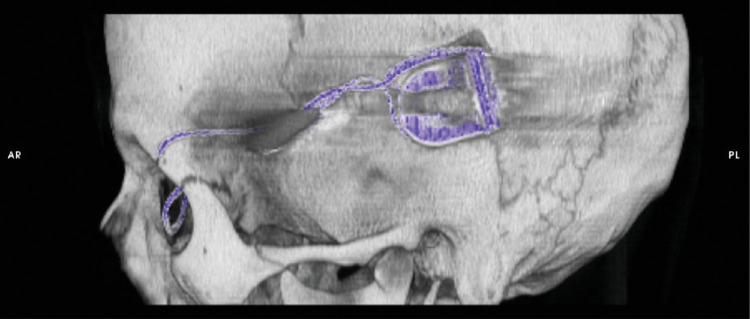
An integral part of the electronic retinal implant is a complementary metal–oxide–semiconductor (CMOS) chip, which has approximately 1500 pixels.5 Each pixel contains a photosensitive diode, an amplifier, and a stimulation electrode. The CMOS chip is mounted and connected to a flexible polyimide foil (intraocular part) that is connected to a silicon cable (extraocular part) via a ceramic adapter plate fixated on the sclera (Fig. 1). The silicon cable connects the chip via the adapter plate to the power supply in a special ceramic box compartment, which is further connected to a subdermal reference electrode behind the ear. This ceramic box compartment contains various electronic parts and a magnetic coil receiver for wireless power transfer through the skin (Figs. 1 and 2). This system is implanted completely subdermally.13 The power from an external battery compartment is transmitted wirelessly through the skin using two inductive/magnetic coils, one in the ceramic box compartment and one external coil kept in place by a magnet.6
Figure 2.
Computer tomographic reconstruction of the retroauricular position of the ceramic box, containing the coil and the electronics that enable to transmit energy and to control the implant's stimulation parameters, and the silicon cable running from the box to the orbit (Subject RIAG TU07).
Implantation/Surgical Procedure
The electronic subretinal implant was implanted as described previously.13,14 In brief, the tip of the polyimide foil containing the CMOS chip with the actual photosensitive pixels was implanted into the subretinal space, preferably under the fovea at the posterior pole of the eye (Fig. 1).15 The polyimide foil with the chip on its tip was inserted into the subretinal space toward the fovea from a superior lateral scleral incision near the equator of the eye (Fig. 1).15 The ceramic adapter plate that uses six gold wires to attach the polymide foil to the round silicon cable was sutured to the sclera.16,17 From this first fixation point on the moving eyeball, the silicon cable was running to another fixation point at the orbital rim of the upper temporal orbit (Fig. 3). The silicon cable then runs subperiostally from the orbital rim to the retroauricularly implanted ceramic box compartment (Fig. 2).6
Figure 3.
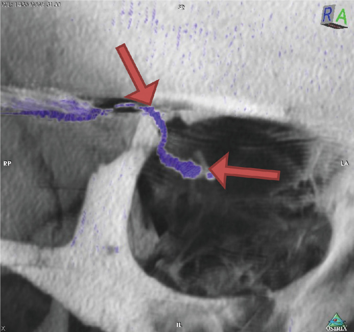
Arrows indicate the straight cable route between the two fixation points of the silicon cable, one at the orbital rim and the other at the fixation pad of the implant. The majority cable movements during eye movement and therefore the maximal mechanical stress acting on the cable occurs there (Subject RIAG TU02).
Between the two fixation points in the orbit, the silicon cable must follow the eye movements, while providing a stable electrical connection between the intraocular implant and the power supply system in the retroauricular ceramic box compartment. This is accomplished using one of the following three different routing techniques (Fig. 4)12:
Method A: The silicon cable runs straight on a direct short route from the orbital rim to the eyeball with only enough cable length to allow for limited eye movement, mainly in central viewing direction (maximum elongation of the silicon cable,Fig. 4A).
Method B: The silicon cable forms a parabulbar loop, thus distributing the movement onto a longer cable segment (Fig. 4B).
Method C: The silicon cable forms a loop around the eyeball (similar to scleral buckle surgery, which is used for retinal detachments) to reduce transmission of mechanical forces onto the intraocular parts of the implant (Fig. 4C).
Figure 4.
The three different surgical techniques for intraorbital cable routing: (A) straight route (Subject RIAG TU02), (B) parabulbar loop (Subject RIAG TU09), and (C) encircling band (Subject RIAG TU10). (from 12).
CT Imaging Technique
Video fluoroscopy (7.5 p/s; 55 nGy/p) was performed with a biplane angiography unit Axiom Artis zee (Siemens Healthcare, Erlangen, Germany) in three of nine patients (one patient per surgical method A, B, and C, respectively; 55–65 mGy per patient) to verify the assumption that the majority of the cable movement and therefore bending of the cable happened between the orbital rim and the eyeball, and that the other parts/sections of the silicon cable remain static during eye movement (Videos S1–S6 in supplementary material).12,18
All nine patients underwent computer tomography examinations (16 × 0.75, 130 mAs, Pitch 0.55; 120 kV) with a Somatom Sensation 16 multislice computer tomograph (Siemens Healthcare, Erlangen, Germany). An individual CT scan of the orbital region was performed for each of four viewing directions, a total of four scans per patient. CTDI (computed tomography dose index) was <25 mGy per scan, totaling <100 mGy per patient. No contrast agent was used.12,18
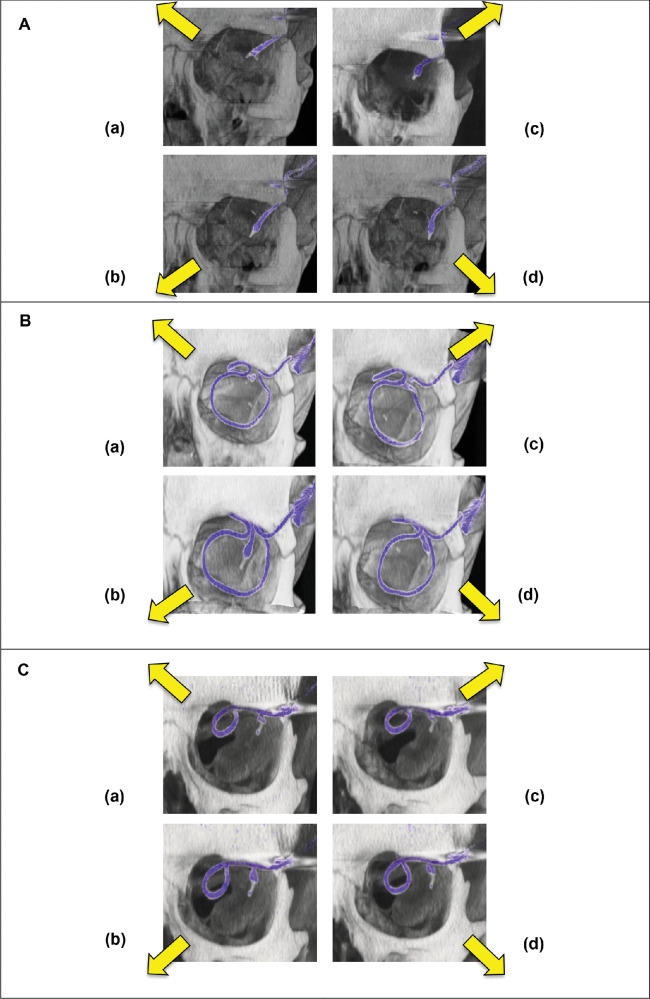
The four gaze directions were the following: upper temporal, upper nasal, lower temporal, and lower nasal gaze direction (Fig. 5). Diagonal gaze directions were chosen to exploit maximum extension as well as maximum bending radius of the cable running diagonally from the upper temporal orbital rim to the eyeball.12,18
Figure 5.
Cable position during eye movement for (A) straight route (method A, Subject RIAG TU05) and (B) encircling band (method C, Subject RIAG TU07), (C) parabulbar loop (method B, Subject RIAG TU12) four diagonal viewing directions each: (a) nasal superior (b) nasal inferior (c) temporal superior, and (d) temporal inferior.
Determination of Cable Bending Radius
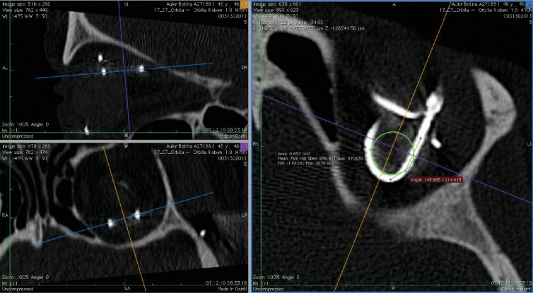
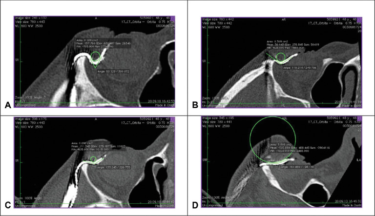
Datasets of each scan were analyzed in the 3D multiplanar reconstruction mode with the free DICOM viewer Osirix v4.1.2 (Pixmeo SARL, Bernex, Switzerland). One viewing plane was aligned precisely to the plane of the silicon cable route to avoid projection errors during measurement. The Circle ROI Tool (Oval ROI Tool while holding shift key) was aligned to the apex of the cable curve, showing the area of the circle ROI (Figs. 6 and 7). The radius of the circle outline was calculated via the formula:12,18
Figure 6.
Multiplanar reconstructions of computer tomography datasets. The viewing plane is aligned to the cable route (upper and lower left windows) to avoid projection errors for measuring the bending radius (right window, green circle, Subject RIAG TU07).
Figure 7.
Exemplary measurement of the bending radius in the four viewing directions in one participant with straight cable route (Subject RIAG TU05): (A) temporal superior (B) nasal superior (C) temporal inferior (D) nasal inferior. (Fig. 7 A from 18).
Mean and standard deviation (SD) of the bending radius was calculated for each subject. In particular, the determination of SD of the bending radius is important to estimate the mechanical stress on the cable: Minimal change of bending radius during eye movements causes minimal stress, whereas huge changes cause maximal stress, regardless of the mean bending radius in a moving eye.12,18
We performed repeated measurement analysis of variance (rmANOVA) to compare the three different routing techniques with the within-subject factor viewing direction (four levels: upper temporal, upper nasal, lower temporal, and lower nasal) and the between-subject factor operation method (three levels: method A (straight), method B (parabulbar loop), and method C (encircling band)). In case of significance, we used paired and two-sample t-test for further analysis.12,18
Operating Times
We compared the operating times for the three different surgical methods using analysis of variance (ANOVA) with the inner-subject factor operation method (three levels: method A (straight), method B (parabulbar loop), and method C (encircling band)).
Statistical Analysis
IBM SPSS Statistics 25.0 (International Business Machines Corporation, Armonk, NY, USA) was used. Whenever the Shapiro-Wilk test indicated a deviation from normal, we used logharitmized data. Whenever Mauchly's Test of Sphericity was violated, we used the Greenhouse-Geisser correction. A P-value of < 0.05 was regarded as statistically significant. The Bonferroni correction was used to correct for multiple comparison.
Results
Optimal Bending Radius
Average bending radius ± SD was 5.9 ± 4.8 mm for method A (n = 3 patients), 2.5 ± 0.4 mm for method B (n = 3), and 4.1 ± 0.7 mm (n = 3) for method C. Based on this calculation, average bending radius variation was 87% for method A, 11% for method B, and 16% for method C (Table 1).
Table 1.
Individual Bending Radius
| Method A (Straight Route) | Method B (Parabulbar Loop) | Method C (Encircling Band) | |||||||
|---|---|---|---|---|---|---|---|---|---|
| Bending Radius (mm) | Sub 2 | Sub 6 | Sub 5 | Sub 9 | Sub 12 | Sub 1 | Sub 7 | Sub 8 | Sub 10 |
| Upper temporal (mm) | 2.3 | 0.6 | 1.4 | 2.7 | 1.9 | 2.5 | 5.1 | 3.9 | 5.5 |
| Upper nasal (mm) | 3 | 9 | 6.8 | 2.7 | 1.8 | 2.2 | 4 | 3.7 | 4.2 |
| Lower temporal (mm) | 3.1 | 2.1 | 5.9 | 3.1 | 2.3 | 2.2 | 4.7 | 3.1 | 3.9 |
| Lower nasal (mm) | 16.6 | 9.2 | 11 | 3.1 | 2.4 | 2.7 | 3.6 | 4.4 | 3.6 |
| Mean ± SD (mm) | 6.3 ± 6.9 | 5.2 ± 4.5 | 6.3 ± 3.9 | 2.9 ± 0.2 | 2.1 ± 0.3 | 2.4 ± 0.2 | 4.4 ± 0.7 | 3.8 ± 0.5 | 4.3 ± 0.8 |
| Standard Deviation (%) | 111 | 86 | 63 | 8 | 14 | 10 | 16 | 14 | 19 |
| Mean variation of bending radius (%) | 86.7 ± 24.0 | 10.7 ± 3.1 | 16.3 ± 2.5 | ||||||
Table displays the individual bending radius in mm for nine subjects in three different surgical techniques (A, B, and C) in four viewing directions (upper temporal, upper nasal, lower temporal, lower nasal) and the mean bending radius for each subject as well as the standard deviation. The variation of bending radius for each method is calculated. Percentages indicate the standard deviation relative to the mean for each subject. The change in bending radius for each method is calculated from the mean of percent standard deviation for the three participants, who were operated with the corresponding method.
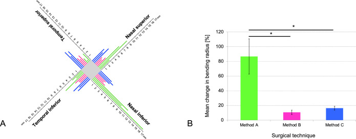
Individual bending radius change was maximal for method A: It ranged from 16.6 mm in the nasal inferior direction to 2.3 mm in the temporal superior direction in subject 2. The percent standard deviation of the mean bending radius was 111% in this participant. In contrast, the percent standard deviation of the mean bending radius was minimal in subject 9 (8% of mean bending radius), who underwent the method B procedure. The mean change in bending radius of all subjects was maximal for method A (mean ± SD = 86.7 ± 24.0%), mediocre for method C (mean ± SD = 16.3 ± 2.5%), and minimal for method B (mean ± SD = 10.7 ± 3.1%) (Fig. 8).
Figure 8.
Individual bending radius in four viewing directions. (A) Chart illustrates the individual bending radius in mm for nine subjects in the four viewing directions: temporal superior, temporal inferior, nasal superior, and nasal inferior. Green lines indicate patients with method A operation (straight route), pink lines indicate patients with method B operation (parabulbar loop), and blue lines indicate patients with method C operation (encircling band). While bending radius for methods B and C was similar in the four viewing directions, patients with method A showed an increased bending radius in the nasal directions. With a straight route (method A) bending radius varied strongly between the viewing directions. (B) Bar chart displaying the mean variation ± standard deviation of the mean in bending radius (%) for the three surgical techniques: Method A (straight route), method B (parabulbar loop), and method C (encircling band). Each method was evaluated in three subjects and four viewing directions (temporal superior, temporal inferior, nasal superior, and nasal inferior). Asterisks indicate significant differences (P < 0.017).
RmANOVA revealed a significant effect of viewing direction (P = 0.002, F(3,18) = 7.225), a significant effect of the viewing direction × operation method interaction (P = 0.000, F(6) = 8.399). The between-subject factor operation method was significant (P = 0.013, F(2,6) = 9.606).
One-way ANOVA revealed a significant difference in percent change of standard deviation between the three different methods (P = 0.000, F(2, 6) = 59.848). Average cable movement differed significantly between method A and B (t(4) = 9.078, P = 0.001) and between method A and C (t(4) = 8.868, P = 0.001). There was no significant difference between method B and C (t(4) = –2.404, P = 0.074).
Operating Times
Operating times did not vary significantly between the three surgical methods (P = 0.613, F(2,6) = 0.531) (Table 2).
Table 2.
Operating Times
| Method A (Straight Route) | Method B (Parabulbar Loop) | Method C (Encircling Band) | ||||
|---|---|---|---|---|---|---|
| Individual operating time | sub 2 | 480 min | sub 1 | 505 min | sub 7 | 485 min |
| sub 5 | 485 min | sub 9 | 595 min | sub 8 | 505 min | |
| sub 6 | 480 min | sub 12 | 480 min | sub 10 | 460 min | |
| Mean | 481.67 min | 493.33 min | 483.33 min | |||
| Standard deviation | 2.89 min | 12.58 min | 22.55 min | |||
Table displays the individual and mean operating times for nine subjects in the three different surgical techniques:method A (straight route), method B (parabulbar loop), and method C (encircling band).
Discussion
This study applied computer tomography to determine the cable routing technique for subretinal implants that provides minimal bending of extraocular cables and, hence, might produce minimal mechanical stress due to eye movements in vivo. Reduction of mechanical stress is crucial for long-term function and reliability for daily use of these devices.
We compared the amount of bending radius variation in three different surgical techniques. Method B (parabulbar loop) and method C (encircling band) showed comparable changes in bending radius and might consequently cause similar mechanical cable stress during eye movements (Fig. 8). Both methods showed significantly less cable movement than method A (straight route,Table 1, Fig. 8). Overall, our study demonstrated that both a parabulbar loop (method B) and the more complex encircling band (method C) showed minimal variation in bending radius and might reduce cable stress in subretinal electronical implants due to eye movements.12 Mean operation time was comparable for all methods (Table 2). The whole procedure (intra- and extraorbital surgery) takes about eight hours. However, interindividual variability of surgery time was bigger for methods B and C compared to method A (Table 2), which reflects the higher complexity of the surgical procedures.
The presented method for analysis of implanted cables is not only applicable to subretinal implants, but to any cable structure, exposed to movement within the human body, for example, cerebral shunts used for hydrocephaly treatment or limb protheses.19–22 Assessment only requires standard CT devices and any DICOM viewer capable of freely adjustable viewing planes and basic measurement tools.
Compared to other organs, the high mobility and permanent intentional and unintentional position changes of the eye exposes cables to severe mechanical stress and can cause changes in microchip position.7,23 In performing CT-imaging, this study revealed that the variation of bending radius between different eye movements can be considerably minimized by optimizing bended cable routings. Kuehlewein et al. had analyzed the change of chip position in patients with subretinal implant Alpha IMS and AMS, including the cohort of this paper, in vivo. All our patients with straight cable route and parabulbar loop had stable or minor variations of chip position. In contrast, two patients with encircling band had significant changes in chip position and in the third patient the retinal implant had to be repositioned after 48 days due to a retinal hole at the distant border of the chip.23
Cable bending and the optimal course for the orbital cable portion had been investigated in human cadaver head studies with mock surgeries in the anatomy department (K.U. Bartz-Schmidt and F. Gekeler, Tübingen, personal communication) before any clinical application. However, the individual orbital situation of patients in the first clinical trial with the Retina Implant Alpha IMS had required personalized adaptation of the initial cable procedure during the trial and resulted in the various loop sizes described here. Subsequently, Daschner et al. had recorded clinical reliability data in a laboratory set up for advanced aging experiments.10 The power supply cable was tested using machine that simulated the movements of the eye by bending the fixated cable over 27 million times. CT images had been used to optimize the apparatus,24 rendering application of cable bound implants safe.
Indeed, real-life data confirmed that the use of the surgical technique of a parabulbar loop (method B) and material improvements of the cable could eliminate cable breaks in the subretinal implant Alpha IMS and its successor Alpha AMS.3,4 Furthermore, in vivo data revealed that this surgical technique only leads to minor changes in chip position.23 Additional technical improvements in design and manufacturing of the intraorbital cable used in Alpha AMS even prolonged the mean lifetime of the subretinal implant to seven years (compared to 1.5 years in Alpha IMS).10
Consequently, bended cable routings can reduce the mechanical stress on the cable and surrounding tissue and might prolong the implant's lifetime. This finding is important as subretinal implant patients generally are young and have a long life ahead.1,3,5
Supplementary Material
Acknowledgments
The authors thank I. Stingl for the graphic implementation. The trial was sponsored by Retina Implant AG, Reutlingen, Germany, which participated in the study design and supplied the technical assistance of clinical engineers during tests. This study is part of the research program of the Bernstein Center for Computational Neuroscience, Tuebingen, Germany, funded by the German Federal Ministry of Education and Research (BMBF; FKZ: 01GQ1002).
Supported by the German Research Foundation (DFG): SFB1233, Robust Vision: Inference Principles and Neural Mechanisms, TP14 (Project number 276693517).
Disclosure: H. Faber, None; U. Ernemann, None; H. Sachs, None; F . Gekeler, Retina Implant AG i.L. (C); S. Danz, None; A. Koitschev, None; D. Besch, None; K.-U. Bartz-Schmidt, Retina Implant AG i.L., RICE (F, I); E. Zrenner, Retina Implant AG i.L. (C, P, R, S); K. Stingl, None; C. Kernstock, None
Supplementary Material
Videos for method A (Video S1 & S2) and method B (Video S3 & S4).
Supplementary Video S1. Straight route viewed from the bottom left (Subject TU_05).
Supplementary Video S2. Straight route viewed from the front (Subject TU_05).
Supplementary Video S3. Encircling band viewed from the bottom left (Subject TU_07).
Supplementary Video S4. Encircling band viewed from the front (Subject TU_07).
Supplementary Video S5. Parabulbar loop viewed from the bottom left (Subject TU_12).
Supplementary Video S6. Parabulbar loop viewed from the front (Subject TU_12).
References
- 1. Verbakel SK, van Huet RAC, Boon CJF, et al.. Non-syndromic retinitis pigmentosa. Prog Retin Eye Res. 2018; 66: 157–186, 10.1016/j.preteyeres.2018.03.005. [DOI] [PubMed] [Google Scholar]
- 2. Santos A, Humayun MS, de Juan E, et al.. Preservation of the inner retina in retinitis pigmentosa: a morphometric analysis. Arch Ophthalmol. 1997; 115(4): 511–515, 10.1001/archopht.1997.01100150513011. [DOI] [PubMed] [Google Scholar]
- 3. Stingl K, Bartz-Schmidt KU, Besch D, et al.. Subretinal visual implant Alpha IMS – clinical trial interim report. Vision Res. 2015; 111: 149–160, 10.1016/j.visres.2015.03.001. [DOI] [PubMed] [Google Scholar]
- 4. Stingl K, Schippert R, Bartz-Schmidt KU, et al.. Interim results of a multicenter trial with the new electronic subretinal implant Alpha AMS in 15 patients blind from inherited retinal degenerations. Front Neurosci. 2017; 11, 10.3389/fnins.2017.00445. [DOI] [PMC free article] [PubMed] [Google Scholar]
- 5. Zrenner E, Bartz-Schmidt KU, Benav H, et al.. Subretinal electronic chips allow blind patients to read letters and combine them to words. Proc Biol Sci. 2011; 278(1711): 1489–1497, 10.1098/rspb.2010.1747. [DOI] [PMC free article] [PubMed] [Google Scholar]
- 6. Koitschev A, Stingl K, Bartz-Schmidt KU, et al.. Extraocular surgical approach for placement of subretinal implants in blind patients: lessons from cochlear-implants. J Ophthalmol. 2015; 2015, 10.1155/2015/842518. [DOI] [PMC free article] [PubMed] [Google Scholar]
- 7. Rucci M, Poletti M.. Control and functions of fixational eye movements. Annu Rev Vis Sci. 2015; 1: 499–518, 10.1146/annurev-vision-082114-035742. [DOI] [PMC free article] [PubMed] [Google Scholar]
- 8. Rucci M, Victor JD.. The unsteady eye: an information-processing stage, not a bug. Trends Neurosci. 2015; 38(4): 195–206, 10.1016/j.tins.2015.01.005. [DOI] [PMC free article] [PubMed] [Google Scholar]
- 9. Hafed ZM, Stingl K, Bartz-Schmidt K-U, Gekeler F, Zrenner E.. Oculomotor behavior of blind patients seeing with a subretinal visual implant. Vision Res. 2016; 118: 119–131, 10.1016/j.visres.2015.04.006. [DOI] [PubMed] [Google Scholar]
- 10. Daschner R, Greppmaier U, Kokelmann M, et al.. Laboratory and clinical reliability of conformally coated subretinal implants. Biomed Microdevices. 2017; 19(1): 7, 10.1007/s10544-017-0147-6. [DOI] [PMC free article] [PubMed] [Google Scholar]
- 11. Palanker D, Mer YL, Mohand-Said S, Muqit M, Sahel JA.. Photovoltaic restoration of central vision in atrophic age-related macular degeneration. Ophthalmology. 2020; 127(8): 1097–1104, 10.1016/j.ophtha.2020.02.024. [DOI] [PMC free article] [PubMed] [Google Scholar]
- 12. Kernstock CJ, IOVS; 2012,53, ARVO E-Abstract, 5514 [Google Scholar]
- 13. Besch D, Sachs H, Szurman P, et al.. Extraocular surgery for implantation of an active subretinal visual prosthesis with external connections: feasibility and outcome in seven patients. Br J Ophthalmol. 2008; 92(10): 1361, 10.1136/bjo.2007.131961. [DOI] [PubMed] [Google Scholar]
- 14. Sachs HG, Bartz-Schmidt K-U, Gabel V-P, Zrenner E, Gekeler F.. Subretinal implant: the intraocular implantation technique. Nova Acta Leopoldina NF III. 2011; 379: 217–223. [Google Scholar]
- 15. Stingl K, Bartz-Schmidt K-U, Gekeler F, Kusnyerik A, Sachs H, Zrenner E.. Functional outcome in subretinal electronic implants depends on foveal eccentricity. Invest Ophthalmol Vis Sci. 2013; 54(12): 7658–7665, 10.1167/iovs.13-12835. [DOI] [PubMed] [Google Scholar]
- 16. Gekeler F, Szurmann P, Besch D, et al.. Implantation and explantation of active subretinal visual prostheses using a combined transcutaneous and transchoroidal approach. Nova Acta Leopoldina NF 111. 2010; 379: 205–216. [Google Scholar]
- 17. Gekeler K, Bartz-Schmidt KU, Sachs H, et al.. Implantation, removal and replacement of subretinal electronic implants for restoration of vision in patients with retinitis pigmentosa. Curr Opin Ophthalmol. 2018; 29(3): 239, 10.1097/ICU.0000000000000467. [DOI] [PubMed] [Google Scholar]
- 18. Kernstock CJ, IOVS; 2011, 52, ARVO E-Abstract, 1341. [Google Scholar]
- 19. Ezzat AAM, Soliman MAR, Hasanain AA, et al.. Migration of the distal catheter of ventriculoperitoneal shunts in pediatric age group: case series. World Neurosurg. 2018; 119: e131–e137, 10.1016/j.wneu.2018.07.073. [DOI] [PubMed] [Google Scholar]
- 20. Oddo CM, Raspopovic S, Artoni F, et al.. Intraneural stimulation elicits discrimination of textural features by artificial fingertip in intact and amputee humans. Elife. 2016; 5: e09148, 10.7554/eLife.09148. [DOI] [PMC free article] [PubMed] [Google Scholar]
- 21. Raspopovic S, Capogrosso M, Petrini FM, et al.. Restoring natural sensory feedback in real-time bidirectional hand prostheses. Sci Transl Med. 2014; 6(222): 222ra19–222ra19, 10.1126/scitranslmed.3006820. [DOI] [PubMed] [Google Scholar]
- 22. Reddy GK. Ventriculoperitoneal shunt surgery and the incidence of shunt revision in adult patients with hemorrhage-related hydrocephalus. Clin Neurol Neurosurg. 2012; 114(9): 1211–1216, 10.1016/j.clineuro.2012.02.050. [DOI] [PubMed] [Google Scholar]
- 23. Kuehlewein L, Troelenberg N, Stingl K, et al.. Changes in microchip position after implantation of a subretinal vision prosthesis in humans. Acta Ophthalmol (Copenh). 2019; 97(6): e871–e876, 10.1111/aos.14077. [DOI] [PubMed] [Google Scholar]
- 24. Kokelmann M, Wrobel W-G.. Mechanical alternating loads in neuroprosthetics: the example of subretinal implants. Biomed Tech (Berl). 2012; 57(SI-1-Track-S): 102, 10.1515/bmt-2012-4040. [DOI] [Google Scholar]
Associated Data
This section collects any data citations, data availability statements, or supplementary materials included in this article.


