

Abstract
Additive manufacturing (AM), or 3D printing, of bioceramic scaffolds promises personalized treatment options for patients with site-specific designability for repair and reconstruction of bone defects. Although the theory for creating these complex geometries has already been made possible through AM’s advancement, such shapes’ manufacturability is difficult due to printing with ceramics’ inherent complexities. Ceramics have the added challenge of being highly brittle, poor handleability of green (pre-sintered) parts, making complex shape high strength parts challenging to manufacture. This has led to a significant literature gap regarding the feasibility of creating bioceramic scaffolds with unique architectures that can be used in site-specific, individualized patient treatment. This work aims to successfully create complex topographical surfaces of cylindrical bone-like scaffolds to understand the correlation of increasing the scaffold surface area on mechanical properties and in vitro osteoblast cell proliferation. An increase in osteoblast cell proliferation and facilitation in cellular attachment can ultimately lead to improved bone healing. This work explores the printing parameters within an Innovent+® ExOne binder jet 3D printer to produce scaffold designs from synthesized tricalcium phosphate powder. Mechanical testing reveals the designed structures enhance scaffold compressive strength by 30% compared to control dense cylindrical scaffolds. Osteoblast cell proliferation is also increased due to changes in surface topography with a nearly 2-fold increase. Our work incorporates macro-level topographical changes to increase surface area, which is another avenue that could be combined with other scaffold features such as porosity. Results show bulk surface topography modifications via 3D printing can increase surface area to support enhanced biological response without compromising mechanical properties. This discovery may enable a future generation of porous scaffolds with external structures for further progress towards proper defect-specific synthetic bone grafts.
Keywords: bioceramic, additive manufacturing, binder jet, tricalcium phosphate, bone defect
Graphical Abstract

1. Introduction
Bone is a complex, continually remodeling organ with various purposes including protecting other organs, producing red and white blood cells, and providing structural support for the body. The bone architecture is random with an elaborate interconnected, porous structure to allow for the transport of nutrients and cellular ingrowth. The porous nature of bone also houses blood vessels, veins, and nerves. Due to the necessity of bone for mobility, any bone defect will significantly impact those affected’ daily lives. Defects can be congenital, caused by trauma or surgery complications, tumor resection, or infection [1].
Bone remodeling is when old bone is removed via osteoclast cells, and new bone formation is made through osteoblast cells. A mismatch causes bone disorders like osteoporosis and osteopenia, induced by osteoclast resorption to a new bone formation where resorption occurs more rapidly and causes lower bone density. Disorders such as these, and tumor resection to combat bone cancers, can leave large voids in bone, necessitating bone grafts. Various bone grafting methods, including autografts, allografts, and xenografts, fill in these voids that are critically too large for self-healing. Porous scaffolds, made from materials that mimic the natural bone chemistry like hydroxyapatite (HA) and tricalcium phosphate (TCP), can aid in replacing standard grafting applications by removing the need for a donor [2–4]. Manufacturing scaffolds with additive manufacturing (AM) enable complex defect shapes that can be customizable per patient’s need. Although complex shaping ability via additive manufacturing or 3D printing (3DP) is well-known, current bone graft research focuses mainly on creating different types of porosities as the available avenue for macro-level surface area enhancement for cellular attachment and tissue ingrowth [5–8]. Our work investigates the addition of different protruded bulk surface features instead of porosities to increase the surface area to volume ratio of scaffolds to enhance biological fixation without compromising the mechanical strength. Bone defects can be complicated with non-uniform sizes and bring about the need for intricate topography. There is a current lack in the literature that addresses the feasibility of creating bioceramic scaffolds with unique macro-level architectures that can address site-specificity for individual patient treatment. It is vital to understand how these external features will affect mechanical properties and stability, along with the biological efficacy in vitro.
Calcium phosphate cylindrical scaffolds are standard in the literature, as outlined by ASTM standards F2883–11 and C1424–15. Previous methods to create scaffolds include solid and porous cylindrical constructs using HA and calcium sulfate with binder jet-based 3D Printing [5]. Another study focused on creating porous cylindrical scaffolds with inner architecture to make the depowderizing process easier post 3D Printing [6]. A unique flexible 3D printer created cylindrical scaffolds made of HA [7]. While these scaffolds were innovative in the printing process, they do not show complex external features to the base cylinders [9–11]. Additionally, a scaffold with complex external surfaces and unique topography will increase the basic scaffold’s outer macro-level surface area. The surface area plays a vital role in cellular attachment, as it provides anchoring areas that cells can expand and extend [12,13].
Authors hypothesize with the addition of bulk protruded topographical features, an increase in the macro-level surface area can support osteoblast proliferation for bone grafting applications. Although the surface area is enhanced using pores, the voids often compromise the mechanical integrity and strength. This work focuses on exploring another avenue for increasing scaffold surface area within the AM design and fabrication parameters to enhance bone tissue-implant anchoring ability without compromising mechanical strengths. This work aims to understand the effects of external surface area on bone tissue engineering scaffolds. The objectives to achieve this aim are (1) to measure the effects on mechanical properties and (2) to understand osteoblast (bone-forming) cell proliferation to assess the effects on biological properties. The surface area is altered in this study via intricate topographical designs, including vertical ridges, horizontal ridges in the form of a corkscrew, and cylindrical bumps. The volume amongst all of these designed scaffolds is maintained similarly to compare with the control. Our group has explored 3D printed porous TCP cylindrical scaffolds but have yet to explore complex topography and architecture to increase surface area [14–17]. These newly designed scaffolds are manufactured, tested for mechanical properties using compressive strength testing, imaged using scanning electron microscopy (SEM), and assessed in vitro using human fetal osteoblast cells. This work hopes to provide the scientific community with more knowledge on the feasibility of creating complex geometries on calcium phosphate scaffolds for the individualized patient and site-specific bone defect repair.
2. Materials and methods
2.1. Synthesized β-TCP powder preparation and characterization
A synthesizing process with dicalcium phosphate (calcium phosphate dibasic, CaHPO4, 98.0–105.0%) and calcium carbonate (CaCO3, ≥99.0%) (Sigma-Aldrich, St. Louis, MO) was utilized to make β-TCP powder shown in Fig. 1 [18]. A 2:1 mole ratio was maintained between CaHPO4 and CaCO3 followed by ball mixing for 2 h at 70 rpm. Zirconia ball milling media to powder weight ratio was 2:1. The mixed powder was then calcined for 24 h at 1050°C in a furnace. Post calcination, the powder was wet-milled using 1.5x w/v of ethanol and 2x w/w of milling media to powder for 2 h at 70 rpm. Ethanol is used to break up aggregates to decrease the particle size while not dissolving the TCP into solution as water would [19,20]. Ethanol was evaporated, and the dried powder was then washed with deionized water to remove any salts. The powder was once again dried at 250°C for 2 h prior to printing to remove any chemisorbed moisture.
Fig. 1.

The synthesis of β-TCP powder starting with dicalcium phosphate and calcium carbonate precursor powders.
Characterization of the powder pre- and post- scaffold processing includes X-ray diffraction (XRD) and Fourier Transform Infrared Spectroscopy (FTIR). For XRD analysis, a PANalytical X’Pert Pro MPD X-ray diffractometer with a Cu Kα radiation was employed. Other parameters include 45 eV and 40 mA at room temperature with a Ni-filter, 2-theta range of 20 to 50 degrees with a step size of 0.05, and 10 s dwell. For FTIR analysis, an Attenuated Total Reflection FTIR spectrophotometer (Nicolet 6700, ThermoFisher, Madison, WI) in the 400–4000 cm−1 wave number range was employed.
2.2. Scaffold design, 3D printing process, and scaffold’s mechanical properties
Four scaffold designs were manufactured using the Innovent+® ExOne binder jet 3D printer: control, ridges, corkscrew, and bumps. Scaffolds were designed in SolidWorks with a cylindrical base, with approximate dimensions of 7 mm diameter x 11 mm height. The scaffold designs’ volumes are kept within a ± 0.5% variance, but with increased surface areas than the control cylinders with no exterior designs. Since contact surface area plays a critical role in compressive strength testing, the contact surface area’s dimensions and core scaffold diameter are maintained within volume constraints. A compressive strength simulation with Finite Element Analysis (FEA) was performed in SolidWorks to initially test the relative mechanical compressive strength viability to ensure designed scaffolds would be comparable to control before manufacturing. The simulation parameters include a fixed geometry on the bottom base surface followed by a 200 N vertical force placed on the top surface. A standard mesh was applied to all, and full mesh information can be found in Fig. S1. The material property was set to ‘ceramic porcelain’, the only readily available ceramic material for selection. It should be reiterated that the strength comparison in this simulation is entirely relative to control; therefore the material does not have to match true TCP, but a proof of concept for the introduced scaffold designs was achievable. For a simple comparison, the density of this ceramic porcelain material is 2.3 g cm −3, and the density of TCP is 3.14 g cm −3.
After the designs proved comparable to control in simulated compressive strength, the scaffolds were physically built layer-by-layer with TCP powder and a commercially available organic binder purchased from the company (ExOne). It should be noted the printing build bed was organized in such a way that all scaffolds would be built in the same Z-plane; however, the distribution of designs was randomized within the X-Y grid to ensure build bed printing variability. These factors for the internal validity of scaffold manufacturability in future testing.
The Innovent+® is equipped with a powder hopper, unlike traditional power bed 3D printers. This hopper system allows for only a build bed without the need for a separate feedstock bed. Layers of TCP are deposited by the recoater, which traverses over the build bed, deposits TCP, and follows with a roller to smooth the layer. Parametric values for these print conditions can be found in Table 1. The inkjet printhead travels perpendicular to the build bed to deposit binder droplets for the printed layer. Binder saturation, drop volume, and other printhead/binder jet settings can be found in Table 2. Once the print job has been completed, the entire build bed is placed into an oven for 1.5 h at 175°C to cure the binder. Scaffolds are carefully removed from the build bed; the air is blown to clear excess powder and placed into a muffle furnace. Gradual heat steps are employed with a dwell at 120°C followed by 1 h at 600°C for binder removal. Sintering densification of the scaffolds was finally performed at 1250°C for 2 h. A schematic of the entire manufacturing process can be seen in Fig. 2. A screw-driven universal testing machine with a load cell of 50 kN (AG-IS, Shimadzu, Japan) was used for compressive strength measurements. A constant crosshead speed of 0.33 mm min−1 was employed during testing. Young’s modulus of control and treatment designs are found from the slope of the initial linear portion of the generated stress-strain curve from compression testing.
Table 1.
Parametric values for print conditions.
| Parameters | Value | Significance |
|---|---|---|
| Target Bed Temperature | 27–30 ºC | Goal temperature of build bed which is adjusted through the emitter lamp. |
| Binder Set Time | 2 sec | Amount of time to set binder before drying. |
| Drying Time | 10 sec | Amount of time set aside for drying between layers. |
| Emitter Output | 100% | The output of the emitter lamp during the drying cycle. |
| Recoat Speed | Varies | Speed of the recoater during powder deposition. |
| Ultrasonic Intensity | 100% | Strength of ultrasonic attached to the recoater. |
| Roller Traverse Speed | 5 mm/sec | Speed of the roller as it goes across the build bed. |
| Roller Rotation Speed | 300 rpm | Rate of rotation of the roller. |
Table 2.
Parametric values for the printhead and binder jetting.
| Parameters | Value | Significance |
|---|---|---|
| Desired Saturation | 90% | This value represents the theoretical void space that exists between powder particles that will be filled with binder |
| Drop Volume | 68.4 pL | Amount of binder per droplet. This must be calculated to achieve desired saturation. This is found via measurement. |
| Build Layer Thickness (Z layer spacing) | 50 μm | Build bed drops this distance between each layer followed by powder deposition. |
| X Jet Spacing | 254 μm | Distance between jets in the print head. |
| Y Print Speed | 150 mm/s | Printhead speed in the Y direction, which is calculated by Drop Spacing and Computed Drop Frequency. |
| Printhead Firing Frequency | 2505 Hz | Frequency of printhead firing binder jets. |
| Passes Per Jet Spacing | 4 | Number of necessary passes to print each layer. |
| X Drop Spacing | 63.5 μm | Distance between binder jets in the X direction. |
| Y Drop Spacing | 59.9 μm | Distance between binder jet deposition in the Y direction. |
Fig. 2.

Schematic representation of the printing process using the Innovent+® ExOne. Equipped with a powder hopper, the Innovent+® is different than other typical powder bed processing printers. Only one build bed is employed and powder is deposited ultrasonically from a traversing hopper. Once printing is complete, samples are cured, air blown to remove loose particles, gradually heated for binder burnout, and then sintered.
2.3. In vitro osteoblast culture
Human fetal osteoblast cells (hFOB 1.19, ATCC, Manassas, VA) were utilized to assess the scaffold designs’ biocompatibility and cell attachment. Scaffolds were sterilized before use in culture using an autoclave for 1 h at 121°C. Additional SEM micrographs were taken to compare before and after sterilization to ensure no changes occurred in the scaffold microstructure. The entire culture was performed in a sterilized hood to prevent contamination. Cells were cultured and incubated based on manufacturing specifications with a temperature of 34°C under an atmosphere of 5% CO2. Cell medium comprised of Ham’s F12 Medium and Dulbecco’s Modified Eagle’s Medium (DMEM/F12, Sigma, St. Louis, MO) in equal parts followed by 1.2 mg mL−1 of sodium bicarbonate (NaHCO3) and 0.3 mg/mL of G418 (Sigma Aldrich, St. Louis, MO), all within deionized water. The media was then supplemented with 10% fetal bovine serum (FBS, ATCC, Manassas, VA) followed by 0.1% penicillin-streptomycin. The cell medium was filter-sterilized within the hood before use. A cell density of 25,000 cells per sample was employed for the study.
2.4. Osteoblast cellular proliferation and morphology
Osteoblast proliferation and viability were determined using MTT (3-(4,5-dimethylthiazol-2-yl)-2,5-diphenyltetraxolium bromide) assay. At time points of 3, 7, and 11 days, each scaffold design’s biological triplicates were immersed in 900 μl of cell media and 100 μl of MTT (Sigma, St. Louis, MO) solution in a 24-well plate followed by incubation for 2 h at 34°C. Following incubation, the media/MTT solution was removed, and 600 μl of solubilizer, comprised of 10% Triton X-100, 0.1 N HCl, and isopropanol, was added to dissolve the formazan crystals produced during the MTT assay incubation. Technical triplicates for MTT assay solutions were utilized for each scaffold design using 100 μl moved to a 96-well plate and read in a Biotek Synergy 2 SLFPTAD microplate reader (Biotek, Winooski, VT, USA) at 570 nm.
Osteoblast cellular morphology was assessed, also at time points of 3, 7, and 11 days, using SEM imaging [21]. Before imaging, samples were removed from the culture, media removed, and immersed in fixative comprised of 2% paraformaldehyde and 2% glutaraldehyde in 0.1 M phosphate buffer. Samples were held overnight at 4°C, then rinsed with 0.1 M phosphate buffer and ultimately fixed using 2% osmium tetroxide for 2 h. Samples were then washed with 0.1 M phosphate buffer, deionized water (3x), an increasing ethanol series up to 100% (3x), and hexamethyldisilane (2x) [22]. A gold sputter coater was utilized to apply a coating approximately 10–15 nm thick. SEM imaging was performed on an FEI Quanta 200F SEM.
2.5. Statistical Analysis
For the compressive strength tests, six replicates (n=6); for each biological test, three biological/sample replicates (n=3) and three analytical replicates (n=3) were used. A one-way ANOVA with posthoc Tukey-Krammer analyses was performed.
3. Results and discussion
3.1. Scaffold properties and characterizations
The XRD and FTIR spectra can be seen in Fig.3(a,b). The XRD spectrum shows the β-TCP phase (ICDD: 98–009-7500) in pre- and post- processing powder. Post-processing also shows α-TCP phase (ICDD: 01–070-0364). The FTIR spectrum shows symmetric (v1), antisymmetric (v3) P—O stretching modes, and antisymmetric (v4) bending mode. The four scaffold designs with associated external surface areas normalized to their respective volumes can be seen in Fig. 3(c). The designs were kept volumetrically constant compared to the cylindrical control scaffold, but all have increasing external surface areas of varying architecture. The compressive strength simulation performed in SolidWorks can be seen in Fig. 3(d), illustrating an increase in relative compressive strength compared to control with an increase in maximum loading and much smaller minimum loading in the corkscrew and bumps scaffolds. The simulation aims to support the proof of concept that the complex architectures would not negatively affect the mechanical properties of control cylindrical scaffolds. The results support the viability of manufacturing these designed scaffolds. It is expected that the corkscrew and bumps scaffolds would have such low minimum stress points (blue) because these surfaces do not come into contact with either the downward or a normal upward force.
Fig. 3.

Scaffold design and material properties. a) X-ray diffraction spectra of synthesized TCP powder pre- and post- processing. Synthesized powder pre-processing shows characteristic peaks of β-TCP. Post-processed TCP powder still demonstrates characteristic peaks of β-TCP but also expresses α-TCP phase. This can occur due to the high temperature needed for sintering. b) Fourier Transform Infrared Spectroscopy (FTIR) spectra of synthesized TCP powder pre- and post- processing. Both spectra show characteristic functional phosphate groups of TCP. c) CAD designs with associated surface area normalized to volume is displayed, compared to control scaffold. For all three tested designs, the increased ratio difference is displayed. The surface area is the tested parameter change, and the volumes are kept constant within ± 0.5%. (d,e) SolidWorks compressive strength simulation of designed scaffolds compared to control. Symbols for the 200 N downward force and fixed geometry on the scaffold base are shown by a purple arrow and green arrows, respectively. Simulation images show maximum or ultimate strength in red and minimum or lowest stress points in blue. Maximum and minimum strength are reported as normalized percentages compared to control. All designed scaffolds pass the proof of concept phase to determine if the mechanical properties are comparable to control. The simulation illustrates an increase in mechanical properties with the designed scaffolds.
The printed, post-sintered scaffolds can be seen in Fig. 4(a), which showcases the successful printing of the complex scaffold structures. Also seen is an SEM micrograph of the sintered 3DP TCP scaffold surface microstructure. Although the scaffolds are printed without designed porosities, residual scaffold porosities remain at approximately 10 ± 5 %. In preparation for the cell culture, all samples are autoclaved for sterilization, and the SEM micrographs of the sample surface and microstructure can be seen in Fig. 4(b,c). No apparent differences are observed between control and treatment before and after sterilization, indicating stability and retention of the original scaffold composition before the osteoblast culture.
Fig. 4.

Scaffold surface characterizations. a) Final scaffold prints post-sintering showcase details printed successfully. Seen in the center is an SEM micrograph of the sintered scaffold surface showing sintered pore microstructure and confirming the presence of microporosity. b) Control cylindrical scaffold before and after steam autoclave sterilization in preparation for the osteoblast culture shows no visible microstructural changes. b) Comparatively similar 3DP TCP sintered microstructure of the scaffolds can be observed by ridges, corkscrew, and bumps post-sterilization.
This work explores the effects of these complex external structures on mechanical and biological properties. The design fabrication aimed to achieve comparable mechanical strengths to control; however, results revealed an increase in compressive strength and modulus with ridges. Successful bone scaffold manufacturing is assessed and achieved through mechanical properties relevant for its intended clinical application. These scaffolds are meant to be used in the trabecular, cancellous bone, which has compressive strengths between 0.2 and 10.4 MPa [23]. Other reports have mentioned 0.5 to 15 MPa [24,25]. Young’s modulus of various tissue phenotypes have been reported as granulation tissue – 0.2 MPa, fibrous tissue – 2 MPa, cartilage – 10 MPa, immature bone – 1 GPa, and mature bone – 6 GPa [26]. The modulus of cancellous bone has been reported to range from 50 to 300 MPa [27].
Calcium phosphate scaffolds of a variety of compressive strengths have been reported in the literature. A previous study has reported green compressive strengths between 1 – 2 MPa [5]. Another study achieved compressive strengths between 0.26 to 1.24 MPa for porous scaffolds [6]. By utilizing a unique flexible 3D printer, a study reported HA scaffolds with compressive strengths of 21.2 ± 2.2 MPa [7]. When manipulating the orientation of inner pore designs, another work reports scaffolds of maximum compressive strength of 14.9 ± 1.61 MPa as well as scaffolds of 0.73 ± 0.1 MPa, 4.8 ± 0.35 MPa, 6.2 ± 1.10 MPa, and 6.7 ± 1.34 MPa compressive strengths [28]. In this study, control scaffolds have a compressive strength of 7.7 ± 1.2 MPa compared to ridges with 10.1 ± 0.7 MPa, corkscrew with 9.1 ± 0.4 MPa, and bumps with 9.9 ± 0.8 MPa. These correlate to compressive strength increases by 31%, 18%, and 29%. A visual of the compressive strength testing and compressive failures can be seen in Fig. 5. Six scaffolds were tested per scaffold design and significance assessed at p < 0.05, indicated by *.
Fig. 5.

Compressive strength testing of the scaffolds. Control showcases catastrophic failure post-testing whereas the ridges and bumps scaffolds broke along the build direction (height) in one or two places. The corkscrew fractures show breakage along the build direction or were crushed by the bottom compressive plate. Images of fractures correlate with quantitative data as the tested designs are all significantly stronger than control, with an increase in modulus seen with ridges (n = 6, *p < 0.05, **p < 0.01). The linear portion of the stress-strain curve enables modulus identification with ridges being higher than all others.
Young’s modulus has also varied across literature for calcium phosphate scaffolds, but the results in this study, ranging from 1.5 to 2 GPa, is corroborated by or exceeds other studies. The modulus of the scaffolds is 1.6 ± 0.3 for control, 2.1 ± 0.1 for ridges, 1.8 ± 0.2 for the corkscrew, and 1.8 ± 0.2 GPa for bumps. Using 3D printed calcium phosphate for jaw bone repair, one study sustained a 1.3 MPa Young’s modulus [29]. In another study, robocasted HA scaffolds sustained 7 ± 2 GPa, and β-TCP scaffolds sustained 2 ± 1 GPa [30]. Glass ceramic foam scaffolds have shown higher compressive strengths of 18 MPa, but reduced modulus at approximately 380 MPa [31].
These results indicate that the external designs caused a statistically significant increase in compressive strengths compared to control. This is corroborated by the compressive failure images where crumbling failure is seen in all control compressive strength scaffolds, whereas designed scaffold structures have broken in the build direction in only one or two layers with a stable structure still standing post-testing. The corkscrew design ended with full structures still intact, whereas layers were fractured in the ridges and bumps scaffolds. The modulus values show ridges with a slight increase. The compression testing images showcase a difference in underlying failure mechanisms where highly brittle, crumbling failure is seen in the control samples, but a singular build layer crack failure is seen in design scaffolds. The FEA analysis shows high-stress concentrations due to the designs, especially at the corkscrew threads base and the bumps. These are critical points for potential fracture and could have been the reason for layer detachment failure. With these in mind, there could be a change in crack propagation mechanism from control to designs, validating the increase in compressive strength results. The failure observed with the designed scaffolds suggests a change into a sudden, catastrophic failure mechanism where the rapid growth of a singular build layer crack led to the inevitable failure after the critical load point was reached. Although this failure mechanism is commonly seen in ceramics, this change has proven beneficial. The high-stress concentrations on that build layer could be caused by the collective added weight of material from the external surfaces, as evidenced in FEA. This would also lead to these sides of the scaffolds to pull away from the scaffold’s center, in almost a peeling like fashion. This occurs as the compression test plate applies pressure and initiates the crack from the top surface. This would explain why the failure mode seen in all three designed scaffolds are similar, where one or two build layers are the ultimate locations of failure, assumed to be a crack formed that spans the entire scaffold height. The corkscrew failure is compared as visually less severe than the ridges and bumps, even with the lower compressive strength, evidenced by the full corkscrew structures left after the testing. The cylindrical control scaffolds do not experience the same kind of failure without these high-stress concentration points, potentially causing more variable and unpredictable crack propagations. In this manner, the cracks that form during testing of control scaffolds propagated in the direction or path of least resistance, causing crumbling failure that could not sustain as high of loads as the designed scaffolds.
Although this failure mechanism is commonly seen in ceramics, this change has proven beneficial compared to the control. A likely occurrence is the layer that has broken, either on one side or both sides of the designed scaffolds, experiences the highest total stress concentration compared to anywhere else within the scaffold. The high-stress concentration on that build layer could be caused by the collective added weight of material from the exterior surfaces. This would also lead to these sides of the scaffolds to pull away from the scaffold’s center, especially after the compression test plate begins to apply pressure and initiates the crack from the top surface. This would explain why the failure mode seen in all three designed scaffolds are similar, where one or two build layers are the ultimate location of failure, assumed to be a crack formed that spans the entire scaffold height. The cylindrical control scaffolds would not have these high internal stress concentration points, which leaves crack propagations much more variable and unpredictable. In this manner, the cracks that form during testing of control scaffolds propagated in the direction or path of least resistance, causing crumbling failure that could not sustain as high of loads as the designed scaffolds. Although this theory is not proven, the data does reveal the crack propagation mechanism has been affected, and this alteration effectively prevents the natural, unstable crumbling failure.
3.2. Scaffold design effects on osteoblast proliferation
The other effect these designs provide bone scaffolds is an enhancement of biological properties. The MTT assay from the osteoblast cell culture reveals that by day 11, the increase in the external surface area achieved by the designed scaffolds can increase osteoblast proliferation, seen in Fig. 6(a). Each designed scaffold has a statistically significant increase in optical density compared to control scaffolds. A gradual increase of optical density can be seen from day 3 to day 7 but all compositions reached a max proliferation by day 11.
Fig. 6.

Osteoblast in vitro cell materials interactions. a) MTT assay shows all tested designs improve osteoblast proliferation at day 11 compared to control (n = 3, p < 0.05). b) Schematic depiction of the possible osteoblast cell materials interactions with each scaffold design and visually representing what is being captured by the MTT and SEM micrographs of osteoblast cell morphology.
Osteoblast cells are the bone-forming cells necessary in normal bone remodeling. Cellular attachment and anchoring onto a scaffold are essential features for a successful bone tissue implant. An increase in osteoblast proliferation can indicate an enhancement in osteogenesis, or bone formation, aiding in bone healing and facilitating osseointegration between the scaffold and host bone tissue [32,33]. The quantified comparison of osteoblast proliferation between scaffold designs to control and the comparison amongst all samples between day 3 and day 7, do not show statistical difference. However, this result of a late-stage increase in osteoblast proliferation has been seen in other works that illustrate a positive correlation between treatment to control [18,34,35]. This is due to the natural cycle of osteoblast growth, where it takes time for the osteoblast cells to anchor onto the surface and proliferate before differentiation and maturation. Increases in early-stage osteoblast proliferation can indicate that treatments, like dopants or drug compounds, can affect osteoblast differentiation at the cellular level. This work elucidates a late-stage effect because no additional bioactive compounds are incorporated into the scaffolds, but the external architectures allow for more anchoring points to allow for higher proliferation and spreading. We theorize the designs have inhibited cell-wash off to various degrees, as depicted in Fig. 6(b). This is further supported by the SEM micrographs captured in Fig. 7, showcasing healthy, attached osteoblast cells all over the scaffold surface in all designs. It is noted that higher amounts of cellular attachment and proliferation can be seen on the bumps scaffolds at days 7 and 11. It is predicted that the bumps architecture enabled a trapping mechanism to significantly reduce cell wash-off in the early stages of culture when floating osteoblast cells are still traversing the scaffold surface seeking anchoring points. This conclusion is predicted to be the case for the ridges scaffolds due to the cellular morphologies that could only be found between ridge grooves rather than on the ridges themselves. The corkscrew design has less dense attachment than the other architectures. Even if the architecture also allows for some limitations to normal cell wash-off, the corkscrew pattern is much farther spaced between structures and smoother in design than the ridges. The corkscrew architecture also runs ‘horizontally’ rather than ‘vertically’ like the ridges, and cell wash-off is more likely to occur ‘horizontally’ due to the cylindrical shape’s curvature. The control cylindrical scaffold’s smooth face would not have any design constraints to prevent cell seeding wash-off.
Fig. 7.
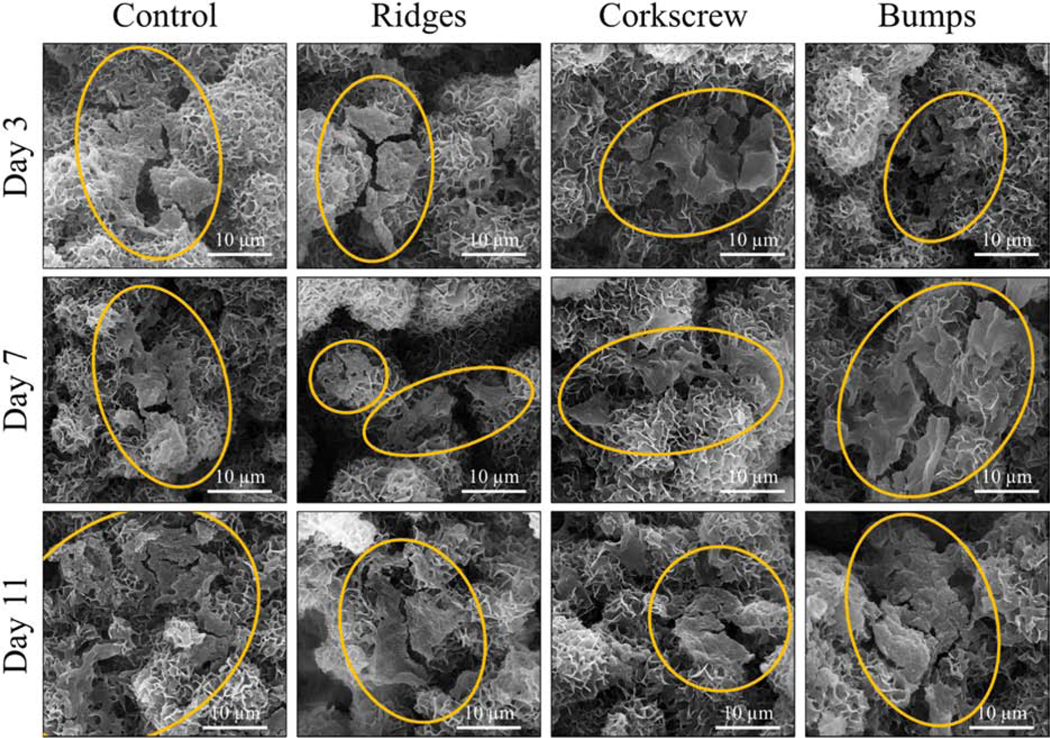
SEM micrographs of osteoblast cell culture morphology. All scaffold designs and timepoints show healthy osteoblast morphology on the sample surfaces. It is noted that the bumps scaffolds at day 7 and day 11 show more prominent osteoblast proliferation and denser spreading compared to all other samples, most likely due to capturing the cells during cell seeding.
Observing these micrographs is a microstructural change to all the TCP scaffolds’ visible surface where platelet-like apatite has formed. Apatite formation of synthetic calcium phosphates mimics physiological bone apatite and is essential for in vivo bone ingrowth [36,37]. There have been various reports on this apatite formation and, in this work, is heavily dictated by the β- and α- TCP phases identified. One such apatite is carbonated calcium-deficient hydroxyapatite (CDHA) [38,39]. One report showed a transformation of CDHA to β-TCP with shifts in the hydroxyl, carbonate, and phosphate bands at various calcination temperatures [40]. Hydroxycarbonate apatite is another, reported in tailorable resorbable scaffold research [41,42]. One work reports that a carbonated apatite layer originates from CDHA, and calcium carbonated apatite can induce the precipitation of another layer, octacalcium phosphate (OPC) [43]. As shown in the XRD, α-TCP phase is found in these β-TCP scaffolds after processing due to sintering. While β-TCP is stable in vitro, α-TCP is not. Their respective effects on scaffold dissolution rate behavior are an essential area of study for application in the bone tissue engineering field [44,45]. Additionally, many reports have shown α-TCP has a high affinity to convert to calcium deficient hydroxyapatite (HA), displaying ‘petal-like’ microstructure [46,47]. This is due to the precipitation of the surface, releasing calcium and phosphate ions specifically from α-TCP. It has been shown that TCP ceramics that do not have α-TCP, or any HA, in their composition will not convert to apatite while immersed in aqueous environments [48].
Another observation was made following the osteoblast cell culture. TCP is highly used as a bioresorbable material because of its ability to degrade over time and simultaneously act as a bioactive material that can aid bone healing. As seen in Fig. 8, the low magnification SEM micrographs show little to no degradation of scaffold surfaces, and the design topography has remained clear and visible. This result elucidates that the scaffolds all have stability in vitro for at least up to 11 days. This is an important observation because the purpose of using these complex structures is to impact biological properties positively, but their purpose would be ineffective if the designs were to degrade quickly compared to the main body of the scaffold. The dissolution behavior, and related biodegradation rate, should resemble that of new bone formation and remodeling to serve as an effective implant [49,50] These scaffolds’ residual porosity is low, limiting the amount of degradation seen in the culture media. While this result can be useful in specific bone disorder applications requiring higher mechanical strength and less biodegradation, this may not be ideal in all applications. The addition of pores could alter these scaffold’s degradation and dissolution rate, through increasing surface area at the expense of mechanical integrity.
Fig. 8.

SEM micrographs of osteoblast culture scaffolds at low magnification. These images do not showcase any degradation of scaffold surface details, and this indicates the stability of these scaffolds for the duration of the culture.
To better try to match the level of shape and topographical complexity to bone defects in low load-bearing graft applications, external features are fabricated onto cylindrical scaffolds. The success in the fabrication of external features is one step closer to producing truly personalized bone tissue implants that can match patient and defect site-specificity to aid bone healing. Future directions include pores and scaffold compositional changes mixing other calcium phosphates or additives for defect-specific patient-matched implants.
5. Conclusion
Crack-free fabrication of bone-like scaffolds with complex external structures is built using a binder jet-based 3D printer. Designs include vertical ridges, horizontal screw-like threads, and cylindrical bumps. Scaffolds are then utilized in vitro to understand the effects of external surface area on cellular proliferation. Results show that up to ~ 40% increase in bone scaffolds’ external surface area achieves a 2-fold increase in osteoblast proliferation in vitro. Evaluation of scaffold degradation during the culture reveals that the exterior architecture’s integrity is stable, even up to 11 days. Additionally, compressive strength testing reveals that the designed structures are not a compromising factor but enhance scaffold compressive strength by 30% compared to control. These 3D printed scaffolds showcase the feasibility of producing complex architectures on the exterior of bone-like scaffolds.
Supplementary Material
Acknowledgements
The authors would like to acknowledge financial support from the National Institutes of Health, NIAMS and NIDCR, under the grant number R01 AR066361-01 (PI: Bose) and R01 DE029204-01 (PI: Bose) and the National Science Foundation under the grant number CMMI-1538851. The authors would also like to thank the Franceschi Microscopy & Imaging Center and Photo Services at Washington State University. This content is solely the authors’ responsibility and does not necessarily represent the official views of the National Institutes of Health.
Footnotes
Declarations of Interest
None.
Declaration of interests
☒ The authors declare that they have no known competing financial interests or personal relationships that could have appeared to influence the work reported in this paper.
Publisher's Disclaimer: This is a PDF file of an unedited manuscript that has been accepted for publication. As a service to our customers we are providing this early version of the manuscript. The manuscript will undergo copyediting, typesetting, and review of the resulting proof before it is published in its final form. Please note that during the production process errors may be discovered which could affect the content, and all legal disclaimers that apply to the journal pertain.
References
- [1].Pneumaticos SG, Triantafyllopoulos GK, Basdra EK, Papavassiliou AG Segmental Bone Defects: From Cellular and Molecular Pathways to the Development of Novel Biological Treatments J. Cell. Mol. Med, 14 (2010), pp. 2561–2569, 10.1111/j.1582-4934.2010.01062.x [DOI] [PMC free article] [PubMed] [Google Scholar]
- [2].Tarafder S, Banerjee S, Bandyopadhyay A, Bose S. Electrically Polarized Biphasic Calcium Phosphates: Adsorption and Release of Bovine Serum Albumin Langmuir, 26 (2010), pp.16625–16629, 10.1021/la101851f [DOI] [PMC free article] [PubMed] [Google Scholar]
- [3].Cox SC, Thornby JA, Gibbons GJ, Williams MA, Mallick KK 3D Printing of Porous Hydroxyapatite Scaffolds Intended for use in Bone Tissue Engineering Applications Mater . Sci. Eng. C, 47 (2015), pp. 237–247, 10.1016/j.msec.2014.11.024 [DOI] [PubMed] [Google Scholar]
- [4].Becker ST, Bolte H, Krapf O, Seitz H, Douglas T, Sivananthan S, Wiltfang J, Sherry E, Warnke Endocultivation PH: 3D Printed Customized Porous Scaffolds for Heterotopic Bone Induction Oral Onc, 45 (2009), pp. e181–e188, 10.1016/j.oraloncology.2009.07.004 [DOI] [PubMed] [Google Scholar]
- [5].Zhou Z, Buchanan F, Mitchell C, Dunne N. Printability of Calcium Phosphate: Calcium Sulfate Powders for the Application of Tissue Engineered Bone Scaffolds Using the 3D Printing Technique Mater. Sci. Eng. C, 38 (2014), pp. 1–10, 10.1016/j.msec.2014.01.027 [DOI] [PubMed] [Google Scholar]
- [6].Butscher A, Bohner M, Doebelin N, Hofmann S, Müller R. New Depowdering-Friendly Designs for Three-Dimensional Printing of Calcium Phosphate Bone Substitutes Acta Biomater, 9 (2013), pp. 9149–9158, 10.1016/j.actbio.2013.07.019 [DOI] [PubMed] [Google Scholar]
- [7].Seitz H, Rieder W, Irsen S, Leukers B, Tille C. Three-Dimensional Printing of Porous Ceramic Scaffolds for Bone Tissue Engineering J. Biomed. Mater. Res. B. Appl. Biomater., 74 (2005), pp. 782–788, 10.1002/jbm.b.30291 [DOI] [PubMed] [Google Scholar]
- [8].Bose S, Suguira S, Bandyopadhyay A, Processing of Controlled Porosity Ceramic Structures via Fused Deposition Scripta Materialia, 41 (1999), pp.1009–1014, ISSN 1359–6462 [Google Scholar]
- [9].Inzana JA, Olvera D, Fuller SM, Kelly JP, Graeve OA, Schwarz EM, Kates SL, Awad HA 3D Printing of Composite Calcium Phosphate and Collagen Scaffolds for Bone Regeneration Biomater, 35 (2014), pp. 4026–4034, 10.1016/j.biomaterials.2014.01.064 [DOI] [PMC free article] [PubMed] [Google Scholar]
- [10].Mandal S, Meininger S, Gbureck U, Basu B. 3D Powder Printed Tetracalcium Phosphate Scaffold with Phytic Acid Binder: Fabrication, Microstructure and in situ X-Ray Tomography Analysis of Compressive Failure J. Mater. Sci: Mater. Med, 29 (2018), pp. 29, 10.1007/s10856-018-6034-8 [DOI] [PubMed] [Google Scholar]
- [11].Zhou Z, Cunningham E, Lennon A, McCarthy HO, Buchanan F, Dunne N. Development of Three-Dimensional Printing Polymer-Ceramic Scaffolds with Enhanced Compressive Properties and Tuneable Resorption Mater. Sci. Eng. C, 93 (2018), pp. 975–986, 10.1016/j.msec.2018.08.048 [DOI] [PubMed] [Google Scholar]
- [12].Hench LL: Bioceramics From Concept to Clinic J. Amer. Ceram. Soc, 74 (1991), pp. 1487–1510, 10.1111/j.1151-2916.1991.tb07132.x [DOI] [Google Scholar]
- [13].Deng Y, Liu X, Xu A, Wang L, Luo Z, Zheng Y, Deng F, Wei J, Tang Z, Wei S. Effect of Surface Roughness on Osteogenesis in vitro and Osseointegration in vivo of Carbon Fiber-Reinforced Polyetheretherketone–Nanohydroxyapatite Composite Inter. J. Nanomed, 10 (2015), pp. 1425, 10.2147/IJN.S75557 [DOI] [PMC free article] [PubMed] [Google Scholar]
- [14].Fielding GA, Bandyopadhyay A, Bose S. Effects of Silica and Zinc Oxide Doping on Mechanical and Biological Properties of 3D Printed Tricalcium Phosphate Tissue Engineering Scaffolds Den. Mater, 28 (2012), pp. 113–122, doi. 10.1016/j.dental.2011.09.010 [DOI] [PMC free article] [PubMed] [Google Scholar]
- [15].Tarafder S, Balla VK, Davies NM, Bandyopadhyay A, Bose Microwave-Sintered S. 3D Printed Tricalcium Phosphate Scaffolds for Bone Tissue Engineering J. Tissue Eng. Regen. Med, 7 (2013), pp. 631–641, 10.1002/term.555 [DOI] [PMC free article] [PubMed] [Google Scholar]
- [16].Ke D, Bose S. Effects of Pore Distribution and Chemistry on Physical, Mechanical, and Biological Properties of Tricalcium Phosphate Scaffolds by Binder-Jet 3D Printing Add. Manuf., 22 (2018), pp. 111–117, 10.1016/j.addma.2018.04.020 [DOI] [Google Scholar]
- [17].Bose S, Banerjee D, Robertson S, Vahabzadeh S. Enhanced in vivo Bone and Blood Vessel Formation by Iron Oxide and Silica Doped 3D Printed Tricalcium Phosphate Scaffolds Ann. Biomed. Eng, 46 (2018), pp. 1241–1253, 10.1007/s10439-018-2040-8 [DOI] [PMC free article] [PubMed] [Google Scholar]
- [18].Vu AA, Bose Vitamin D S. 3 Release from Traditionally and Additively Manufactured Tricalcium Phosphate Bone Tissue Engineering Scaffolds Ann. Biomed. Eng, 48 (2020), pp. 1025–1033, 10.1007/s10439-019-02292-3 [DOI] [PubMed] [Google Scholar]
- [19].Gbureck U, Grolms O, Barralet JE, Grover LM, Thull R, Mechanical Activation and Cement Formation of β-Tricalcium Phosphate. Biomater., 24 (2003), pp. 4123–4131, 10.1016/S0142-9612(03)00283-7 [DOI] [PubMed] [Google Scholar]
- [20].Thürmer MB, Diehl CE, dos Santos LAL, Calcium Phosphate Cements Based on Alpha-Tricalcium Phosphate Obtained by Wet Method: Synthesis and Milling Effects Ceram. Inter., 42 (2016), pp. 18094–18099, 10.1016/j.ceramint.2016.08.115 [DOI] [Google Scholar]
- [21].Balla VK, Bose S, Davies NM, Bandyopadhyay A. Tantalum—A Bioactive Metal for Implants Jom, 62 (2010), pp.61–64, 10.1007/s11837-010-0110-y [DOI] [Google Scholar]
- [22].Bose S, Banerjee A, Dasgupta S, Bandyopadhyay Synthesis A, Processing, Mechanical, and Biological Property Characterization of Hydroxyapatite Whisker-Reinforced Hydroxyapatite Composites J. Amer. Ceram. Soc, 92 (2009), pp. 323–330, 10.1111/j.1551-2916.2008.02881.x [DOI] [Google Scholar]
- [23].Misch CE, Qu Z, Bidez MW Mechanical Properties of Trabecular Bone in the Human Mandible: Implications for Dental Implant Treatment Planning and Surgical Placement J. Oral Maxillo. Surg, 57 (1999), pp. 700–706, 10.1016/S0278-2391(99)90437-8 [DOI] [PubMed] [Google Scholar]
- [24].Carter DR and Haynes WC The Compressive Behaviour of Bone as a Two-Phase Porous Structure J. Bone Joint Surg. Am, 59 (1977), pp. 954–962, [PubMed] [Google Scholar]
- [25].Hing KH Bone Repair in the Twenty-First Century: Biology, Chemistry or Engineering Phil. Trans. R. Soc. A, 362 (2004), pp. 2821–2850 10.1098/rsta.2004.1466 [DOI] [PubMed] [Google Scholar]
- [26].Byrne DP, Lacroix D, Planell JA, Kelly DJ, Prendergast PJ Simulation of Tissue Differentiation in a Scaffold as a Function of Porosity, Young’s Modulus and Dissolution Rate: Application of Mechanobiological Models in Tissue Engineering Biomater, 28 (2007), pp. 5544–5554, 10.1016/j.biomaterials.2007.09.003 [DOI] [PubMed] [Google Scholar]
- [27].Xu HH, Takagi S, Quinn JB, Chow LC Fast-Setting Calcium Phosphate Scaffolds with Tailored Macropore Formation Rates for Bone Regeneration J. Biomed. Mater. Res. A, 68 (2004), pp. 725–734, 10.1002/jbm.a.20093 [DOI] [PubMed] [Google Scholar]
- [28].Lee JB, Maeng WY, Koh YH, Kim HE Porous Calcium Phosphate Ceramic Scaffolds with Tailored Pore Orientations and Mechanical Properties Using Lithography-Based Ceramic 3D Printing Technique Mater, 11 (2018), pp. 1711, 10.3390/ma11091711 [DOI] [PMC free article] [PubMed] [Google Scholar]
- [29].Sun H, Hu C, Zhou C, Wu L, Sun J, Zhou X, Xing F, Long C, Kong Q, Liang J, Fan Y. 3D Printing of Calcium Phosphate Scaffolds with Controlled Release of Antibacterial Functions for Jaw Bone Repair Mater. Des, 189 (2020), pp. 108540, 10.1016/j.matdes.2020.108540 [DOI] [Google Scholar]
- [30].Miranda P, Pajares A, E Saiz,Tomsia AP, F. Guiberteau Mechanical Properties of Calcium Phosphate Scaffolds Fabricated by Robocasting J. Biomed. Mater. Res. A, 85, no. 1 (2008), pp. 218–227, 10.1002/jbm.a.31587 [DOI] [PubMed] [Google Scholar]
- [31].Baino F. and Vitale-Brovarone C. Mechanical Properties and Reliability of Glass-Ceramic Foam Scaffolds for Bone Repair Mater. Lett, 118 (2014), pp. 27–30, 10.1016/j.matlet.2013.12.037 [DOI] [Google Scholar]
- [32].Ducy P, Schinke T, Karsenty The Osteoblast G: A Sophisticated Fibroblast Under Central Surveillance Science, 289 (2000), pp. 1501–1504, 10.1126/science.289.5484.1501 [DOI] [PubMed] [Google Scholar]
- [33].Lane NE and Kelman A. A Review of Anabolic Therapies for Osteoporosis Arth. Res. Ther, 5 (2003), pp. 214, 10.1186/ar797 [DOI] [PMC free article] [PubMed] [Google Scholar]
- [34].Arpornmaeklong P, Suwatwirote N, Pripatnanont P, Oungbho K. Growth and Differentiation of Mouse Osteoblasts on Chitosan–Collagen Sponges Inter. J. Oral Maxillo. Surg, 36 (2007), pp. 328–337, 10.1016/j.ijom.2006.09.023 [DOI] [PubMed] [Google Scholar]
- [35].Oliva A, Salerno A, Locardi B, Riccio V, Della Ragione F, Iardino P, Zappia V. Behaviour of Human Osteoblasts Cultured on Bioactive Glass Coatings Biomater, 19 (1998), 1019–1025, 10.1016/S0142-9612(97)00249-4 [DOI] [PubMed] [Google Scholar]
- [36].Lotsari A, Rajasekharan AK, Halvarsson M, Andersson M. Transformation of amorphous calcium phosphate to bone-like apatite Nature Comm, 9 (2018), 1–11, 10.1038/s41467-018-06570-x [DOI] [PMC free article] [PubMed] [Google Scholar]
- [37].Kokubo T, Kushitami H, Sakka S, Kitsugi T, Yamamuro T. Solutions able to reproduce in vivo surface-structure changes in bioactive glass-ceramic A-W3 J. Biomed. Mater. Res, 24 (1990), 721–734, 10.1002/jbm.820240607 [DOI] [PubMed] [Google Scholar]
- [38].Liou SC, Chen SY, Lee HY, Bow JS, Structural characterization of nano-sized calcium deficient apatite powders Biomater., 25 (2004), 89–196, 10.1016/S0142-9612(03)00479-4 [DOI] [PubMed] [Google Scholar]
- [39].Viswanath B, Ravishankar N. Controlled synthesis of plate-shaped hydroxyapatite and implications for the morphology of the apatite phase in bone Biomater, 29 (2008), 4855–4863, j.biomaterials.2008.09.001 [DOI] [PubMed] [Google Scholar]
- [40].Gibson IR, Rehman I, Best SM, Bonfield W. Characterization of the transformation from calcium-deficient apatite to β-tricalcium phosphate J. Mat. Sci. Mat. Med, 11 (2000), 533–539, 10.1023/A:1008961816208 [DOI] [PubMed] [Google Scholar]
- [41].Roether JA, Boccaccini AR, Hench LL, Maquet V, Gautier S, Jérôme R. Development and in vitro characterisation of novel bioresorbable and bioactive composite materials based on polylactide foams and Bioglass® for tissue engineering applications Biomater, 23 (2002), 3871–3878, 10.1016/S0142-9612(02)00131-X [DOI] [PubMed] [Google Scholar]
- [42].Kokubo T, Kushitani H, Sakka S, Kitsugi T, Yamamuro T. Solutions able to reproduce in vivo surface-structure changes in bioactive glass-ceramic A-W3 J. Biomed. Mater. Res, 24 (1990), 721–734, 10.1002/jbm.820240607 [DOI] [PubMed] [Google Scholar]
- [43].Monteiro MM, da Rocha NCC, Rossi AM, de G. Almeida Soares, Dissolution properties of calcium phosphate granules with different compositions in simulated body fluid J. of Biomed. Mater. Res. Part A, 65 (2003), 299–305, 10.1002/jbm.a.10479 [DOI] [PubMed] [Google Scholar]
- [44].Tarafder S, Dernell WS, Bandyopadhyay A, Bose S SrO- and MgO-Doped Microwave Sintered 3D Printed Tricalcium Phosphate Scaffolds: Mechanical Properties and in vivo Osteogenesis in a Rabbit Model J. Biomed. Mater. Res. B. Appl. Biomat., 103 (2015), pp. 679–690, 10.1002/jbm.b.33239 [DOI] [PubMed] [Google Scholar]
- [45].Frasnelli M, Sglavo VM Effect of Mg2+ doping on beta–alpha phase transition in tricalcium phosphate (TCP) bioceramics Acta Biomater., 33 (2016), 283–289, j.actbio.2016.01.015 [DOI] [PubMed] [Google Scholar]
- [46].Gandolfi MG, Taddei P, Tinti A, Dorigo EDS, Prati C. Alpha-TCP improves the apatite-formation ability of calcium-silicate hydraulic cement soaked in phosphate solutions Mater. Sci. Eng.: C, 31 (2011), 1412–1422, 10.1016/j.msec.2011.05.012 [DOI] [Google Scholar]
- [47].Moraveji M, Nezafati N, Pazouki M, Hesaraki S. Bioorthogonal surface modified α-TCP-based bone filler for enhancement of apatite formation and bioactivity Ceram. Inter, 45 (2019), 5981–5986, 10.1016/j.ceramint.2018.12.068 [DOI] [Google Scholar]
- [48].Lin FH, Liao CJ, Chen KS, Sun JS, Lin CP Petal-like apatite formed on the surface of tricalcium phosphate ceramic after soaking in distilled water Biomater., 22 (2001), 2981–2992, 10.1016/S0142-9612(01)00044-8 [DOI] [PubMed] [Google Scholar]
- [49].Martin RA, Yue S, Hanna JV, Lee PD, Newport RJ, Smith ME, Jones JR Characterizing the Hierarchical Structures of Bioactive Sol–Gel Silicate Glass and Hybrid Scaffolds for Bone Regeneration Phil. Trans. Royal Soc. A. Math. Phys. Eng. Sci., 370 (2012), pp.1422–1443, 10.1098/rsta.2011.0308 [DOI] [PubMed] [Google Scholar]
- [50].Kim JA, Lim J, Naren R, Yun HS, Park EK Effect of the Biodegradation Rate Controlled by Pore Structures in Magnesium Phosphate Ceramic Scaffolds on Bone Tissue Regeneration in vivo Acta Biomat, 44 (2016), pp.155–167, 10.1016/j.actbio.2016.08.039. [DOI] [PubMed] [Google Scholar]
Associated Data
This section collects any data citations, data availability statements, or supplementary materials included in this article.