Abstract
Aim
To describe different modalities to record and transfer natural head position (NHP) to 3D facial imaging by using the virtual surgical planning software in three facial asymmetry patients.
Case Reports
Three patients with facial asymmetries (A, B, and C) were evaluated by means of dental and facial analysis, photographs, cone-beam computed tomography (CBCT) and digitized dental arches. Before starting the VSP workflow with Dolphin Imaging, NHP was recorded by three modalities and transferred to three-dimensional (3D) facial images as follows: (a) facial photographs taken with digital camera and the estimated NHP was transferred to 3D images by comparing lines and planes from both images; (b) cross-line level laser was used to place radiopaque markers on the face skin for recording the estimated NHP, which was transferred to 3D images by alignment of planes and markers in the software; and (c) photographs of the face were processed to generate facial surface mesh by using the Agisoft PhotoScan software, which maintained the same position of the estimated NHP in 3D for aligning the images of the soft tissue with the facial surface mesh by using superimposition. All the three patients underwent bi-maxillary orthognathic surgery.
Conclusion
There are different modalities using simple and available technologies in the clinical routine, but whose reproducibility, reliability and validation could not be assessed nor compared to each other. There was no trend for better predictability, feasibility and efficiency because the postoperative outcomes were adequate regarding the patients’ satisfaction and facial symmetry.
Keywords: Natural head position, Digital photograph, Laser level, Stereophotogrammetry, Orthognathic surgery
Introduction
Frankfort horizontal plane and sella-nasion reference have been used for years to standardize the lateral head orientation to obtain conventional radiographs [1, 2]. However, previous cephalometric studies have shown that intracranial reference lines have multiple variables and may be different from each side in the same patient [3, 4]. Facial asymmetry patients may present intrinsic deformation of anatomical structures, which can affect both facial and dental analyses and even the orthognathic surgery planning. Since the late 1950s, facial cosmetic and oro-maxillofacial surgeons, including orthodontists, have been using natural head position (NHP) to assess the individual’s actual appearance during routine clinical examination [5].
NHP is a standardized and reproducible position of the head in upright posture, with the eyes focused on a distant point at eye level [3]. Alternative methods of recording the head position have been recently considered to be reproducible, ranging from a profile photograph or lateral cephalogram using true vertical reference lines [5] to advanced technology devices unusual in the clinical routine [6].
Cone beam computed tomography (CBCT) or multislice computed tomography (MSCT) are useful in patients with dentofacial deformities and provide three-dimensional (3D) images, which can be associated with computer-aided design software in order to plan the treatment on a virtual scenario [7]. Although the patient’s head has to be stabilized during acquisition of 3D images, it is placed in a random orientation, which can result in over or underestimation of the dentofacial deformities [6]. Moreover, the scanning process of 3D images usually does not consider any physical reference line or plane, which provides topographic images of the soft and hard tissues without actual 3D orientation [8].
To start the virtual surgical planning (VSP) in orthognathic surgery, 3D facial images must be correctly reorientated by using the software for an appropriate assessment of the patients. Several studies have described methods to record the NHP, such as facial laser scanning [9], digital orientation sensor [10], stereophotogrammetry [11], facial markings along laser lines [12] clinical photographs and pose from orthography and scaling with iterations (POSIT) algorithm [13], including how each technique processes 3D images of the face to obtain the patient’s head position before the treatment planning. Nevertheless, most of these methods use technology devices which are not easily accessible in the clinical routine due to their high cost, low portability, and market unavailability.
Therefore, the aim of this work was to describe different modalities of recording estimated NHP in the clinic routine and of transferring it to 3D facial images by using the VSP software in three facial asymmetry patients based on treatment plan workflows and postoperative outcomes.
Case Reports
Three patients attended the Oral Maxillofacial Surgery Clinic of the Pedro Ernesto University Hospital of the State University of Rio de Janeiro, Brazil, for treatment of their dentofacial deformities, which involved aesthetical complaints regarding mandible, chin, asymmetry and functional restrictions. The patients were asked to look at their own face in a mirror positioned at the eye level in order to determine NHP [3]. If necessary, the surgeon could make some adjustment to correct the positioning of the head [14]. Facial and dental analysis was performed based on estimated NHP, with jaws in centric relation (CR) and lips at rest, according to traditional parameters as described by Arnett and Bergman [15]. Next, photographs of the head were taken with a digital camera (Nikon D300, Nikon Corporation, Tokyo, Japan) following the same technique used to obtain the estimated NHP, that is, jaws in centric relation and lips at rest. Plaster casts of the dental arches were made. Thus, a comprehensive examination of the patients for specific diagnosis was performed to recognize clinical features among hard and soft tissues in their faces (Table 1). The patients signed an informed consent form for treatment and use of their images for publication. All procedures were carried out according to the ethical principles and Declaration of Helsinki.
Table 1.
Clinical features of the patients’ faces
| Case A | Case B | Case C | |
|---|---|---|---|
| Qualitative data from facial analysis | |||
| Frontal view | |||
| Orbits (pupillary plane) | Symmetry parallel to the floor | Symmetry parallel to the floor | Symmetry parallel to the floor |
| Nose | Not shifted | Nose tip and wing shifted to the left | Nose wing shifted to the left |
| Labial philtrum | Shifted to the right | Shifted to the left | Shifted to the left |
| Lip line and oral commissures | Cant and vertical difference in leveling | Cant and vertical difference in leveling | Cant and vertical difference in leveling |
| Upper incisor midline to the mid-sagittal plane | Shifted to the right | Shifted to the left | Shifted to the left |
| Transverse occlusal plane | Vertical difference in leveling of tips canine | Vertical difference in leveling of tips canine | Vertical difference in leveling of tips canine |
| Gingival display at smile | More exposure to the left | More exposure to the right | No exposure |
| Lower incisor midline | Shifted to the right | Shifted to the left | Shifted to the left |
| Lower lip and chin | Shifted to the right | Shifted to the left | Shifted to the left |
| Inferior border of mandible | Bulkiness difference | Bulkiness difference | Bulkiness difference |
| Mandibular ramus length | Vertical difference | Vertical difference | No difference |
| Lateral view | |||
| Upper lip support (nasolabial angle) | Poor upper lip support (obtuse) | Poor upper lip support (obtuse) | Poor upper lip support (obtuse) |
| Upper Incisor | Retro-inclined | Retro-inclined | Retro-inclined |
| Labial-mental groove | Increased depth | Ordinary depth | Ordinary depth |
| Mandible and chin | Retrognathia | Retrognathia | Retrognathia |
Case A
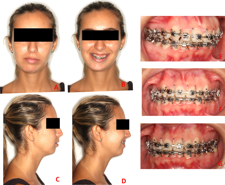
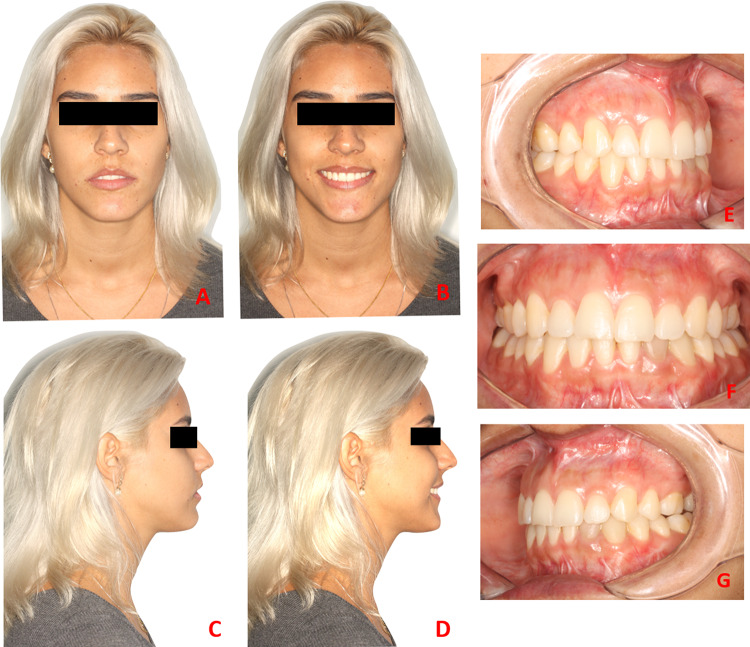
Facial analysis of a healthy 21-year-old female showed facial asymmetry and skeletal class II malocclusion (Fig. 1a–g). The clinical features are presented in Table 1.
Fig. 1.
a–d Preoperative evaluation at rest and smiling e–g Intraoral images
Case B
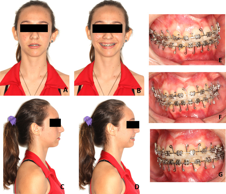
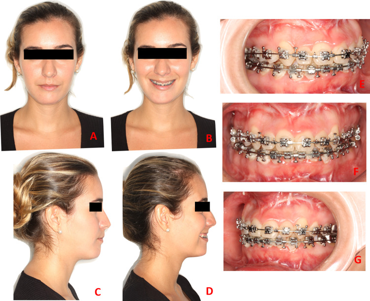
Facial analysis of a healthy 19-year-old female showed facial asymmetry and skeletal class I malocclusion (Fig. 2a–g). The clinical features are presented in Table 1.
Fig. 2.
a–d Preoperative evaluation at rest and smiling e–g Intraoral images
Case C
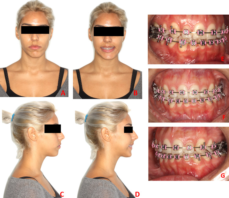
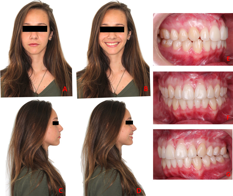
Facial analysis of a healthy 22-year-old female showed facial asymmetry and skeletal class II malocclusion (Fig. 3a–g). The clinical features are presented in Table 1.
Fig. 3.
a–d Preoperative evaluation at rest and smiling e–g Intraoral images
NHP and Virtual Surgical Planning
CBCT scans of all patients were obtained by using an i-CAT scanner (Image Sciences International, Hatfield, PA, USA) at a FOV of 22 × 16 cm, scanning time of 40 s, 120 kVp, 5 mA, isotropic voxel size of 0.4 mm and gray scale of 14 bits. During the acquisition of CBCT images, the head of the patients was stabilized to avoid image artifact and NHP was not obtained because the head was in random orientation. In addition, the scanning time was relatively long and the operators were not the surgeons who had initially performed the treatment planning workflow. The DICOM files were reconstructed into 3D images by using the Dolphin Imaging® 3D software, version 11.7 (Dolphin Imaging and Management Solutions, Chatsworth, CA, USA). The option “orientation calibration tool” was selected to record the NHP of the patients and the soft tissues three-dimensionally, thus rendering images by three different methods.
Case A
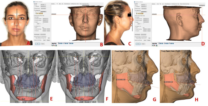
All facial photographs were taken in NHP and the 3D images were not displayed in NHP. NHP was readily retrievable from photographs by using true vertical and horizontal lines and compared to true vertical and horizontal planes in the 3D rendered images of the soft tissue. Pupillary line and soft tissue shapes (i.e., nasolabial angle, labiomental groove, upper and lower lips) were also some of the clinical features used as positioning references. Head position was estimated by adjusting the pitch and roll orientation in the 3D image of the soft tissue. All the process was based on the surgeon’s clinical estimation and subjective visual judgment (Fig. 4a–d).
Fig. 4.
a–d Images showing frontal and profile photographs in NHP associated with true horizontal and vertical lines to reorientate the 3D images into estimated NHP; e, f Preoperative measurements of occlusal cant and midline deviation, and postoperative measurements after virtual surgical planning; g, h pre- and postoperative profiles during simulation treatment planning
Case B
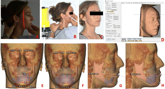
A cross-line level laser was attached to the camera tripod and placed 60 cm away from the patient’s face. After determining the NHP, the laser level beam was turned on and a red light projected reference markers onto the patient’s skin. Six radiopaque skin markers were sequentially placed on the patient’s face along the true horizontal (above the eyes—frontal region) and vertical (below the canthus of the eye) reference lines. Next, the radiopaque markers (metal beads) were attached to the patient’s skin and CBCT scan was obtained according to the aforementioned standards. NHP was transferred to the 3D rendered image by using the radiopaque skin markers aligned with the true horizontal and vertical plans and adjusted to pitch, roll and yaw orientation of the 3D image (Fig. 5a–d).
Fig. 5.
a–d Images showing NHP, laser line beam and reference radiopaque markers on the skin to record the NHP using the Dolphin Imaging software; e, f Preoperative measurements of occlusal cant and midline deviation, and postoperative measurements after virtual surgical planning; g, h Pre- and postoperative profiles during simulation treatment planning
Case C
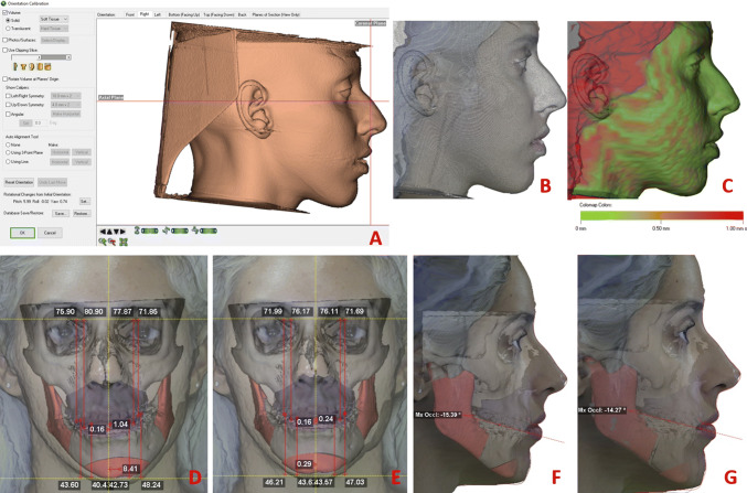
The set of facial photographs taken in NHP were further processed to generate a facial surface mesh by using a photogrammetry-based technique and Agisoft PhotoScan software (Agisoft LLC, St. Petersburg, Russia). In orientation tool, the 3D rendered image of the soft tissue was superimposed to the facial surface mesh by using an iterative closest point algorithm for alignment and recording, which automatically adjusted the pitch, roll and yaw axes of the 3D image. A color map was also generated to visually assess and quantitatively compare the NHP orientated with Dolphin Imaging software (Fig. 6a–c).
Fig. 6.
a–c Superimposition between 3D rendered image of the soft tissue and facial surface mesh from photographs by using an iterative closest point algorithm for alignment, which generated automatically a color map and adjusted the pitch, roll and yaw axes of the 3D image. d, e Preoperative measurements of occlusal cant and midline deviation, and postoperative measurements after virtual surgical planning; f, g pre- and postoperative profiles during simulation treatment planning
After head position orientation and superomposition of the digital dental arch models on each CBCT volume, a virtual model surgery was selected to perform the surgical planning based on the patient’s aesthetic-functional complaints, as well as three-dimensional cephalometric analysis (Figs. 4, 5, 6). According to these factors, bi-maxillary (maxilla and mandible) surgical approaches were planned based on counterclockwise rotation of the maxillomandibular complex and mentoplasty, exclusively for cases A and B. Le Fort I osteotomies were selected for slight advancement and occlusal correction in canines and molars by moving the maxilla upward (Case A and B) or downward (Case C) and by correcting the upper incisor midline in relation to the mid-sagittal plane. Bilateral sagittal mandibular osteotomies were selected to correct the transverse occlusal cant and inferior border of the mandible and to minimize the vertical difference between mandibular ramus length, lower incisor and chin midline in relation to the mid-sagittal plane, including mentoplasty for chin advancement and additional symmetry (Table 2). The surgical treatment plannings were simulated with a computer-aided design system, and the resulting postoperative virtual relationships (maxilla and mandible) were used to manufacture the intermediate and final stereolithographic splints. These splints are essential to guide the transfer of the preoperative surgical planning to the surgical procedure accurately.
Table 2.
Measurements of the movements of surgical virtual planning in millimeters
| 3D references | Case A | Case B | Case C | ||||||
|---|---|---|---|---|---|---|---|---|---|
| *A+/P− | *L+/R− | *D+/U− | *A+/P− | *L+/R− | *D+/U− | *A+/P− | *L+/R− | *D+/U− | |
| Maxilla | |||||||||
| ANS | + 3.13 | − 0.86 | + 0.10 | + 3.00 | + 1.38 | − 3.19 | + 0.58 | + 2.85 | − 4.55 |
| PNS | + 3.03 | + 0.41 | + 2.74 | + 4.75 | + 0.53 | + 4.27 | + 0.52 | + 1.72 | − 0.14 |
| Upper incisor tip midpoint | + 5.00 | + 2.30 | 0 | + 7.54 | − 1.89 | − 3.00 | + 3.50 | 0 | − 4.00 |
| Upper canine tip (L) | + 5.54 | + 2.58 | − 1.18 | + 7.42 | − 1.63 | + 0.07 | + 2.81 | + 0.04 | − 1.76 |
| Upper canine tip (R) | + 4.31 | + 2.31 | + 2.20 | + 7.42 | − 1.83 | − 3.55 | + 3.80 | − 0.09 | − 4.72 |
| Upper 6 mesial cusp tip (L) | + 5.56 | + 2.78 | − 0.90 | + 3.24 | − 1.36 | + 2.73 | + 2.27 | + 0.11 | − 0.16 |
| Upper 6 mesial cusp tip (R) | + 3.85 | + 2.67 | + 4.26 | + 7.10 | − 1.49 | − 1.50 | + 3.53 | − 0.05 | − 3.91 |
| Mandible | |||||||||
| Lower incisor tip midpoint | + 5.83 | + 4.28 | − 2.52 | + 7.03 | − 1.52 | + 3.00 | + 2.90 | − 0.80 | + 2.42 |
| Lower canine tip (L) | + 5.29 | + 4.09 | + 0.66 | + 6.98 | − 1.35 | − 0.63 | + 1.71 | − 1.07 | − 0.83 |
| Lower canine tip (R) | + 6.22 | + 3.80 | + 4.48 | + 7.02 | − 1.54 | − 3.44 | + 3.89 | − 1.13 | − 3.19 |
| Lower 6 mesial cusp tip (L) | + 4.85 | + 3.10 | + 0.02 | + 7.10 | − 1.23 | − 3.29 | + 0.77 | − 2.06 | − 1.21 |
| Lower 6 mesial cusp tip (R) | + 6.49 | + 2.87 | − 6.45 | + 6.91 | − 1.34 | + 1.26 | + 4.31 | − 2.18 | + 2.60 |
| B point | + 6.50 | + 6.40 | − 2.95 | + 9.40 | − 3.18 | + 1.93 | + 3.98 | − 2.60 | + 1.83 |
| Pogonion | + 13.22 | + 8.30 | − 2.36 | + 11.72 | − 4.86 | + 1.92 | + 4.91 | − 8.69 | + 1.56 |
| Gonion (L) | + 2.87 | + 2.01 | − 0.39 | + 1.71 | 0 | − 0.65 | + 1.37 | − 0.97 | − 0.06 |
| Gonion (R) | + 1.64 | + 2.16 | − 0.27 | + 4.90 | − 1.92 | − 0.81 | + 2.67 | − 0.55 | − 0.35 |
| Mandible back cut point (L) | + 5.32 | + 6.04 | − 1.15 | + 10.05 | − 3.25 | + 5.19 | + 1.81 | − 5.45 | + 3.43 |
| Mandible back cut point (R) | + 8.09 | + 7.32 | + 8.10 | + 9.45 | − 3.18 | − 1.26 | + 6.87 | − 5.56 | − 2.09 |
*Anterior and posterior, left and right, vertical (down and up)
Surgical Procedure
The surgical procedure was performed under general anesthesia. Initially, buccal access to the mandible was achieved through soft tissue incision on the external oblique line to the mesial aspect of the second molar laterally (a minimum of 5 mm of non-keratinized mucosa maintained in the buccal region). Sub-periosteal dissection of the buccal mucosa was then performed to the internal oblique line in the retromolar region, aiming at partially exposing the medial region and lingula of the mandible. Reciprocating saws (Stryker—CORE System) were used for sagittal osteotomy of the mandible bilaterally and finished with chisels and hammer. Stereolithographic surgical guides were then attached to the orthodontic appliance for maxillomandibular splinting with steel wire. Mandible and maxilla were stabilized at intermediate occlusion level, with the former being repositioned by means of rigid internal attachment to straight mini-plates and mono-cortical screws (System 2.0—Neoface—Neoortho Orthopedic Products).
Surgical access to the maxilla was performed buccally, with the sub-periosteal non-keratinized mucosa detachment extending from the floor of the nasal fossa to the pterygomaxillary region. Le Fort I osteotomy was performed by using a reciprocating saw (Stryker—CORE System) and finished with chisels. After osteotomy in the pterygomaxillary regions and mobilization of the maxilla, the walls of the maxilla were leveled following the virtual surgical planning by using rongeur forceps and rotatory burs. The final stereolithographic surgical guide was inserted along with the orthodontic appliances and steel wire was used to stabilize both maxilla and mandible at final occlusion. Finally, the maxilla was repositioned with rigid internal fixation by using L-shaped mini-plates in the zigomaticomaxillary regions and around the pyriform aperture (System 2.0—Neoface—Neoortho Orthopedic Products). In conjunction with the bi-maxillary orthognathic surgery, mentoplasty was performed to improve contour of the labiomental groove and mandibular symmetry. The surgical procedures followed the virtual treatment planning.
Postoperative Period
The patients were evaluated weekly in the first 2 months and monthly thereafter until the sixth month. Postoperative orthodontic treatments were maintained until completion.
Subjectively, the patients were satisfied with the results both aesthetically and functionally. After 1 year after the surgery, the outcomes for cases A, B and C were stable (Figs. 7, 8, 9).
Fig. 7.
a–d Postoperative evaluation at rest and smiling e–g Intraoral images
Fig. 8.
a–d Postoperative evaluation at rest and smiling e–g Intraoral images
Fig. 9.
a–d Postoperative evaluation at rest and smiling e–g Intraoral images
Discussion
For precise diagnosis, assessment and planning of the patients’ facial asymmetry, one of the steps is to obtain a proper and reliable orientation of the 3D images during VSP. Hence, in the process of determining the NHP in patients undergoing orthognathic surgery, different methods have been highlighted to record the natural position of the head in all three planes and to transfer its orientation to 3D images by using computer-aided surgery software [16]. Based on previous studies using photogrammetry [5, 16], we have developed simple methods and reasonable ways of recording the estimated NHP and transferring it to VSP software.
With the transition from 2D to 3D imaging, that is, from conventional methods to digital technology, orthodontics and surgeons have renewed their attention to new methods for determining an accurate and reliable head position in view of the importance of planning the surgical procedures for dentofacial deformities. Reviews defined clinical application and reproducible methods for recording and transferring the NHP to 3D imaging, highlighting that the estimated orientation of the head position was firstly defined as “estimated natural head position” or “natural head orientation” [5, 14]. Moreover, previous studies justified the reasons for modifying the NHP in some specific patients, as are the cases of mandibular prognathism or retrognathism, because they may present altered head positions hiding their dentofacial deformities [10, 17]. Therefore, we were very careful during the recording of NHP in dentofacial analysis and the taking of photographs. An experienced surgeon reorientated the NHP even if the position of the body and head of the patient was at rest when he or she was looking at the mirror positioned at eye level.
Leung et al. [6] performed a systematic review to evaluate the accuracy of different modalities to record NHP in 3D. The authors identified six modalities (i.e., stereophotogrammetry, facial markings along laser lines, clinical photographs and pose from orthography and scaling with iteration algorithm—POSIT, digital orientation sensing, handheld 3D camera measuring system, and laser scanning). From the eight articles selected, digital orientation sensing was the most common modality investigated (four studies) either in vitro or in patients. Although digital sensor and laser scanning showed good accuracy, their clinical use may be limited to their high cost and difficult portability. Most of the studies reviewed were in vitro, which may have biased the results. Hence, the authors emphasized that clinical trials need to be developed to assess the actual application of these methods in patients.
Previous in vitro and clinical studies have assessed the validity of digital orientation sensing to reproduce the NHP in 3D images derived from computed tomography [9, 10, 18, 19]. It consists in using a digital gyroscope attached to an individualized bite jig [9], but this equipment could minimally influence the pitch angle and change the posture of upper and lower lips during CT scans [13]. Although a slight variation in the NHP reproducibility may not be clinically significant [6], the method cannot distort the lips because their position is an important anatomical landmark in the surgical planning [20].
In the preoperative period, all clinical photographs were taken by the same surgeon after estimating the NHP for each patient. In other words, all the patients had their head reorientated before the frontal and lateral faces were photographed with a digital camera. Next, the photographs were used to record the estimated NHP in the patient in Case A. This method is based on comparing the frontal and lateral photographs to true vertical and horizontal lines, with 3D-rendered images of the soft tissue using coronal (as true vertical line) and axial (as horizontal plane) planes. From the dental and facial analysis, the surgeon could also use the clinical features to position the NHP in 3D-CBCT image. The reorientation of the 3D image was performed by adjusting the pitch and roll axes according to the surgeon’s subjective clinical judgment only. Although the NHP was properly reorientated on the 3D image by using software and postoperative outcomes, we have realized that this method had limitations, particularly in facial asymmetry patients because the yaw axis was not taken into account.
In an attempt to overcome the limitation regarding the clinical judgment, Kim et al. [13] and Yang et al. [20] reported that POSIT was an accurate and inexpensive method which does not alter the lip position. This method is based on a single frontal photograph taken from the patient or skull phantom in which ceramic spherical markers are attached to the surface (either skin or skull surface). Each marker is determined on the 2D image (i.e. photograph) and corresponded 3D image (i.e., CT) for calculating the head position by using the POSIT algorithm, which allows recording and reproducing the NHP. This method has high reproducibility and provides clinically acceptable results [13, 20]. We believe that the entire workflow of the POSIT method is based on markers and clinical photographs taken in NHP determined by operators using a digital camera. It is recommended that at least photographs should be used to reorientate the NHP on the 3D-CBCT images of the soft tissue. In our cases, the POSIT method would only have been applied if specific software was available for clinical routine.
From the NHP estimated in the preoperative period, radiopaque markers were placed along the horizontal and vertical laser lines projected onto the patient’s facial skin (Case B). CBCT scan was performed with the markers in position and the NHP was transferred to the 3D rendered image of the soft tissue by an operator, who checked whether markers were aligned with horizontal and vertical planes or made adjustments according to the radiopaque reference. As well as Damstra et al. [16], the method used in case B was considered a simple and fast way of obtaining the head position in all three axes (i.e., pitch, yaw, and roll). Furthermore, a retrospective study also used laser lines to position radiopaque markers on the face of sixteen patients in order to record the NHP clinically and determine it during the VSP process [12]. However, a systematic review reported that this technique should not be recommended because there are potential issues, such as lack of homogenous number and position of markers on the patient’s face, lack of intra- and inter-rater reproducibility regarding the placement and alignment of the markers in relation to the virtual planes, and lack of comparison with other methods [6].
Photogrammetry has been reported as being a promising method of soft tissue imaging because of advantages such as clinical applications, low cost, easiness of use and non-exposure to radiation for postoperative evaluations [21, 22]. A previous study reported on the high reproducibility and reliability of 3D stereophotogrammetric images after two observers had independently identified 49 soft tissue landmarks on the images of 20 patients twice. The results suggested that the landmarks were more accurately identified in the midline than paired landmarks in the face bilaterally [23]. Naudi et al. [22] adopted the iterative closest point (ICP) algorithm to record and superimpose images of the skin surface acquired by stereophotogrammetry and CBCT, reporting no identification of landmarks on both images. Regardless of its purpose and results, the superimposition of 3D photographs and CBCT images was accurate and could be used to ease the prediction of postoperative results during VSP.
Hsung et al. [24] developed a technique in which stereophotogrammetry was used to record the head position and reorientate 3D facial images in NHP. The results were accurate and the method was considered gold standard, but specific physical landmarks are needed, and it is not readily usable in the clinical practice. In Case C, we have found no methodological parameter describing the photogrammetry technique using the Agisoft PhotoScan software yet. Therefore, the estimated NHP was recorded by using a professional digital camera to produce 2D photographs of the patient’s face. Next, the photogrammetric technique was applied to this software specifically, in which the 3D digital topography is matched with the different photographic positions of the face by maintaining the same coordinate frames, thus generating a facial surface mesh.
As well as Naudi et al. [22], we have considered that 3D-CBCT and 3D photographic images of the soft tissue were similar to each other. The software was able to transfer the CBCT image of the soft tissue (test surface) to photogrammetry (reference surface) and there was no landmark to assist the ICP algorithm (collision map on Dolphin software). We have recognized that some regions should be removed for stereophotogrammetry (e.g., hair, ears and neck) because it could affect the alignment and the 3D-rendered image of the soft tissue might show defects (e.g., streak artifacts) at the tip of the nose and lateral regions of the face. However, no landmark or defect seemed to interfere with the ICP algorithm because the superimposition matched with the surface by iteratively computing the closest point on the test surface to a given point on the reference surface. With this, an accurate final alignment can be achieved [25]. After alignment between 3D surfaces on Dolphin Imaging software, we have observed a collision map (color map) showing better alignment between the surfaces on midline, lips, paranasal and chin regions. However, there were deviations (about 1 mm) at the lateral regions of the face, a finding similar to that reported by Naudi et al. [22].
Zhu et al. [8] evaluated the reliability regarding reorientation of 3D facial images of skeletal class III patients for estimated NHP by comparing it based on the method preconized by Hsung el al [11]. Their results indicated a moderate level of reliability for roll and yaw axes. Although clinicians could estimate NHP in 3D facial images, the authors highlighted that pitch axis was less reliable for estimating head position in those patients with symmetrical face. In all cases reported, we had no difficulty in adjusting the pitch axis of the head position in 3D facial images, but we were worried about the yaw axis for recording or transferring the NHP to 3D facial image in the beginning of VSP. Although all the patients presented facial asymmetry, they had no difference in ear height and orbital dystopia, and thus we used the eyes (i.e., pupils and orbital planes) to assist in the orientation of roll and yaw axes in the images.
Based on previous studies, our methods are simple and available for clinical routine as no important structure (i.e., lips, chin and soft tissue contour) was altered. Regardless of the method used to record and transfer NHP, an experienced surgeon recorded the NHP by using his own clinical judgment to estimate it. Therefore, we agreed that the success of a given method depends on the operator [6]. Despite the limitation of the present study due to the lack of validation to confirm the reliability and precision of different modalities in recording and transferring estimated NHP, we have described each step of the methods used in our cases and which should be considered alternatives to be adopted in the daily clinical routine.
Conclusion
The reproducibility, reliability and validation of different modalities have been neither assessed nor compared to each other. The cases reported showed that the treatment planning workflow was simple and provided satisfactory postoperative outcomes and facial symmetry in patients. Regardless of the modalities of recording and transferring the estimated NHP to virtual planning software, there was no trend for a specific patient in terms of better predictability, clinical feasibility and efficiency.
Funding
There was no funding for this study.
Compliance with Ethical Standards
Conflict of interest
The authors declare that they have no conflict of interest.
Ethical Approval
All patients assigned a release form because data (pre- and postopearative photographs, computerized tommographs) from subjects who had been undergone orthognathic surgery were used and they can be analyzed. All procedures were carried out ethical standards applicable in 1964 Helsinki Declaration.
Footnotes
Publisher's Note
Springer Nature remains neutral with regard to jurisdictional claims in published maps and institutional affiliations.
References
- 1.Bister D, Edler RJ, Tom BD, Prevost AT. Natural head posture—considerations of reproducibility. Eur J Orthod. 2002;24:457–470. doi: 10.1093/ejo/24.5.457. [DOI] [PubMed] [Google Scholar]
- 2.Hedayati Z, Paknahad M, Zorriasatine F. Comparison of natural head position in different anteroposterior malocclusions. J Dent (Tehran) 2013;10:210–220. [PMC free article] [PubMed] [Google Scholar]
- 3.Moorrees CF. Natural head position—a revival. Am J Orthod Dentof Orthop. 1994;105:512–513. doi: 10.1016/S0889-5406(94)70014-1. [DOI] [PubMed] [Google Scholar]
- 4.Bjerin RA. Comparison between the Frankfort horizontal and the sella turcica-nasion as reference planes in cephalometric analysis. Acta Odont Scand. 1957;15:1–12. doi: 10.3109/00016355709041090. [DOI] [Google Scholar]
- 5.Cassi D, De Biase C, Tonni I, Gandolfini M, Di Blasio A, Piancino MG. Natural position of the head: review of two-dimensional and three-dimensional methods of recording. Brit J Oral Maxillofac Surg. 2016;54:233–240. doi: 10.1016/j.bjoms.2016.01.025. [DOI] [PubMed] [Google Scholar]
- 6.Leung MY, Lo J, Leung YY. Accuracy of different modalities to record natural head position in 3 dimensions: a systematic review. J Oral Maxillofac Surg. 2016;74:2261–2284. doi: 10.1016/j.joms.2016.04.022. [DOI] [PubMed] [Google Scholar]
- 7.Marlière DAA, Demétrio MS, Schmitt ARM, Lovisi CB, Asprino L, Chaves Netto HDM. Accuracy between virtual surgical planning and actual outcomes in orthognathic surgery by iterative closest point algorithm and color maps: a retrospective cohort study. Med Oral Patol Oral Cir Bucal. 2019;24(2):e243–e253. doi: 10.4317/medoral.22724. [DOI] [PMC free article] [PubMed] [Google Scholar]
- 8.Zhu S, Keeling A, Hsung TC, Yang Y, Khambay B. The difference between registered natural head position and estimated natural head position in three dimensions. Int J Oral Maxillofac Surg. 2018;47:276–282. doi: 10.1016/j.ijom.2017.07.016. [DOI] [PubMed] [Google Scholar]
- 9.Xia JJ, McGrory JK, Gateno Teichgraeber JF, Dawson BC, Kennedy KA, Lasky RE, English JD, Kau CH, McGrory KR. A new method to orient 3-dimensional computed tomography models to the natural head position: a clinical feasibility study. J Oral Maxillofac Surg. 2011;69:584–591. doi: 10.1016/j.joms.2010.10.034. [DOI] [PMC free article] [PubMed] [Google Scholar]
- 10.Schatz EC, Xia JJ, Gateno J, English JD, Teichgraeber JF, Garrett FA. Development of a technique for recording and transferring natural head position in 3 dimensions. J Craniofac Surg. 2010;21:1452–1455. doi: 10.1097/SCS.0b013e3181ebcd0a. [DOI] [PubMed] [Google Scholar]
- 11.Hsung TC, Lo J, Li TS, Cheung LK. Recording of natural head position using stereophotogrammetry: a new technique and reliability study. J Oral Maxillofac Surg. 2014;72:2256–2261. doi: 10.1016/j.joms.2014.03.025. [DOI] [PubMed] [Google Scholar]
- 12.Bobek S, Farrell B, Choi C, Weimer K, Tucker M. Virtual surgical planning for orthognathic surgery using digital data transfer and an intraoral fiducial marker. The Charlotte method. J Oral Maxillofac Surg. 2015;73:1143–1158. doi: 10.1016/j.joms.2014.12.008. [DOI] [PubMed] [Google Scholar]
- 13.Kim DS, Yang HJ, Huh KH, Lee SS, Heo MS, Choi SC, Hwang SJ, Yi WJ. Three-dimensional natural head position reproduction using a single facial photograph based on the POSIT method. J Craniomaxillofac Surg. 2014;42:1315–1321. doi: 10.1016/j.jcms.2014.03.017. [DOI] [PubMed] [Google Scholar]
- 14.Lundström A, Lundström F, Lebret LM, Moorrees CF. Natural head position and natural head orientation: basic considerations in cephalometric analysis and research. Eur J Orthod. 1995;17:111–120. doi: 10.1093/ejo/17.2.111. [DOI] [PubMed] [Google Scholar]
- 15.Arnett GA, Bergman RT. Facial keys to orthodontic diagnosis and treatment planning. Part I. Am J Orthod Dentofac Orthop. 1993;103(4):299–312. doi: 10.1016/0889-5406(93)70010-L. [DOI] [PubMed] [Google Scholar]
- 16.Damstra J, Fourie Z, Ren Y. Simple technique to achieve a natural position of the head for cone beam computed tomography. Brit J Oral Maxillofac Surg. 2010;48:236–238. doi: 10.1016/j.bjoms.2009.10.001. [DOI] [PubMed] [Google Scholar]
- 17.Ahangar-Atashi MH, Kachoei M. Effect of chin position on natural head orientation reproducibility. Med Oral Patol Oral Cir Bucal. 2011;16:e317322. doi: 10.4317/medoral.16.e317. [DOI] [PubMed] [Google Scholar]
- 18.Pavlovcic U, Diaci J, Mozina J, Jezersek M. Characterization of the head-to-trunk orientation with handheld optical 3D apparatus based on the fringe projection technique. Biomed Eng Online. 2013;12:96. doi: 10.1186/1475-925X-12-96. [DOI] [PMC free article] [PubMed] [Google Scholar]
- 19.Liu XJ, Li QG, Tian KY, Wang XX, Zhang Y, Li ZL. Establishment and accuracy examination of gyroscope for recording and transferring natural head position. Beijing Da Xue Xue Bao. 2014;46(1):86–89. [PubMed] [Google Scholar]
- 20.Yang HJ, Han JJ, Hwang SJ. Accuracy of 3D reproduction of natural head position using three different manual reorientation methods compared to 3D software. J Craniomaxillofac Surg. 2018;46:1625–1630. doi: 10.1016/j.jcms.2018.06.013. [DOI] [PubMed] [Google Scholar]
- 21.Rasse M, Forkert G, Waldhäusl P. Stereophotogrammetry of facial soft tissue. Int J Oral Maxillofac Surg. 1991;20:163–166. doi: 10.1016/S0901-5027(05)80008-6. [DOI] [PubMed] [Google Scholar]
- 22.Naudi KB, Benramadan R, Brocklebrank L, Ju X, Khambay B, Ayoub A. The virtual human face: superimposing the simultaneously captured 3D photorealistic skin surface of the face on the untextured skin image of the CBCT scan. Int J Oral Maxillofac Surg. 2013;42:393–400. doi: 10.1016/j.ijom.2012.10.032. [DOI] [PubMed] [Google Scholar]
- 23.Plooij JM, Swennen GRJ, Rangel FA, Maal TJJ, Schutyser FAC, Bronkhorst EM, Kuijpers-Jagtman AM, Bergé SJ. Evaluation of reproducibility and reliability of 3D soft tissue analysis using 3D stereophotogrammetry. Int J Oral Maxillofac Surg. 2009;38:267–273. doi: 10.1016/j.ijom.2008.12.009. [DOI] [PubMed] [Google Scholar]
- 24.Hsung TC, Lo J, Li TS, Cheung LK. Automatic detection and reproduction of natural head position in stereo-photogrammetry. PLoS ONE. 2015;10(6):e0130877. doi: 10.1371/journal.pone.0130877. [DOI] [PMC free article] [PubMed] [Google Scholar]
- 25.Bels PJ, Mckay ND. A method for registration of 3D shapes. IEEE Trans Pattern Anal Mach Intell. 1992;14:239–256. doi: 10.1109/34.121791. [DOI] [Google Scholar]


