Abstract
Double-outlet right ventricle (DORV) is a type of ventriculoarterial connection in which both great arteries arise entirely or predominantly from the right ventricle. The morphology of DORV is characterized by a ventricular septal defect (location and relationship with the semilunar valve); bilateral coni and aortomitral continuity; the presence or absence of outflow tract obstruction; tricuspid-pulmonary annular distance; and associated cardiac anomalies. The surgical approach varies with the type of DORV and is based on multiple variables. Computed tomography (CT) is a robust diagnostic tool for the preoperative and postoperative assessment of DORV. Unlike echocardiography and magnetic resonance imaging (MRI), CT imaging is not limited by small acoustic window, need for anaesthesia and can be used in patients with metallic implants. Current generations CT scanners with high spatial and temporal resolution, wide detectors, high-pitch scanning mode, dose-reduction algorithms, and advanced three-dimensional post-processing tools provide a low-risk, high-quality alternative to diagnostic cardiac catheterization or MRI, and have been increasingly utilized in nearly every type of congenital heart defect, including DORV.
Keywords: Congenital heart disease, Double outlet right ventricle
INTRODUCTION
Double-outlet right ventricle (DORV) represents a complex congenital heart disease (CHD) in which both the great vessels arise entirely or predominantly from the right ventricle (RV). Extreme heterogeneity is evident in the anatomy and physiology of DORV, with a wide spectrum mimicking tetralogy of Fallot (TOF), large-ventricular septal defect (VSD), and transposition of great vessels (TGA).1) Transthoracic echocardiography (TTE) is the primary diagnostic tool used to assess cardiac anatomy and function. It is relatively inexpensive, readily available, and poses little risk, even to unstable patients. An echocardiogram, along with bed-side pulse oximetry, provides a definitive diagnosis of the pathophysiology, non-invasively in most of the cases. However, operator dependency; small acoustic window in adult patients, particularly those with extensive sternal scarring after multiple interventions; difficulty in determining the details of small, often sub-centimetre, structures and extracardiac vessels; and the poor reproducibly of ventricular size and function are inherent disadvantages that affect its diagnostic performance.2) Magnetic resonance imaging (MRI) is a promising imaging modality for congenital heart defects, but it is limited by higher costs, lesser availability, need for anaesthesia or sedation, and incompatibility with metallic devices (pacemakers, stents and occluder devices). Digital subtraction angiography, although long ago a mainstay of congenital cardiac imaging, is currently used only for hemodynamic evaluations rather than anatomic definitions. Computed tomography (CT) has emerged as an alternative and effective diagnostic tool in the imaging of CHDs. Recent advancements in CT technology, such as electrocardiogram (ECG) gating, high-pitch scanning, wide detectors, automated tube-voltage selection, and tube-current modulation have revolutionized its role in diagnosis and postoperative follow-up imaging of various CHDs, including DORV.3) This review explores the morphology and embryology of DORV; elucidates the role of CT in its diagnosis, including suggested protocols; and discusses various available surgical procedures and imaging features of their postoperative complications.
ANATOMY AND CLASSIFICATION
DORV requires both great vessels (200% rule) or the entire one vessel and 50% or more of the other (150%) to arise from the RV.4) Because of the extreme heterogeneity of hearts classified as DORV, its definition has been subjected to considerable debate. When described in the 1950s, a DORV was defined as a condition in which both great vessels arise completely from the RV. Since 1981, a “50% rule” involving an arterial valve or valves overriding the ventricular septum through a VSD, has been widely accepted. An overriding arterial trunk is considered to have arisen from the RV when more than half of the circumference of its valve belongs to the RV. DORV is not a single cardiac anomaly, but a heterogenous group with variable morphological features and spatial relationships at each cardiac segment. The abnormal position of the great vessels in association with various structural anomalies can lead to different physiological phenotypes, such a TOF, VSD, TGA, or univentricular heart. If both great vessels arise from the RV, the only pathway by which the left ventricle (LV) can empty itself is a VSD. Therefore, a VSD is always present in a DORV.5) Another commonly seen feature in DORVs is pulmonary stenosis (PS), which is present in approximately 75% of cases. The relationship of the VSD to the great vessels and the absence or presence of PS provides a basis for classification of DORVs. Four different anatomical-physiological variants are recognized and listed here in order of decreasing frequency6):
1. TOF-type variant (DORV with a subaortic VSD and PS)
2. TGA-type variant (DORV with a subpulmonary VSD but without PS), commonly called a Taussig-Bing anomaly
3. VSD-type variant (DORV with a subaortic VSD but without PS)
4. Univentricular heart-type variant (DORV with mitral atresia, unbalanced atrioventricular septal defects, or profound hypoplasia of one ventricle)
EMBRYOLOGY
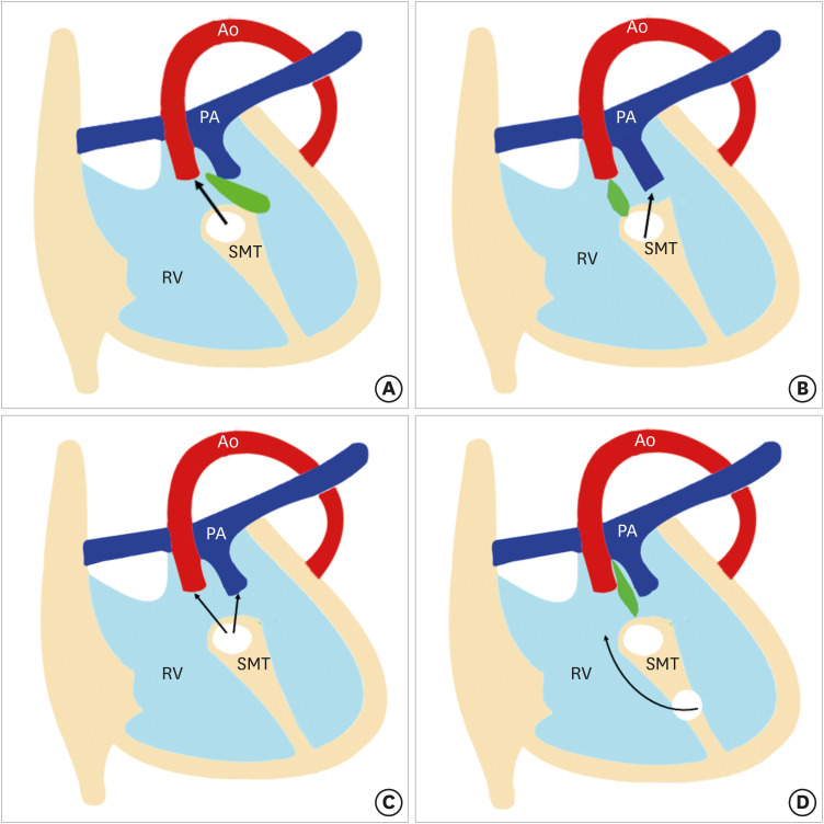
DORV results from impaired morphogenesis of the outflow tract (conotruncus). Traditionally, it was thought that DORV results from the failure of normal spiralling of pulmonary trunk and aorta, which leads to abnormal positioning.7) However, recent research suggests that primitive RV has double outlets containing the conotruncus. The aortic side migrates toward the LV and resolution of the subaortic conus leads to a fibrous connection between the aorta and mitral valve known as an aortomitral continuity. If this migration is incomplete, a DORV anatomy can persist beyond the early stages of development. In a normal heart, the aortic valve is in fibrous connection with the mitral valve, and the pulmonary valve is higher than the aortic valve. In DORV, aortomitral continuity is lost and both the aortic and pulmonary valves lie at the same level.8) Another proposed theory postulates that a DORV results due to misalignment and arrest of the interventricular septum. Various relationships between the outlet septum and septomarginal trabeculation (SMT) lead to different types of VSDs and DORV phenotypes. The outlet septum is a fibrous structure separating the two outflow tracts and forms the cranial margins of the interventricular communication channel. The SMT is a strap-like mass of myocardium that supports the septal surface. It has both cranial and caudal limbs. In DORV, the interventricular communication opens into RV between the 2 limbs of the SMT. If the outlet septum attaches to the cranial limb of the SMT, the interventricular communication is positioned in a subaortic location. Similarly, the attachment of the outlet septum to the caudal limb of the SMT leads to subpulmonary positioning of the interventricular communication. If the outlet septum shows neither cranial nor caudal attachment, the interventricular defect will become doubly committed. Lastly, if the distance between the VSD and semilunar valve is greater than the that of the aortic valve, it called remote or uncommitted VSD (Figure 1).9)
Figure 1. Four types of VSDs. The relationship between the outlet septum (green) and SMT defines the location of the VSD. In subaortic VSD, (A) the outlet septal attaches to the anterior limb of the septal band. In subpulmonic VSD, (B) the outlet septal attaches to the posterior limb of the septal band. In the doubly committed VSD, and (C) the outlet septum is absent. (D) A remote VSD is not related to the outlet septum and the distance between the VSD and the semilunar valve is greater than the size of the aortic valve.
RV: right ventricle, SMT: septomarginal trabecula, VSD: ventricular septal defect.
OVERVIEW OF THE MODALITIES
The diagnosis of DORV can be obtained by echocardiography, CT, cardiovascular magnetic resonance (CMR) or invasive angiography. Each modality has its own strengths and weaknesses. Transthoracic echocardiography (TTE) remains the diagnostic modality of choice. Its portability, accessibility, low cost, lack of radiation exposure, and extensive usage history have given the technique a wide appeal. It can identify all the essential features of a DORV in most of the cases. A combined assessment using an echocardiogram and bed-side pulse oximetry can provide a diagnosis non-invasively. The limitations of TTE are related primarily to the small acoustic window, particularly in infants, which precludes assessment of RV size and function, pulmonary arteries, and aberrant coronary anatomy.10) CMR provides a detailed assessment of cardiac and extracardiac morphology along with ventricular function analysis and flow quantification without radiation exposure. However, scan acquisition timings are lengthy and require sedation.11) Other disadvantages of CMR include higher cost, poor evaluation of lungs and airways, artifacts from non-MRI-compatible implants, lengthy post-processing time, gadolinium-induced nephrogenic systemic fibrosis, and limited availability, particularly in developing and less-developed countries.12) Although recent guidelines state that CMR can be performed in patients with implanted devices (MRI-conditional or not) if safety conditions are met, the device can still generate artifacts, and a packing box implanted in the chest wall can make the study non-diagnostic.13) Additionally, the risk of anaesthesia and emerging risks from gadolinium deposition in the central nervous system and other organs have prompted an FDA advisory on gadolinium contrast, making CMR a less-benign imaging option.14),15)
The role of cardiac catheterization is well established for the assessment of intra-cardiac pressures, coronary artery anatomy, and branch pulmonary arteries. Its invasive nature, need for prolonged sedation/anaesthesia, ionizing radiation, and catheter-related complications limit its use. Currently, it is used in determining pulmonary vascular resistance to check suitability for Fontan operation, and when catheter-based interventions such as balloon dilatation and stenting of the pulmonary arteries are anticipated.16),17)
Multi-detector computed tomography (MDCT) has evolved into a reliable tool for imaging pediatric patients with CHD. It can delineate preoperative cardiac anatomy demonstrating the relationship of heart to extracardiac structures; and can identify post-operative complications of DORV. While both MDCT and CMR provide high spatial resolutions, MDCT offers higher spatial resolution and CMR has a superior temporal resolution.18) Improved CT technology with wider detectors enables greater volume coverage and faster data acquisition. The introduction of helical prospective ECG-triggered acquisition at a relatively high pitch (3.4) has enabled gapless volume data acquisition in a single cardiac cycle.19) The advantages of MDCT include protocol flexibility, greater accessibility, relatively low cost, and superior evaluation of lung and airway abnormalities, which can occur concomitantly with complex CHD. There is no need for sedation or anesthesia with the current generation CT scanners, making CT an attractive alternative tool for pediatric patients. Additionally, CT is the modality of choice for patients with various metallic devices like internal cardiac defibrillators, and pacemakers (all of which are contraindicated for MRI). While surgical clips, cardiac valve prostheses, and occlusion devices are not contraindicated for CMR procedures, MDCT is preferable because these implants can cause signal loss and reduce image quality with CMR.20) Three-dimensional (3D) printing is an emerging technology in which CT or MRI datasets are used to produce 3D cardiac models of increasing complexity. A 3D model is a replica of a patient's anatomy that can be used for precise presurgical planning and simulation. Because of the volumetric high-resolution images and availability, cardiovascular CT is particularly suited to the requirements of 3D model generation.21)
The main limitations of CT include lack of access to the latest generation scanners and trained personnel, iodinated contrast administration, and ionizing radiations. Radiation-induced cancer that manifests after one or two decades is a significant concern that has restricted the use of MDCT to complex congenital heart disease and when it is needed as a problem-solving technique. However, modern scanners with wide detectors and dual-source technology have dramatically lowered the radiation exposure, and sub-millisievert scans are now possible in many children. Short scan times also significantly reduce the amount of contrast media, reducing the risk of contrast-induced nephropathy.22) The temporal resolution of CT does not approach that of MRI (20–50 ms) or angiography (1–10 ms), which can be performed without β-blockers. A single-source MDCT provides a temporal resolution of 135 ms. Modern scanners have addressed this challenge, and fast gantry rotation (0.3–0.4 seconds) combined with half-scan reconstruction and optional multisector reconstruction have dramatically improved temporal resolution to 50–65 ms.23)
PROTOCOLS
Protocol optimization for cardiac imaging can be challenging in pediatric patients due to complexity of congenital defects, high heart and respiratory rates, requirement for stringent dose reduction, and non-cooperative patients. At least 64 slice CT scanner is required to obtain optimum image quality. The newer generation CT scanners, with advanced features like dual-source technology, wide-detector system, high-efficiency detectors, greater X-ray tube power, and improved image processing, have consolidated the role of cardiac CT in children, particularly in unsedated patients with higher heart rates. Second-generation dual-detector scanners offer a new technique, called high-pitch helical mode, in which the pitch can be increased upto 3.4 without missing data, as data gaps are filled by the second detector. The primary benefit of the high-pitch mode is high temporal resolution and short scan time. A wide-detector scanner utilizing a 320/640-slice detector is another appealing technology. The increased z-axis volume coverage from 12 cm (in a 256-slice MDCT) to 16 cm (in 320/640-slice MDCT) produces temporally uniform images with homogeneous contrast enhancement in no more than 0.3 seconds.24) With such short scan time, both high-pitch mode and volumetric scanning (in a wide-detector scanner) can image the whole heart within a single cardiac cycle, even in patients with high heart rates. Furthermore, by reducing or eliminating the need for overlapping helical imaging, radiation exposure can be reduced by 60% to 80% compared with 64-detector scanners. These techniques have obviated the need for breath-holding and sedation in neonates and infants.25),26)
Non-ionic, low- or iso-osmolar iodinated contrast agents are used universally due to their safe nature. The antecubital vein is the most preferred intravenous access site. The size of the intravenous catheter depends upon the patient's age: usually 22–24 gauge for younger children, 20–22 gauge for older children and 18 gauge or larger for adolescents. The intravenous contrast volume is calculated from body weight (1–2 mL/kg). The combined volume of contrast and saline flush should be kept to 2–3 mL/kg, which is well tolerated without any hemodynamic consequences. Bolus tracking (automatic or manual) is the preferred method to trigger the scan. In automatic bolus tracking, the region of interest (ROI) is placed in the LV or proximal descending thoracic aorta. A set threshold between 100 and 150 HU is selected to trigger the scan, with a scan delay of 2–5 seconds depending on the CT model. The scan delay time is 2–4 seconds with 64-slice MDCT due to inherent interscan and image reconstruction delays. A 320-slice MDCT has no delay, except the time used for potential tube repositioning and instructing patients to hold their breath. Automatic bolus tracking is problematic in infants and younger children due to patient movements, which can cause a scan to start too early or too late. Manual bolus tracking is helpful in this situation. The monitoring sequence is placed at the mid-heart level to allow simultaneous visualization of cardiac chambers and descending aorta. The ROI is placed outside the body. Manual initiation of the scan is done when the contrast is visualized in all four cardiac chambers and the descending thoracic aorta.26) The assessment of DORV requires simultaneous opacification of both ventricles. This is achieved by biventricular or triphasic protocols. Two different contrast-injection methods are available in triphasic protocols. One method gives half the contrast at the usual arterial rate according to patient size and the remainder at a slower rate, followed by a saline flush. In second method, the injection rate is kept constant and 100% contrast in administered in the first phase followed by a contrast: saline mix (e.g., 30%:70% to 50%:50% mix) in second phase. Either method will result in biventricular opacification during image acquisition.26),27) Usually a single phase acquisition showing biventricular opacification is sufficient for evaluation of cardiac and extracardiac anatomy. However, DORV patients with remote VSD who have undergone Fontan repair require a delayed venous phase (60–90 seconds after initiation of contrast injection) for appropriate opacification of the Fontan circuit and pulmonary arteries.
There are 2 acquisition modes: non-ECG-gated and ECG-gated. As echocardiography is an effective tool for delineating intracardiac anatomy and pathology, most cardiac CT acquisitions are non-ECG-gated and aimed at visualization of extracardiac structures (pulmonary arteries, aortopulmonary collaterals, and airways). ECG-gated acquisition is needed for ventricular functional analysis and for assessing structures prone to cardiac motion artifact (aortic roots and coronary arteries). Functional assessment using cardiac CT is used primarily in patients having contraindications to CMR or when there a high likelihood of non-diagnostic CMR. With advancements in surgical techniques and medical care, the majority of CHD patients are now expected to survive to adulthood and even to advanced ages. Much of the morbidity in CHD is from RV or LV failure and arrhythmia, which necessitates the placement of electrophysiology devices.28),29) These devices can degrade the CMR image quality. Cardiac CT is a reasonable alternative modality for functional assessment in such patients. Multiple published reports have shown close correlation between cardiac CT and CMR for evaluating ventricular systolic function. The use of prosthetic valves in CHD is also increasingly and patients are frequently referred for prosthetic valve evaluation.30) CT has been shown to be an effective method for evaluating both prosthetic valve function and paravalvular leaks.31) Evaluation of coronary arteries is the another important indication for gated acquisition. All DORV patients with subpulmonic VSD without PS undergo VSD tunnel repair with arterial switch operation. The surgically created proximal pattern of the main coronary arteries promote unfavourable changes in the postoperative period, such as acute vessel angulation and compression. Coronary CT angiography using gated acquisition provides useful and accurate information for postoperative management and selection of high-risk patients.32)
There are 2 modes of ECG-gated acquisition, prospective, and retrospective. A prospective ECG-gated mode is a dose-saving mode in which data is acquired in a narrow-predefined phase of cardiac cycle, i.e., end systole (30%–40%) or end diastole (70%–80%). In retrospective ECG-gated mode, the data is acquired over the entire RR interval of a cardiac cycle, providing multi-segment reconstruction (0%–100%). Cardiac anatomy and coronaries can be evaluated with prospective ECG gating, while functional assessment (ventricular or valvular) requires retrospective gating. Selecting the proper cardiac phase is important in prospective gating, which is usually late diastole (70%–80%) if the heart rate is less than 80 bpm and end systole (30%–40%), if the heart rate is more than 80 bpm. Use of an absolute trigger delay as opposed to a relative (percentage) trigger delay is recommended while performing cardiac CT in children with a heart rate above 80 bpm to ensure maximum image quality.33) A consensus document of the Society of Cardiovascular Computed Tomography suggests a scan window in absolute milliseconds for prospective ccoronary CT angiography based on the recalculation of a 35%–55% systolic percentage scan phase.26) For example, in a patient with a heart rate of 75 bpm and an RR interval of 800 ms, the 35%–55% systolic phase will correspond to a 210–440 ms absolute scan window. Dual-source CT offers the advantage of flexibility in choosing the acquisition window. A quick-step acquisition window of 220 ms provides rapid acquisition but limited flexibility for different phase reconstruction. In comparison, a 330 ms acquisition window with an extended imaging angle from 260° to 460° provides a ± 8% phase shift and therefore flexibility in selecting the cardiac-phase reconstruction retrospectively. For example, in a neonate with a 505 ms RR cycle time, it is possible to reconstruct the window between 170 and 350 ms when the acquisition is set at end systole.33)
In retrospective ECG-gated mode, data is acquired continuously throughout the cardiac cycle. It provides a large volume of data over the entire cardiac cycle but at the cost of high radiation exposure which is 3 to 4 times that of a prospective mode. However, reliable image quality can be obtained in heart rates of up to 170 bpm. Older CT scanners using retrospective ECG-gated scan mode have reported effective doses up to 28 mSv per cardiac scan.34) Since then, innovations such as prospective ECG gating, high-pitch helical scanning, ECG-controlled tube-current modulation, wider detector coverage, and iterative reconstruction techniques have dramatically lowered the radiation dose.35),36) Today, sub-millisievert scans are possible in many children.37) Jin et al.38) compared the image quality and radiation doses of retrospective and prospective ECG-gated, dual-source CT imaging in pediatric patients with congenital heart diseases. The mean estimated effective dose was higher for a retrospective ECG-gated helical scan compared with a prospective non-helical scan (0.79 vs. 0.21 mSv, respectively, p < 0.01). Marked dose reduction (73%) was seen using prospective gating compared with retrospective gating.38) Similarly, a study at Great Ormond Street Hospital NHS Trust achieved a dose reduction of 64% by using prospective gating instead of retrospective gating.39) The Image Gently Alliance's “Have-a-Heart” campaign recently published radiation-management guidelines for pediatric cardiovascular CT. The aim of these guidelines is to minimize radiation doses and standardize imaging parameters across pediatric centers.34)
Image quality deteriorates when the heart rate exceeds 70 bpm, beat-to-beat variation is 10 bpm, and the body mass index is greater than 30 kg/m2.40) Using a 320-slice MDCT, with 320 × 0.5 mm detector elements, a 350 ms rotation time, and an anatomic coverage of 16 cm, coronary artery imaging in children can be performed with a single shot. The recommendations state single-beat acquisition if the heart rate is less than 65 bpm; two-beat acquisition if the heart rate is 65–75 bpm; and three-beat acquisition when the heart rate exceeds 75 bpm. Prospective gating is usually selected if the heart rate is below 80 bpm, and retrospective gating with tube-current modulation is used if the heart rate is high. Artifacts causing image degradation are commonly seen in children due to their intrinsically rapid heart rates. However, studies have shown that 256- and 320-slice MDCT and dual-source MDCT can provide heart-rate-independent image quality with retrospective ECG gating, which is not possible with 64-slice MDCT.41)
IMAGING APPROACH FOR PREOPERATIVE ASSESSMENT
Careful depiction of preoperative anatomy leads to optimal surgical approach and improved patient outcome. A diagnosis of DORV is encompassed by vigilant description of the VSD, including its relationship with the semilunar valves; conus and aortomitral continuity; great vessels relationship; presence or absence of any aortic and pulmonary outflow tract obstruction; coronary artery anatomy; and associated cardiac lesions.42)
DORV is often associated with complex and unique geometry. The echocardiography, 2D CT, and MRI of such complex cases does not always provide all the information needed to choose an operative approach (univentricular or biventricular). A 3D printed model provides better insight into surface spatial orientation and intracardiac anatomy compared with conventional imaging. These models are useful adjuncts in preoperative assessment of complex DORV. A 3D printed model enables better understanding of the spatial orientation of the heart in the thorax; size and location of the VSD; relationships of the great arteries and the semilunar valves; and the anticipated dimensions and orientation of the surgically planned interventricular baffle. Recent applications of 3D printing include: interventional preoperative planning and simulations; patient-specific hemodynamic evaluations; testing of novel procedural pathways; and use of sterilized models during surgical procedures for enhanced structural orientation. Patient-specific presurgical planning may reduce surgery time, leading to fewer complications. This may decrease reintervention rates, shorten postoperative stays, and lower health care costs.43),44) A brief description of the various modifiers is presented below.
VSD
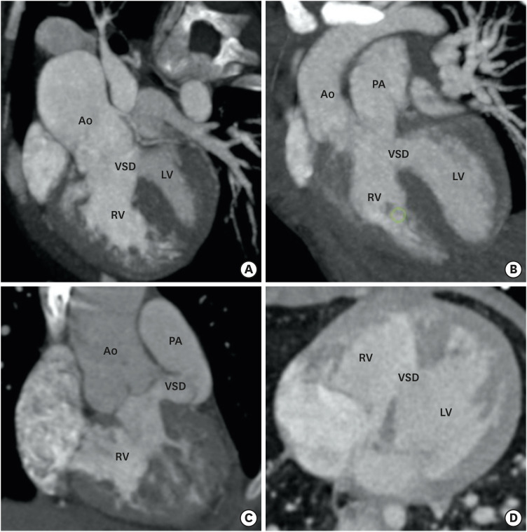
The location of the VSD in DORV is fairly constant and conoventricular. A VSD is typically defined according to its relationship with the conus as subaortic, subpulmonic, doubly committed, remote, or uncommitted. The most common subaortic VSD, is seen in approximately 50% of the patients. It is positioned beneath the aortic valve between the two limbs of the SMT.45) A subpulmonic VSD is found in approximately 30% of patients and is located beneath the pulmonary valve .46) Both the subaortic and subpulmonic VSD are separated from the corresponding valves depending upon the presence and length of subaortic or subpulmonic conus. If the conus is absent, the valve will override the VSD and form a superior border (juxtaaortic or juxtapulmonary). The doubly committed VSD is seen in approximately 10% of cases and it lies immediately beneath the aortic and pulmonary valve leaflets between the limbs of SMT. A remote or uncommitted VSD is seen in 10% of patients. It is not nestled within the limbs of SMT but in the inlet septum (Figure 2).
Figure 2. Types of VSD. (A) A reformatted coronal CT angiography image indicates the subaortic position of VSD. (B) A reformatted coronal CT angiography image indicates the subpulmonic position of the VSD. (C) A reformatted coronal CT angiography image indicates the doubly committed VSD. The VSD is located in relationship to both semilunar valves. (D) An axial CT angiography image shows the remote intramuscular VSD.
Ao: aorta, CT: computed tomography, LV: left ventricle, PA: pulmonary artery, RV: right ventricle, VSD: ventricular septal defect.
In most of the cases, the VSD is in the outlet portion, but it can also involve inlet or apical trabecular septum. If it involves the inlet septum, its exact proximity with tricuspid leaflets is a critical factor, as intraventricular baffling may compromise the size and function of tricuspid valve. It is also essential to note the size and multiplicity of the VSD, which is usually single and greater in diameter compared with an age-matched normal aortic valve. If the diameter of the VSD is smaller than that of the aortic valve, it is considered restrictive.47),48)
CONUS AND AORTOMITRAL CONTINUITY
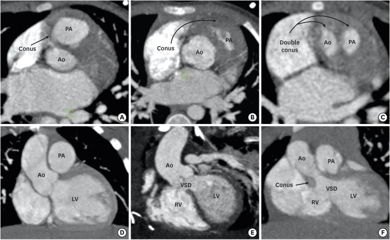
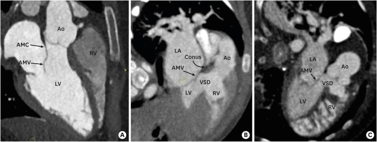
Conus refers to the thick muscular structure between the leaflets of the arterial and atrioventricular valves. In the primitive ventricle, it is present in both subpulmonic and subaortic regions. During the embryological development, the subaortic component get resorbed and is represented by aortomitral fibrous continuity. The subpulmonic component persists and separates the pulmonary and tricuspid valve. Since, DORV is characterized by failure of aortic migration to the LV, the subaortic conus also persists (Figures 3 and 4). Initially, the presence of bilateral conuses was used as a prerequisite for the diagnosis of DORV and to differentiate it from the TOF in the gray-zone status of aortic overriding of RV. However, Ebadi et al.49) reported variability in the morphology of the infundibulum in DORV specimens. Out of 100 DORV specimens, complete bilateral muscular conuses were present only in 23, and some degree of continuity was noted between semilunar and atrioventricular (AV) valves in 49% of the patients. Bilateral conuses are rarely found in a normal heart also.50) This suggests that the presence of bilateral conuses and discontinuity between semilunar and AV valves should not be used as a diagnostic criteria for DORV. The status of the conus, however, must be documented because it can affect the choice of surgical method. The length of the conus determines the location of the VSD relative to the semilunar and tricuspid valves. For a given location of the VSD, longer the conus or infundibulum the farther the VSD is from the aortic valve.
Figure 3. Conus (infundibulum). (A, D) Axial and coronal CT angiography images show a subpulmonic conus in a normal individual. (B, E) Axial and coronal CT angiography images indicate the subpulmonic conus in a patient with TOF. The subaortic conus is absent. Absence of the subaortic conus is used to differentiate a TOF from a DORV in the gray zone. (C, F) Axial and coronal CT angiography images indicate the double coni (subpulmonic and subaortic) in a patient with a DORV.
Ao: aorta, CT: computed tomography, DORV: double-outlet right ventricle, LV: left ventricle, PA: pulmonary artery, RV: right ventricle, TOF: tetralogy of Fallot, VSD: ventricular septal defect.
Figure 4. Aortomitral continuity. (A) A reformatted coronal CT angiography image indicates a preserved AMC in a normal individual. Fibrous continuity is evident between the noncoronary and left coronary leaflets of the aortic valve and AML. (B) A reformatted coronal CT angiography image indicates a preserved aortomitral continuity in a patient with a TOF. (C) A reformatted coronal CT angiography image indicates the loss of aortomitral continuity in a patient with a DORV. The subaortic conus is visible between the aortic valve and anterior mitral leaflet.
Ao: aorta, AMC: aortomitral continuity, AML: anterior mitral leaflet valve, AMV: anterior mitral valve, CT: computed tomography, DORV: double-outlet right ventricle, LA: left atrium, LV: left ventricle, PA: pulmonary artery, RV: right ventricle, TOF: tetralogy of Fallot, VSD: ventricular septal defect.
GREAT-VESSEL RELATIONSHIP
Two commonly seen great-vessel relationship patterns in DORVs are spiral and parallel. In most of the cases, a normal spiral pattern is seen with aorta lying rightward and posterior to the pulmonary trunk. The spiral type of great vessel relationship pattern is almost always associated with a subaortic VSD. In the parallel relationship pattern, the great vessels do not spiral around each other and aorta can be seen either side-by-side and rightward to the pulmonary trunk, or anterior and rightward to pulmonary artery (D-malposition) or very rarely leftward and anterior to the pulmonary artery (L-malposition). The parallel pattern is usually associated with a subpulmonic VSD. The L-malposition is the rarest type of great-vessel relationship and is usually associated with the subaortic VSD, pulmonary stenosis, and anomalous courses of the right coronary artery (Figure 5). Although the position of the VSD can be predicted by the type of great-vessel relationship, these are only generalizations and not strict rules.1)
Figure 5. Great-vessel relationship. (A) An axial CT angiography image indicating the posterior and rightward location of the Ao to the PA (normal relationship). (B) An axial CT angiography image indicates the anterior and rightward location of the Ao to the PA (D-TGA type). (C) An axial CT angiography image indicating the side-by-side and leftward orientation of the Ao to PA (cc-TGA type).
Ao: aorta, cc-TGA: congenitally corrected transposition of the great artery, CT: computed tomography, PA: pulmonary artery.
VENTRICULAR OUTFLOW TRACT OBSTRUCTION
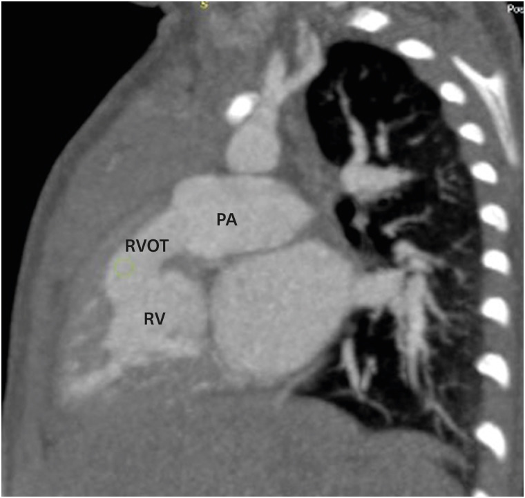
When the VSD is committed to a semilunar valve, the non-committed semilunar valve narrows between the free wall of the infundibulum and outlet septum. In other words, subaortic outflow tract obstruction is seen with subpulmonic VSD, and subpulmonic outflow tract obstruction is seen with a subaortic VSD. Pulmonary outflow tract obstruction is usually infundibular but valvular (hypoplasia or atresia) or versions that involve central pulmonary artery are also possible (Figure 6). Subaortic stenosis is uncommon, usually seen in Taussig-Bing anomaly and is contributed by accessory tissue or hypertrophied muscle bundles.42)
Figure 6. RVOT obstruction. A sagittal reformatted CT image indicating mild RVOT obstruction. CT: computed tomography, PA: pulmonary artery, RV: right ventricle, RVOT: right ventricular outflow tract.
VENTRICULAR VOLUMES
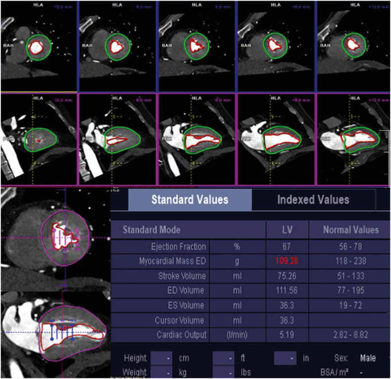
Biventricular repair requires ventricles of adequate volumes. The creation of an intraventricular tunnel or baffle compromises the volume of the RV because a part of the RV is incorporated into the left ventricular outflow tract (LVOT). It is therefore important to assess preoperative RV cavity size and estimate the volume of the remaining RV after the intended surgical approach. If there is a tricuspid or mitral atresia or hypoplastic LV, staged palliative repair is carried out as single functional ventricular operation. There are no uniform criteria for univentricular or biventricular repair in hypoplastic LV, but it has been proposed that in patients with critical aortic stenosis, an indexed LV end-diastolic volume < 20 mL/m2 is associated with poor prognostic outcome (Figure 7).51),52)
Figure 7. Example of left ventricular systolic function calculated using short- and long-axis images from dual-source CT coronary angiography.
CT: computed tomography, ED: end-systolic, ES: end-systolic, LV: left ventricle.
DORV VARIANTS
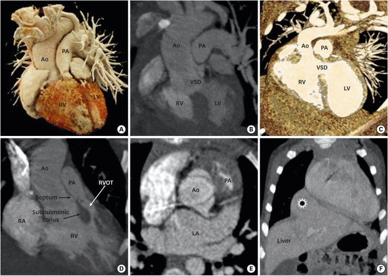
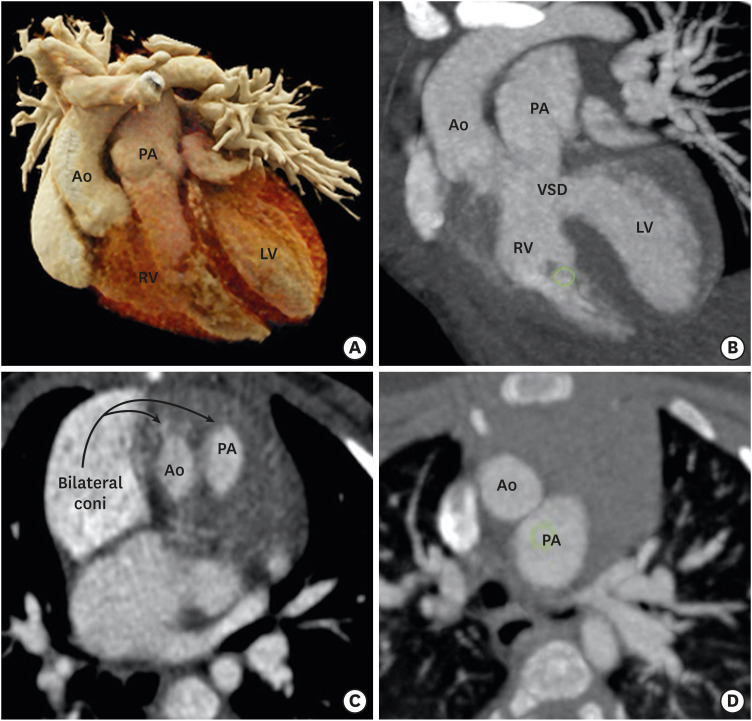
DORV is not a single entity, but a spectrum of varying morphological features at each cardiac segment. The relationship between the VSD and great vessels, outflow tract obstruction, and the anatomical orientation of atrioventricular valves determine the clinical course and the surgical management of DORV. As described above, four common anatomical-physiological variants of DORV are known, including TOF, TGA, VSD, and univentricular types. The TOF variant is characterized by a DORV with subaortic VSD and variable degrees of pulmonary stenosis. The aorta overrides the VSD and pulmonary valve is located anteriorly and superiorly. The pathophysiology is determined by pulmonary stenosis, which increases with age (Figure 8).53) A TGA variant is characterized by transposition of the great vessels and subpulmonic VSD. The great vessel trunks run parallel to each other rather than spiralling, the aorta being rightwards and anterior to the pulmonary trunk. This configuration is also called Taussig-Bing anomaly.54) The VSD variant is characterized by subaortic VSD without pulmonary stenosis. The pulmonary trunk and aorta are normally related and the aortic valve is positioned higher than normal. Aortomitral discontinuity is common (Figure 9).55) The univentricular variant is the least common type and characterized by DORV with atrioventricular valve atresia, univentricular atrioventricular connections, atrial isomerism, and severe hypoplasia of one of the ventricular sinuses. This DORV classification scheme concisely conveys a broad sense of relational anatomy and classify DORV patients according to the type of surgical repair.1)
Figure 8. TOF-type DORV. A cinematic rendered image (A) demonstrating both the great arteries arising from a right ventricle with severe stenosis of the proximal pulmonary artery. A coronal reformatted (B) and front-cut VRT image (C) showing subaortic VSD. Sagittal (D) and axial-reformatted (E) CT images showing great-vessel relationship. The Aorta is rightwards and posterior to the pulmonary trunk, with the conal septum separating them. Hypertrophy of the pulmonic infundibulum causing severe RVOT stenosis is evident. The aortic valve appears to be bicuspid. A coronal reformatted CT image (F) shows an associated extracardiac anomaly as a diaphragmatic defect, with herniation of the left hepatic lobe (*) into the thoracic cavity.
Ao: aorta, CT: computed tomography, DORV: double-outlet right ventricle, LA: left atrium, LV: left ventricle, PA: pulmonary artery, RA: right atrium, RV: right ventricle, RVOT: right ventricular outflow tract, TOF: tetralogy of Fallot, VRT: volume rendering technique, VSD: ventricular septal defect.
Figure 9. TGA-type DORV. (A) A cinematic rendered image demonstrating both great arteries arising from RV. The great-vessel trunks run parallel to each other, with the aorta on the right side. (B) A coronal reformatted image showing subpulmonic VSD. (C) An axial reformatted CT image showing bilateral coni. The conal septum separates the great vessels. (D) An axial reformatted CT image demonstrating great-vessel relationship. The aorta is anterior to and on the right side of the pulmonary trunk (D-TGA type).
Ao: aorta, CT: computed tomography, LV: left ventricle, PA: pulmonary artery, RA: right atrium, RV: right ventricle, VSD: ventricular septal defect.
ASSOCIATED CARDIAC ANOMALIES
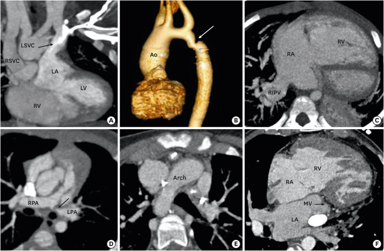
DORV is usually associated with multiple cardiac anomalies. The anomalous origin and course of coronary arteries are frequently noted. Looking from above, the coronary orifices rotate clockwise in DORV; the right coronary artery arises from the posterior- facing sinus and the left main trunk arises from the anterior-facing sinus. In addition, various types of anomalous courses may be seen. It is important to identify these anomalous courses of coronary arteries as any unidentified coronary anomaly may lead to disaster during surgery. Multiple other cardiac and extracardiac concomitant anomalies can be seen related to the aorta (right-sided arch, coarctation of aorta), pulmonary artery (pulmonary artery stenosis, atresia), pulmonary veins (partial or total anomalous pulmonary venous return), systemic veins (left-sided superior vena cava, interrupted inferior vena cava and azygous continuation), and thoracoabdominal system (bronchogenic cyst and diaphragmatic hernia) (Figure 10).56)
Figure 10. Associated cardiac anomalies. (A) A coronal CT image demonstrating LSVC draining into left atrium. (B) VRT image showing coarctation of the aorta. (C) Am axial CT image showing partial anomalous pulmonary venous return. The right inferior pulmonary vein is draining into right atria. The right atria and ventricle are dilated. (D) An oblique reformatted CT image showing stenosis of the osteoproximal part of the left pulmonary artery. (E) An axial CT image showing right-sided aortic arch. (F) An axial CT image shows mitral atresia.
Ao: aorta, CT: computed tomography, LA: left atrium, LPA: left pulmonary artery, LSVC: left-sided superior vena cava, LV: left ventricle, MV: mitral valve, PA: pulmonary artery, RA: right atrium, RV: right ventricle, RIPV: right inferior pulmonary vein, RPA: right pulmonary artery, RSVC: right-sided superior vena cava, RV: right ventricle, VRT: volume rendering technique, VSD: ventricular septal defect.
SURGICAL TREATMENT AND COMPLICATIONS
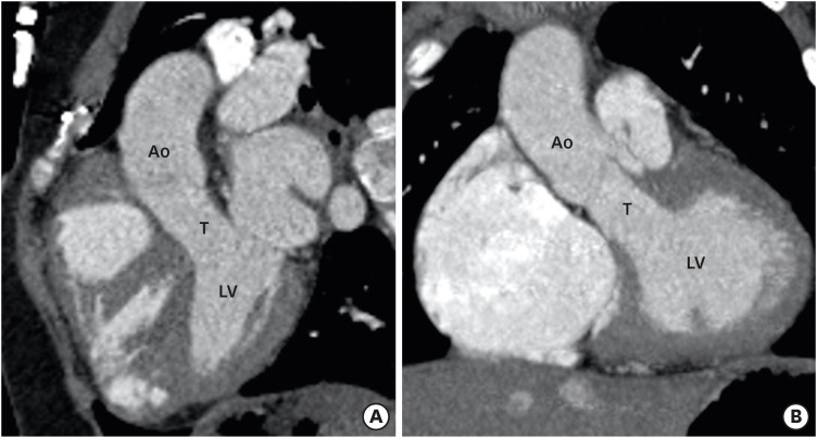
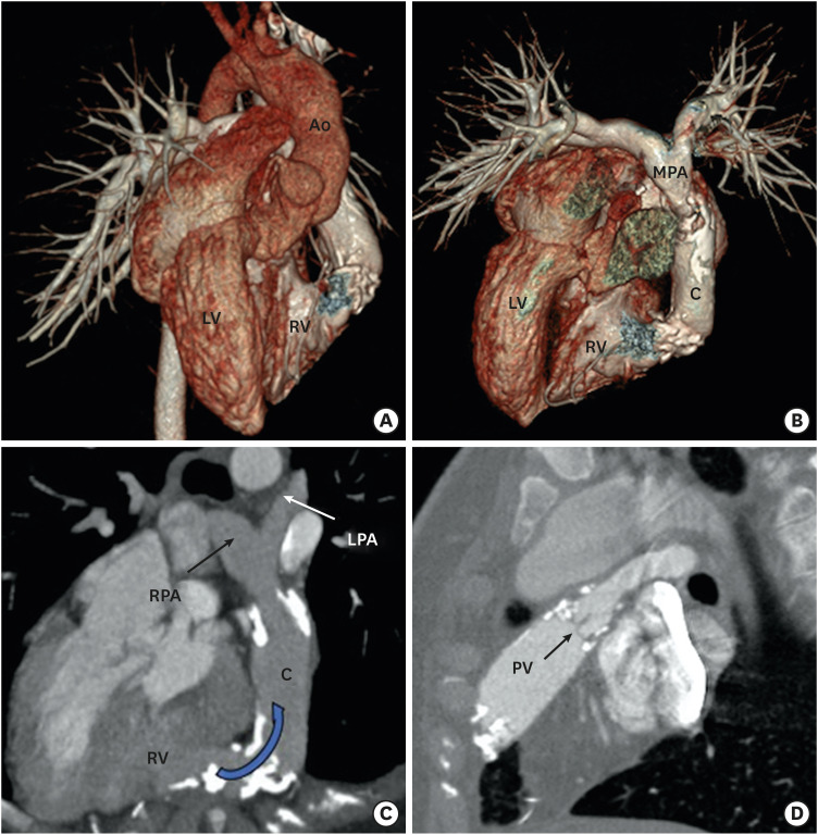
The surgical approach varies with the type of DORV. DORV with subaortic or doubly committed VSD without PS is treated by intraventricular tunnel repair between LV and aorta (Figure 11). Post-operative complications of this procedure are rare and include residual VSDs and subaortic obstructions (tunnel or non-tunnel-related).51) A TOF-type DORV with subaortic VSD and PS is treated like TOF, except the VSD closure is done by creating a tunnel rather than VSD patch. Common postoperative complications include residual VSD and residual or recurrent pulmonary artery stenosis.1),57) If the branch pulmonary arteries are severely hypoplastic then the preferred treatment method include early palliative systemic-pulmonary artery shunting followed by definitive repair later in the life. The Rastelli procedure is another option in this condition. In Rastelli procedure, the VSD is tunnelled to the aorta and an extracardiac conduit is placed between the RV and main pulmonary artery. Common postoperative complications of Rastelli procedure could be conduit-related (stenosis, calcification, kinking. and aneurysm), tunnel-related (stenosis, leakage, and obstruction), branch pulmonary artery stenosis, and biventricular dysfunction.1) Multiple approaches have been used for TGA-type DORVs with subpulmonic VSD (Taussig-Bing anomaly): (1) tunneling of VSD to the pulmonary artery with atrial switch; (2) tunneling of the VSD to the pulmonary artery with arterial switch; and (3) tunneling of the VSD to the pulmonary artery, aortopulmonary connection (Damus-Kaye-Stansel procedure), and extracardiac conduit between the RV and pulmonary artery. Complications of these procedures could be conduit- or tunnel-related as described above.1),58) A non-committed VSD presents the greatest challenge due to its remote location. In majority of the patients with remote VSD, the LV can be baffled to the aorta. If the anatomy allows rerouting of the VSD to the pulmonary artery, that is it performed along with arterial switch.59) If neither aortic nor pulmonary routing of the VSD is possible and there is concomitant PS, a systemic-to-pulmonary artery shunt (Blalock-Taussig shunt) is made to alleviate cyanosis. This is followed by bidirectional cavopulmonary anastomosis (a Glenn shunt) at the age of 6 months, and completion of the cavopulmonary connection at the age of 1 to 2 years.60)
Figure 11. Postoperative appearance of DORV. Sagittal (A) and coronal (B) reformatted CT angiography images demonstrating intraventricular tunnel created to channel blood flow from the LV to the aorta through ventricular septal defect. No evidence of any stenosis seen.
Ao: aorta, CT: computed tomography, DORV: double-outlet right ventricle, LV: left ventricle, T: tunnel.
ROLE OF CT ANGIOGRAPHY IN POSTOPERATIVE IMAGING
Magnetic resonance imaging is routinely used for postoperative assessment of DORV. CT is a good substitute due to widespread availability, low cost, rapid scanning, and especially when CMR is contraindicated. CT can be used to assess both palliative and corrective surgeries performed in DORV. It can reliably diagnose various postoperative complications related to a VSD (residual), intraventricular tunnel (stenosis, leak, aneurysm), conduit (calcification, stenosis, thrombosis), outflow tracts (RVOT obstruction, LVOT obstruction), pulmonary arteries (stenosis, aneurysm), aorta (coarctation and recoarctation), and ventricles (ventricular failure) (Figures 12-14). An ECG-gated scan can assess ventricular functions and provides detailed volumetric analysis, which can predict imminent ventricular failure. Volume rendering can reveal the extracardiac conduit or pathway. The imaging protocol in postoperative assessment should be tailored to the type of surgical repair. A brief description of surgical procedures and postoperative complications is provided in Table 1.
Figure 12. Postoperative appearance of DORV. (A) Coronal reformatted CT angiography image indicating an intraventricular tunnel to channel blood flow from the LV to the aorta through the ventricular septal defect. No evidence of any stenosis is visible. Oblique (B) and sagittal (C) CT angiography images indicating pulmonary stenosis with bulging of the RVOT, suggesting an RVOT aneurysm. The RV is dilated.
Ao: aorta, CT: computed tomography, DORV: double-outlet right ventricle, LV: left ventricle, PA: pulmonary artery, RV: right ventricle, RVOT: right ventricular outflow tract, T: tunnel.
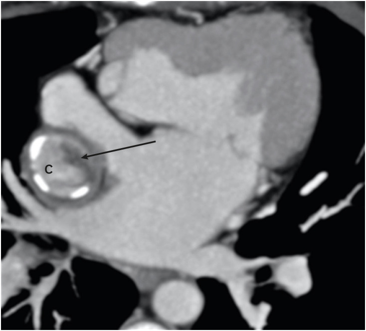
Figure 14. Postoperative (Fontan repair) appearance in a DORV. An axial MIP image showing eccentric hypodensity in an extra-atrial Fontan conduit that persists in a delayed venous phase, suggesting thrombosis (arrow).
C: conduit, DORV: double-outlet right ventricle, MIP: maximum intensity projection.
Table 1. Different types of surgical procedures performed in DORV and their post-operative complications.
| Type of VSD | Surgery | Postoperative complications |
|---|---|---|
| Subaortic or doubly committed VSD without PS | • Intraventricular tunnel repair (Gore-Tex fabric patch is used as a baffle to direct blood flow from LV through the VSD to the aorta). | • Residual VSD |
| • Tunnel related (stenosis, leakage, and obstruction) | ||
| Subaortic VSD with PS | • Definitive repair possible – LV is directed to aorta via intraventricular tunnel, Patch augmentation of PS is done. | • Residual VSD |
| • Definitive repair not possible – Palliative systemic to pulmonary shunt is made (BT shunt) followed by definitive repair later in life. | • Tunnel-related (stenosis, leakage and obstruction) | |
| • Rastelli procedure (VSD is tunnelled to aorta and an extracardiac conduit is placed between RV and main pulmonary artery). | • Pulmonary artery (residual stenosis, recurrent stenosis) | |
| • BT shunt (thrombosis, pseudoaneurysm) | ||
| • Conduit-related (stenosis, calcification, kinking and aneurysm) | ||
| • Tunnel-related (stenosis, leakage and obstruction) | ||
| • Branch pulmonary artery stenosis | ||
| • Biventricular dysfunction | ||
| Subpulmonic VSD without PS | • Tunneling of VSD to pulmonary artery with atrial switch. | • Tunnel-related (stenosis, leakage, and obstruction) |
| • Tunneling of VSD to pulmonary artery with arterial switch. | • Central or branch pulmonary artery stenosis | |
| • Tunneling of VSD to pulmonary artery, aortopulmonary connection (Damus-Kaye-Stansel procedure) and extracardiac conduit from RV to pulmonary artery. | • Baffle-related (stenosis, leakage, and obstruction) | |
| • Tunnel-related (stenosis, leakage, and obstruction) | ||
| • Central or branch pulmonary artery stenosis | ||
| • Tunnel-related (stenosis, leakage, and obstruction) | ||
| • Conduit-related (stenosis, calcification, kinking, and aneurysm) | ||
| • Systemic ventricular outflow tract obstruction | ||
| Remote VSD | • Enlargement of VSD (if restrictive) and tunnelled to aorta. | • Tunnel-related (stenosis, leakage, and obstruction) |
| • Tunneling of VSD to pulmonary artery with arterial switch. | • Tunnel related (stenosis, leakage, and obstruction) | |
| • Systemic to pulmonary artery shunt (Blalock-Taussig shunt) to alleviate cyanosis followed by bidirectional cavopulmonary anastomosis (Glenn shunt) at the age of 6 months, and completion of cavopulmonary connection at the age of 1 to 2 years. | • Central or branch pulmonary artery stenosis | |
| • Conduit related (stenosis, calcification, and thrombosis) | ||
| • Aortopulmonary collaterals | ||
| • Venovenous collaterals (between systemic veins and pulmonary veins) | ||
| • Pulmonary arteriovenous malformations | ||
| • Extracardiac (cirrhosis, liver nodules, protein-losing enteropathy, and plastic bronchitis) |
BT: Blalock-Taussig, DORV: double-outlet right ventricle, LV: left ventricle, PS: pulmonary stenosis, RV: right ventricle, VSD: ventricular septal defect.
Figure 13. Postoperative (Rastelli operation) appearance in a case of a DORV with cc-TGA. VRT image (A) and VRT image after removing Ao (B) showing cc-TGA morphology. The aorta is arising from right-sided LV. The RV is on the left side. A conduit is seen between the left-sided RV and the MPA. (C) An oblique reformatted MIP CT image showing dense calcification with moderate stenosis at the RV anastomotic site of the conduit. (D) An oblique reformatted CT image showing native pulmonary valve in the closed position. Mild calcification of the pulmonary valve leaflets is also seen.
Ao: aorta, C: conduit, cc-TGA: congenitally corrected transposition of the great artery, CT: computed tomography, DORV: double-outlet right ventricle, LPA: left pulmonary artery, MIP: maximum intensity projection, MPA: main pulmonary artery, RV: right ventricle, LV: left ventricle, PV: pulmonary valve, RPA: right pulmonary artery, VRT: volume rendering technique.
CONCLUSION
DORV often presents with complex and unique geometry. Cardiac CT imaging provides both morphological and functional information about DORV which is decisive in the patient’s management. CT is steadily becoming an invaluable imaging modality to fill the gap among echocardiography, cardiac MRI and cardiac catheterization. The unbeatable advantages of CT due to recent technological advancements have made it a very helpful tool in preoperative planning and postoperative follow-up.
ACKNOWLEDGEMENT
Special thanks to out CT technicians Varghese Philip and Shane Alam for the technical support.
Footnotes
Conflict of Interest: The authors have no financial conflicts of interest.
- Conceptualization: Kumar P.
- Methodology: Kumar P.
- Visualization: Kumar P.
- Writing - original draft: Kumar P.
- Writing - review & editing: Bhatia M.
References
- 1.Walters HL, 3rd, Mavroudis C, Tchervenkov CI, Jacobs JP, Lacour-Gayet F, Jacobs ML. Congenital Heart Surgery Nomenclature and Database Project: double outlet right ventricle. Ann Thorac Surg. 2000;69:S249–63. doi: 10.1016/s0003-4975(99)01247-3. [DOI] [PubMed] [Google Scholar]
- 2.Smallhorn JF. Double-outlet right ventricle: an echocardiographic approach. Semin Thorac Cardiovasc Surg Pediatr Card Surg Annu. 2000;3:20–33. doi: 10.1053/tc.2000.6041. [DOI] [PubMed] [Google Scholar]
- 3.Elster A. Impact of new technologies on dose reduction in CT. In: Osborn AG, Abbara S, Elster AD, et al., editors. Yearbook of Diagnostic Radiology. St. Louis, MO: Mosby; 2011. pp. 191–192. [DOI] [Google Scholar]
- 4.Lacour-Gayet F, Haun C, Ntalakoura K, et al. Biventricular repair of double outlet right ventricle with non-committed ventricular septal defect (VSD) by VSD rerouting to the pulmonary artery and arterial switch. Eur J Cardiothorac Surg. 2002;21:1042–1048. doi: 10.1016/s1010-7940(02)00105-7. [DOI] [PubMed] [Google Scholar]
- 5.Sridaromont S, Feldt RH, Ritter DG, Davis GD, Edwards JE. Double outlet right ventricle: hemodynamic and anatomic correlations. Am J Cardiol. 1976;38:85–94. doi: 10.1016/0002-9149(76)90067-9. [DOI] [PubMed] [Google Scholar]
- 6.Bashore TM. Adult congenital heart disease: right ventricular outflow tract lesions. Circulation. 2007;115:1933–1947. doi: 10.1161/CIRCULATIONAHA.105.592345. [DOI] [PubMed] [Google Scholar]
- 7.Bajolle F, Zaffran S, Kelly RG, et al. Rotation of the myocardial wall of the outflow tract is implicated in the normal positioning of the great arteries. Circ Res. 2006;98:421–428. doi: 10.1161/01.RES.0000202800.85341.6e. [DOI] [PubMed] [Google Scholar]
- 8.Gibson DG. Diagnosis of double outlet right ventricle (DORV) by M-mode echocardiography. In: Longmore DB, editor. Modern Cardiac Surgery. Dordrecht: Springer; 1978. pp. 361–364. [DOI] [Google Scholar]
- 9.Bharucha T, Hlavacek AM, Spicer DE, Theocharis P, Anderson RH. How should we diagnose and differentiate hearts with double-outlet right ventricle? Cardiol Young. 2017;27:1–15. doi: 10.1017/S1047951116001190. [DOI] [PubMed] [Google Scholar]
- 10.Pacileo G, Di Salvo G, Limongelli G, Miele T, Calabrò R. Echocardiography in congenital heart disease: usefulness, limits and new techniques. J Cardiovasc Med (Hagerstown) 2007;8:17–22. doi: 10.2459/01.JCM.0000247430.36581.c2. [DOI] [PubMed] [Google Scholar]
- 11.Ntsinjana HN, Hughes ML, Taylor AM. The role of cardiovascular magnetic resonance in pediatric congenital heart disease. J Cardiovasc Magn Reson. 2011;13:51. doi: 10.1186/1532-429X-13-51. [DOI] [PMC free article] [PubMed] [Google Scholar]
- 12.Tsai-Goodman B, Geva T, Odegard KC, Sena LM, Powell AJ. Clinical role, accuracy, and technical aspects of cardiovascular magnetic resonance imaging in infants. Am J Cardiol. 2004;94:69–74. doi: 10.1016/j.amjcard.2004.03.033. [DOI] [PubMed] [Google Scholar]
- 13.European Society of Cardiology (ESC); European Heart Rhythm Association (EHRA) Brignole M, et al. 2013 ESC guidelines on cardiac pacing and cardiac resynchronization therapy: the task force on cardiac pacing and resynchronization therapy of the European Society of Cardiology (ESC). Developed in collaboration with the European Heart Rhythm Association (EHRA) Europace. 2013;15:1070–1118. doi: 10.1093/europace/eut206. [DOI] [PubMed] [Google Scholar]
- 14.Olchowy C, Cebulski K, Łasecki M, et al. The presence of the gadolinium-based contrast agent depositions in the brain and symptoms of gadolinium neurotoxicity - a systematic review. PLoS One. 2017;12:e0171704. doi: 10.1371/journal.pone.0171704. [DOI] [PMC free article] [PubMed] [Google Scholar]
- 15.U.S. Food and Drug Administration. FDA Drug Safety Communication: FDA warns that gadolinium-based contrast agents (GBCAs) are retained in the body; requires new class warnings. [Accessed January 15, 2019]. Available at: https://www.fda.gov/Drugs/DrugSafety/ucm589213.htm.
- 16.Feltes TF, Bacha E, Beekman RH, 3rd, et al. Indications for cardiac catheterization and intervention in pediatric cardiac disease: a scientific statement from the American Heart Association. Circulation. 2011;123:2607–2652. doi: 10.1161/CIR.0b013e31821b1f10. [DOI] [PubMed] [Google Scholar]
- 17.Moustafa GA, Kolokythas A, Charitakis K, Avgerinos DV. Diagnostic cardiac catheterization in the pediatric population. Curr Cardiol Rev. 2016;12:155–162. doi: 10.2174/1573403X12666160301120955. [DOI] [PMC free article] [PubMed] [Google Scholar]
- 18.Al-Mousily F, Shifrin RY, Fricker FJ, Feranec N, Quinn NS, Chandran A. Use of 320-detector computed tomographic angiography for infants and young children with congenital heart disease. Pediatr Cardiol. 2011;32:426–432. doi: 10.1007/s00246-010-9873-8. [DOI] [PubMed] [Google Scholar]
- 19.Lell M, Marwan M, Schepis T, et al. Prospectively ECG-triggered high-pitch spiral acquisition for coronary CT angiography using dual source CT: technique and initial experience. Eur Radiol. 2009;19:2576–2583. doi: 10.1007/s00330-009-1558-4. [DOI] [PubMed] [Google Scholar]
- 20.Chan FP. MR and CT imaging of the pediatric patient with structural heart disease. Semin Thorac Cardiovasc Surg Pediatr Card Surg Annu. 2009;12:99–105. doi: 10.1053/j.pcsu.2009.01.009. [DOI] [PubMed] [Google Scholar]
- 21.Vukicevic M, Mosadegh B, Min JK, Little SH. Cardiac 3D printing and its future directions. JACC Cardiovasc Imaging. 2017;10:171–184. doi: 10.1016/j.jcmg.2016.12.001. [DOI] [PMC free article] [PubMed] [Google Scholar]
- 22.Siripornpitak S, Pornkul R, Khowsathit P, Layangool T, Promphan W, Pongpanich B. Cardiac CT angiography in children with congenital heart disease. Eur J Radiol. 2013;82:1067–1082. doi: 10.1016/j.ejrad.2011.11.042. [DOI] [PubMed] [Google Scholar]
- 23.Lin E, Alessio A. What are the basic concepts of temporal, contrast, and spatial resolution in cardiac CT? J Cardiovasc Comput Tomogr. 2009;3:403–408. doi: 10.1016/j.jcct.2009.07.003. [DOI] [PMC free article] [PubMed] [Google Scholar]
- 24.Hellinger JC, Pena A, Poon M, Chan FP, Epelman M. Pediatric computed tomographic angiography: imaging the cardiovascular system gently. Radiol Clin North Am. 2010;48:439–467. doi: 10.1016/j.rcl.2010.03.005. [DOI] [PubMed] [Google Scholar]
- 25.Krishnamurthy R. Neonatal cardiac imaging. Pediatr Radiol. 2010;40:518–527. doi: 10.1007/s00247-010-1549-2. [DOI] [PubMed] [Google Scholar]
- 26.Han BK, Rigsby CK, Leipsic J, et al. Computed tomography imaging in patients with congenital heart disease, Part 2: Technical recommendations. An expert consensus document of the Society of Cardiovascular Computed Tomography (SCCT): Endorsed by the Society of Pediatric Radiology (SPR) and the North American Society of Cardiac Imaging (NASCI) J Cardiovasc Comput Tomogr. 2015;9:493–513. doi: 10.1016/j.jcct.2015.07.007. [DOI] [PubMed] [Google Scholar]
- 27.Booij R, Dijkshoorn ML, van Straten M, et al. Cardiovascular imaging in pediatric patients using dual source CT. J Cardiovasc Comput Tomogr. 2016;10:13–21. doi: 10.1016/j.jcct.2015.10.003. [DOI] [PubMed] [Google Scholar]
- 28.Motonaga KS, Khairy P, Dubin AM. Electrophysiologic therapeutics in heart failure in adult congenital heart disease. Heart Fail Clin. 2014;10:69–89. doi: 10.1016/j.hfc.2013.09.011. [DOI] [PubMed] [Google Scholar]
- 29.Mondésert B, Khairy P. Implantable cardioverter-defibrillators in congenital heart disease. Curr Opin Cardiol. 2014;29:45–52. doi: 10.1097/HCO.0000000000000019. [DOI] [PubMed] [Google Scholar]
- 30.Kliger C, Eiros R, Isasti G, et al. Review of surgical prosthetic paravalvular leaks: diagnosis and catheter-based closure. Eur Heart J. 2013;34:638–649. doi: 10.1093/eurheartj/ehs347. [DOI] [PubMed] [Google Scholar]
- 31.Habets J, Symersky P, van Herwerden LA, et al. Prosthetic heart valve assessment with multidetector-row CT: imaging characteristics of 91 valves in 83 patients. Eur Radiol. 2011;21:1390–1396. doi: 10.1007/s00330-011-2068-8. [DOI] [PMC free article] [PubMed] [Google Scholar]
- 32.Szymczyk K, Moll M, Sobczak-Budlewska K, et al. Usefulness of routine coronary CT angiography in patients with transposition of the great arteries after an arterial switch operation. Pediatr Cardiol. 2018;39:335–346. doi: 10.1007/s00246-017-1761-z. [DOI] [PMC free article] [PubMed] [Google Scholar]
- 33.Cheng Z, Wang X, Duan Y, et al. Low-dose prospective ECG-triggering dual-source CT angiography in infants and children with complex congenital heart disease: first experience. Eur Radiol. 2010;20:2503–2511. doi: 10.1007/s00330-010-1822-7. [DOI] [PubMed] [Google Scholar]
- 34.Rigsby CK, McKenney SE, Hill KD, et al. Radiation dose management for pediatric cardiac computed tomography: a report from the Image Gently ‘Have-A-Heart’ campaign. Pediatr Radiol. 2018;48:5–20. doi: 10.1007/s00247-017-3991-x. [DOI] [PMC free article] [PubMed] [Google Scholar]
- 35.Ghoshhajra BB, Lee AM, Engel LC, et al. Radiation dose reduction in pediatric cardiac computed tomography: experience from a tertiary medical center. Pediatr Cardiol. 2014;35:171–179. doi: 10.1007/s00246-013-0758-5. [DOI] [PubMed] [Google Scholar]
- 36.Hedgire SS, Baliyan V, Ghoshhajra BB, Kalra MK. Recent advances in cardiac computed tomography dose reduction strategies: a review of scientific evidence and technical developments. J Med Imaging (Bellingham) 2017;4:031211. doi: 10.1117/1.JMI.4.3.031211. [DOI] [PMC free article] [PubMed] [Google Scholar]
- 37.Gao W, Zhong YM, Sun AM, et al. Diagnostic accuracy of sub-mSv prospective ECG-triggering cardiac CT in young infant with complex congenital heart disease. Int J Cardiovasc Imaging. 2016;32:991–998. doi: 10.1007/s10554-016-0854-8. [DOI] [PubMed] [Google Scholar]
- 38.Jin KN, Park EA, Shin CI, Lee W, Chung JW, Park JH. Retrospective versus prospective ECG-gated dual-source CT in pediatric patients with congenital heart diseases: comparison of image quality and radiation dose. Int J Cardiovasc Imaging. 2010;26(Suppl 1):63–73. doi: 10.1007/s10554-009-9579-2. [DOI] [PubMed] [Google Scholar]
- 39.Young C, Taylor AM, Owens CM. Paediatric cardiac computed tomography: a review of imaging techniques and radiation dose consideration. Eur Radiol. 2011;21:518–529. doi: 10.1007/s00330-010-2036-8. [DOI] [PubMed] [Google Scholar]
- 40.Paul JF, Rohnean A, Sigal-Cinqualbre A. Multidetector CT for congenital heart patients: what a paediatric radiologist should know. Pediatr Radiol. 2010;40:869–875. doi: 10.1007/s00247-010-1614-x. [DOI] [PubMed] [Google Scholar]
- 41.Rybicki FJ, Otero HJ, Steigner ML, et al. Initial evaluation of coronary images from 320-detector row computed tomography. Int J Cardiovasc Imaging. 2008;24:535–546. doi: 10.1007/s10554-008-9308-2. [DOI] [PubMed] [Google Scholar]
- 42.Yim D, Dragulescu A, Ide H, et al. Essential modifiers of double outlet right ventricle: revisit with endocardial surface images and 3-dimensional print models. Circ Cardiovasc Imaging. 2018;11:e006891. doi: 10.1161/CIRCIMAGING.117.006891. [DOI] [PubMed] [Google Scholar]
- 43.Garekar S, Bharati A, Chokhandre M, et al. Clinical application and multidisciplinary assessment of three dimensional printing in double outlet right ventricle with remote ventricular septal defect. World J Pediatr Congenit Heart Surg. 2016;7:344–350. doi: 10.1177/2150135116645604. [DOI] [PubMed] [Google Scholar]
- 44.Farooqi KM, Nielsen JC, Uppu SC, et al. Use of 3-dimensional printing to demonstrate complex intracardiac relationships in double-outlet right ventricle for surgical planning. Circ Cardiovasc Imaging. 2015;8:e003043. doi: 10.1161/CIRCIMAGING.114.003043. [DOI] [PubMed] [Google Scholar]
- 45.Kirklin JW, Barratt-Boyes BG. Double-outlet right ventricle. In: Kirklin JW, Barratt-Boyes BG, editors. Cardiac Surgery. 2nd ed. New York, NY: Churchill Livingston; 1993. pp. 1469–1500. [Google Scholar]
- 46.Musumeci F, Shumway S, Lincoln C, Anderson RH. Surgical treatment for double-outlet right ventricle at the Brompton Hospital, 1973 to 1986. J Thorac Cardiovasc Surg. 1988;96:278–287. [PubMed] [Google Scholar]
- 47.Mazzucco A, Faggian G, Stellin G, et al. Surgical management of double-outlet right ventricle. J Thorac Cardiovasc Surg. 1985;90:29–34. [PubMed] [Google Scholar]
- 48.Goldberg SP, McCanta AC, Campbell DN, et al. Implications of incising the ventricular septum in double outlet right ventricle and in the Ross-Konno operation. Eur J Cardiothorac Surg. 2009;35:589–593. doi: 10.1016/j.ejcts.2008.12.035. [DOI] [PMC free article] [PubMed] [Google Scholar]
- 49.Ebadi A, Spicer DE, Backer CL, Fricker FJ, Anderson RH. Double-outlet right ventricle revisited. J Thorac Cardiovasc Surg. 2017;154:598–604. doi: 10.1016/j.jtcvs.2017.03.049. [DOI] [PubMed] [Google Scholar]
- 50.Rosenquist GC, Clark EB, Sweeney LJ, McAllister HA. The normal spectrum of mitral and aortic valve discontinuity. Circulation. 1976;54:298–301. doi: 10.1161/01.cir.54.2.298. [DOI] [PubMed] [Google Scholar]
- 51.Russo P, Danielson GK, Puga FJ, McGoon DC, Humes R. Modified Fontan procedure for biventricular hearts with complex forms of double-outlet right ventricle. Circulation. 1988;78:III20–III25. [PubMed] [Google Scholar]
- 52.Hammon JW, Jr, Lupinetti FM, Maples MD, et al. Predictors of operative mortality in critical valvular aortic stenosis presenting in infancy. Ann Thorac Surg. 1988;45:537–540. doi: 10.1016/s0003-4975(10)64527-4. [DOI] [PubMed] [Google Scholar]
- 53.Edwards WD. Double-outlet right ventricle and tetralogy of Fallot. Two distinct but not mutually exclusive entities. J Thorac Cardiovasc Surg. 1981;82:418–422. [PubMed] [Google Scholar]
- 54.Taussig HB, Bing RJ. Complete transposition of the aorta and a levoposition of the pulmonary artery; clinical, physiological, and pathological findings. Am Heart J. 1949;37:551–559. doi: 10.1016/0002-8703(49)91133-3. [DOI] [PubMed] [Google Scholar]
- 55.Neufeld HN, Lucas RV, Jr, Lester RG, Adams P, Jr, Anderson RC, Edwards JE. Origin of both great vessels from the right ventricle without pulmonary stenosis. Br Heart J. 1962;24:393–408. doi: 10.1136/hrt.24.4.393. [DOI] [PMC free article] [PubMed] [Google Scholar]
- 56.Lapierre C, Déry J, Guérin R, Viremouneix L, Dubois J, Garel L. Segmental approach to imaging of congenital heart disease. Radiographics. 2010;30:397–411. doi: 10.1148/rg.302095112. [DOI] [PubMed] [Google Scholar]
- 57.Wetter J, Sinzobahamvya N, Blaschczok HC, et al. Results of arterial switch operation for primary total correction of the Taussig-Bing anomaly. Ann Thorac Surg. 2004;77:41–46. doi: 10.1016/s0003-4975(03)01134-2. [DOI] [PubMed] [Google Scholar]
- 58.Belli E, Serraf A, Lacour-Gayet F, et al. Surgical treatment of subaortic stenosis after biventricular repair of double-outlet right ventricle. J Thorac Cardiovasc Surg. 1996;112:1570–1578. doi: 10.1016/S0022-5223(96)70016-8. [DOI] [PubMed] [Google Scholar]
- 59.Lacour-Gayet F. Biventricular repair of double outlet right ventricle with noncommitted ventricular septal defect. Semin Thorac Cardiovasc Surg Pediatr Card Surg Annu. 2002;5:163–172. doi: 10.1053/pcsu.2002.31491. [DOI] [PubMed] [Google Scholar]
- 60.Ruzmetov M, Rodefeld MD, Turrentine MW, Brown JW. Rational approach to surgical management of complex forms of double outlet right ventricle with modified Fontan operation. Congenit Heart Dis. 2008;3:397–403. doi: 10.1111/j.1747-0803.2008.00220.x. [DOI] [PubMed] [Google Scholar]


