Abstract
This article briefly describes the event of a defective detector block in a daily quality assurance scan/blank scan and insists on implementing guidelines to scan or not to scan in such a scenario. The nuclear medicine physicist should have a clear understanding of the blank scan graph, which shall help rectify the right cause of problem and give confidence to the physician in reporting the acquired study. A routine blank scan in positron emission tomography signifies various parameters of the crystal (coincidence count rate, single count rate, dead time, and coincidence time along with energy response) and in some respect is analogous to the daily uniformity flood image for gamma cameras, providing an overall assessment of detector response. We encountered a bad detector block in our routine quality assurance scan/blank scan and analyzed the root cause behind such an error which was finally restored to normalcy by replacing the defected part with a new one and an error-free blank scan was established. The analysis was carried out by performing various possible checks and discussing the issue with service engineer to help identify the defects much before service engineer actually arrived in our department. This allowed us to take the correct decision and enabled us to get the scanner repaired faster. Hence, a good understanding of the daily quality control test and proper analysis of the same may result in swift decision-making and faster repair of equipment leading to minimal disruption in the clinical workflow as well as avoidance of suboptimal scanning leading to the wrong diagnosis.
Keywords: Block detectors, crystal map, photomultiplier tube tuning, positron emission tomography
Introduction
With the rapid growth of cancer worldwide, positron emission tomography (PET) has become a major tool for helping in cancer staging and response evaluation. This has put a greater responsibility on the Nuclear medicine physicist for obtaining accurate results from the system as he/she should be confident enough with the scanner's performance. Hence, a quality assurance program for the scanner should be established to ensure that the performance of a procedure or instrument is within a predefined acceptable range.[1,2,3,4] Second, a guideline should be established to follow in case of various errors encountered as it shall help in the smooth functioning of the department. It is the rationale that in a busy department, performing all possible quality assurance test might be difficult but there should be a minimum requirement for the daily quality assurance (DQA) scan/blank scan, to test the scanner under normal conditions and periodic recalibrations be carried out to guarantee correct normalization.[2,3] The DQA has unparalleled advantages as it is less time-consuming and can help in the evaluation of hardware-related artifact too.[5] It helps display in graphical representation various parameters of the crystal in PET (coincidence count rate, single count rate, dead time, coincidence time, and energy response). A PET system is made of an array of scintillation crystals, consisting of multiple blocks, and optically coupled to four or more single-anode photomultiplier tube (PMT) wherein a block damage of any scintillator can occur during the routine process without any warning. Hence, the knowledge of the malfunctioning block and its cause can be useful to prevent the cancellation of patients. Second, due to the quadrant sharing of PMT, the gain stability of all the PMT's is also a factor to be taken care of for the stable functioning of the system.[6] These defective detector blocks reading can cause serious image artifacts.[7] Some minor artifacts do not have a final impact on the diagnosis and can easily be recognized by an expert, but few artifacts may bring serious impacts on the image quality and finally lead to the wrong diagnosis.[8] One such case of defective crystal was observed in our department.
Case Report
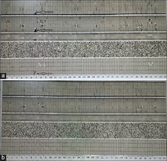
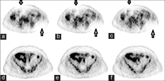
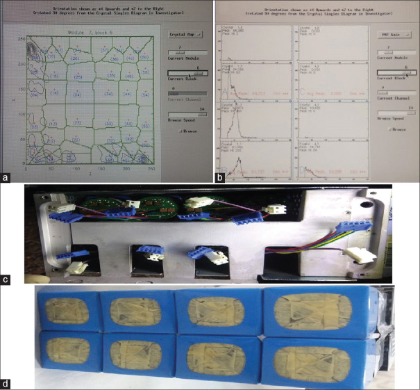
As per the routine practice, we were acquiring a DQA scan, with the inbuilt Ge-68 rod source of our PET-computed tomography (CT) scanner (Discovery STE, GE Medical System, USA) before injecting the patients with F18-Fluoro Deoxy Glucose for PET-CT study. On completion of the DQA scan, we observed a black spot at module 7 of block 6 [Figure 1a arrow mark]. From our previous experience; we could understand that it could be due to reasons such as malfunctioning of detector, temperature-humidity variation, or Cassette Electronic Module board (CEM board) error. We started analyzing each point to rule out the cause of a bad block detector. The temperature-humidity factor was ruled out as the gantry and console room temperature and humidity were well within the prescribed limit (20°C ± 2°C; 45 ± 5%) and stable for quite a few days, neither was there any error in the CEM board because an error in CEM board causes malfunctioning of a whole module and not a single block of a module. Hence, we shifted our analysis to detector malfunctioning, which could have been due to a nonfunctional detector or having a substantial lower sensitivity than that of the other detectors.[7,8] We looked up the two-dimensional (2D) generated crystal decoding map of module 7, block 6. It clearly showed the distorted map with uneven/loss of distribution of signal [Figure 2a]. Meanwhile, we contacted a service engineer and briefed the situation and discussed with him. This prompted us to proceed further for analyzing the PMT gain/peak of the supporting module's block. The peak was completely derailed; which was leading to poor outcomes of the detector block [Figure 2b]. We discussed the outcome of PMT gain with service engineer and concluded the problem in one of the PMT in the 7th module. Service engineer ordered the detector module from a nearby warehouse. We also discussed this issue with our Nuclear medicine physician to decide whether to inject patients or not under such a situation. After the discussion, we performed a dummy scan to see whether the system was generating raw data for both attenuation correction and nonattenuation correction files and whether the fusion was taking place with the selected CT data. On its assurance, we along with the Nuclear medicine physician reanalyzed the DQA graph and since the region of a defect was confined to < 1% of total crystals, we decided to proceed ahead with selected routine PET-CT studies where accuracy in standardized uptake value (SUV) quantification was not really mandatory as per Nuclear medicine physician and rescheduled the cases in which SUV quantification was of prime importance: Like early response evaluation after therapy and at the same time registered a service call as per departmental protocol to GE service support. The images acquired were clearly interpretable with minimal degradation in the qualitative analysis [Figure 3a–c arrow mark]. By the time, we completed a study of selected few patients the service engineer arrived. After scrutinizing thoroughly through the software and error log along with inspection of completed studies and internal components/hardware, we again proceeded first with system calibration, which makes coarse and fine gain adjustments to the PMT, but we had the same graph of DQA.[11] Late in the evening part ordered also arrived and replaced it successfully in the early morning the next day. The detector module is shown in Figure 2c and d. On installation and updating the PMT gain, we performed the DQA scan. On review by the service engineer and physicist in the department, DQA was found to be normal [Figure 1b]. On complete satisfaction, we performed a clinical PET-CT study successfully and there were no artifacts in the PET images [Figure 3d–f].
Figure 1.

Daily Quality assurance graph, (a) Shows defective graph arrow sign (b) shows a normal graph
Figure 2.
Detailed graph at module level; (a) graph shows loss of signal on two-dimensional generated crystal decoding map of module 7, block 6, (b) graph shows loss of signal in energy peaking map of module 7, block 6, (c) figure shows the upper part of the detector module, and (d) figure shows the lower part of a detector module
Figure 3.

Clinical scan with a defective module and after replacement; (a-c) arrows show photo deficient area on a clinical scan performed with defective detectors. (d-f) No photo de-ficient area in the clinical image performed after replacement of the detector module
Discussion
Our system is a 35 (0–34) module Bismuth Germanate BGO crystal PET system, with each module having 8 blocks (0to7), wherein each block is having 6 rows (0–5) and 8 columns (0–7) of crystals, making a total array of 13,440 crystals (35 × 8 × 48). This array of a crystal is optically coupled to eight single-anodes PMT as shown in Figure 2c. The decoding of crystal position relies highly on the relative gain stability of all the PMT. Any drift in gain of single PMT relative to other can cause distortion in 2D crystal encoding map and assign wrong crystal of a gamma hit.[12] Various factors can lead to PMT tube gain change, such as room temperature, patient load, short term or long-term radiation exposure, and time, leading to degraded image resolution and quality in a PET camera. It has been observed that long-term PMT gain drop is not due to temperature, but due to the usage (light load) of the PMT, second, a short-term drift could be caused by idling of camera for 1–3 days, which can temporarily desensitize its PMT by 3%–12%, but a higher radiation load for the camera, especially after a few days of Idling can de-sensitze its PMT by 4%–17%.[12] A long-term variation could be recovered by system-wide tuning every few weeks or months in current commercial PET cameras, but it cannot overcome short-term variation. In our case, we faced the error in the middle of the week, hence the short-term drift was ruled out and the only factor which could lead to PMT drift was its long usage and routine wear and tear. Earlier too such a scenario has been experienced by the various users of modality, wherein. One of the studies performed by ElHami et al. has shown a mean change in phantom SUV max was-2%(range,-6% to + 3%) in the presence of a single defective block detector and-3% (range,-11% to + 7%) in the presence of two defective block detectors respectively. Moreover, the routine patients scan could be performed keeping the reading physician aware of the detector failure.[13] Second study performed by Samiee et al. have concluded that for the case of one to two defective detectors in a system, reasonably quantitative clinical PET imaging can be performed and it might be possible to acquire useable images.[14] Zito et al., in their study, they demonstrated that nonuniformity parameters did not significantly change whenever assessed on original or an altered data having one block or two axial blocks (faulty analog board) with zero sensitivity.[15] In other study Jha et al. have shown the reduction of artifacts using the sinogram correction technique.[16] We were partly lucky to have the error confine to single-crystal block, avoiding the complete breakdown of the system, second a good understanding of the internal components and established guideline/flow chart to investigate the outcome of each part through its graphical representation can help us conclude to diagnose the right cause/origin of error much earlier than the arrival of service engineer. Such practice guidelines of understanding the cause and taking the decision in consensus with the reporting physician being aware of the current scenario and its limitation can help plan patients accordingly for optimal utilization of the modality in such scenarios and reduce the turnaround time to breakdown.
Conclusion
Good understanding of the DQA test by qualified nuclear medicine physicist and proper analysis of the same may result in swift decision-making and faster repair of equipment leading to minimal disruption in the clinical work as well as avoidance of suboptimal scanning leading to the wrong diagnosis.
Financial support and sponsorship
Nil.
Conflicts of interest
There are no conflicts of interest.
References
- 1.Zanzonico P. Routine quality control of clinical nuclear medicine instrumentation: A brief review. J Nucl Med. 2008;49:1114–31. doi: 10.2967/jnumed.107.050203. [DOI] [PMC free article] [PubMed] [Google Scholar]
- 2.Keim P. An overview of PET quality assurance procedures: Part 1. J Nucl Med Technol. 1994;22:27–34. [Google Scholar]
- 3.Jha AK, Mithun S, Singh AM, Purandare NC, Shah S, Agrawal A, et al. 18-Month performance assessment of gemini TF 16 PET/CT system in a high-volume department. J Nucl Med Technol. 2016;44:36–41. doi: 10.2967/jnmt.115.168492. [DOI] [PubMed] [Google Scholar]
- 4.Jha AK, Mithun S, Puranik AD, Purandare NC, Shah S, Agrawal A, et al. Performance characteristic evaluation of a bismuth germanate-based high-sensitivity 5-ring discovery image quality positron emission tomography/computed tomography system as per National Electrical Manufacturers Association NU 2-2012. World J Nucl Med. 2019;18:351–60. doi: 10.4103/wjnm.WJNM_72_18. [DOI] [PMC free article] [PubMed] [Google Scholar]
- 5.Tayal S, Gandhi AC, Ali A. Significance of daily quality assurance scan in hardware artifact evaluation. Indian J Nucl Med. 2018;33:351–4. doi: 10.4103/ijnm.IJNM_70_18. [DOI] [PMC free article] [PubMed] [Google Scholar]
- 6.Li H, Liu Y, Xing T, Wang Y, Uribe J, Baghaei H, et al. An instantaneous photomultiplier tube gain-tuning method for PET or gamma camera detectors using an LED network. IEEE Trans Nucl Sci. 2005;52:1295–9. [Google Scholar]
- 7.Buchert R, Bohuslavizki KH, Mester J, Clausen M. Quality assurance in PET: Evaluation of the clinical relevance of detector defects. J Nucl Med. 1999;40:1657–65. [PubMed] [Google Scholar]
- 8.Hsieh J. Image artifacts: Appearances, causes and corrections. In: Computed Tomography: Principles, Design, Artifacts and Recent Advances. Bellingham, Wash: SPIE Press; 2003. pp. 167–240. [Google Scholar]
- 9.Cherry SR, Sorenson J, Phelps ME, Methé BM. Physics in Nuclear Medicine. Vol. 31, Med Phys. 2004;31:2370–71. [Google Scholar]
- 10.Zanzonico P. Positron emission tomography: A review of basic principles, scanner design and performance, and current systems. Semin Nucl Med. 2004;34:87–111. doi: 10.1053/j.semnuclmed.2003.12.002. [DOI] [PubMed] [Google Scholar]
- 11.Keim P. An overview of PET quality assurance procedures: Part 2. J Nucl Med Technol. 1994;22:27–34. [Google Scholar]
- 12.Uribe J, Li H, Baghaei H, Aykac M, Wang Y, Liu Y, et al. Effect of photomultiplier gain-drift and radiation exposure on 2D-map decoding of detector arrays used in positron emission tomography. IEEE Nucl Sci Symp Med Imaging Conf. 2002;4:1960–4. [Google Scholar]
- 13.Elhami E, Samiee M, Demeter S, Leslie WD, Goertzen AL. On the significance of defective block detectors in clinical (18) F-FDG PET/CT imaging. Mol Imaging Biol. 2011;13:265–74. doi: 10.1007/s11307-010-0362-5. [DOI] [PubMed] [Google Scholar]
- 14.Samiee, Maryam, Goertzen A. L. “Quantifying the effects of defective block detectors in a 3D whole body pet camera.” 2007 IEEE Nuclear Science Symposium Conference Record 6 (2007): 4258-4261 [Google Scholar]
- 15.Zito F, De Bernardi E, Schiavini M, Canzi C, Voltini F, Agosteo S, et al. Analysis of different detector and electronics defects on F18-FDG images. Nucl Instrum Meth A. 2007;571:493–7. [Google Scholar]
- 16.Jha AK, Purandare NC, Shah S, Agrawal A, Puranik AD, Rangarajan V. PET reconstruction artifact can be minimized by using sinogram correction and filtered back-projection technique. Indian J Radiol Imaging. 2014;24:103–6. doi: 10.4103/0971-3026.134379. [DOI] [PMC free article] [PubMed] [Google Scholar]


