Abstract
The mechanical thrombectomy (MT) efficacy, for large vessel occlusion (LVO) treatment in patients with stroke, could be improved if better teaching and practicing surgical tools were available. We propose a novel approach that uses 3D printing (3DP) to generate patient anatomical vascular variants for simulation of diverse clinical scenarios of LVO treated with MT. 3DP phantoms were connected to a flow loop with physiologically relevant flow conditions, including input flow rate and fluid temperature. A simulated blood clot was introduced into the model and placed in the Middle Cerebral Artery region. Clot location, composition (hard or soft clot), length, and arterial angulation were varied and MTs were simulated using stent retrievers. Device placement relative to the clot and the outcome of the thrombectomy were recorded for each situation. Angiograms were captured before and after LVO simulation and after the MT. Recanalization outcome was evaluated using the Thrombolysis in Cerebral Infarction (TICI) scale. Forty-two 3DP neurovascular phantom benchtop experiments were performed. Clot mechanical properties, hard versus soft, had the highest impact on the MT outcome, with 18/42 proving to be successful with full or partial clot retrieval. Other factors such as device manufacturer and the tortuosity of the 3DP model correlated weakly with the MT outcome. We demonstrated that 3DP can become a comprehensive tool for teaching and practicing various surgical procedures for MT in LVO patients. This platform can help vascular surgeons understand the endovascular devices limitations and patient vascular geometry challenges, to allow surgical approach optimization.
Keywords: stent retriever thrombectomy, ischemic stroke, large vessel occlusion, thrombolysis in cerebral infarction (TICI)
1. Description of Purpose
795,000 people experience a stroke in the United States annually with 87% of these strokes being ischemic in nature. Often the cause of these strokes are a lack of blood flow due to an arterial occlusion in need of endovascular revascularization of large vessel occlusion (LVO) using stent retriever mechanical thrombectomy (MT)[1, 2]. Once a stent is deployed at the occlusion site, the clot becomes entrapped within the wiring of the device allowing for the stent and the clot to be withdrawn from the patient anatomy as a single unit. Stent retriever thrombectomy is currently recommended in patients with acute ischemic stroke (AIS) from LVO. The success of thrombectomy is graded using Thrombolysis in Cerebral Infarction (TICI) scale which ranges from 0 (no recanalization) to 3 (complete recanalization). Recanalization is the main factor that determines whether the treatment method of thrombectomy of AIS patients with LVO produced a good treatment outcome.[3, 4] If successful recanalization is achieved, the patient is 4-5 times more likely to recover with minimal disability after stroke. TICI 2b or 3 are considered successful recanalization. The efficacy of endovascular procedures for the treatment of LVO in AIS can be improved by testing the performance of thrombectomy devices and techniques using three-dimensionally printed (3DP) patient-specific in vitro models of LVO.[5–7]
3DP is a manufacturing tool that offers the opportunity to build geometrically accurate patient specific vascular phantoms that can aid in the process of benchtop testing. [8–11] It has the ability to transform the human anatomy into a photopolymer replica which allow almost realistic simulations of endovascular interventions.[12–14] Vessels 3D printed with elastic materials are able to mimic the mechanical properties, where arterial wall mechanical properties such as compliance, stiffness, and hemodynamic pressure are preserved.[15–19] Another great strength of vascular phantoms in addition to the vascular wall conditions is taking into consideration the boundary conditions, namely the inflow and outflow parameters to properly simulate the local and global hemodynamics. The inflow can be controlled by a programmable pump while the outflow is dependent on the network of 3D printed vasculature and their patient specific variations. [20, 21]
We currently have a very suboptimal understanding of how arterial anatomy variations affect clot removal with stent retriever thrombectomy and how to improve thrombectomy success rates. Hence, this project employs a novel approach that combines 3D model manufacturing technology with the ability to generate patient-specific anatomical variants for accurate simulation of real-world clinical scenarios of AIS from LVO treated with thrombectomy.
2. Materials and Methods
Patient Specific Model Design:
Patients underwent 320- detector row CT angiography (Aquilion ONE, Canon Medical Systems). The basilar arteries, internal carotid, vertebral, as well as the Circle of Willis, middle cerebral arteries (MCA), anterior cerebral arteries (ACA), and posterior cerebral arteries (PCA) were segmented using a Vitrea workstation (Vital Images). Stereolithographic (STL) files were saved of the patient geometry and imported in Autodesk Meshmixer (San Rafael, California). Within this software lumen segmentation artifacts were removed and the ‘robust smoothing’ tool was used on rigid areas where errors and artifacts occurred. The phantom was 3D printed in a soft material, Stratasys Tango+ (Stratasys, Eden Prairie, MN) to replicate the neurovascular wall elasticity. Figure 1 shows the stepwise process of model creation.
Figure 1:

Flow chart of images describing the manufacturing process for a patient specific phantom of the Circle of Willis. (a) An Angio CT image is acquired of the neurovasculature. (b) The neurovasculature is segmented out from the rest of the brain tissue and a 3D geometry is created. (c) A 3D mesh of triangular vertices is created within Autodesk Meshmixer. (d) The mesh is made a solid geometry and hollowed out for the creation of vessel lumens and a support structure holds in place the vessels. (e) The model is 3D printed in Stratasys Tango+ material to simulate the vascular compliance and is ready to be connected to a flow loop for simulation studies.
Benchtop Flow Experimentation:
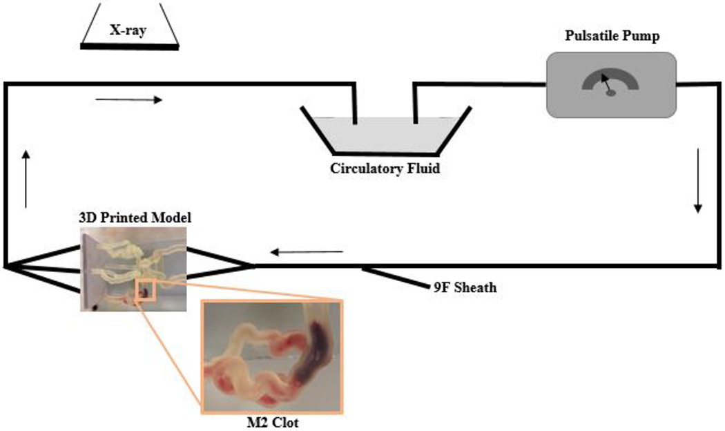
Phantoms were connected to a flow loop with a simulated physiologically relevant input flow rate and fluid temperature (Figure 2). Temperature is in particular a key factor since all current clot retrieval devices use Nitinol which has mechanical properties strongly dependent on the surrounding temperature. Standard digitally subtracted angiograms were taken prior to insertion of the clot and medical devices.
Figure 2:

Schematic representation of the clot model. The model contains separate inflow and outflow channels and is connected to a pulsatile pump via a closed circuit. Arrows indicate direction of flow. A 9 F sheath allows the introduction of guide catheters and thrombectomy devices. Biplane angiography is used during thrombectomy experiments. A zoomed in image of the 3D printed model displays a clot located within the M2.
Fresh clots were prepared by mixing 4 mL of fresh swine blood (no anticoagulant), 32 mg of fibrinogen from bovine plasma (Sigma-Aldrich, St Louis, Missouri, USA; catalog no.F8630), and 1 unit of thrombin from bovine plasma (Sigma-Aldrich, catalog no. T4648) in a 5 mL syringe for at least 3 min. The mixture was placed into plastic tubing (4 mm diameter) and incubated at room temperature for at least 60 min. Clots were then measured and cut using a scalpel into pieces of varying lengths for the experimentation.
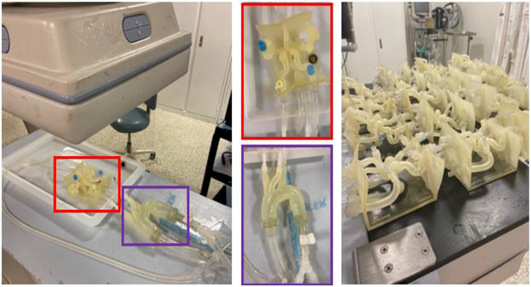
A clot was introduced into the model and placed anywhere in the M1 or M2 and clot location, composition (hard or soft clot), length, and angulation are recorded. The 3D printed patient specific models connected to a flow loop is shown in Figure 3. A stent retriever thrombectomy was then simulated in which the device is recorded, the outcome of the thrombectomy, and clot length. Overall, the following parameters were being studied within our experimentation: effect of angulation (angle of the vasculature in which the clot is placed), effect of collaterals (presence of anterior communicating artery and/or posterior communicating artery in the Circle of Willis), effect of atherosclerosis (severity of calcium build up), effect of clot morphology (hard/soft clots), and comparison of treatment approach (standard thrombectomy versus “push and fluff’ versus aspiration and stent retriever). Fluoroscopic images were taken after the thrombectomy to determine the treatment outcome. The treatment outcomes were ranked on the TICI scale as displayed in the angiograms in Figure 4.
Figure 3:

The 3D printed patient specific Circle of Willis is connected to a flow loop. (Red) The patient specific neurovasculature and (Purple) a standard aortic arch are highlighted. 20 different patient specific models have been printed. A clot is introduced into the proximal MCA and tests the effectiveness of stent retriever thrombectomy with TICI scoring system in patients with absent or robust collaterals of the circle of Willis using a conventional vs. BGC.
Figure 4:

The thrombolysis in cerebral infarction (TICI) scale ranks the rate of perfusion. TICI 0 = no perfusion, TICI 1 = penetration with minimal perfusion, TICI 2A = partial perfusion (less than 2/3) of the entire vascular territory visualized, TICI 2B = complete filling of all of the expected vascular territory visualized but the filling is at a decreased rate of time, TICI 3 = complete perfusion.
Statistical Analysis:
The following parameters were analyzed: clot angulation with the vasculature, initial clot length, clot composition, clot location within device, and clot location within vasculature. The clot angulation and the initial clot length were both analyzed using a single ANOVA test. A p-value <0.005 was considered indicative of a statistically significant correlation. F > Fcrit determines that we rejected the null hypothesis and was considered a statistically significant correlation. The clot composition, clot location within device and clot location within vasculature data was analyzed as a Poisson regression and the cumulative incidences of unsuccessful cases were used to determine the incidence rate ratios.
3. Results
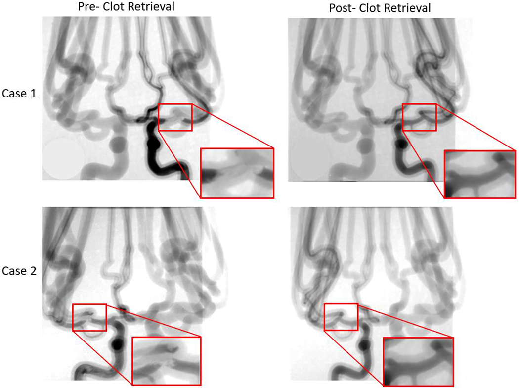
Using these phantoms, angiograms were captured before recanalization, showing the extent of the thrombus, after the stent retriever is deployed, and after the thrombectomy has taken place to determine the recanalization outcome using the TICI scoring system. Figure 5 displays the change in blood flow before and after the stent retriever has been deployed. Table 1 shows typical parameters recorded, 10 of the 42 experiments before/during/after stent retriever thrombectomy within our benchtop models to display the parameters we collected during the experimentation.
Figure 5:

Angiograms were taken both pre- and post- stent retriever thrombectomy was completed. Pre- clot retrieval, there is very little or no contrast flowing at the location of the clot. Post- clot retrieval there is contrast flowing through the part of the vessel where the clot was removed. Case 1 and case 2 in this figure display this significant change in fluidic flow at the location of the clot. The red boxes are enlarged views of the specific locations where the contract flow changes.
Table 1:
We collected the following data points for all 42 of our cases to analysis changes before and after recanalization.
| Case | Location | Clot Composition (Soft/Hard) | Clot Length Before (mm) | Clot Length After (mm) | Clot Location Within Device | MCA Angulation (degrees) | Outcome | Simplified Outcome |
|---|---|---|---|---|---|---|---|---|
| 1 | Prox M2 | S | 12 | 12 | Prox | 90 | Clot retrieved, TICI 3 | Retrieved |
| 2 | Prox M1 | H | 9 | 6 | Mid | 180 | Clot not grabbed | Not grabbed |
| 3 | Prox M2 | H | 11 | 10 | Mid | 110 | Clot lost in Pcom | Lost |
| 4 | Distal M2 | S | 25 | 3 | Prox | 90 | Clot partially retrieved, TICI 2, remnants in ACA | Partially retrieved |
| 5 | Prox M2 | S | 12 | 12 | Prox | 120 | Clot retrieved, TICI 3 | Retrieved |
| 6 | M2 | S | 25 | 25 | Mid | 180 | Clot not grabbed | Lost |
| 7 | M2 | S | 25 | 25 | Prox | 60 | Clot retrieved, TICI 3, removed with BGC and aspiration | Retrieved |
| 8 | Prox M1 | H | 9 | 6 | Mid | 180 | Clot not grabbed | Not grabbed |
| 9 | M2 | S | 25 | 25 | Distal | 180 | Clot lost in M2 | Retrieved |
| 10 | ICA bifurcation | S | 12 | 12 | Mid | 90 | Clot retrieved, TICI 2a | Retrieved |
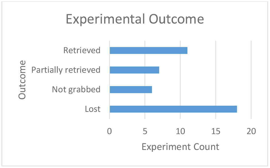
The experimental outcome was recorded for each experiment as retrieved, partially retrieved, not grabbed, and lost (Figure 6). We defined a successful outcome as ‘partially retrieved’ or ‘retrieved’ and an unsuccessful outcome as ‘lost’ or ‘not grabbed’. Based on our results, 18 of the 42 benchtop experiments were successful. The results for the 42 experiments have been analyzed based on the parameters we changed within the study to determine their significance to experimental outcome. The following parameters were analyzed: clot angulation with the vasculature (Table 2), initial clot length (Table 3), clot composition (Table 4), clot location within device (Table 5), and clot location within vasculature (Table 6).
Figure 6:

An experimental outcome was determined for each of the 42 benchtop experiments performed as ‘retrieved,’ ‘partially retrieved,’ ‘not grabbed,’ or ‘lost.’
Table 2:
Effect of Clot Angulation within Vasculature on Experimental Outcome. A single factor ANOVA test was completed to determine whether a change of clot angulation has an effect on the experimental outcome.
| Groups | Average (degrees) | Variance (degrees) | F | P-value | Fcrit | Conclusion |
|---|---|---|---|---|---|---|
| Unsuccessful | 148.125 | 1666.984 | 11.0270 | 0.102 | 4.084 | Insignificant |
| Successful | 103.611 | 2093.546 |
Table 3:
Effect of Initial Clot Length on Experimental Outcome. A single factor ANOVA test was completed to determine whether a change in the initial clot length has an effect on the experimental outcome.
| Groups | Average (mm) | Variance (mm) | F | P-value | Fcrit | Conclusion |
|---|---|---|---|---|---|---|
| Unsuccessful | 14.7916 | 48.606 | 2.789 | 0.102 | 4.084 | Insignificant |
| Successful | 18.3888 | 46.486 |
Table 4:
Effect of Clot Composition on Experimental Outcome. Cumulative incidence values and a rate ratio were calculated to determine whether a change in the clot composition has an effect on the experimental outcome.
| Groups | Unsuccessful | Successful | Total | Cumulative Incidence |
|---|---|---|---|---|
| Hard Clot | 9 | 0 | 9 | 9/9 = 100% |
| Soft Clot | 14 | 18 | 32 | 14/32 = 43.75% |
Rate Ratio = 100/43.75 = 2.29
Table 5:
Effect of Clot Location within Device on Experimental Outcome. Cumulative incidence values and rate ratios were calculated to determine whether a change in the clot location within the device has an effect on the experimental outcome.
| Groups | Unsuccessful | Successful | Total | Cumulative Incidence |
|---|---|---|---|---|
| Mid | 16 | 8 | 24 | 16/24 = 66.66% |
| Proximal | 6 | 9 | 15 | 2/4 = 50% |
| Distal | 1 | 1 | 2 | 1/2 = 50% |
Rate Ratio (Mid/Proximal) = 66.66/50 = 1.33
Rate Ratio (Mid/Distal) = 66.66/50 = 1.33
Rate Ratio (Proximal/Distal) = 50/50 = 1.00
Table 6:
Effect of Clot Location within Vasculature on Experimental Outcome. Cumulative incidence values were calculated to determine whether a change in the clot location within the vasculature has an effect on the experimental outcome.
| Groups | Unsuccessful | Successful | Total | Cumulative Incidence |
|---|---|---|---|---|
| Mid M1 | 4 | 1 | 5 | 4/5 = 80% |
| Proximal M1 | 3 | 3 | 6 | 3/6 = 50% |
| Distal M1 | 1 | 1 | 2 | 1/2 = 50% |
| Proximal M2 | 6 | 2 | 8 | 6/8 = 75% |
| Mid M2 | 6 | 8 | 14 | 6/14 = 42.86% |
| Distal M2 | 0 | 1 | 1 | 0/1 = 0% |
| M1/M2 Bifurcation | 4 | 2 | 6 | 4/6 = 66.66% |
4. Discussion
This project employs a novel approach that combines 3D model manufacturing technology with the ability to generate patient-specific anatomical variants for accurate simulation of real-world clinical scenarios of AIS from LVO treated with mechanical thrombectomy. Through the evaluation of controlled changing parameters within our experimental setup, we were able to determine single variable significance on the experimental outcome of a thrombectomy procedure using 3D printed patient specific phantoms.
Based on the results we obtained when looking at a change in clot angulation within the vasculature using a single factor ANOVA test, the experimental outcome is indeed significantly affected. A p-value of 0.0019 was reported as well as F > Fcrit (11.02 > 4.08) therefore rejecting the null hypothesis that the mean of unsuccessful and successful are equivalent. Upon analyzing the change in initial clot length, the experimental outcome is insignificantly affected. A p-value of 0.1027 was reported as well as F<Fcrit (2.79 < 4.08) therefore the null hypothesis was accepted. To analyze the effect of clot composition on the experimental outcome, cumulative incidence percentages and a rate ratio were calculated. It can be concluded from the statistical analysis that phantoms that underwent thrombectomy using a hard clot had 2.29 times the risk of unsuccessful treatment compared to using a soft clot for the experimentation. When looking at the results for the effect of the clot location within the device on the experimental outcome, we also calculated cumulative incidence percentages and rate ratios. It can be concluded from the rate ratio results that phantoms that underwent thrombectomy with the clot located mid-way through the device has 1.33 times the risk of unsuccessful treatment compared to both proximal and distal positioning. Proximal and distal clot locations within the device are equivalently comparable in regards to risk of unsuccessful treatment. Lastly, the clot location within the vasculature as an effect on the experimental outcome was investigated and analyzed with cumulative incidence values. Of note, 80% of clots placed Mid M1, 75% of clots placed Prox M2, and 66.66% of clots placed at the M1/M2 bifurcation were shown to be unsuccessful with the remaining clot locations within the vasculature having cumulative incidence percentages below 50%.
5. Conclusions
The main advantage of using this in vitro model of thrombectomy is that it provides a highly controlled environment where only a single variable (such as angulation of MCA or atherosclerosis) or treatment approach can be changed at a time. This project is allowing us to gain knowledge of how such characteristics influence thrombectomy success can be used in making clinical decisions when planning the procedure and selecting specific thrombectomy tools and approaches.
6. Acknowledgments
This work has been supported by NIH grant 1R01EB030092 and R21 NS109575-01.
References
- [1].Campbell BC, Hill MD, Rubiera M et al. , “Safety and efficacy of solitaire stent thrombectomy: individual patient data meta-analysis of randomized trials,” Stroke, 47(3), 798–806 (2016). [DOI] [PMC free article] [PubMed] [Google Scholar]
- [2].Turk III AS, Siddiqui A, Fifi JT et al. , “Aspiration thrombectomy versus stent retriever thrombectomy as first-line approach for large vessel occlusion (COMPASS): a multicentre, randomised, open label, blinded outcome, non-inferiority trial,” The Lancet, 393(10175), 998–1008 (2019). [DOI] [PubMed] [Google Scholar]
- [3].Jauch EC, Saver JL, Adams HP Jr et al. , “Guidelines for the early management of patients with acute ischemic stroke: a guideline for healthcare professionals from the American Heart Association/American Stroke Association,” Stroke, 44(3), 870–947 (2013). [DOI] [PubMed] [Google Scholar]
- [4].Goyal M, Menon BK, van Zwam WH et al. , “Endovascular thrombectomy after large-vessel ischaemic stroke: a meta-analysis of individual patient data from five randomised trials,” The Lancet, 387(10029), 1723–1731 (2016). [DOI] [PubMed] [Google Scholar]
- [5].Mokin M, Setlur Nagesh SV, Ionita CN et al. , “Stent retriever thrombectomy with the Cover accessory device versus proximal protection with a balloon guide catheter: in vitro stroke model comparison,” J Neurointerv Surg, 8(4), 413–7 (2016). [DOI] [PubMed] [Google Scholar]
- [6].Mokin M, Setlur Nagesh SV, Ionita CN et al. , “Comparison of modern stroke thrombectomy approaches using an in vitro cerebrovascular occlusion model,” AJNR Am J Neuroradiol, 36(3), 547–51 (2015). [DOI] [PMC free article] [PubMed] [Google Scholar]
- [7].Mokin M, Ionita CN, Nagesh SV et al. , “Primary stentriever versus combined stentriever plus aspiration thrombectomy approaches: in vitro stroke model comparison,” J Neurointerv Surg, 7(6), 453–7 (2015). [DOI] [PMC free article] [PubMed] [Google Scholar]
- [8].Sommer K, Izzo RL, Shepard L et al. , “Design Optimization for Accurate Flow Simulations in 3D Printed Vascular Phantoms Derived from Computed Tomography Angiography,” Proc SPIE Int Soc Opt Eng 10138, (2017). [DOI] [PMC free article] [PubMed] [Google Scholar]
- [9].Sommer KN, Shepard L, Karkhanis NV et al. , “3D Printed Cardiovascular Patient Specific Phantoms Used for Clinical Validation of a CT-derived FFR Diagnostic Software,” Proc SPIE Int Soc Opt Eng, 10578, (2018). [DOI] [PMC free article] [PubMed] [Google Scholar]
- [10].Shepard LM, Sommer KN, Angel E et al. , “Initial evaluation of three-dimensionally printed patient-specific coronary phantoms for CT-FFR software validation,” J Med Imaging (Bellingham), 6(2), 021603 (2019). [DOI] [PMC free article] [PubMed] [Google Scholar]
- [11].Sommer KN, Iyer V, Kumamaru KK et al. , “Method to simulate distal flow resistance in coronary arteries in 3D printed patient specific coronary models,” 3D Print Med, 6(1), 19 (2020). [DOI] [PMC free article] [PubMed] [Google Scholar]
- [12].Russ M, O’Hara R, Setlur Nagesh SV et al. , “Treatment Planning for Image-Guided Neuro-Vascular Interventions Using Patient-Specific 3D Printed Phantoms,” Proc SPIE Int Soc Opt Eng, 9417, (2015). [DOI] [PMC free article] [PubMed] [Google Scholar]
- [13].Meess KM, Izzo RL, Dryjski ML et al. , “3D Printed Abdominal Aortic Aneurysm Phantom for Image Guided Surgical Planning with a Patient Specific Fenestrated Endovascular Graft System,” Proc SPIE Int Soc Opt Eng, 10138, (2017). [DOI] [PMC free article] [PubMed] [Google Scholar]
- [14].Izzo RL, O’Hara RP, Iyer V et al. , “3D Printed Cardiac Phantom for Procedural Planning of a Transcatheter Native Mitral Valve Replacement,” Proc SPIE Int Soc Opt Eng, 9789, (2016). [DOI] [PMC free article] [PubMed] [Google Scholar]
- [15].Sommer KN, Shepard LM, Mitsouras D et al. , “Patient-specific 3D-printed coronary models based on coronary computed tomography angiography volumes to investigate flow conditions in coronary artery disease,” Biomedical Physics & Engineering Express, (2020). [DOI] [PubMed] [Google Scholar]
- [16].Tabaczynski J, [Mechanical Assessment of 3D Printed Patient Specific Phantoms for Simulation of Minimally Invasive Image Guided Procedures] State University of New York at Buffalo, (2018). [Google Scholar]
- [17].Ionita CN, Mokin M, Varble N et al. , “Challenges and limitations of patient-specific vascular phantom fabrication using 3D Polyjet printing.” 9038, 90380M. [DOI] [PMC free article] [PubMed] [Google Scholar]
- [18].Mokin M, Waqas M, Nagesh SVS et al. , “Assessment of distal access catheter performance during neuroendovascular procedures: measuring force in three-dimensional patient specific phantoms,” Journal of neurointerventional surgery, 11(6), 619–622 (2019). [DOI] [PubMed] [Google Scholar]
- [19].Shepard LM, Sommer KN, Angel E et al. , “Initial evaluation of three-dimensionally printed patient-specific coronary phantoms for CT-FFR software validation,” Journal of Medical Imaging, 6(2), 021603 (2019). [DOI] [PMC free article] [PubMed] [Google Scholar]
- [20].Sherman J, Rangwala HS, Ionita CN et al. , “Investigation of new flow modifying endovascular image-guided interventional (EIGI) techniques in patient-specific aneurysm phantoms (PSAPs) using optical imaging.” 6918, 69181V. [DOI] [PMC free article] [PubMed] [Google Scholar]
- [21].Steinman DA, Hoi Y, Fahy P et al. , “Variability of computational fluid dynamics solutions for pressure and flow in a giant aneurysm: the ASME 2012 Summer Bioengineering Conference CFD Challenge,” Journal of biomechanical engineering, 135(2), 021016 (2013). [DOI] [PubMed] [Google Scholar]


