Abstract
Micro- and nanoscale patterned monolayers of plasmonic nanoparticles were fabricated by combining concepts from colloidal chemistry, self-assembly, and subtractive soft lithography. Leveraging chemical interactions between the capping ligands of pre-synthesized gold colloids and a polydimethylsiloxane stamp, we demonstrated patterning gold nanoparticles over centimeter-scale areas with a variety of micro- and nanoscale geometries, including islands, lines, and chiral structures (e.g., square spirals). By successfully achieving nanoscale manipulation over a wide range of substrates and patterns, we establish a powerful and straightforward strategy, nanoparticle chemical lift-off lithography (NP-CLL), for the economical and scalable fabrication of functional plasmonic materials with colloidal nanoparticles as building blocks, offering a transformative solution for designing next-generation plasmonic technologies.
Graphical Abstract
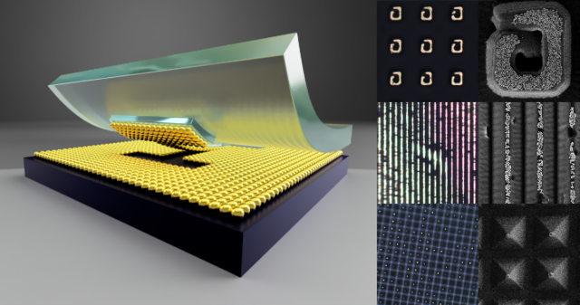
Plasmon resonances confine light in sub-diffraction volumes, enhancing light-matter interactions and driving a variety of nanoscale phenomena, including amplification of linear1,2 and non-linear3,4 optical processes, photothermal conversion,5,6 hot-carrier generation,7 and strong-coupling interactions.8,9 These capabilities place plasmonics at the intersection of nanophotonics and nanoelectronics, offering solutions for ultra-small light sources, quantum-computing, and opto-electronic devices.10 Colloidal noble metal nanoparticles are one of the most versatile platforms for engineering plasmonic resonances given the remarkable control over their crystallographic structure and optical properties offered by wet-chemistry synthesis.11,12 Manipulation of their size, shape, composition, and surface chemistry is applied to tailor the resonant frequencies,13 polarity,14 chirality,15 and spatial localization16 of the plasmons. When plasmonic nanostructures are organized in periodic patterns (i.e., in one, two, or three dimensions), they generate lattice plasmon resonances17 delocalized over hundreds of microns, which are characterized by narrower absorption linewidths.18,19 The wavelength of the generated lattice resonance is a function of the particle composition, the lattice parameter, and the refractive index of the substrates. For this reason, such architectures have been used to improve the detection limits of plasmonic sensing as well as to support high harmonic generation and lasing.20,21 However, these types of substrates are usually fabricated using conventional lithographic processes together with thermal- or electro-deposition of metals, yielding polycrystalline structures with higher intrinsic optical loss.22 Recently, the combination of soft lithography and self-assembly were explored for fabricating large-area micro- and nanoscale hierarchical structures and periodic arrays from colloidal nanoparticles.23–26 However, a generalized approach that could adapt to different plasmonic building-block sizes, shapes and compositions, and different substrate materials has not yet been realized.27 Moreover, accessing nanoscale features with high fidelity over large areas remains a challenge.28–30 Chemical lift-off lithography (CLL) is a subtractive patterning technique originally introduced for generating metal patterns via self-assembly monolayer patterning and etching and recently extended to a wider array of materials.31–34 Unlike additive microcontact printing, CLL uses chemical interactions between the ink and the stamp to push the resolution limit down to tens of nanometers or lower.31,32,35 Here, we present a versatile approach, nanoparticle chemical lift-off lithography (NP-CLL), which combines colloidal nanochemistry and lithographic patterning. This technique takes advantage of condensation chemistry for organizing pre-synthetized plasmonic nanoparticles into arbitrary micro- and nanoscale patterns, including islands, lines, and square spirals.
The advance at the core of our approach lies in the application of pre-synthetized mercaptoalkanol-capped gold nanoparticles (AuNPs), which are organized into monolayers and later undergo a condensation reaction with a patterned elastomeric stamp.
The AuNPs are first self-assembled into monolayers at a liquid-liquid interface, exploiting fine control over three effects:36,37 i) spontaneous migration of nanoparticles towards the interface to reduce the surface tension between two immiscible liquids; ii) colloidal instability triggered by high ionic strength resulting from the addition of tetrabutylammonium tetraphenylborate (TBA-TPB); and iii) nanoparticle resistance towards aggregation conferred by the thiol ligand. Gold nanoparticle monolayers are then transferred to desired substrates using a custom-built automated dip coater (Figure 1A and Figure S1, Supporting Information). This self-assembly approach has the benefit of being extremely versatile and straightforward to adapt for particles with different sizes, shapes, and compositions.36 Moreover, it is easily scalable to tens of centimeters, enabling the use of the described patterning technique for the preparation of wafer-scale devices. As for the thiol ligand, we used (11-mercaptoundecyl)hexa(ethylene glycol) (MUHEG), which is capable of stabilizing colloids up to 100 nm in aqueous media (See Figure S2 for details and characterization of the synthesized colloids).
Figure 1:
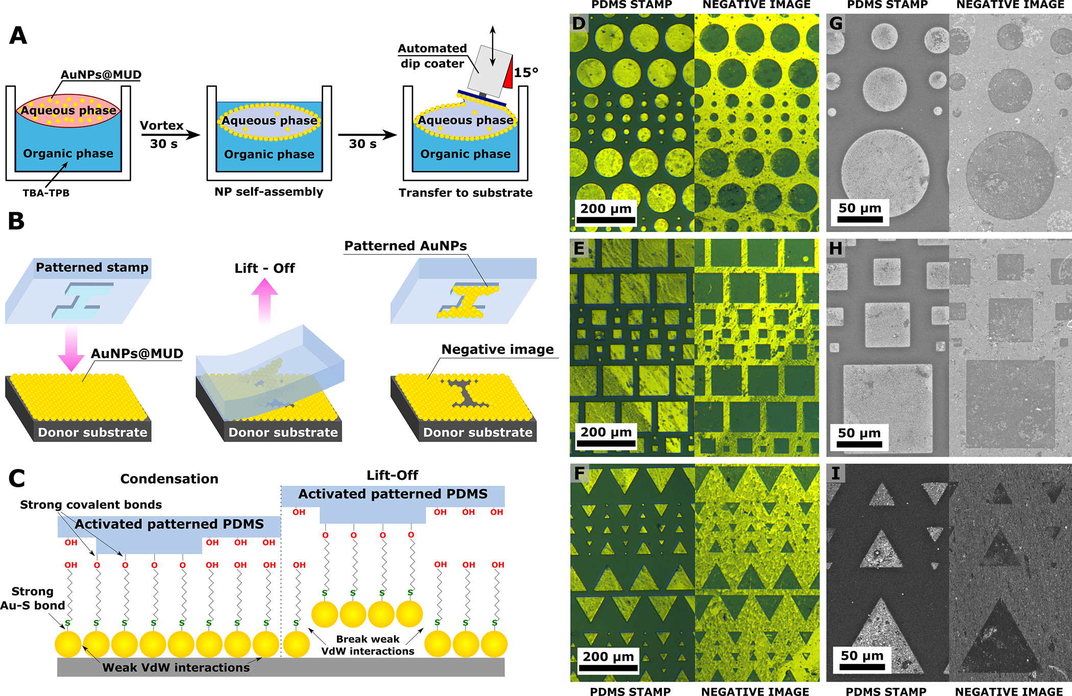
(A,B) Schematic of gold nanoparticle (AuNP) self-assembly at the liquid-liquid interface (A), and the chemical lift-off lithography (CLL) process on the assembled AuNP monolayer (B). (C) Schematic of the interactions that occur during CLL. (D-I) Optical images (D, E, F), and scanning electron microscopy (G, H, I) of a polydimethylsiloxane (PDMS) patterned stamp after lift-off (left) and the corresponding complementary negative image imprinted in the AuNP monolayer donor substrate (right). Additional images can be found in Figure S4.
The NP-CLL patterning process consists of conformally contacting an activated, patterned polydimethylsiloxane (PDMS) stamp directly onto the AuNP monolayer donor substrate (Figure 1B) at 60 °C for 3 h in an oven. During this time, the hydroxyl termini on both the activated PDMS and the mercaptoalkanol-coated AuNPs undergo condensation reactions yielding strong covalent bonds in the contact regions. Figure 1C illustrates the three main interactions in the system: i) the covalent ether bonds formed between the mercaptoalkanol ligand and the PDMS; ii) the sulfur-gold bonds between the thiols and the AuNP surface; and iii) the AuNP-AuNP and AuNP-substrate van der Waals (VdW) interactions. The interplay of these forces was exploited to generate patterned monolayers of AuNPs, i.e., when the PDMS stamp is removed, the weak VdW interactions are more readily broken. Therefore, the AuNPs in contact with the patterned regions of the stamp are “lifted-off” with the PDMS, leaving a complementary negative image of the pattern on the donor substrate (Figure 1B). Figure 1 shows optical and scanning electron microscopy (SEM) images of patterned substrates obtained by lifting-off 50 ± 3 nm MUHEG-capped AuNPs (Figure S2) using a stamp with 10–100 μm features (Figure S3). Continuous smooth curved lines and straight edges were both reproduced with high fidelity using NP-CLL (Figure S4). However, particle vacancies and clusters can be observed in the lifted-off regions. We believe that these imperfections are largely originated in the original gold nanoparticle monolayer. The application of a positive pressure before lift-off would help improve the uniformity of contact with the PDMS stamp but would induce deformation of the stamp itself. Another possible approach would be to accelerate the condensation reaction by performing the CLL process at higher temperature, although the range would be limited by gold colloid and PDMS stability. The described NP-CLL mechanism was validated further in a control experiment where the same procedure was repeated without activation of the patterned PDMS. In this case, no particles were observed to be transferred from the donor substrate to the stamp (Figure S5), consistent with the condensation reaction being the driving mechanism for lift-off.
During the preparation of the initial nanoparticle monolayers, an increment in the concentration of Au NPs in the aqueous phase during assembly of the liquid-liquid interface can result in nanoparticle multilayers. However, this result does not affect lift-off and still yields patterned monolayers on the PDMS stamp, because the AuNP-AuNP and AuNP-substrate interactions are governed by similar VdW interactions. Based on this observation, we noted the possibility for engineering interparticle and substrate-particle interactions to fabricate patterned stacks of plasmonic nanostructures via NP-CLL.38 This strategy will be the subject of future implementations of the technique.
One of the advantages of NP-CLL is the simultaneous production of two patterned plasmonic substrates: the PDMS stamp with the lifted-off nanoparticles and the complementary negative image remaining on the AuNP monolayer. To this end, we demonstrated both consecutive NP-CLL as well as nanoparticle transfer printing using the prepared PDMS substrates (Scheme 1). In the former case, the complementary negative image is reused for secondary NP-CLL using an activated flat PDMS stamp and repeating the same procedure (Figure 2). In the latter case, the patterned AuNP monolayer is released from the PDMS stamp and transferred onto a receiving surface (Figure 3). For this procedure, we exploited the thermoplastic behavior of dry hydroxypropyl cellulose (HPC) films.39 Additionally, HPC is water soluble and thus can be used as a sacrificial layer, potentially expanding the versatility of this approach for integrating plasmonic building blocks with a variety of different substrate materials such as graphene, transition metal dichalcogenides, and semiconducting materials.39 The procedure is straightforward. In brief, a thin layer (~50 nm) of HPC is spin coated on a clean glass slide and placed in contact with the patterned stamp. Transfer of the nanoparticle layer is achieved by raising the temperature to 80 °C for 3 min. From electron microscopy inspection of the receiving substrate, we confirmed that patterned features are maintained. Moreover, we did not observe signs of coalescence of neighboring nanoparticles. It is important to note that the transferred pattern presents more vacancies, indicating that the transfer is only semi-quantitative (Figure 3B–E). The yield of the transfer could be improved by exposing the patterned AuNP stamp to a UV-ozone treatment prior to the microcontact printing step. This treatment breaks the thiol-Au bonds that anchor the particles to the PDMS stamp,40 facilitating the transfer upon contact with the receiving substrate. However, this procedure can damage AuNPs if non-spherical structures are used, due to removal of the capping ligands and consequent reshaping that minimizes the surface energy of the nanocrystals.41
Scheme 1:
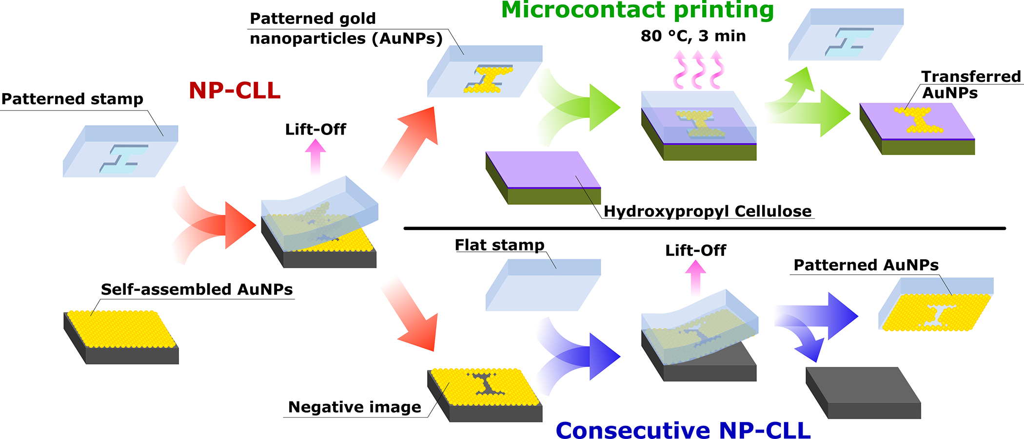
Overview of the three lithographic procedures: nanoparticle chemical lift-off lithography (NP-CLL, red), microcontact printing (green), and consecutive NP-CLL (blue). AuNPs: Au nanoparticles.
Figure 2: Consecutive nanoparticle chemical lift-off lithography (NP-CLL).
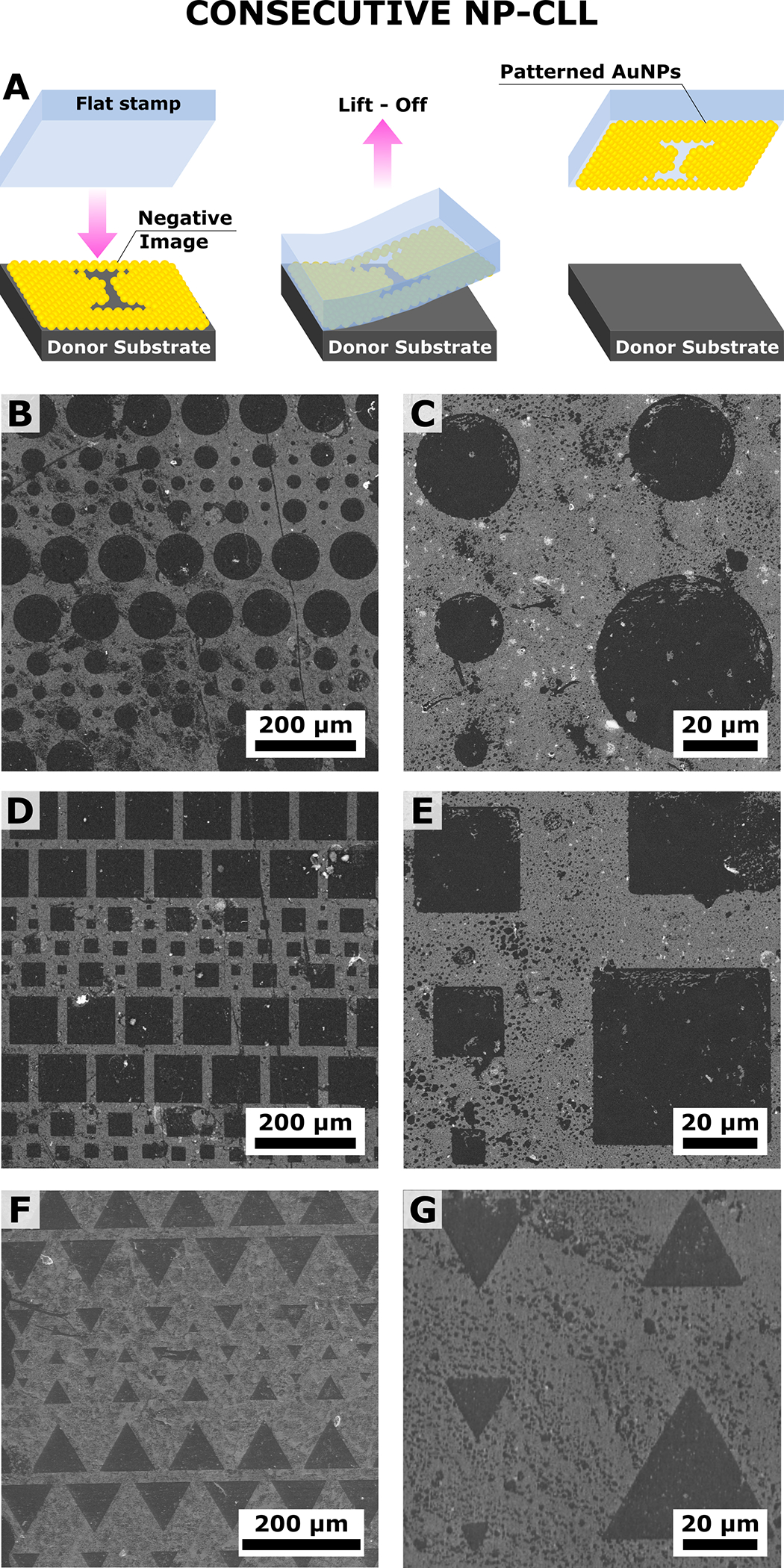
(A) Schematic illustration and (B-E) scanning electron microscopy images at different magnifications of the lift-off of a complementary negative image imprinted into the original gold nanoparticle (Au NPs) monolayer using a flat PDMS stamp. Additional images are provided in Figure S6.
Figure 3: Microcontact printing.
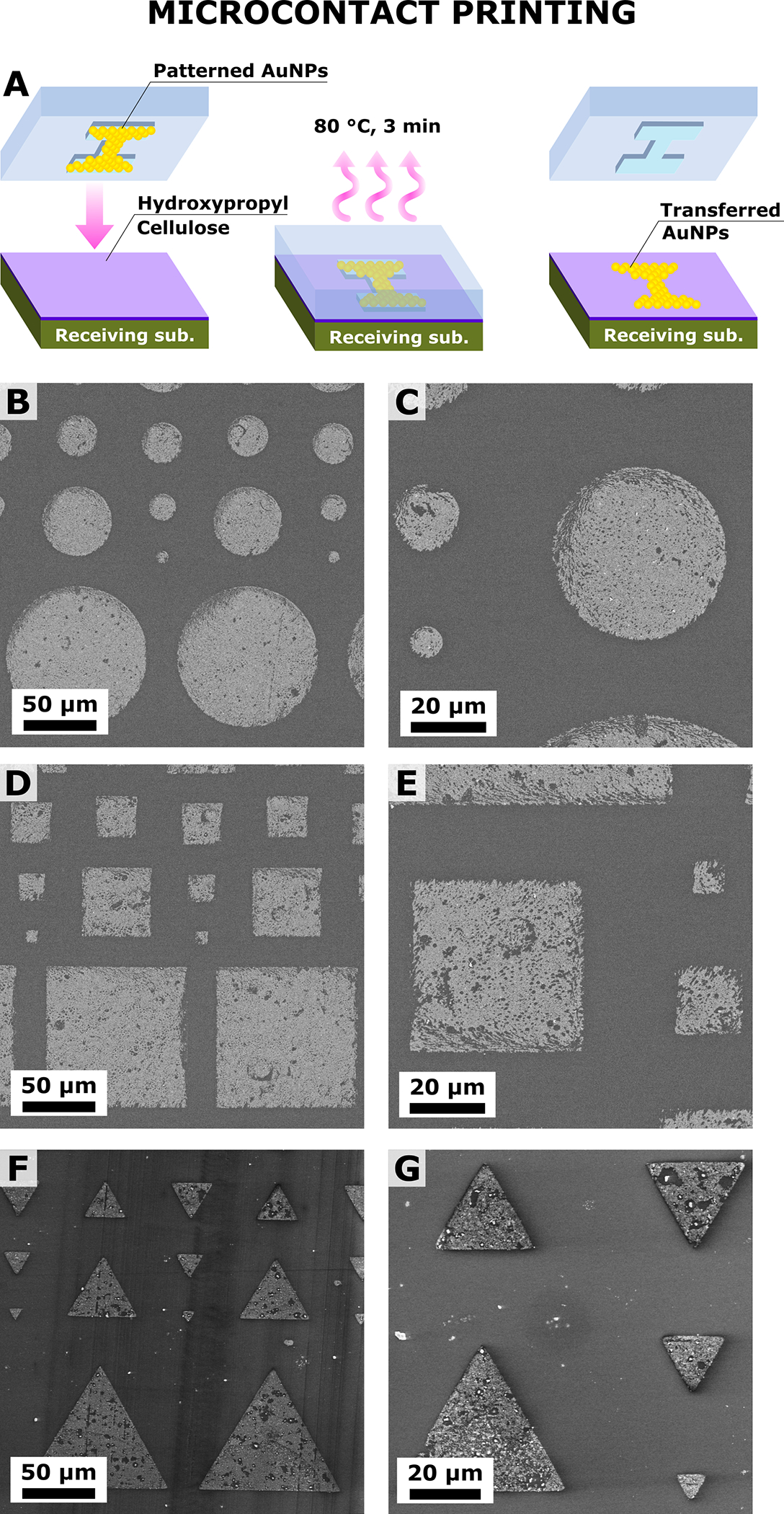
(A) Schematic illustration and (B-G) scanning electron microscopy at different magnifications of the patterns of gold nanoparticles (AuNPs) transferred from a patterned stamp to a clean glass substrate via contact printing mediated by hydroxypropyl cellulose. Additional images are shown in Figure S7.
We have achieved high-fidelity micron-sized patterns with feature dimensions 300 times larger than single particles. However, NP-CLL offers the opportunity to push the resolution further by including features similar in size even to single particles. To demonstrate this capability, we used PDMS stamps comprised of pyramidal features with contact areas of ~200 nm × ~200 nm (Figure 4 and Figure S3) and compared lift-off from monolayers of two different particle sizes (Figure S8): 50 ± 3 nm, and 100 ± 9 nm (Figure S2). Successful NP-CLL was confirmed by optical and electron microscopy (Figure 4). As expected, the combination of pyramidal stamps with particles >50 nm led to lower numbers of lifted-off objects per contact area. In particular, SEM analysis confirms that small clusters of AuNPs can be lifted-off onto the tips of each pyramid feature over 5 mm × 5 mm areas (Figure 4D–F), giving lift-off yields of 79%, calculated as “occupied” over ~300 pyramids. Interestingly, the use of larger particles results in a higher fidelity reproduction of the pattern compared to smaller ones. We hypothesize that the presence of defects in the original monolayer has little effect on the fidelity when fewer particles are lifted-off. Moreover, pressure applied onto the PDMS stamp could be used as another way to modulate the contact area, and thus the quantity of AuNPs per pyramid, through stamp deformation, as in our prior work.35
Figure 4:
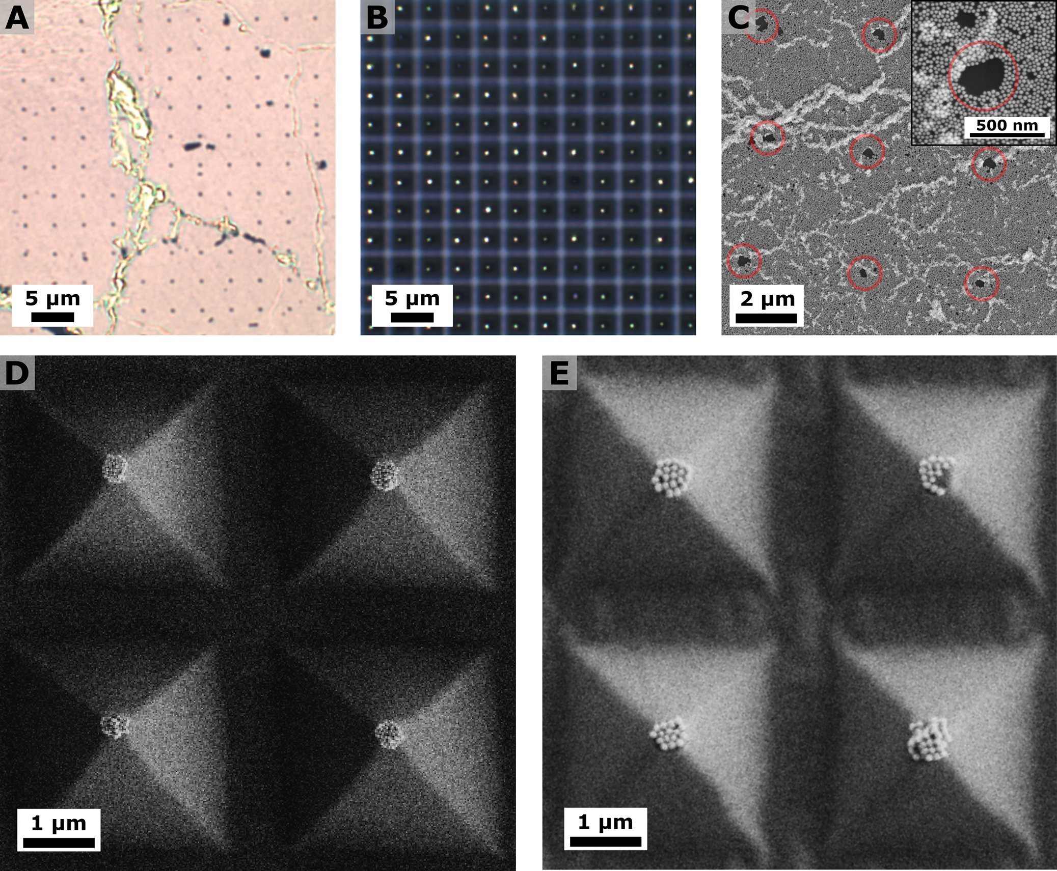
(A,B) Bright-field micrographs of the complementary negative image with the imprinted pyramid pattern into the nanoparticle monolayer (A) and the patterned polydimethylsiloxane (PDMS) after lift-off (B). (C) Scanning electron microscopy (SEM) analysis of the complementary negative image. Inset: higher magnification image of one circled area. (D-F) SEM of the patterned PDMS after lift-off using different nanoparticle dimensions: 50 ± 3 nm (D), and 100 ± 9 nm (E). SEM images of the patterned PDMS after lift-off applying low pressures are provided in Figure S9.
Overall, these results suggest the possibility for NP-CLL to reach single-particle manipulation. In fact, when attention was taken to apply only minimum pressure over the stamp, we occasionally observed the lift-off of either a few and/or single building blocks in small regions of the patterned PDMS (Figure S9). We note that applying weight evenly over large-scale stamps is challenging without specialized equipment.42 However, this limitation could be addressed using polymers with higher elastic moduli.43 Finally, we applied NP-CLL for the fabrication of AuNP patterns capable of long-range plasmon energy transfer. We prepared substrates with continuous lines of ~500 nm linewidth (Figure S3), corresponding to an average of 10 nanoparticles placed side-to-side. As reported by Fery and coworkers, these substrates are expected to sustain long-range plasmon propagation.44
Moreover, NP-CLL can be extended to patterns presenting corners and turns. This capability was demonstrated using square spiral patterns in both clockwise and counterclockwise orientations (Figure S3). Both the patterned PDMS and the complementary negative image imprinted on the nanoparticle monolayer were reproduced with high-fidelity and yield (Figure S10). The optical extinction of spiral structures was characterized in the entire visible-near-infrared (vis-NIR) range with randomized polarization. We measured a single broad plasmon band centered at ca. 800 nm (Figure 5A) that resembles the optical properties of the close-packed AuNP monolayer. The observed extinction spectrum suggests that the particle assembly is continuous along the dimensions of the spirals and thus eneables long-range plasmon propagation.45 Despite the intense scattering contribution from the micron-scale design of the pattern to the overall optical response, we attempt to characterize the chiral activity of the prepared patterns using a custom-built far-field circular dichroism setup in order to test the near-field plasmon propagation along the spirals. First, patterned nanoparticles were transferred on a glass slide using the HPC-mediated transfer strategy described in Figure 3. Scanning electron microscopy confirmed that the transfer maintained the structures intact and the AuNPs closely packed over the entire spiral structure (Figure 5B). Then, circular dichroism (CD) was measured in the vis-NIR region. The high fidelity of the spiral pattern enabled us to interrogate different regions of interest for each sample, as shown by optical images recorded from the CD setup (field of view ~ 0.07 mm2, Figure 5C). Extinction spectra of an L spiral sample, recorded with linearly, and left and right circularly polarized light are shown in Figure 5D. Differences between left and right circular polarization can be appreciated in the NIR region of the extinction spectra without need for further data processing. The CD was measured as the difference between the two extinction spectra, showing mirrored activity for the clockwise (L sample, in red) and the counterclockwise (R sample, in blue) square spirals (Figure 5E; see Instrumentation section in the Supporting Information for more details regarding data acquisition and processing).
Figure 5:
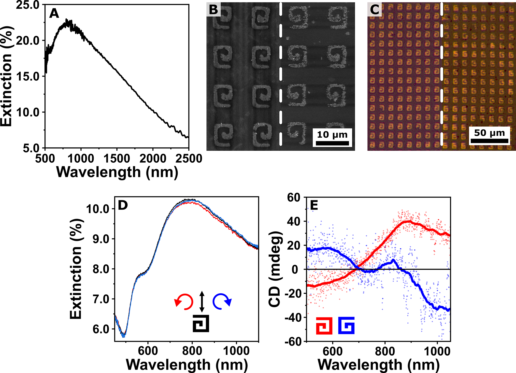
(A) Extinction spectra measured in the visible-near infrared (vis-NIR) range showing a single broad plasmonic band. (B,C) Scanning electron microscopy (B) and optical bright field (C) images of both clockwise (left) and counterclockwise (right) spirals, confirm that the close-packed particles form continuous structures. (D) Extinction spectra obtained illuminating a clockwise (L) sample with left circularly polarized light (red line), linearly polarized (black line), and right circularly polarized light (blue line). (E) Circular dichroism of a clockwise (L sample, red) and counterclockwise (R sample, blue) spiral structure. Savitky-Golay filtered signals (solid traces) are superimposed over the raw data (scattered dots). The inset drawings show the pattern orientation for the plotted spectra.
We interpret the relatively weak CD signal and small signal-to-noise ratio by the micrometer-scale dimensions of the prepared chiral patterns. Specifically, the broad excitation band formed by the sub-radiant propagating plasmon modes46 are dominated by the far-field scattering.45 We hypothesize that by reducing the dimensions of the spirals to submicron scales, and/or with the implementation of near-field techniques,47 the scattering could be decreased. As a result, the detectable optical activity could be significantly enhanced to target a broader range of applications. Overall, the reported data support the possibility of engineering chiral plasmonic assemblies using NP-CLL with colloidal nanoparticles, and we are currently pursuing studies in this direction.
In conclusion, we report the use of NP-CLL for the organization of plasmonic nanoparticles into micro- and nanoscale patterns as an alternative approach for the fabrication of functional photonic materials. The capability of NP-CLL to work with arbitrary patterns, including pyramids, lines, and square spirals was demonstrated, achieving, in the last case, chiral activity in the visible and near-infrared range. The potential to access nanoscale patterns using NP-CLL paves the way for targeting plasmonic arrays with lattice parameters compatible with sharp lattice plasmonic resonances in the vis-NIR region. Moreover, our results suggest the possibility of achieving single plasmonic object manipulation in two dimensions. Reaching this goal would enable preparation of plasmonic arrays similar to those prepared by standard lithographic methodologies but characterized by improved quality factors.19 Future pattern designs can be optimized to match the symmetry of the underlying AuNP assembly better in order to favor single particle lift-off. We anticipate that interparticle interactions can also be tuned via surface chemistry, adding another level of control over the lift-off process.48 Another possible advance with NP-CLL would be the implementation of anisotropic colloids. Although their self-assembly at the liquid-liquid interface has already been demonstrated,36 the use of anisotropic shapes would require a certain degree of control over their orientations in the original monolayer. Overall, NP-CLL could lead to the rational application of both in- and out-of-plane plasmonic modes, the exploitation of polarized resonances, and the introduction of chiral properties for the fabrication of meta-materials. Moreover, in combination with control over the surface chemistry of the plasmonic building blocks, our method opens opportunities for the construction of more complex, dynamic/reversible three-dimensional nanoscale architectures.49
Supplementary Material
ACKNOWLEDGMENTS
The authors would like to thank the Nanoquim clean room facility at ICMAB-CSIC, and in particular Dr. Luigi Morrone, for help with the use of the microwriter for master preparation. We acknowledge the CNSI-EICN, ICMAB-CSIC, and ICN2 electron microscopy facilities for TEM and SEM imaging, WiTEC for access to their microscopy instrumentation, and Dr. Thomas Young and Michael Mellody for the preparation of silicon masters. Special thanks to Dr. Leonora Velleman for the fruitful discussion on nanoparticle self-assembly. L.S. research is supported by the Marie Sklodowska-Curie Actions SHINE (H2020-MSCA-IF-2019, grant agreement No. 894847) and the 2020 Post-doctoral Junior Leader-Incoming Fellowship by “la Caixa” Foundation (ID 100010434, fellowship code LCF/BQ/PI20/11760028). L.A.P. thanks the Marie Sklodowska-Curie Actions (H2020-MSCA-IF-2018) for grant agreement No. 839402, PLASMIONICO. L.S., L.A.P., C.D., and A.M. acknowledge funding from the European Research Council (ERC) under the European Union’s Horizon 2020 research and innovation program (Grant Agreement No. 637116, ENLIGHTMENT). ICMAB acknowledges the Spanish Ministry of Economy and Competitiveness under grants PID2019-106860GB-I00 (AEI/FEDER, UE) and FUNFUTURE (CEX2019-000917-S) center of excellence Severo Ochoa program. This work has been performed in the framework of the doctorate in Materials Science of the Autonomous University of Barcelona. N.C. thanks support from the NIH NIBIB Pathway to Independence Award (K99EB028325). S.J.J. is supported by the NIH Common Fund through a NIH Director’s Early Independence Award co-funded by the National Institute of Dental and Craniofacial Research and Office of the Director, NIH Grant DP5OD028181. S.J.J. also acknowledges Young Investigator Award funds from the Alex’s Lemonade Stand Foundation for Childhood Cancer Research and the Hyundai Hope on Wheels Foundation for Pediatric Cancer Research. P.S.W. thanks the National Science Foundation (2004238) for support of this work. Funds for core facility use were provided via a support voucher awarded to NC and SJJ via the UCLA Clinical and Translational Science Institute (CTSI) Core Voucher Program, which is administered through Grant Number UL1TR001881.
Footnotes
The authors declare no competing financial interest.
ASSOCIATED CONTENT
Supporting Information. The Supporting Information is available free of charge on _________________. Materials, instrumentation, and experimental details for the synthesis of the different gold colloids, ligand exchange reaction, monolayer preparation and transfer, CLL, micro contact printing, and nanotransfer procedures. UV-visible, TEM and SEM characterization of gold colloids and prepared substrates.
REFERENCES
- (1).Bagheri S; Giessen H; Neubrech F Large-Area Antenna-Assisted SEIRA Substrates by Laser Interference Lithography. Adv. Opt. Mater. 2014, 2, 1050–1056. [Google Scholar]
- (2).Fort E; Grésillon S Surface Enhanced Fluorescence. J. Phys. D: Appl. Phys. 2007, 41, 013001. [Google Scholar]
- (3).Sherry LJ; Jin R; Mirkin CA; Schatz GC; Van Duyne RP Localized Surface Plasmon Resonance Spectroscopy of Single Silver Triangular Nanoprisms. Nano Lett. 2006, 6, 2060–2065. [DOI] [PubMed] [Google Scholar]
- (4).Zrimsek AB; Chiang N; Mattei M; Zaleski S; McAnally MO; Chapman CT; Henry A-I; Schatz GC; Van Duyne RP Single-Molecule Chemistry with Surface- and Tip-Enhanced Raman Spectroscopy. Chem. Rev. 2017, 117, 7583–7613. [DOI] [PubMed] [Google Scholar]
- (5).Bhattacharjee U; West CA; Hosseini Jebeli SA; Goldwyn HJ; Kong X-T; Hu Z; Beutler EK; Chang W-S; Willets KA; Link S; Masiello DJ Active Far-Field Control of the Thermal Near-Field via Plasmon Hybridization, ACS Nano 2019, 13, 9655–9663. [DOI] [PubMed] [Google Scholar]
- (6).Bi C; Chen J; Chen Y; Song Y; Li A; Li S; Mao Z; Gao C; Wang D; Möhwald H; Xia H Realizing a Record Photothermal Conversion Efficiency of Spiky Gold Nanoparticles in the Second Near-Infrared Window by Structure-Based Rational Design. Chem. Mater. 2018, 30, 2709–2718. [Google Scholar]
- (7).Cushing SK; Wu N Progress and Perspectives of Plasmon-Enhanced Solar Energy Conversion. J. Phys. Chem. Lett. 2016, 7, 666–675. [DOI] [PubMed] [Google Scholar]
- (8).Väkeväinen AI; Moerland RJ; Rekola HT; Eskelinen A-P; Martikainen J-P; Kim D-H; Törmä P Plasmonic Surface Lattice Resonances at the Strong Coupling Regime. Nano Lett. 2014, 14, 1721–1727. [DOI] [PubMed] [Google Scholar]
- (9).Ebbesen TW Hybrid Light–Matter States in a Molecular and Material Science Perspective. Acc. Chem. Res. 2016, 49, 2403–2412. [DOI] [PubMed] [Google Scholar]
- (10).Stockman MI; Kneipp K; Bozhevolnyi SI; Saha S; Dutta A; Ndukaife J; Kinsey N; Reddy H; Guler U; Shalaev VM; Boltasseva A; Gholipour B; Krishnamoorthy HNS; MacDonald KF; Soci C; Zheludev NI; Savinov V; Singh R; s PG; Lienau C; Vadai M; Solomon ML; Barton DR; Lawrence M; Dionne JA; Boriskina SV; Esteban R; Aizpurua J; Zhang X; Yang S; Wang D; Wang W; Odom TW; Accanto N; Roque P. M. de; Hancu IM; Piatkowski L; Hulst N. F. van; Kling MF Roadmap on Plasmonics. J. Opt. 2018, 20, 043001. [Google Scholar]
- (11).Scarabelli L Recent Advances in the Rational Synthesis and Self-Assembly of Anisotropic Plasmonic Nanoparticles. Pure Appl. Chem. 2018, 90, 1393–1407. [Google Scholar]
- (12).González-Rubio G; Oliveira T. M. de; Altantzis T; Porta AL; Guerrero-Martínez A; Bals S; Scarabelli L; M. Liz-Marzán L Disentangling the Effect of Seed Size and Crystal Habit on Gold Nanoparticle Seeded Growth. Chem. Commun. 2017, 53, 11360–11363. [DOI] [PubMed] [Google Scholar]
- (13).Mayer M; Scarabelli L; March K; Altantzis T; Tebbe M; Kociak M; Bals S; García de Abajo FJ; Fery A; Liz-Marzán LM Controlled Living Nanowire Growth: Precise Control over the Morphology and Optical Properties of AgAuAg Bimetallic Nanowires. Nano Lett. 2015, 15, 5427–5437. [DOI] [PMC free article] [PubMed] [Google Scholar]
- (14).Liu Q; Cui Y; Gardner D; Li X; He S; Smalyukh II Self-Alignment of Plasmonic Gold Nanorods in Reconfigurable Anisotropic Fluids for Tunable Bulk Metamaterial Applications. Nano Lett. 2010, 10, 1347–1353. [DOI] [PubMed] [Google Scholar]
- (15).Lee H-E; Ahn H-Y; Mun J; Lee YY; Kim M; Cho NH; Chang K; Kim WS; Rho J; Nam KT Amino-Acid- and Peptide-Directed Synthesis of Chiral Plasmonic Gold Nanoparticles. Nature 2018, 556, 360–365. [DOI] [PubMed] [Google Scholar]
- (16).Kociak M; Stéphan O Mapping Plasmons at the Nanometer Scale in an Electron Microscope. Chem. Soc. Rev. 2014, 43, 3865–3883. [DOI] [PubMed] [Google Scholar]
- (17).Kravets VG; Kabashin AV; Barnes WL; Grigorenko AN Plasmonic Surface Lattice Resonances: A Review of Properties and Applications. Chem. Rev. 2018, 118, 5912–5951. [DOI] [PMC free article] [PubMed] [Google Scholar]
- (18).Wang W; Watkins N; Yang A; Schaller RD; Schatz GC; Odom TW Ultrafast Dynamics of Lattice Plasmon Lasers. J. Phys. Chem. Lett. 2019, 10, 3301–3306. [DOI] [PubMed] [Google Scholar]
- (19).Li Z; Butun S; Aydin K Ultranarrow Band Absorbers Based on Surface Lattice Resonances in Nanostructured Metal Surfaces. ACS Nano 2014, 8, 8242–8248. [DOI] [PubMed] [Google Scholar]
- (20).Hooper DC; Kuppe C; Wang D; Wang W; Guan J; Odom TW; Valev VK Second Harmonic Spectroscopy of Surface Lattice Resonances. Nano Lett. 2019, 19, 165–172. [DOI] [PubMed] [Google Scholar]
- (21).Winkler JM; Ruckriegel MJ; Rojo H; Keitel RC; De Leo E; Rabouw FT; Norris DJ Dual-Wavelength Lasing in Quantum-Dot Plasmonic Lattice Lasers. ACS Nano 2020, 14, 5223–5232. [DOI] [PubMed] [Google Scholar]
- (22).Najmaei S; Mlayah A; Arbouet A; Girard C; Léotin J; Lou J Plasmonic Pumping of Excitonic Photoluminescence in Hybrid MoS2–Au Nanostructures. ACS Nano 2014, 8, 12682–12689. [DOI] [PubMed] [Google Scholar]
- (23).Hamon C; Novikov S; Scarabelli L; Basabe-Desmonts L; Liz-Marzán LM Hierarchical Self-Assembly of Gold Nanoparticles into Patterned Plasmonic Nanostructures. ACS Nano 2014, 8, 10694–10703. [DOI] [PubMed] [Google Scholar]
- (24).Tebbe M; Mayer M; Glatz BA; Hanske C; Probst PT; Müller MB; Karg M; Chanana M; König TAF; Kuttner C; Fery A Optically Anisotropic Substrates via Wrinkle-Assisted Convective Assembly of Gold Nanorods on Macroscopic Areas. Faraday Discuss 2015, 181, 243–260. [DOI] [PMC free article] [PubMed] [Google Scholar]
- (25).Matricardi C; Hanske C; Garcia-Pomar JL; Langer J; Mihi A; Liz-Marzán LM Gold Nanoparticle Plasmonic Superlattices as Surface-Enhanced Raman Spectroscopy Substrates. ACS Nano 2018, 12, 8531–8539. [DOI] [PubMed] [Google Scholar]
- (26).Chen C-Y; Chang C-H; Wang C-M; Li Y-J; Chu H-Y; Chan H-H; Huang Y-W; Liao W-S Large Area Nanoparticle Alignment by Chemical Lift-Off Lithography. Nanomaterials 2018, 8, 71. [DOI] [PMC free article] [PubMed] [Google Scholar]
- (27).Zhang H; Kinnear C; Mulvaney P Fabrication of Single-Nanocrystal Arrays. Adv. Mater. 2020, 32, 1904551. [DOI] [PubMed] [Google Scholar]
- (28).Santhanam V; Andres RP Microcontact Printing of Uniform Nanoparticle Arrays. Nano Lett. 2004, 4, 41–44. [Google Scholar]
- (29).Ginger DS; Zhang H; Mirkin CA The Evolution of Dip-Pen Nanolithography. Angew. Chem. Int. Ed. 2004, 43, 30–45. [DOI] [PubMed] [Google Scholar]
- (30).Wu Y; Jiang Y; Zheng X; Jia S; Zhu Z; Ren B; Ma H Facile Fabrication of Microfluidic Surface-Enhanced Raman Scattering Devices via Lift-up Lithography. R. Soc. Open Sci. 2018, 5, 172034. [DOI] [PMC free article] [PubMed] [Google Scholar]
- (31).Liao W-S; Cheunkar S; Cao HH; Bednar HR; Weiss PS; Andrews AM Subtractive Patterning via Chemical Lift-Off Lithography. Science 2012, 337, 1517–1521. [DOI] [PubMed] [Google Scholar]
- (32).Andrews AM; Liao W-S; Weiss PS Double-Sided Opportunities Using Chemical Lift-Off Lithography. Acc. Chem. Res. 2016, 49, 1449–1457. [DOI] [PubMed] [Google Scholar]
- (33).Cheung KM; Stemer DM; Zhao C; Young TD; Belling JN; Andrews AM; Weiss PS Chemical Lift-Off Lithography of Metal and Semiconductor Surfaces. ACS Mater. Lett. 2020, 2, 76–83. [DOI] [PMC free article] [PubMed] [Google Scholar]
- (34).Belling JN; Heidenreich LK; Park JH; Kawakami LM; Takahashi J; Frost IM; Gong Y; Young TD; Jackman JA; Jonas SJ; Cho N-J; Weiss PS Lipid-Bicelle-Coated Microfluidics for Intracellular Delivery with Reduced Fouling. ACS Appl. Mater. Interfaces 2020, 1p2, 45744–45752. [DOI] [PMC free article] [PubMed] [Google Scholar]
- (35).Xu X; Yang Q; Cheung KM; Zhao C; Wattanatorn N; Belling JN; Abendroth JM; Slaughter LS; Mirkin CA; Andrews AM; Weiss PS Polymer-Pen Chemical Lift-Off Lithography. Nano Lett. 2017, 17, 3302–3311. [DOI] [PubMed] [Google Scholar]
- (36).Velleman L; Scarabelli L; Sikdar D; Kornyshev AA; Liz-Marzán LM; Edel JB Monitoring Plasmon Coupling and SERS Enhancement Through in Situ Nanoparticle Spacing Modulation. Faraday Discuss. 2017, 205, 67–83. [DOI] [PubMed] [Google Scholar]
- (37).Velleman L; Sikdar D; A. Turek V; R. Kucernak A; J. Roser S; A. Kornyshev A; B. Edel J Tuneable 2D Self-Assembly of Plasmonic Nanoparticles at Liquid|liquid Interfaces. Nanoscale 2016, 8, 19229–19241. [DOI] [PubMed] [Google Scholar]
- (38).Nepal D; Onses MS; Park K; Jespersen M; Thode CJ; Nealey PF; Vaia RA Control over Position, Orientation, and Spacing of Arrays of Gold Nanorods Using Chemically Nanopatterned Surfaces and Tailored Particle–Particle–Surface Interactions. ACS Nano 2012, 6, 5693–5701. [DOI] [PubMed] [Google Scholar]
- (39).Dore C; Dörling B; Garcia-Pomar JL; Campoy-Quiles M; Mihi A Hydroxypropyl Cellulose Adhesives for Transfer Printing of Carbon Nanotubes and Metallic Nanostructures. Small 2020, 16, 2004795. [DOI] [PubMed] [Google Scholar]
- (40).Worley CG; Linton RW Removing Sulfur from Gold Using Ultraviolet/Ozone Cleaning. J. Vac. Sci. Technol. A 1995, 13, 2281–2284. [Google Scholar]
- (41).Hamon C; Novikov SM; Scarabelli L; Solís DM; Altantzis T; Bals S; Taboada JM; Obelleiro F; Liz-Marzan LM Collective Plasmonic Properties in Few-Layer Gold Nanorod Supercrystals. ACS Photonics 2015, 2, 1482–1488. [DOI] [PMC free article] [PubMed] [Google Scholar]
- (42).Huo F; Zheng Z; Zheng G; Giam LR; Zhang H; Mirkin CA Polymer Pen Lithography. Science 2008, 321, 1658–1660. [DOI] [PMC free article] [PubMed] [Google Scholar]
- (43).Odom TW; Love JC; Wolfe DB; Paul KE; Whitesides GM Improved Pattern Transfer in Soft Lithography Using Composite Stamps. Langmuir 2002, 18, 5314–5320. [Google Scholar]
- (44).Mayer M; Potapov PL; Pohl D; Steiner AM; Schultz J; Rellinghaus B; Lubk A; König TAF; Fery A Direct Observation of Plasmon Band Formation and Delocalization in Quasi-Infinite Nanoparticle Chains. Nano Lett. 2019, 19, 3854–3862. [DOI] [PMC free article] [PubMed] [Google Scholar]
- (45).Willingham B; Link S Energy Transport in Metal Nanoparticle Chains via Sub-Radiant Plasmon Modes. Opt. Express 2011, 19, 6450–6461. [DOI] [PubMed] [Google Scholar]
- (46).Zhao Y; Askarpour AN; Sun L; Shi J; Li X; Alù A Chirality Detection of Enantiomers Using Twisted Optical Metamaterials. Nat. Commun. 2017, 8, 14180. [DOI] [PMC free article] [PubMed] [Google Scholar]
- (47).Schattschneider P; Rubino S; Hébert C; Rusz J; Kuneš J; Novák P; Carlino E; Fabrizioli M; Panaccione G; Rossi G Detection of Magnetic Circular Dichroism Using a Transmission Electron Microscope. Nature 2006, 441, 486–488. [DOI] [PubMed] [Google Scholar]
- (48).Moaseri E; Bollinger JA; Changalvaie B; Johnson L; Schroer J; Johnston KP; Truskett TM Reversible Self-Assembly of Glutathione-Coated Gold Nanoparticle Clusters via PH-Tunable Interactions. Langmuir 2017, 33, 12244–12253. [DOI] [PubMed] [Google Scholar]
- (49).A. Grzybowski B; Fitzner K; Paczesny J; Granick S From Dynamic Self-Assembly to Networked Chemical Systems. Chem. Soc. Rev. 2017, 46, 5647–5678. [DOI] [PubMed] [Google Scholar]
Associated Data
This section collects any data citations, data availability statements, or supplementary materials included in this article.


