Abstract
A plane within reduced micromorphic model subjected to external static load is studied using the finite element method. The reduced micromorphic model is a generalized continuum theory which can be used to capture the interaction of the microstructure. In this approach, the microstructure is homogenized and replaced by a reduced micromorphic material model. Then, avoiding the complexity of the microstructure, the reduced micromorphic model is analyzed to reveal the interaction of the microstructure and the external loading. In this study, the three-dimensional formulation of the reduced micromorphic model is dimensionally reduced to address a plane under in-plane external load. The governing system of partial differential equations with corresponding consistent boundary conditions are discretized and solved using the finite element method. The classical and nonclassical deformation measures are then demonstrated and discussed for the first time for a material employing the reduced micromorphic model.
Subject terms: Mechanical engineering, Computational methods
Introduction
Materials with architectured microstructure provide efficient properties and have been in the focus of many research groups in the last few decades. Due to the feasibility of tailoring the microstructure to achieve auxetic behaviors, the analysis and design of such novel materials (referred also as metamaterials) are not possible within classical continuum mechanics. Accordingly, the generalized continua1–4 have regained the attention and have been employed for capturing the non-classical features of these materials such as size effect and band gap5. In addition to mechanical properties, such generalized theories have also been presented for multiphysics addressing e.g. electrical and magnetic properties6.
A thorough literature review on generalized continua is out of the scope and only a brief review is compiled here to introduce the subject. Nonlocal7,8,23, higher-order and higher-grade theories9–11 have been introduced as extensions of the classical continuum theories. Within higher order (or micro continuum theories), the classical three translational degrees of freedom (DOF) is augmented by additional DOFs stemming from the microstructure. These theories are two-level continuum models which consider the material as a collection of deformable point particles. Depending on the number of the additional DOFs, various theories such as micromorphic elasticity (with 12 DOFs), microstretch elasticity (with 7 DOFs), micropolar elasticity (with 6 DOFs)12, and dilatation elasticity (with 4 DOFs) are obtained.
An expected feature of the generalized continua is their numerous material constants which are to be determined for any specific microstructure via real or numerical experiments, e.g. see13. Although this task is commonly referred to as a “challenge” for the application of the generalized continua, one should not forget that capturing the nonclassical features are only possible due to the presence of such nonclassical material constants. Nevertheless, the generalization of the continuum theory should be performed with care to employ the most efficient model with the minimum number of material constants for the microstructure and the objective physical phenomenon to be captured. For this purpose, recently, computational homogenization has been successfully used for identifying and realizing a suitable continuum theory14–20,38. To this end, a comprehensive methodology capable of identifying the most efficient continuum theory for a specific heterogeneous material is not yet identified.
In addition to more classical versions of generalized continua, recent developments have been reported in the literature such as relaxed micromorphic model21 and reduced micromorphic model22. These models aim for filling the gaps in the realm of the generalized continua to provide an efficient selection of a generalized model without the need to include unnecessary extensions. In an attempt to reduce the number of material parameters and degrees of freedom, Neff et al.21 proposed a relaxed micromorphic model which uses the curl of the micro-deformation tensor as a micro-dislocation measure. Furthermore, the coupling between the micro-strain and the macro-strain is eliminated in this model. The relaxed micromorphic model has been used to model the wave propagation in metamaterials24–27.
Another form of the micromorphic model is proposed by Shaat22 which is referred to as the reduced micromorphic model (referred to, in this text, as RMM). In this model the author considers the coupling between the micro-strain and the macro-strain to measure the concept of so-called residual strain and consequently the residual stress. The model has been employed to investigate the wave propagation in metamaterials and composite materials. An application for the model is also introduced in28 to define the equivalent shear modulus of composite metamaterials. The reduced micromorphic model is also formulated in orthogonal curvilinear coordinates and an application to a metamaterial hemisphere has been reported using spherical coordinates29. Later, Shaat et al. introduced a micromorphic beam theory30 based on the reduced micromorphic model.
In the absence or due the complexity of an analytical solution31, the finite element method is an efficient numerical treatment of continuum theories. In this paper, the reduced micromorphic model is used together with the finite element method for the analysis of a plane. The framework is dimensionally reduced for planar analysis. Such dimension reduction is motivated as it can efficiently be used for the analysis of 2D structures32. The corresponding measures of deformation are elaborated to demonstrate the response of a plane within RMM subjected to static in-plane loading.
The paper is organized as follows. The reduced micromorphic model is reviewed in Section “The RMM in Cartesian coordinates”. In Section “The RMM model in 2-Dimension”, the proposed domain in two dimensions and the planar formulation are presented. After introducing the governing field equations and the variationally consistent boundary conditions, two case studies are defined. In Section “Numerical results”. the finite element analysis and numerical simulation of the two case studies are reported. Finally, the conclusion is given in Section “Conclusion”.
The RMM in Cartesian coordinates
The kinematical variables
The classical theories of continuum mechanics do not have the ability to represent the nanoscale phenomena. Accordingly, the generalized continua such as the reduced micromorphic model (RMM) is introduced as an alternative for studying such phenomena at the micro-scale level, where the model introduces the micro-strain tensor as an additional measure besides the displacement field. Moreover, it introduces the coupling between the strain tensor and the micro-strain tensor as a coupling measure with the elimination of the repeated effects.
In addition to its ability to reducing the material parameters, the RMM generates additional field equations and reduces the order of the partial differential equations of the model. Such reduction sometimes facilitates obtaining the analytical solutions.
The deformation occurring for elastic materials is an accumulative movement for the material points at the nanoscale. Moreover, the tools used in classical theories to measure the displacement ignore the internal movement of such points and is only limited to the movement of the surface points. Consequently, introducing new measures to describe the internal movement of the material points and eliminating the repeated effects resultant from two different actions, the kinematics of RMM is given by
| 1 |
where denote the classical strain tensor, is the micro-strain tensor, is the coupling between the micro-strain and the macro-strain and is the gradient of the micro-strain tensor .
Equations of motion
The variational method is a mathematical procedure that is used to obtain the field equations and the corresponding boundary conditions for the considered model. This procedure is used widely in continuum mechanics, fluid mechanics, optics, quantum mechanics, thermodynamics and electromagnetism. The total free energy function for the volume (volume of the body) bounded by the surface (surface of the body) is considered as a function with internal variables as
| 2 |
The first variation for the total free energy reads
| 3 |
The constitutive relations are defined as follows
| 4 |
where is the micro-stress tensor, is a Cauchy-like tensor or residual stress tensor, and is the higher order stress tensor, respectively.
Substituting Eq. (4) into Eq. (3) results in
| 5 |
Similar to the free energy, the kinetic energy is also generalized by considering the micro-inertia energy as
| 6 |
where is the macroscopic mass density of the metamaterial, is the mass density of the material particle, and denotes its micro-inertia. Additional terms can be considered in the kinetic energy to describe complex phenomena in the metamaterials as in33.
The first variation of kinetic energy is
| 7 |
Therefore, the total variation for internal energy reads
| 8 |
The work done by the external forces, , is defined as
| 9 |
where is the body force, is the body higher-order moment, is the Cauchy stress vector, is the higher stress tensor or double force, and is the wedge forces at the corners of the domain34. Here, are the vertex points. The variation of external work reads
| 10 |
Considering Eqs. (8) and (10), the Hamilton’s principle results in
| 11 |
Applying the divergence theorem, we get
| 12 |
Equation (12) is satisfied for all volumes bounded by smooth and unsmooth boundaries if and only if the integrands are zero. Consequently, equations of motion and corresponding boundary conditions for smooth boundaries enclosed a bounded volume are
| 13 |
and
| 14 |
Internal energy
According to22,28–30, the free energy in RMM is taken in the form
| 15 |
where and are the elastic moduli of the microstructure, and are the elastic moduli of the matrix material between two particles, and are two elastic moduli accounting for the coupling between the micro-strain and the macro-strain, and and are length scale parameters. The free energy function in two dimensions can be written in a matrix form as35
| 16 |
Therefore, the function is positive definite if the following conditions are satisfied
The constitutive relations
The constitutive relations are related to the free energy function by
| 17 |
Substituting the Eq. (15) into Eq. (17) and considering the deformation measures (1), the stress measures can be expressed in terms of deformation measures as
| 18 |
General field equations
Considering the Eqs. (13) and (18) and using the condition , the general field equations read
| 19 |
| 20 |
Equations (19), (20) represent the governing field equations for the RMM model, which should be satisfied inside the domain of the solution. In the limiting case, by neglecting the micro-strain tensors and the second equation, the RRM model is reduced to the classical model of elasticity.
The RMM model in 2-Dimension
The field equations in 2D
We consider a rectangular () plane which behaves according to the RMM model. In order to study the interaction between the applied forces and the induced internal fields in the material, we consider planar displacement field and micro-strain field as follows:
| 21 |
According to the reduced dimensions of the problem, the non-vanishing components of kinematic relations are
| 22 |
while the following quantities are eliminated
The components of the micro-stress tensor (Eq. (18)1) take the form
| 23 |
The components of the so-called residual stress tensor (Eq. (18)2) read
| 24 |
Finally. the components of higher order micro-stress tensor (Eq. (18)3) are
| 25 |
with
In the static equilibrium and in the absence of body forces and body higher-order-moments, equations of motion (19)–(20) are given in expanded form as
| 26 |
| 27 |
| 28 |
| 29 |
| 30 |
The boundary conditions
To get a solution for the coupled system of partial differential Eqs. (26–30), we consider two boundary value problems where the domain of the solution is a rectangle with width and height . The first boundary value problem (BVP) and the second BVP are presented graphically in Figs. 2, 3.
Figure 2.
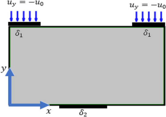
Second boundary value problem.
Figure 3.
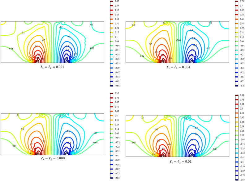
Contour plot for the displacement for different values of and (COMSOL Multiphysics).
The mathematical expressions for the boundary conditions in Figs. 1, 2 are given here demonstrating the corresponding Dirichlet boundary conditions. Note that on the other boundaries, the Neumann boundary condition is applied being zero external tractions ().
Figure 1.
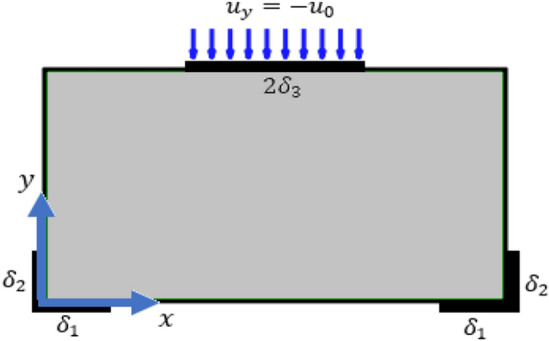
First boundary value problem.
1) Boundary conditions for the first boundary value problem:
| 31 |
2) Boundary conditions for the second boundary value problem:
| 32 |
Numerical results
The boundary value problem, i.e. Equations (26–30) with the corresponding boundary conditions (31) and (32), are numerically solved using the finite element method. For this purpose, the COMSOL Multiphysics36,37 is used for the numerical treatment of the boundary value problem. It is noted that, similar to the other generalized continua, the RMM is not available in the finite element software such as COMSOL Multiphysics, and the boundary value problem should be implemented to use the software as a solver to the system of partial differential equations. In the absence of experimental data, the behavior of the solution and the results are interpreted qualitatively.
The material constants
The material constants given in the Table 1 are used for the analysis of the plane. A more realistic input values necessities the homogenization of the heterogeneous microstructure38.
Table 1.
The material properties.
| Dimension of square | , |
|---|---|
| Density | |
| Lame’s coefficients | , |
| Lame’s coefficients | , |
| Length scales | |
| The rule of mixture | |
| Coupling moduli |
In order to implement the system of Eqs. (26–30), they are expressed in the following matrix form
| 33 |
where
Insertion of the coefficients of the matrix Eq. (33) and specifying the boundary conditions in COMSOL Multiphysics are performed considering the built-in tools in the software. The numerical solution is then carried out using the solver of the software while the convergence is achieved with sufficient number of triangular elements.
The first boundary value problem
For numerical simulation in the first boundary value problem, we choose the following values for the applied displacement at the boundary.
| 34 |
We also consider vanishing coupling parameters and (i.e. ) while the length scale parameters take the values .
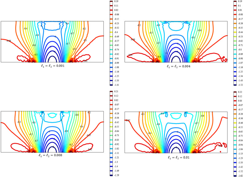
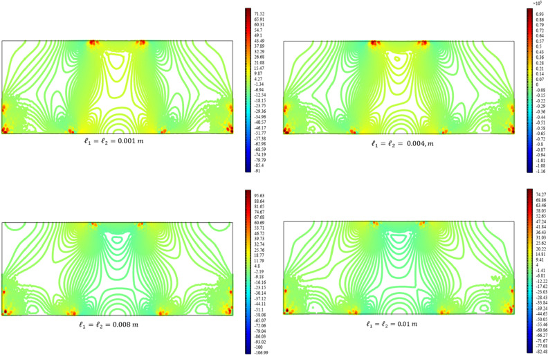
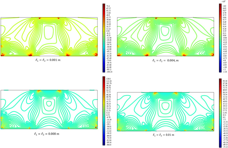
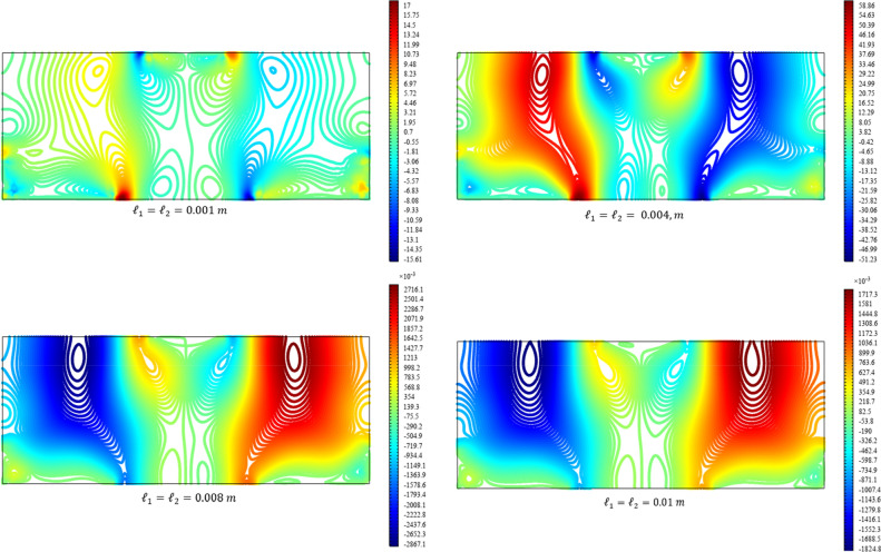
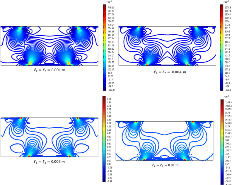
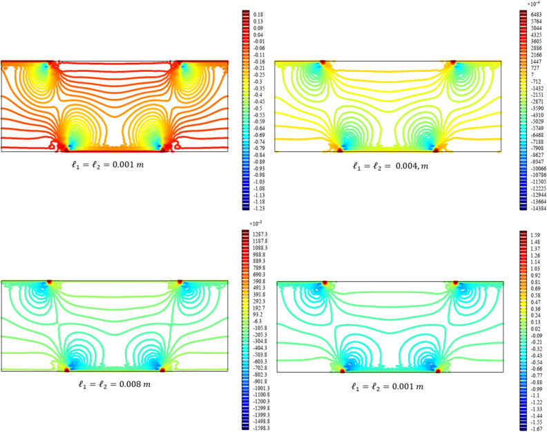
Figures 3, 4, 5, 6, 7 show the contour plot for the internal fields , , , , and , respectively. The results are normalized with and . The latter normalization is motivated by the form of the free energy. For colors in the figures, refer to the electronic version of the paper.
Figure 4.
Contour plot for the displacement for different values of and (COMSOL Multiphysics).
Figure 5.
Contour plot for the micro-strain for different values of and (COMSOL Multiphysics).
Figure 6.
Contour plot for the micro-strain for different values of and (COMSOL Multiphysics).
Figure 7.
Surface plot for the micro-strain for different values of and (COMSOL Multiphysics).
All boundary conditions, including both Neumann and Dirichlet conditions, are satisfied. The symmetry and anti-symmetry expected for the corresponding deformation measures are confirmed in the results presented in the figures. Interestingly, the and components of micro-strain appear only in the vicinity of the displaced boundaries while the component of the micro-strain, similar to the displacements and , is distributed over the entire domain.
Reducing the length scale parameters and , as expected, eliminates the nonclassical measures i.e. micro-strains. It is noted that setting the length scale parameters and equal to zero cancels the effect of the gradient of the micro-strain. In this case, with vanishing and , the RMM reduces to the classical model of elasticity for which the numerical treatment developed here is to be reformulated and replaced by the finite element for classical elasticity.
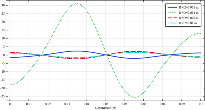
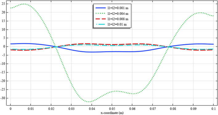
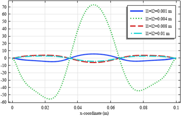
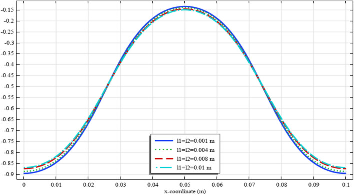
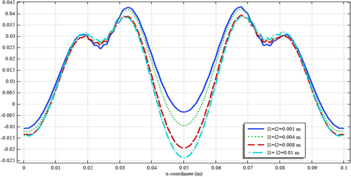
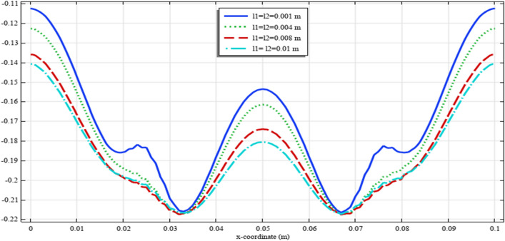
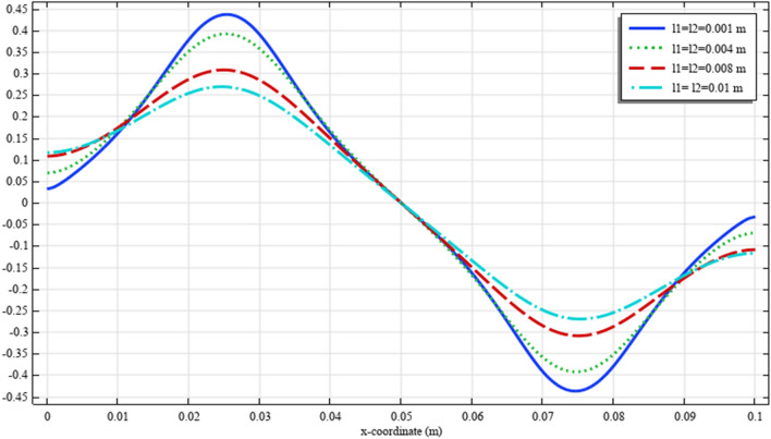
To elaborate the deformation pattern in the plane, the displacement and micro-strain components are demonstrated in Figs. 8, 9, 10, 11, 12 along the mid-line . It is observed that the length scale parameter has a greater effect on micro-strain rather than the displacement components. It is also observed that the displacement component , the micro-strain component and the micro-strain component possess even symmetry about the central point , while the other components depict odd symmetry.
Figure 8.
The displacement for different values of and (COMSOL Multiphysics).
Figure 9.
The displacement for different values of and (COMSOL Multiphysics).
Figure 10.
The micro-strain for different values of and (COMSOL Multiphysics).
Figure 11.
The micro-strain for different values of and (COMSOL Multiphysics).
Figure 12.
The micro-strain for different values of and (COMSOL Multiphysics).
The second boundary value problem
For the numerical simulation of the second boundary value problem, the following values are selected for the applied displacement at the boundary.
| 35 |
Considering these values together with , the internal fields of the RMM plane are obtained.
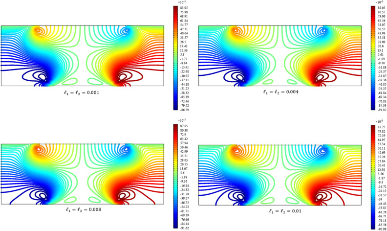
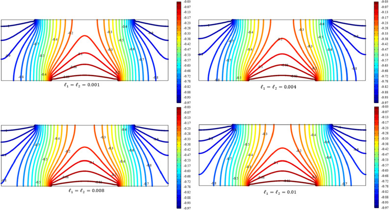
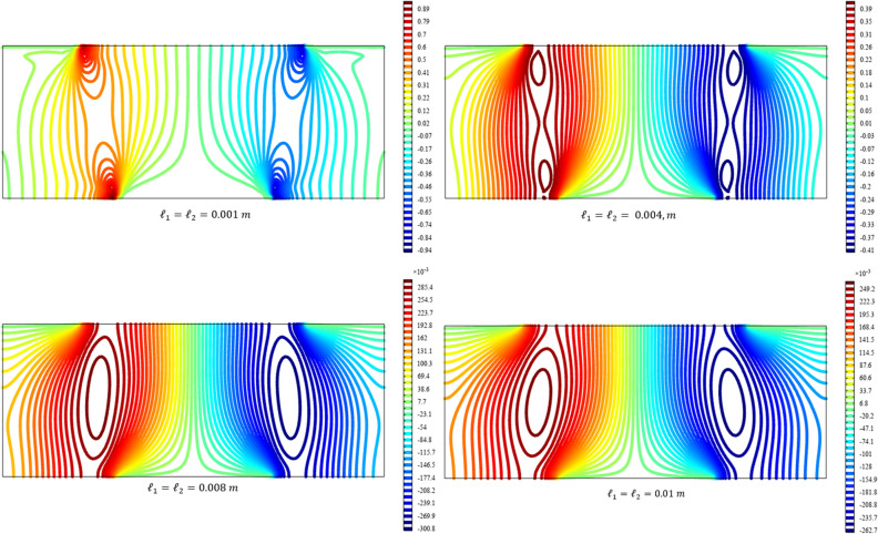
Figures 13, 14, 15, 16, 17 show the contour plot for the internal fields , , , , and , respectively. Similar to the first BVP, the micro-strain vanishes when reducing the length scale parameters l1 and l2. Moreover, the and components of micro-strain only appears in the neighborhood of the external excitation while the component of micro-strain is distributed over the entire domain.
Figure 13.
Contour plot for the displacement for different values of and (COMSOL Multiphysics).
Figure 14.
Contour plot for the displacement for different values of and (COMSOL Multiphysics).
Figure 15.
Contour plot for the micro-strain for different values of and (COMSOL Multiphysics).
Figure 16.
Contour plot for the micro-strain for different values of and (COMSOL Multiphysics).
Figure 17.
Contour plot for the micro-strain for different values of and (COMSOL Multiphysics).
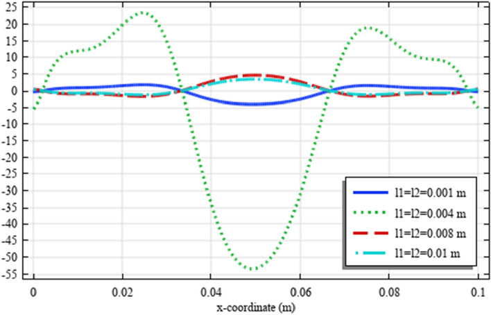
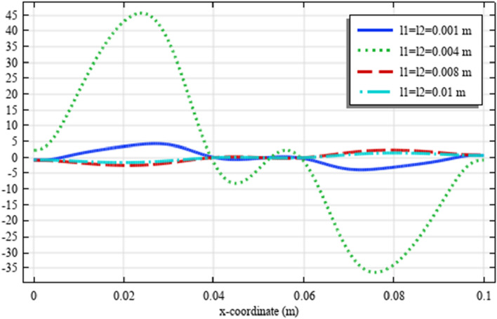
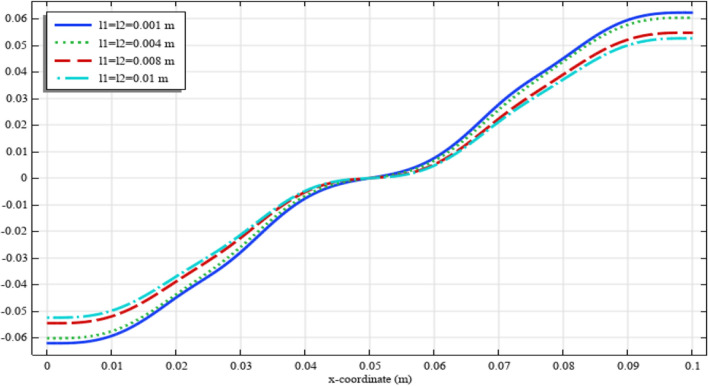
Figures 18, 19, 20, 21, 22 show the displacement and micro-strain fields of the homogenized domain along the midline with changing the parameter and while . It is again noticed that the nonclassical quantities, i.e. micro-strains, are considerably affected with the variation of the length scales.
Figure 18.
The displacement for different values of and (COMSOL Multiphysics).
Figure 19.
The displacement for different values of and (COMSOL Multiphysics).
Figure 20.
The micro-strain for different values of and (COMSOL Multiphysics).
Figure 21.
The micro-strain . for different values of and (COMSOL Multiphysics).
Figure 22.
The micro-strain for different values of and (COMSOL Multiphysics).
Conclusion
In this article, the reduced micromorphic model is used for the static analysis of a plane. The variational method is used to get the field equations and boundary conditions for the proposed quantities. The main difference between the present model and the classical model is the set of the deformation measures including classical strain tensor, micro-strain tensor, and residual strain tensor. One of the proposed quantities, micro-strain tensor, is used as a measure of the internal interaction of microelements due to the externally applied fields.
The governing equations and the specified boundary conditions were introduced in Cartesian coordinates to describe a rectangular domain. The numerical solution based on the finite element method were derived using the COMSOL Multiphysics. In order to elaborate the material behavior in the reduced micromorphic model, two case studies were discussed. The first case was a rectangular plane possessing one displaced boundary and two supports while the second case was a rectangular plane with two displaced boundaries and one support. The results are illustrated graphically and discussed. The most admissible results are that the micro-strain tensor is concentrated around the displaced boundary and supports while the displacement is distributed uniformly over the entire domain of the solution.
In future studies, specific microstructures/microarchitectures will be considered and homogenized computationally towards reduced micromorphic model. The deformation patterns obtained in this study can be used for the identification of the microarchitectures whose behavior can be captured by reduced micromorphic model. Furthermore, in the context of laboratory experiments and based on digital image correlation, the results of this study (in particular the contours of the field quantities) can also guide for identifying the heterogenous materials whose behavior can be well described with reduced micromorphic model.
Acknowledgements
S.M.M acknowledges the financial support by the Starting Grant (2018-03636) from the Swedish Research Council (Vetenskapsrådet).
Abbreviations
Displacement components
Classical strain tensor
Micro-strain tensor
Micro-stress tensor
Cauchy-like tensor or residual stress tensor
Higher order stress tensor
- and
Macroscopic mass density and mass density of a material particle
Micro-inertia
Body force
Body higher-order moment
Cauchy stress vector
Higher stress tensor
Wedge forces at the corners
- and
Elastic moduli of the microstructure,
- and
Elastic moduli of the matrix material.
- and
Elastic moduli for coupling between micro-strain and macro-strain
- and
Length scale parameters
- and
Height and width of the rectangle domain
Author contributions
A. R. El Dhaba carried out the formulation. Both authors contributed to the simulation, interpretation, discussion, and writing of the manuscript.
Funding
Open access funding provided by Uppsala University.
Competing interests
The authors declare no competing interests.
Footnotes
Publisher's note
Springer Nature remains neutral with regard to jurisdictional claims in published maps and institutional affiliations.
References
- 1.Eringen AC. Balance laws of micromorphic continua revisited. Int. J. Eng. Sci. 1992;30:805–810. doi: 10.1016/0020-7225(92)90109-T. [DOI] [Google Scholar]
- 2.Eringen AC. Simple microfluids. Int. J. Eng. Sci. 1964;2:205–217. doi: 10.1016/0020-7225(64)90005-9. [DOI] [Google Scholar]
- 3.Eringen AC. Balance laws of micromorphic mechanics. Int. J. Eng. Sci. 1970;8:819–828. doi: 10.1016/0020-7225(70)90084-4. [DOI] [Google Scholar]
- 4.Eringen AC, Maugin GA. Electrodynamics of Continua I. Springer-Verlag; 1990. [Google Scholar]
- 5.Madeo, A., Neff, P., Ghiba, I.D., Placidi, L., Rosi, G. Band gaps in the relaxed linear micromorphic continuum. ZAMM Zeitschrift fur Angew. Math. und Mech. 95, 880–887 (2015). 10.1002/zamm.201400036
- 6.Tian X, Xu M, Deng Q, Sladek J, Sladek V, Repka M, Li Q. Size-dependent direct and converse flexoelectricity around a micro-hole. Acta Mech. 2020;231:4851–4865. doi: 10.1007/s00707-020-02792-7. [DOI] [Google Scholar]
- 7.Eringen AC. Linear theory of nonlocal elasticity and dispersion of plane waves. Int. J. Eng. Sci. 1972;10:425–435. doi: 10.1016/0020-7225(72)90050-X. [DOI] [Google Scholar]
- 8.Eringen, A. Nonlocal Continuum Field Theories. Springer (2004)
- 9.Mindlin RD. Micro-structure in linear elasticity. Arch. Ration. Mech. Anal. 1964;16:51–78. doi: 10.1007/BF00248490. [DOI] [Google Scholar]
- 10.Mindlin RD, Eshel NN. On first strain-gradient theories in linear elasticity. Int. J. Solids Struct. 1968;4:109–124. doi: 10.1016/0020-7683(68)90036-X. [DOI] [Google Scholar]
- 11.Mindlin, R.D. Second gradient of strain and surface-tension in linear elasticity, Int. J. Solids Struct. 1, 417-438 (1965).
- 12.Théorie des Corps déformables Cosserat, E. & C.F. Nature. 1909;81:67–67. doi: 10.1038/081067a0. [DOI] [Google Scholar]
- 13.Experiments and theory in strain gradient elasticity Lam, D.C.C., Yang, F., Chong, a. C.M., Wang, J., Tong, P. J. Mech. Phys. Solids. 2003;51:1477–1508. doi: 10.1016/S0022-5096(03)00053-X. [DOI] [Google Scholar]
- 14.Yvonnet, J. Computational Homogenization of Heterogeneous Hyperelastic Materials. Springer International Publishing (2013)
- 15.Molavitabrizi, D., Mousavi, S.M. Elasticity of anisotropic low-density lattice materials. J. Eng. Mater. Technol. 143, (2021). 10.1115/1.4048931
- 16.Monchiet, V., Auffray, N., Yvonnet, J. Strain-gradient homogenization: aA bridge between the asymptotic expansion and quadratic boundary condition methods. Mech. Mater. 143, (2020). 10.1016/j.mechmat.2019.103309
- 17.Yang H, Abali BE, Timofeev D, Müller WH. Determination of metamaterial parameters by means of a homogenization approach based on asymptotic analysis. Contin. Mech. Thermodyn. 2020;32:1251–1270. doi: 10.1007/s00161-019-00837-4. [DOI] [Google Scholar]
- 18.Desmoulins A, Kochmann DM. Local and nonlocal continuum modeling of inelastic periodic networks applied to stretching-dominated trusses. Comput. Methods Appl. Mech. Eng. 2017;313:85–105. doi: 10.1016/j.cma.2016.09.027. [DOI] [Google Scholar]
- 19.Rizzi, G., Dal Corso, F., Veber, D., Bigoni, D. Identification of second-gradient elastic materials from planar hexagonal lattices. Part I: Analytical derivation of equivalent constitutive tensors. Int. J. Solids Struct. 176–177, 1–18 (2019). 10.1016/j.ijsolstr.2019.07.008
- 20.Barchiesi, E., dellIsola, F, Laudato, M., Placidi, L., Seppecher, P. A 1D Continuum Model for Beams with Pantographic Microstructure : Asymptotic Micro-Macro Identification and Numerical Results. In: Advances in Mechanics of Microstructured Media and Structures. Springer (2018).
- 21.Neff P, Ghiba ID, Madeo A, Placidi L, Rosi G. A unifying perspective: The relaxed linear micromorphic continuum. Contin. Mech. Thermodyn. 2014;26:639–681. doi: 10.1007/s00161-013-0322-9. [DOI] [Google Scholar]
- 22.Shaat M. A reduced micromorphic model for multiscale materials and its applications in wave propagation. Compos. Struct. 2018;201:446–454. doi: 10.1016/j.compstruct.2018.06.057. [DOI] [Google Scholar]
- 23.Eringen AC. Nonlocal continuum mechanics based on distributions. Int. J. Eng. Sci. 2006;44:141–147. doi: 10.1016/j.ijengsci.2005.11.002. [DOI] [Google Scholar]
- 24.Khurana A, Bala S, Khan H, Tomar SK, Neff P. On the dispersion of waves for the linear thermoelastic relaxed micromorphic model. J. Therm. Stress. 2020;43:3–20. doi: 10.1080/01495739.2019.1679056. [DOI] [Google Scholar]
- 25.Aivaliotis, A., Tallarico, D., Daouadji, A., Neff, P., Madeo, A. Scattering of finite-size anisotropic metastructures via the relaxed micromorphic model. 1–28 (2019)
- 26.Madeo, A., Collet, M., Miniaci, M., Billon, K., Ouisse, M., Neff, P. Modeling real phononic crystals via the weighted relaxed micromorphic model with free and gradient micro-inertia. Journal of Elasticity 130, 59–83 (2018).
- 27.Barbagallo G, Tallarico D, D’Agostino MV, Aivaliotis A, Neff P, Madeo A. Relaxed micromorphic model of transient wave propagation in anisotropic band-gap metastructures. Int. J. Solids Struct. 2019;162:148–163. doi: 10.1016/j.ijsolstr.2018.11.033. [DOI] [Google Scholar]
- 28.Shaat M, El Dhaba AR. On the equivalent shear modulus of composite metamaterials. Compos. Part B Eng. 2019;172:506–515. doi: 10.1016/j.compositesb.2019.05.056. [DOI] [Google Scholar]
- 29.El Dhaba AR. Reduced micromorphic model in orthogonal curvilinear coordinates and its application to a metamaterial hemisphere. Sci. Rep. 2020;10:2846. doi: 10.1038/s41598-020-59696-8. [DOI] [PMC free article] [PubMed] [Google Scholar]
- 30.Shaat M, Ghavanloo E, Emam S. A Micromorphic Beam Theory for Beams with Elongated Microstructures. Sci. Rep. 2020;10:7984. doi: 10.1038/s41598-020-64542-y. [DOI] [PMC free article] [PubMed] [Google Scholar]
- 31.Rizzi G, Hütter G, Madeo A, Neff P. Analytical solutions of the simple shear problem for micromorphic models and other generalized continua. Arch. Appl. Mech. 2021;91:2237–2254. doi: 10.1007/s00419-021-01881-w. [DOI] [Google Scholar]
- 32.Böhmer, C.G., Lee, Y., Neff, P. Chirality in the plane. J. Mech. Phys. Solids. 134, (2020). 10.1016/j.jmps.2019.103753
- 33.Madeo, A., Neff, P., Aifantis, E.C., Barbagallo, G., D’Agostino, M.V. On the role of micro-inertia in enriched continuum mechanics. Proc. R. Soc. A Math. Phys. Eng. Sci. 473, (2017). 10.1098/rspa.2016.0722 [DOI] [PMC free article] [PubMed]
- 34.Placidi L, El Dhaba AR. Semi-inverse method à la Saint-Venant for two-dimensional linear isotropic homogeneous second-gradient elasticity. Math. Mech. Solids. 2017;22:919–937. doi: 10.1177/1081286515616043. [DOI] [Google Scholar]
- 35.El-Dhaba AR. Semi-inverse method for a plane strain gradient orthotropic elastic rectangle in tension. Microsyst. Technol. 2018;24:1317–1331. doi: 10.1007/s00542-017-3508-4. [DOI] [Google Scholar]
- 36.COMSOL Multiphysics, COMSOL: Structural Mechanics Module. (2008)
- 37.COMSOL Multiphysics v. 5.4. COMSOL AB, Stockholm, Sweden.
- 38.Neff P, Eidel B, d’Agostino MV, Madeo A. Identification of Scale-Independent Material Parameters in the Relaxed Micromorphic Model Through Model-Adapted First Order Homogenization. J. Elast. 2020;139:269–298. doi: 10.1007/s10659-019-09752-w. [DOI] [Google Scholar]


