

Abstract
Purpose There is a lack of quantitative research that describes the alignment and, more importantly, the effects of malalignment on total wrist arthroplasty (TWA). The main goal of this pilot study was to assess the alignment of TWA components in radiographic images and compare them with measures computed by three-dimensional analysis. Using these measures, we then determined if malalignment is associated with range of motion (ROM) or clinical outcomes (PRWHE, PROMIS, QuickDash, and grip strength).
Methods Six osteoarthritic patients with a single type of TWA were recruited. Radiographic images, computed tomography images, and clinical outcomes of the wrists were recorded. Using posteroanterior and lateral radiographs, alignment measurements were defined for the radial and carpal components. Radiographic measurements were validated with models reconstructed from computed tomography images using Bland–Altman analysis. Biplanar videoradiography (<1mm and <1 degree accuracy) was used to capture and compute ROM of the TWA components. Linear regression assessed the associations between alignment and outcomes.
Results Radiographic measures had a 95% limit-of-agreement (mean difference ± 1.96 × SD) of 3 degrees and 3mm with three-dimensional values, except for the measures of the carpal component in the lateral view. In our small cohort, wrist flexion–extension and radial–ulnar deviation were correlated with volar–dorsal tilt and volar–dorsal offset of the radial component and demonstrated a ROM increase of 3.7 and 1.6 degrees per degree increase in volar tilt, and 10.8 and 4.2 degrees per every millimeter increase in volar offset. The carpal component's higher volar tilt was also associated with improvements in patient-reported pain.
Conclusions We determined metrics describing the alignment of TWA, and found the volar tilt and volar offset of the radial component could potentially influence the replaced wrist's ROM.
Clinical Relevance TWA component alignment can be measured reliably in radiographs, and may be associated with clinical outcomes. Future studies must evaluate its role in a larger cohort.
Keywords: alignment, arthroplasty, outcomes, wrist, volar tilt
There is a lack of quantitative research that describes alignment and its potential influence on the functional and clinical outcomes after total wrist arthroplasty (TWA). The optimal alignment of a TWA implant is not defined in the literature, and there is no consensus on the ideal methodology to radiologically assess this alignment. 1 2 In previous works, one study focused on the surgeon's ability to align the implants during surgery, 1 while another defined the alignment only for a single prosthesis that is no longer commercially available. 2 The current generation of TWA designs, 3 4 5 6 which have evolved to improve implant stability, feature either a toroidal or ellipsoidal articular surface, and two screws and a central peg for fixation of the carpal component. 7 8 9 Current surgical guides recommend alignment of the radial component's stem with the longitudinal axis of the radius and alignment of the peg of the carpal component with the third metacarpal (MC3) diaphysis to achieve the ideal congruency between the articular surfaces. However, there is no available science on the consequences of deviation from these recommendations.
The aim of this in vivo pilot study was to define the alignment of TWA components in radiographic images and compare them with accurate measurements from three-dimensional (3D) computed tomography (CT) models. Then, we used these alignment measures to determine if the component alignments influence the active wrist range of motion (ROM), patient-reported outcomes, or grip strength in a small cohort of patients.
Materials and Methods
Study Subjects
Six patients with the same total wrist implant design (Freedom size 2, Integra LifeSciences, Plainsboro, NJ) were recruited into the study after institutional review board approval. All subjects were non-rheumatoid patients, and none had a prior radius fracture or malunion. All surgeries were performed by a single fellowship-trained expert 10 hand surgeon. At the time of enrollment (6–34 months postoperatively), the radiographs were assessed to assure the absence of any loosening, osteolysis, or subluxation. To assess pain and disability of the wrist, Patient-Rated Wrist-Hand Evaluation (PRWHE), 11 Patient-Reported Outcomes Measurement Information System (PROMIS Bank v1.2, Upper Extremity), 12 and Quick Disabilities of the Arm, Shoulder, and Hand ( Quick DASH) 13 were administered, and grip strength (Jamar Hand Dynamometer, Jackson, MI) was measured at the time of enrollment. Wrist ROM, our primary outcome, was computed directly from biplane videoradiography (BVR), described in detail below.
2D Alignment from Radiographs
Standard 14 posteroanterior (PA) and lateral wrist radiographs were obtained at the time of enrollment. An open-source image analysis program, Fiji, 15 was used to measure the alignment of the TWA components in each radiographic view. The alignment of the radial component was measured on PA (radial–ulnar tilt) and lateral (volar–dorsal tilt) radiographs as the angle between the longitudinal axis of the radial shaft and the stem of the radial component ( Fig. 1 , indicated by RRU and RVD, respectively). Radial tilt in the coronal plane and volar tilt in the sagittal plane was defined as positive. Radial component offset was defined as the shortest distance from the longitudinal axis of the radial shaft to the stem's location on the radial tray ( Fig. 1 , indicated by arrows in the direction of radius to radial component). Carpal component tilt in the coronal and sagittal planes was defined as the angle between the MC3 diaphysis and the carpal component's peg. The carpal component's translational offset was measured on the PA (radial–ulnar offset) and lateral (volar–dorsal offset) as the shortest distance from the MC3 diaphysis to the peg's location on the distal aspect of the carpal component's tray (directed from MC3 to carpal component). Alignment measures of left hands were mirrored for post-processing.
Fig. 1.

Posteroanterior view (PA, left panel) and lateral view (right panel) of the right hand of a subject with total wrist arthroplasty. Blue lines show the reference lines of the radial (R) and carpal components (C) and red lines show the reference lines of the third metacarpal and radius. For each component, radial tilt (+RU) and offset (perpendicular black arrows) were defined in PA view, and volar tilt (+VD) and offset (perpendicular black arrows) were defined in lateral view. In this figure, the radial and carpal components are tilted radially and dorsally.
3D Alignment from CT Images
CT volume images (80 kVp/80 mA, 0.39mm × 0.39mm × 0.625mm; Lightspeed 16, GE Medical, WI) of each wrist were acquired and segmented to obtain 3D models of the carpal component, second metacarpal (MC2), MC3, fourth metacarpal (MC4), and resected radius using a previously reported threshold-based approach in Mimics (Materialise, Belgium). 16 17 The 3D model of the radial component was generated using a 3D scanner with 0.1 mm resolution (Artec Spider, Luxembourg). A presurgery model of the radius was constructed to define alignment measures and analyze kinematics (more details in Supplementary Material [online only]). 18
To define the alignments and describe the wrist motion, coordinate systems (CSs) were constructed for each TWA component, the radius, and the MC3 using previously described methodologies (more details in Supplementary Material [online only]). The radial and carpal component CSs were based on their geometrical features ( Fig. 2A, B ), and the radius CS was defined using its anatomical features ( Fig. 2C ). 19 The MC3 CS was defined using both MC2 and MC4 ( Fig. 2D ). 20
Fig. 2.

The orthogonal coordinate systems for the ( A ) radial component, ( B ) carpal component, ( C ) resected radius, and ( D ) the third metacarpal are shown as red (x-axis), green (y-axis), and blue (z-axis).
The 3D alignment measurements were defined computationally and automatically based on the relative alignment of the TWA components to the bone CSs. The relative orientations of the individual implant components to their respective bones were calculated using the scalar product of the x-axes and y-axes for radial and volar tilt, respectively. For example,
The translational offsets were measured as the distance between the location of the CS of the components and the bones in all directions. These descriptions correspond to the metrics in the plain film-measured alignments.
Clinical Outcomes
PRWHE, PROMIS, and Quick DASH total scores were calculated according to their published guidelines. 11 12 13 Grip strengths were normalized to account for age, sex, and handedness ( Supplementary Material S5 [online only]) before processing, based on the data provided in the device's guidelines.
TWA Kinematics and Range-of-Motion (Biplane Videoradiography)
Dynamic implant motion was calculated using a previously-described BVR system 16 (imaging parameters: 75 kV/80 mA, 200Hz, 500µs shutter speed). BVR combines implant-specific image volumes with movement data from videoradiographs to produce kinematics of the replaced joint with submillimeter and subdegree accuracy. Each study participant performed three active anatomical tasks of flexion–extension, radial–ulnar deviation, and circumduction. Patients were instructed and trained to attempt their full ROM in each task. The implants were tracked using an open-source 2D–3D registration software (Autoscoper, https://simtk.org/projects/autoscoper) with methodology that has been described previously. 17
The position and orientation of the TWA components were transformed into the radius and MC3 reference frames, and wrist motion was described as the motion of MC3 in the radius CS, relative to the wrist neutral position. The neutral position was defined as the position in which the MC3 CS had the least deviation from the radius CS, across all tasks. The helical axis of motion (HAM) method was used to describe the wrist kinematics, and ROM was computed as the maximum wrist rotation in each direction of flexion, extension, radial deviation, and ulnar deviation among all tasks. Flexion–extension and radial–ulnar deviation were calculated by projecting HAM rotations to the radius CS.
Statistical Analysis
Radiographic alignments were assessed three separate times by two raters, who were blinded to the clinical outcomes. For each rater, intraclass correlation coefficient (ICC) estimates and their 95% confidence intervals were calculated based on a single-rater, absolute-agreement, two-way mixed-effects model. 21 The inter-rater agreement was assessed using Pearson's correlation coefficient (Pearson's r ). Bland–Altman plot was used to evaluate the agreement of the radiographic measurements compared with the 3D model alignment measurements by determining the bias (average differences between methods) and 95% limit of agreement of the measurements (bias ± 1.96 × standard deviation). 22 Linear regressions, with α set to 0.10 due to the small sample size, were used to evaluate the association of component alignment, as measured on the 3D models, to the observed clinical outcomes and ROM. With α set to 0.10, we had 60 to 85% power to detect R 2 of 0.55 to 0.76.
Results
Six osteoarthritic patients (75 ± 6 years, 2 females, 2 right wrists) were enrolled, with reported PRWHE, PROMIS, and Quick DASH scores of 16 ± 21, 50 ± 10, and 24 ± 26, respectively ( Table 1 ). Overall, patients demonstrated 49.2 ± 8.4 degrees of extension, 26.6 ± 12.6 degrees of flexion, 16.8 ± 4.7 degrees of radial deviation, and 18.2 ± 10.4 degrees of ulnar deviation ROM as measured by BVR. There were no significant associations between the follow-up time and any of the ROMs ( p > 0.05).
Table 1. Clinical outcomes (pain scores and grip strength) and maximum range-of-motion capability of 6 nonrheumatoid patients with Freedom wrist. A higher score for PROMIS demonstrates better outcomes (maximum score is 56.4), while a lower score for PRWHE and Quick DASH depict a better outcome. See Methods and supplementary materials for a description of grip strength normalization .
| # | Gender | Age | Follow-up time (mo) | Side-dom. | Grip strength (kg) | Normalized grip strength | PRWHE | PROMIS | Quick DASH | Active extension (deg) | Active flexion (deg) | Active radial dev. (deg) | Active ulnar dev. (deg) |
|---|---|---|---|---|---|---|---|---|---|---|---|---|---|
| 1 | Male | 69 | 16 | Right-D | 22.0 | –2.1 | 46.5 | 35.1 | 43.2 | 43.4 | 25.4 | 16.6 | 11.6 |
| 2 | Female | 74 | 34 | Left-ND | 19.1 | 0.1 | 0 | 56.4 | 2.3 | 48.4 | 49.3 | 13.7 | 29.1 |
| 3 | Female | 78 | 32 | Right-D | 15.0 | –0.8 | 38 | 37.3 | 59.1 | 50.7 | 23.9 | 14.2 | 20.7 |
| 4 | Male | 70 | 14 | Left-D | 24.6 | –1.0 | 0 | 56.4 | 0 | 54.8 | 25.1 | 23.2 | 9.8 |
| 5 | Male | 74 | 31 | Left-D | 25.4 | –0.9 | 12.5 | 56.4 | 36.4 | 37.0 | 10.4 | 21.6 | 6.7 |
| 6 | Male | 85 | 6 | Left-ND | 38.7 | 1.8 | 0 | 56.4 | 2.3 | 60.8 | 25.6 | 11.5 | 31.2 |
| Average (SD) | – | 75.0 (5.9) |
22.1 (11.6) | – | 24.1 (8.1) |
–0.5 (1.3) |
16.2 (20.9) |
49.7 (10.5) |
23.9 (25.6) |
49.2 (8.4) |
26.6 (12.6) |
16.8 (4.7) |
18.2 (10.4) |
Abbreviations: D, dominant hand; ND, nondominant hand; PROMIS; Patient-Reported Outcomes Measurement Information System; PRWHE; Patient-Rated Wrist-Hand Evaluation; QuickDash; Quick Disabilities of the Arm, Shoulder, and Hand; SD, standard deviation.
Note: Grip strength data were normalized using a population data provided in the guideline of the Jamar Hand Dynamometer.
Radiographic Measurements Validity
The plain radiographic measurements differed by less than 1 degree and 1 mm, and had 95% limits of agreements within 3 degrees and 3 mm of the 3D alignment measurements ( Table 2 ) in all except the sagittal alignment measurements of the carpal component (4.4 degrees and -4.0mm bias, respectively). For each rater, the intrarater reliability of radiographic measurement was highest for the radial component's alignment measures in both PA and lateral radiographic views (ICC > 0.90). The carpal component's alignment measures also had high intra-rater reliability in the PA view (ICC > 0.95); however, the intra-rater reliability was only moderate for these measures in the lateral view (0.50 < ICC < 0.85). The inter-rater agreement was high for both radial and carpal component measures (Pearson's r > 0.85) except for the carpal component's offset measure in the lateral view (Pearson's r = 0.49).
Table 2. The difference between radiographic and three-dimensional measurements demonstrated submillimeter and subdegree biases (mean differences) except for the measures calculated between the carpal component and third metacarpal.
| Implant's component | Alignment measurement | Bias of methods | 95% limits of agreement of methods |
|---|---|---|---|
| Radial component | Volar/dorsal tilt | 0.4 deg | –3.1–3.9 |
| Radial/ulnar tilt | 0.6 deg | –1.9–3.1 | |
| Volar/dorsal offset | –0.6 deg | –3.7–2.6 | |
| Radial/ulnar offset | 0.9 deg | –0.5–2.2 | |
| Carpal component | Volar/dorsal tilt | 4.4 mm | –3.8–12.7 |
| Radial/ulnar tilt | –0.9 mm | –4.7–2.9 | |
| Volar/dorsal offset | –4.0 mm | –6.2– –1.7 | |
| Radial/ulnar offset | 0.7 mm | –1.7–3.1 |
The component alignments with the bony anatomy varied widely in our cohort, with the lowest component alignment variation (<2mm) in the volar–dorsal offset of the radial component ( Table 3 ). The radial component's alignment ranged from 3.2 dorsal to 6.1 degrees volar tilt, and from 2.8 ulnar to 20.0 degrees radial tilt, while the carpal component ranged from 13.6 dorsal to 9.2 degrees volar tilt, and from 2.9 ulnar to 12.0 degrees radial tilt ( Table 3 ). Within the alignment measures, there was an association between increased volar tilt and increased volar offset of the radial component ( p < 0.05, R 2 = 0.93).
Table 3. Carpal component and radial component alignment defined from the 3D models for all subjects. Each component's alignment is defined by angular parameters of volar (+)/dorsal (−) tilt (VDT), radial (+)/ulnar (−) tilt (RUT), and translational offset parameters of radial (+)/ulnar (−) offset (RUO) and volar (+)/dorsal (−) offset (VDO).
| Subject no. | Carpal component alignment | Radial component alignment | ||||||
|---|---|---|---|---|---|---|---|---|
| VDT (deg) | RUT (deg) | RUO (mm) | VDO (mm) | VDT (deg) | RUT (deg) | RUO (mm) | VDO (mm) | |
| 1 | −13.6 | 9.3 | −5.3 | 11.6 | −0.3 | 20.0 | 8.4 | −3.2 |
| 2 | 1.7 | 12.0 | −4.3 | 7.1 | 6.1 | 2.4 | 5.1 | −1.4 |
| 3 | −3.8 | 5.9 | −6.4 | 5.5 | 1.0 | −3.4 | −1.8 | −2.6 |
| 4 | 4.6 | 2.6 | −8.5 | 6.3 | −2.6 | 2.6 | 2.1 | −4.3 |
| 5 | 9.2 | -2.9 | −2.5 | 2.2 | −3.2 | 8.4 | 3.7 | −4.7 |
| 6 | 4.6 | 6.7 | −1.4 | 6.3 | 4.4 | −2.8 | 0.1 | −2.2 |
| Average (SD) | 0.5 (8.1) | 5.8 (4.7) | −5 (2.6) | 6.5 (3.4) | 0.9 (3.7) | 4.5 (8.7) | 4.2 (3.8) | −3.1 (1.3) |
Abbreviations: 3D, three-dimensional; SD, standard deviation.
Radial Component Alignment and Outcomes
Comparing the component alignment to the clinical outcomes, increased flexion, radial deviation, and ulnar deviation ROM correlated with increased volar tilt and volar offset of the radial component. Greater volar tilt of the radial component was significantly associated with increased flexion ( p = 0.06, r = 0.55), radial deviation ( p = 0. 002, r = 0.91), and ulnar deviation ( p = 0. 02, r = 0.73) ROMs. Larger volar offset of the radial component was also associated with increases in these ROMs ( p = 0.05, 0.009, an 0.01, respectively). There was no significant association between maximum extension ROM and volar tilt or offset (p > 0.30). There was also no significant association between radial component's alignment measurements and normalized grip strength, or patient-reported outcomes ( p > 0.10).
Total flexion–extension and radial–ulnar deviation ROM were also associated with the volar tilt of the radial component and had 3.7 and 1.6 degrees larger ROM per each degree increase of volar tilt, respectively ( Fig. 3 ; R 2 = 0.58 and 0.76). Similarly, total flexion–extension and radial–ulnar deviation were associated with the volar–dorsal offset of the radial component, with a ROM increase of 10.8 and 4.2 degrees per millimeter rise of volar offset, respectively ( Fig. 4 ; R 2 = 0.55 and 0.57).
Fig. 3.
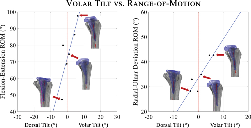
Overall flexion–extension and radial–ulnar deviation range of motion (ROM) increases as the volar tilt of the radial component increases. Reconstructions from computed tomography scan illustrate alignments of indicated data points. An increase of 3.7 degrees flexion–extension and 1.6 degrees radial–ulnar deviation with each degree increase of volar tilt.
Fig. 4.

Overall flexion–extension and radial–ulnar deviation range of motion (ROM) increases as the volar offset of the radial component increases. An increase of 10.8 degrees flexion–extension and 4.2 degrees radial–ulnar deviation for every millimeter increase of volar offset was observed.
Carpal Component Alignment and Outcomes
Greater radial tilt of the carpal component was correlated with increased wrist flexion ( p = 0.03, r = 0.67), but there was no correlation between the radial tilt of the carpal component and other ROM directions ( p > 0.10). Both PRWHE and PROMIS clinical scores were associated with higher volar tilt of the carpal component at our follow-up time points ( p = 0.04 and p = 0.01). There was no correlation between the carpal component's alignment measurements and the Quick DASH or normalized grip strength ( p > 0.10).
Discussion
In this study, we demonstrated that manual measurement of radiographic alignment of TWA components on plain radiographs correlated well with computed 3D measurement of alignment. These parameters were validated for only the Freedom TWA design, but we believe they are applicable to currently-approved TWA designs with similar design features. We also identified a potential association between increased wrist ROM and increased volar tilt and offset of the radial component, which demonstrates the alignment parameters might influence the clinical outcomes for patients. Although our cohort was small and we did not have access to preoperative information to infer a broad case for volar tilt of the implant, this potential association suggests there may be value in larger cohort studies with more focus on the alignment measures.
Restoration of normal alignment during arthroplasty surgery has been demonstrated to lead to increased success of hip, 23 knee, 24 25 and ankle arthroplasties 26 ; however, no evidence-based alignment parameters exist for TWA. The optimal implant alignment recommendations for hip and knee implants have evolved over time and have been informed by rigorous biomechanical and clinical studies. TWA biomechanical investigations are more difficult to perform due to fewer patients and the lack of established methodologies to study the prosthesis in vivo. In a cadaveric study, Ocampos investigated the alignment of the Re-Motion TWA design (Stryker, Kalamazoo, MI), and found inconsistency in the positioning of the prostheses and large variation in their alignment. 1 We also observed large variations in implant alignment, demonstrating the need to define such parameters for TWA implant during the surgery. In addition, careful attention to correct sizing of the implant and the quality of the bone in which the implant is being placed may have an influence on implant alignment in the perioperative period. In this study, we addressed the lack of TWA alignment definition using an open-source program, Fiji, 15 to assess multiple alignment measurements and validated their robustness and accuracy using a 3D modeling technique as a first step for further investigation on the role of implant alignment on patient outcomes and motion. Finally, the high correlation of volar tilt and volar offset of the radial component with each other is potentially due to the initial placement of the broach in the volar half of the distal radius rather than along the central axis of the radial diaphysis and impaction perpendicular to the natural volar tilt or the subtle shift of the impacted implant once the distal tip starts to impinge against the opposite dorsal cortex forcing a translation volarly of the proximal implant itself during seating.
Our limited dataset suggests an association between the sagittal alignment parameters of the radial component and increased flexion, radial, and ulnar deviation. No evidence of subluxation of the components throughout the ROM was observed; thus, the alignment variations are possibly affecting the ROM by potentially changing the soft tissue constraints or causing impingement. Similarly, although our observations of no significant associations may be affected by our sample size, there was no association between wrist extension and alignment parameters ( p > 0.10) possibly suggesting the role of constraints of the soft-tissue envelope of the wrist (e.g., postsurgical scar or surgical bed changes) as the limiting factor, in addition to the geometry of the implant. However, there is no objective means to quantify those soft-tissue contributions. Additionally, although none of our patients reported major pain or fear of moving their wrist, factors such as kinesiophobia (i.e., limited ROM due to fear of dislocating the implant) might also affect the range of extension in patients.
Although some earlier TWA designs accounted for the native volar tilt of the radius as a design feature, 27 the Freedom implant's radial component has a neutral 0 degree volar tilt possibly to favor wrist extension. This built-in bias indeed favors wrist extension that is confirmed by our findings of nearly twice as much extension than flexion. This study suggests that the placement of an implant with the radial component tilted volarly may increase overall ROM and permit increased flexion. This placement change could also be used as a surrogate for a design feature that incorporates a native volar tilt of the radius. However, its long-term outcomes have to be studied. The reasons for improved patient-reported outcomes with increased carpal component volar tilt can only be speculated due to our small sample size, and could be related to both mobility and pain. While the impact of malalignment of current TWA designs on implant survival rate remains unknown, a similar investigation on the trispherical TWA design has shown the association of TWA alignment with functional clinical outcomes and durability. 2 Finally, more volar tilt and offset of the radial component might result in edge loading and possible polyethylene particle wear after certain limits; thus, it is important to study the articulation of the components in larger cohorts and with longer follow-ups to resolve these issues.
In this study, we were limited by our small sample size and the use of one type of total wrist implant. There was also a lack of preoperative or immediate postoperative information for the ROM of our patients, which hampers the interpretation of our ROM data. Despite this, we found a high correlation between alignment factors and ROM, which demonstrates that further research on the relationship between TWA design and kinematics is important. We restricted our enrollment criteria to patients with osteoarthritis, as patients with inflammatory arthritis typically have soft-tissue involvement that could confound the results of this study. Larger sample size may have helped power the study better and allowed us to perform further analysis between different alignment parameters. Lastly, we used standard PA and lateral views of the wrist to assess component alignment as orthogonal radiographic views are important to enable retrospective research of TWA designs and outcomes. A shortcoming of the lateral view is the inability to consistently identify the MC3 contours because of bony overlap; consequently, our correlation with computed 3D measurements in this view was less consistent. We continue to investigate other radiographic methods to optimize visualization of the MC3. Nonetheless, this pilot study demonstrates an intriguing association between TWA component alignment and wrist ROM and prompts additional kinematic studies to optimize articular alignment parameters and improve patient outcomes and durability.
Funding Statement
Funding The recruitment of participants, purchase of equipment, and access to facilities were feasible with partial support from the National Institutes of Health P30GM122732 (COBRE Bio-engineering Core) and a grant from the American Foundation for Surgery of the Hand (AFSH) + Goldner Award.
Footnotes
Conflict of Interest The institutions of J.J.C. and S.W.W. possess intellectual property on a total wrist implant design that was not examined in this study. A.-P.C.W. has a financial interest in a TWA design that was not examined in this study.
Supplementary Material
References
- 1.Ocampos M. Component alignment in total wrist arthroplasty: success rate of surgeons in their first cases. Acta Orthop Traumatol Turc. 2014;48(03):259–261. doi: 10.3944/AOTT.2014.3017. [DOI] [PubMed] [Google Scholar]
- 2.Figgie H E, III, Inglis A E, Straub L R, Ranawat C S. A critical analysis of alignment factors influencing functional results following trispherical total wrist arthroplasty. J Arthroplasty. 1986;1(03):149–156. doi: 10.1016/s0883-5403(86)80024-9. [DOI] [PubMed] [Google Scholar]
- 3.Badge R, Kailash K, Dickson D R. Medium-term outcomes of the Universal-2 total wrist arthroplasty in patients with rheumatoid arthritis. Bone Joint J. 2016;98-B(12):1642–1647. doi: 10.1302/0301-620X.98B12.37121. [DOI] [PubMed] [Google Scholar]
- 4.Gil J A, Kamal R N, Cone E, Weiss A-PC. High survivorship and few complications with cementless total wrist arthroplasty at a mean followup of 9 years. Clin Orthop Relat Res. 2017;475(12):3082–3087. doi: 10.1007/s11999-017-5445-z. [DOI] [PMC free article] [PubMed] [Google Scholar]
- 5.Herzberg G, Boeckstyns M, Sorensen A I. “Remotion” total wrist arthroplasty: preliminary results of a prospective international multicenter study of 215 cases. J Wrist Surg. 2012;1(01):17–22. doi: 10.1055/s-0032-1323642. [DOI] [PMC free article] [PubMed] [Google Scholar]
- 6.Reigstad O, Røkkum M. Wrist arthroplasty: where do we stand today? A review of historic and contemporary designs. Hand Surg Int J Devoted Hand Up Limb Surg Relat Res J Asia-Pac Fed Soc Surg Hand. 2014;19(02):311–322. doi: 10.1142/S0218810414300034. [DOI] [PubMed] [Google Scholar]
- 7.Halim A, Weiss A-PC. Total wrist arthroplasty. J Hand Surg Am. 2017;42(03):198–209. doi: 10.1016/j.jhsa.2016.12.004. [DOI] [PubMed] [Google Scholar]
- 8.Kennedy C D, Huang J I. Prosthetic design in total wrist arthroplasty. Orthop Clin North Am. 2016;47(01):207–218. doi: 10.1016/j.ocl.2015.08.018. [DOI] [PubMed] [Google Scholar]
- 9.Hooke A W, Pettersson K, Sagerfors M, An K-N, Rizzo M. An anatomic and kinematic analysis of a new total wrist arthroplasty design. J Wrist Surg. 2015;4(02):121–127. doi: 10.1055/s-0035-1549288. [DOI] [PMC free article] [PubMed] [Google Scholar]
- 10.Tang J B, Giddins G. Why and how to report surgeons' levels of expertise. J Hand Surg Eur Vol. 2016;41(04):365–366. doi: 10.1177/1753193416641590. [DOI] [PubMed] [Google Scholar]
- 11.Hoang-Kim A, Pegreffi F, Moroni A, Ladd A. Measuring wrist and hand function: common scales and checklists. Injury. 2011;42(03):253–258. doi: 10.1016/j.injury.2010.11.050. [DOI] [PubMed] [Google Scholar]
- 12.Brodke D J, Saltzman C L, Brodke D S. PROMIS for orthopaedic outcomes measurement. J Am Acad Orthop Surg. 2016;24(11):744–749. doi: 10.5435/JAAOS-D-15-00404. [DOI] [PubMed] [Google Scholar]
- 13.Upper Extremity Collaborative Group . Beaton D E, Wright J G, Katz J N. Development of the QuickDASH: comparison of three item-reduction approaches. J Bone Joint Surg Am. 2005;87(05):1038–1046. doi: 10.2106/JBJS.D.02060. [DOI] [PubMed] [Google Scholar]
- 14.Gilula L A, Mann F A, Dobyns J H, Yin Y.Wrist Terminology as Defined by the International Wrist Investigators' Workshop (IWIW)In:2002 10.2106/00004623-200200001-00002 [DOI] [Google Scholar]
- 15.Schindelin J, Arganda-Carreras I, Frise E. Fiji - an Open Source platform for biological image analysis. Nat Methods. 2012;9(07) doi: 10.1038/nmeth.2019. [DOI] [PMC free article] [PubMed] [Google Scholar]
- 16.Akhbari B, Morton A M, Moore D C, Weiss A-PC, Wolfe S W, Crisco J J. Accuracy of biplane videoradiography for quantifying dynamic wrist kinematics. J Biomech. 2019;92:120–125. doi: 10.1016/j.jbiomech.2019.05.040. [DOI] [PMC free article] [PubMed] [Google Scholar]
- 17.Akhbari B, Morton A M, Moore D C, Weiss A-PC, Wolfe S W, Crisco J J. Kinematic accuracy in tracking total wrist arthroplasty with biplane videoradiography using a computed tomography-generated model. J Biomech Eng. 2019;141(04):445031–445037. doi: 10.1115/1.4042769. [DOI] [PMC free article] [PubMed] [Google Scholar]
- 18.Akhbari B, Morton A M, Shah K N.Proximal-distal shift of the center of rotation in a total wrist arthroplasty is more than twice of the healthy wrist J Orthop ResPublished online May 13,2020 10.1002/jor.24717 [DOI] [PMC free article] [PubMed] [Google Scholar]
- 19.Akhbari B, Moore D C, Laidlaw D H. Predicting carpal bone kinematics using an expanded digital database of wrist carpal bone anatomy and kinematics. J Orthop Res. 2019;37(12):2661–2670. doi: 10.1002/jor.24435. [DOI] [PMC free article] [PubMed] [Google Scholar]
- 20.Coburn J C, Upal M A, Crisco J J. Coordinate systems for the carpal bones of the wrist. J Biomech. 2007;40(01):203–209. doi: 10.1016/j.jbiomech.2005.11.015. [DOI] [PubMed] [Google Scholar]
- 21.Koo T K, Li M Y. A guideline of selecting and reporting intraclass correlation coefficients for reliability research. J Chiropr Med. 2016;15(02):155–163. doi: 10.1016/j.jcm.2016.02.012. [DOI] [PMC free article] [PubMed] [Google Scholar]
- 22.Bland J M, Altman D G. Measuring agreement in method comparison studies. Stat Methods Med Res. 1999;8(02):135–160. doi: 10.1177/096228029900800204. [DOI] [PubMed] [Google Scholar]
- 23.Müller M, Duda G, Perka C, Tohtz S. The sagittal stem alignment and the stem version clearly influence the impingement-free range of motion in total hip arthroplasty: a computer model-based analysis. Int Orthop. 2016;40(03):473–480. doi: 10.1007/s00264-015-2845-0. [DOI] [PubMed] [Google Scholar]
- 24.Matsuda S, Kawahara S, Okazaki K, Tashiro Y, Iwamoto Y. Postoperative alignment and ROM affect patient satisfaction after TKA. Clin Orthop Relat Res. 2013;471(01):127–133. doi: 10.1007/s11999-012-2533-y. [DOI] [PMC free article] [PubMed] [Google Scholar]
- 25.Rivière C, Lazic S, Boughton O, Wiart Y, Vïllet L, Cobb J. Current concepts for aligning knee implants: patient-specific or systematic? EFORT Open Rev. 2018;3(01):1–6. doi: 10.1302/2058-5241.3.170021. [DOI] [PMC free article] [PubMed] [Google Scholar]
- 26.Greisberg J, Hansen S T, Digiovanni C. Alignment and technique in total ankle arthroplasty. Oper Tech Orthop. 2004;14(01):21–30. [Google Scholar]
- 27.Figgie M P, Ranawat C S, Inglis A E, Sobel M, Figgie H E. Trispherical total wrist arthroplasty in rheumatoid arthritis. J Hand Surg Am. 1990;15(02):217–223. doi: 10.1016/0363-5023(90)90098-c. [DOI] [PubMed] [Google Scholar]
Associated Data
This section collects any data citations, data availability statements, or supplementary materials included in this article.