Abstract
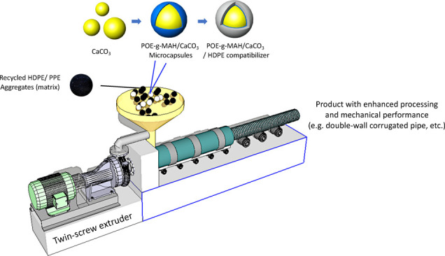
With the people’s awareness of the “3Rs” in recent years, using recycled high-density polyethylene (HDPE) and random copolymer polypropylene (PPR) as the base materials for piping fabrication has become a mainstream in scholastic path and industrial engineering. In this study, the modified maleic anhydride-grafted polyethylene (POE-g-MAH) compatibilizer was fabricated to increase the interfacial adhesion and dispersion. With the surface modification of calcium carbonate, a POE-g-MAH/CaCO3/HDPE polymer composite has been prepared. Such modified polymer composites can further reinforce the processing performance and mechanical properties of recycled HDPE and PPR materials. The results indicated that with the introduction of the polymer composite, significant enhancement of the recycled materials in the aspects of processability, tensile strength, flexural performance, and impact force could be obtained, and the POE-g-MAH/CaCO3/HDPE polymer composite would contribute to the impressive balance between high rigidity and toughness. In addition, the feasibility and mechanical properties of the recycled HDPE-PPR-POE-g-MAH/CaCO3/HDPE blended system were also studied: with the help of a composite microcapsule, the gap of mechanical capacity between recycled and non-recycled materials was further reduced, and such a blended system was capable of being commercialized in the piping industry.
1. Introduction
Double-wall corrugated pipes with a cyclic wall structure have been widely used for industrial and daily consumption. Compared with traditional iron, concrete, and even clay pipes, the double wall corrugated pipe has high rigidity, excellent bending performance, high impact and compressive strength, and even other characteristics. Because of their excellent performance and relatively economical cost,1 double-wall corrugated pipes in Europe and other developed countries have been greatly promoted and applied.2
The raw materials of double-wall corrugated pipes could be generally divided into two categories, which include polyvinyl chloride (PVC) and polyolefin (polyethylene or polypropylene).3,4 The PVC piping materials, although compared to polyolefins, have advantages of good stiffness and low-cost over the polyethylene and polypropylene ones, but because of their difficulties in processing, it would become difficult to enlarge the diameter. In addition, the PVC double wall corrugated pipe would have significant impact defects under low temperature.3,5 As in the aspect of flexibility, weldability, thickness, aging resistance, and even environmental protection, polyolefin double wall corrugated pipe polyolefin has certain advantages over polyvinyl chloride. Hence, the PVC raw material has been substituted by polyolefin in the market due to the fierce competition.6 Polyolefin double walls mainly contain two types of materials wherein high-density polyethylene (HDPE) and random-copolymer polypropylene (PPR) as the most representative piping materials have their large applications even in some specific areas.7 These two piping materials share reliable connection, high impact resistance, chemical resistance, flexibility, water resistance, and other characteristics.8
With people’s awareness of environmental protection via the “3Rs” (Reduce, Reuse, & Recycle), recycled HDPE and PPR materials have been increasingly developed in the cutting edge.9 Not only could it save oil resources by reducing the generation of waste, but also the recycled plastic wastes could be fully utilized. However, as the recycled materials are blended and obtained through extrusion, these samples do not indicate satisfactory mechanical performance compared with non-recycled materials.10 With the development of inorganic–organic hybrid composites, it is indicated that these inorganic composites are able to continuously improve mechanical and processing properties of the plastic materials. Moreover, attempts to improve mechanical properties for commonly used polyolefins by using ceramic materials, e.g., silicon nitride, glove talc, and silicon carbide, have been carried out in recent technical studies.11,12 The addition of inorganic composite-reinforced polyolefins, such as high-density polyethylene (HDPE) and random copolymer polypropylene (PPR), has also been reviewed by various authors.13−15 However, the major problem in these recycled composites is still the interfacial adhesion between the inorganic filler and the polyolefin matrix as well as their dispersion. Deka et al.16 introduced an epoxy functionalized hybrid compatibilizer to address the interfacial bonding; Deepthi et al.17 used surfaces treated with cenospheres and a functionalized high-density polyethylene (HDPE) to improve the compatibility between the blend components.
In this study, the modified POE-g-MAH/CaCO3/HDPE polymer composite has been fabricated for the improved compatibility of the interfacial adhesion between the HDPE/PPR matrix and inorganic calcium carbonate. After it was further blended with HDPE and PPR, the processing rheology and mechanical studies of such blended systems have been conducted. These results include the enhancement of processing and mechanical properties of these recycled materials and even offer the formulation optimization of the mass percentage of the compatibilizer in practical applications.
2. Materials and Methods
2.1. Materials
Recycled HDPE aggregates (Brand M) and recycled PPR aggregates (Brand X) were purchased from Jingcheng Plastic Co., Ltd. (Chengdu, China) and Maoguang Plastic Co., Ltd. (Chengdu, China), respectively. The other groups of non-recycled HDPE aggregates and non-recycled PPR aggregates were also selected for analogical experiments and benchmarks from the same companies. Ethylene-alpha-octene copolymer, maleic anhydride (MAH), and a peroxide-type initiator18 were obtained from Dow Chemical Pacific Ltd. (Selangor, Malaysia) for the fabrication of the POE-g-MAH (maleic anhydride-grafted polyethylene) compatibilizer. Antioxidant 1010 (pentaerythritol tetrakis-3-(3,5-di-tert-butyl-4-hydroxyphenyl) propionate), calcium oxide (CaO) defoamers,16 calcium carbonate (CaCO3), and styrene were obtained from Sigma-Aldrich (Shanghai, China).
2.2. Preparation of the Modified POE-g-MAH Compatibilizer
The maleic anhydride (MAH)-grafted polyolefin thermoplastic elastomer (POE) was prepared by mixing an ethylene-alpha-octene copolymer, maleic anhydride (MAH), a peroxide-type initiator, and phosphite. The ethylene-alpha-octene copolymer was a vinyl elastomer made from ethylene and an alpha-octene copolymer. It is a new type of polyolefin thermoplastic elastomer (POE) developed by the Dow Chemical Company in the US using metallocene as the catalyst. After simple mixing, all the raw materials, calcium carbonate, and Antioxidant 1010, with a ratio of 98:1:1 by mass, were put into an extruder or compactor for a melt grafting reaction to obtain the said maleic anhydride-grafted ethylene-alpha-octene copolymer following ref (18).
2.3. Surface Modification of Calcium Carbonate
Figure 1 presents the schematic diagrams illustrating the formation of the POE-g-MAH/CaCO3/HDPE polymer composite. CaCO3 microdroplets (Figure 1a) were dispersed uniformly in the polymer composite with the help of calcium oxides and Antioxidant 1010. After adding POE-g-MAH and stirring, POE-g-MAH/CaCO3 was formed and stabilized with the presence of a microcapsule structure bigger than the original CaCO3, as shown in Figure 1b,c. Such a polymer composite was filling-synthesized by the extrusion of POE-g-MAH (modified maleic anhydride-grafted elastomer):CaCO3:HDPE at 1:16:3 by mass. Continuous stirring and heating were carried out for 2.5 h at 125 °C. The grafted product was cooled and precipitated in methanol and filtered. The product obtained was then washed several times with methanol, rinsed with acetone for cleaning the composite surface, and dried for further usage. Meanwhile, the control polymer–composite group with no POE-g-MAH compatibilizer was fabricated by CaCO3:HDPE only at 4:1 in the same process.
Figure 1.
Schematic diagrams of (a) the CaCO3 microdroplet, (b) POE-g-MAH/CaCO3 microcapsule, and (c) POE-g-MAH/CaCO3/HDPE polymer composite.
2.4. Blending Preparation of the Newly Fabricated Recycled Pipe Materials
The newly fabricated recycled pipe materials were added into a PS40E5ASE injection molding machine (NISSEI, Shenzhen, China) with the following processing parameters: temperature at the front end of 220 °C, middle temperature of 220 °C, and temperature at the rear end of 180 °C; extrusion rate of 16%; injection time of 12.0 s; molding time remaining at 30.0 s; and cooling time of 2.0 s.8 The piping formulations are indicated in Table 1. CaO at 5.0 wt % was selected as the default defoamer within formulations.18
Table 1. Table of HDPE/PPR Piping Formulations.
| formulation code name | HDPE/PPR | POE-g-MAH grafted compatibilizer (test group) | non-POE-g-MAH compatibilizer (control group) | CaO defoamer |
|---|---|---|---|---|
| non-recycled HDPE/PPR | 95 | 5 | ||
| 5% w POE-g-MAH | 90 | 5 | 5 | |
| 15% w POE-g-MAH | 80 | 15 | 5 | |
| 25% w POE-g-MAH | 70 | 25 | 5 | |
| 35% w POE-g-MAH | 60 | 35 | 5 | |
| 45% w POE-g-MAH | 50 | 45 | 5 | |
| 55% w POE-g-MAH | 40 | 55 | 5 | |
| 5% w/o POE-g-MAH | 90 | 5 | 5 | |
| 15% w/o POE-g-MAH | 80 | 15 | 5 | |
| 25% w/o POE-g-MAH | 70 | 25 | 5 | |
| 35% w/o POE-g-MAH | 60 | 35 | 5 | |
| 45% w/o POE-g-MAH | 50 | 45 | 5 | |
| 55% w/o POE-g-MAH | 40 | 55 | 5 |
2.5. Composition and Morphology Characterization
The morphology was characterized using a scanning electron microscope (SEM) (Hitachi S-4700, California, US) that was attached to a Bruker AXS Quantax 4010 energy-dispersive X-ray spectrometer (EDX, Karlsruhe, Germany).9 FTIR spectra were obtained at room temperature on a Nicolet - 6700 spectrophotometer (Thermo Electron Corporation, Waltham, US) between 4000 and 600 cm–1 with a resolution of 4 cm–1.10
2.6. Processing Rheology
The processing rheology, including the melt flow rate (MFR), was performed on the capillary rheometer CFT-500D (SHIMADZU/SSL, Shanghai, China). 1.0 g of the blended samples was selected, the experimental temperature was at 200 °C, load weight was at 9.5 kg, and the capillary specifications were Φ1.0 × 10.0 mm.11
2.7. Mechanical Properties of the Blends
The tensile and flexural properties of the nanocomposites were measured using an AGS-J (SHIMADZU/SSL, Shanghai, China). The tensile and flexural tests were performed as per ASTM:D638 and ASTM:D790-10 methods, respectively.12,13 The impact test was performed using an XQZ-1 (Minsks, Xi’an, China) first to hit the samples with 2.0 mm deep type A pendulum followed by an XJU-5.5 Izod impact tester (Tuobo, Suzhou, China) on the notch test specimens with the pendulum at 2.75 J.14,15 A minimum of five specimens was tested for each variation in composition of the blend, and results were averaged.
3. Results and Discussion
3.1. Formation Mechanism of the POE-g-MAH Compatibilizer
Figure 2 indicates the potential reactions that occurred in the formation of the maleic anhydride (MAH)-grafted polyolefin thermoplastic elastomer (POE). The polyolefin elastomer contained between 9.5 and 28.0% by weight alpha-octene. The polyolefin elastomer had a melt index (MFR, ASTM D-123B) of 1–30. The polyolefin elastomer had a narrow relative molecular weight distribution and a narrow comonomer distribution.6,11 The polymerization, wherein n = 5000 to 30,000, might happen in both the backbone (Figure 2a) and side chain (Figure 2b) with the following repeating structural units. The high weight percentage of side grafted MAH could lead to more spatial structures for the packaging of other organic and inorganic particles. According to Figure 2, the preparation started with creating a POE-g-MAH emulsion with spatial structures.
Figure 2.
Formation mechanism of POE-g-MAH: (a) backbone polymerization and (b) side grafted polymerization.
3.2. SEM Characterization of the POE-g-MAH/CaCO3/HDPE Polymer Composite
The surface modification of calcium carbonate was obtained by covering the POE-g-MAH/CaCO3 microcapsules with an HDPE shell and a POE-g-MAH/CaCO3/HDPE polymer composite emerged. Through the high-energy beam of electrons under SEM observation, the corresponding structures of the CaCO3 microdroplet, POE-g-MAH/CaCO3 microcapsule, and POE-g-MAH/CaCO3 with an HDPE shell are demonstrated in Figure 3. The POE-g-MAH thin film on the CaCO3 microdroplet contained a small CaCO3 microdroplet by forming a new grain boundary, as shown in Figure 3a. The thin HDPE shell effectively stabilized and prevented the coalescence of POE-g-MAH/CaCO3 microcapsules and served as the hard template for the newly fabricated compatibilizer (Figure 3c). Also, the appearance of the polymer composite was as white in color as its CaCO3 base. Through EDX mapping in Figure 3, the intensities for the different elements within the spectra are indicated as well. The intensity change, comparing among Figure 3a–c of the calcium element, would provide sufficient evidence of the inorganic calcium carbonate in the POE-g-MAH/CaCO3 microcapsule. There might be a lot of calcium carbonate in there all stuck together, but with proper mixing with HDPE, a thin shell was formed from the reaction between POE-g-MAH and HDPE due to the high reactivity of POE-g-MAH.
Figure 3.

SEM graphs and EDX mappings of (a) the CaCO3 microdroplet, (b) POE-g-MAH/CaCO3 microcapsule, and (c) POE-g-MAH/CaCO3/HDPE polymer composite.
3.3. FTIR Characterization of the POE-g-MAH/CaCO3/HDPE Polymer Composite
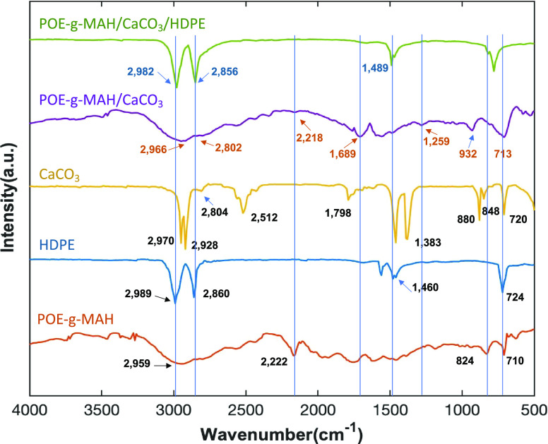
To confirm that the POE-g-MAH/CaCO3/HDPE polymer composite has been successfully prepared, the FTIR spectra of the different stages of POE-g-MAH/CaCO3/HDPE polymer composite were obtained, as shown in Figure 4. To prove that POE-g-MAH was grafted on CaCO3, pure HDPE used for polymer composite preparation, POE-g-MAH (both as a control group), and the POE-g-MAH/CaCO3 microcapsule was extracted with the ethanol solvent. Then, the residues were characterized by FTIR. According to the functional groups as confirmed by the literature,16−18 the POE-g-MAH/CaCO3 microcapsule exhibited the absorption peaks of POE-g-MAH at 2966, 2802, 2218, 1689, 1259, 932, and 713 cm–1 marked in brown,16 but its spectra might had been affected and still retained similar absorption peaks to CaCO3 at 2804, 1798, 848, and 720 cm–1.17 As for the spectra for the POE-g-MAH/CaCO3 microcapsule, there was some migration that happened compared with CaCO3, but after comparing it with the product after solvent extraction, it was not obvious to observe the mitigation of peaks among different composites. Also, this might be caused by the complex spatial structure in between POE-g-MAH and CaCO3.
Figure 4.
FTIR spectra of the compatibilizer component POE-g-MAH, pure HDPE, the CaCO3 microdroplet, the POE-g-MAH/CaCO3 microcapsule, and the POE-g-MAH/CaCO3/HDPE polymer composite.
After the POE-g-MAH/CaCO3/HDPE polymer composite was formed, the FTIR spectra only displayed most of the characteristic peaks of HDPE at 2982, 2856, and 1489 cm–1 as illustrated in dark blue.17,18 The peaks of individual CaCO3 or POE-g-MAH were merged and became smooth, which might indicate the coverage and distribution of HDPE and POE-g-MAH/CaCO3 microcapsules and the immobilization of CaCO3 in the polymer composite. Transmission electron microscopy (TEM) images for all the samples were also obtained for their interfacial characterizations. However, as the transparency for the samples was very low, the distribution of CaCO3 microdroplets within the composite and microcapsule could be barely seen in Figure 5a–c with different magnifications. The interface between the CaCO3 microdroplet and POE-g-MAH/CaCO3 microcapsule was marked, and the surrounding irregular structure attached with the microcapsule was believed to be the HDPE matrix. Such interfacial adhesion could also be concluded from the previous SEM characterization section.19,20
Figure 5.

TEM images of the POE-g-MAH/CaCO3/HDPE polymer composite at different magnifications: (a) structures of the CaCO3 microdroplet, (b) interface between POE-g-MAH and CaCO3 within the POE-g-MAH/CaCO3 microcapsule, and (c) interface within the polymer composites.
3.4. Processing Performance Analysis of the Newly Fabricated Recycled Pipe Materials
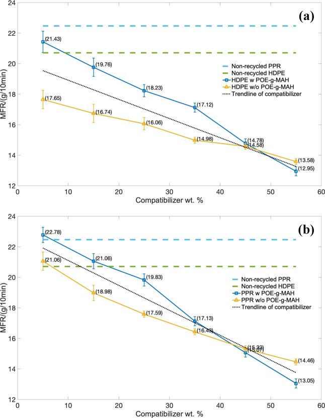
The processing rheology, which represented the processability of the melt flow rate (MFR), was performed under the same applied stress at 2.45 × 10⁵ Pa. The HDPE series piping material with the MFR over the mass percentage of the compatibilizer is indicated in Figure 6a, and the PPR-based series is indicated in Figure 6b.
Figure 6.
Melt flow rate (MFR) over the mass of the compatibilizer: (a) HDPE series and (b) PPR series.
For the HDPE piping series, the MFR of the composites decreased with the increment of two compatibilizers as demonstrated in the trend line. The same decreasing tendency also happened in the PPR piping series, which can be summarized as follows: the more the compatibilizer used, the smaller the melt flow rate becomes. The reason could be due to the large possibility of the CaCO3 filler particles gathering together in the composite blending system. AS most of the fluidity within the composite changed to aggregating state, the MFR reduced. However, with the help of the grafted POE-g-MAH, the decrement of the flowability and the MFR would become slower than the groups without POE-g-MAH., Even at a lower weight percentage of compatibilizer, the MFR performance would be better than those of pure HDPE and PPR. It should be caused by the core–shell structure composed of individual CaCO3 and POE-g-MAH, and it could increase the dispersion and the faster thermal response during the process.
Also, the values of shear rate, viscosity, and flow rate with the samples in the capillary rheometer test were also obtained, as shown in Tables 2 and 3. Although the MFR and processability might be continuously decreasing for both HDPE and PPR with and without POE-g-MAH, still with little amount of POE-g-MAH, the processing performance became higher than those of the non-recycled materials compared with the imaginary lines. To conclude, the more that the mass of the compatibilizer was increased, the worse the flowability and processability we would end up with.
Table 2. Shear Rate, Viscosity, and Flow Rate of the HDPE Series.
| formulation code name | flow rate × 10–2/(cm3/s) | viscosity × 102/(Pa·s) | shear rate × 102 / s–1 |
|---|---|---|---|
| non-recycled HDPE | 3.49 ± 0.22 | 6.97 ± 0.15 | 3.53 ± 0.47 |
| 5% w POE-g-MAH | 3.23 ± 0.12 | 7.26 ± 0.73 | 3.28 ± 0.13 |
| 15% w POE-g-MAH | 2.85 ± 0.51 | 8.14 ± 0.19 | 2.93 ± 0.81 |
| 25% w POE-g-MAH | 2.67 ± 0.09 | 8.99 ± 0.14 | 2.72 ± 0.17 |
| 35% w POE-g-MAH | 2.49 ± 0.27 | 9.63 ± 0.99 | 2.54 ± 0.62 |
| 45% w POE-g-MAH | 2.43 ± 0.15 | 9.91 ± 0.12 | 2.47 ± 0.59 |
| 55% w POE-g-MAH | 2.26 ± 0.33 | 10.64 ± 0.58 | 2.31 ± 0.28 |
| 5% w/o POE-g-MAH | 3.04 ± 0.13 | 7.52 ± 0.34 | 3.15 ± 0.29 |
| 15% w/o POE-g-MAH | 2.79 ± 0.27 | 8.24 ± 0.22 | 2.91 ± 0.28 |
| 25% w/o POE-g-MAH | 2.58 ± 0.11 | 8.74 ± 0.55 | 2.74 ± 0.19 |
| 35% w/o POE-g-MAH | 2.40 ± 0.72 | 9.43 ± 0.77 | 2.53 ± 0.82 |
| 45% w/o POE-g-MAH | 2.29 ± 0.48 | 9.87 ± 0.92 | 2.42 ± 0.29 |
| 55% w/o POE-g-MAH | 2.14 ± 0.54 | 9.98 ± 0.79 | 2.28 ± 0.45 |
Table 3. Shear Rate, Viscosity, and Flow Rate of the PPR Series.
| formulation code name | flow rate × 10–2 / (cm3/s) | viscosity × 102 / (Pa·s) | shear rate × 102 / s–1 |
|---|---|---|---|
| non-recycled PPR | 3.74 ± 0.27 | 6.426 ± 0.29 | 3.82 ± 1.26 |
| 5% w POE-g-MAH | 3.57 ± 0.22 | 6.795 ± 0.84 | 3.73 ± 0.57 |
| 15% w POE-g-MAH | 3.48 ± 0.23 | 7.231 ± 1.22 | 3.52 ± 0.63 |
| 25% w POE-g-MAH | 3.21 ± 1.17 | 7.945 ± 1.27 | 2.98 ± 0.91 |
| 35% w POE-g-MAH | 2.98 ± 0.36 | 8.646 ± 0.93 | 2.94 ± 0.52 |
| 45% w POE-g-MAH | 2.67 ± 0.29 | 9.735 ± 0.56 | 2.64 ± 0.43 |
| 55% w POE-g-MAH | 2.43 ± 0.43 | 10.523 ± 0.43 | 2.47 ± 0.27 |
| 5% w/o POE-g-MAH | 3.58 ± 1.19 | 6.673 ± 0.53 | 3.71 ± 0.41 |
| 15% w/o POE-g-MAH | 3.47 ± 0.18 | 6.842 ± 0.41 | 3.50 ± 1.23 |
| 25% w/o POE-g-MAH | 3.31 ± 0.27 | 7.281 ± 0.98 | 3.37 ± 0.51 |
| 35% w/o POE-g-MAH | 2.85 ± 0.46 | 8.430 ± 1.15 | 2.91 ± 0.48 |
| 45% w/o POE-g-MAH | 2.52 ± 1.12 | 9.582 ± 0.42 | 2.59 ± 0.37 |
| 55% w/o POE-g-MAH | 2.37 ± 0.31 | 9.801 ± 1.19 | 2.32 ± 1.02 |
3.5. Mechanical Properties of the Newly Fabricated Recycled Pipe Materials
3.5.1. Tensile Strength
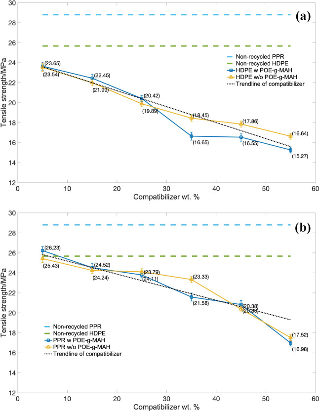
The results of tensile strength (TS) of the HDPE series piping material with the strain over the stress are indicated in Figure 7a, and the PPR-based series is indicated in Figure 7b. As indicated in the figure, both the tensile strengths of the HDPE and PPR series decreased with the increment of the compatibilizer. Also, with the greater amount of CaCO3 particles, worse compatibility was demonstrated between the original polyolefins and these compatibilizers as well as the poorer dispersibility of particles in the base particle. As the samples were subjected to tensile force, the CaCO3 particles easily fell off the interface, gaps would become larger, and the tensile strength decreased. It was also indicated that the use of the graft POE-g-MAH compatibilizer in both polyolefin series led to similar tensile strength than without the use of POE-g-MAH.
Figure 7.
Tensile strength (TS) over the mass of the compatibilizer: (a) HDPE series and (b) PPR series.
3.5.2. Flexural Properties
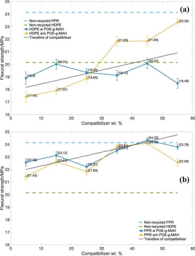
The results of flexural strength of the HDPE series piping material over the stress are indicated in Figure 8a, and the PPR based-series is indicated in Figure 8b. The same values of blue and green imaginary lines are also provided in Figure 8a,b, which could be referred to from there to see the variation between the POE-g-MAH compatibilizer and the flexural strength. For both HDPE and PPR series, the introduction of POE-g-MAH into the two series composites would increase the flexural strength from the demonstration of the trend line. This was due to the addition of the composite particles and its core–shell structure blocking the movement of the molecular chain, and the flexural strength of the composites could be enhanced. Compared with the PPR series, there was a remarkable improvement for the HDPE series without POE-g-MAH with the increment as high as 5.93 MPa, from 17.42 to 23.35 MPa, which indicated the great enhancement of these CaCO3-based compatibilizers in the recycled high-density polythene. In order to exhibit the significance of POE-g-MAH within the PPR series, the region between blue and green imaginary lines was zoomed up. For the PPR series, although there was a slight increase from 22.6 MPa with 5% and 23.8 MPa with 55%, still these small trends would matter in the selection of HDPE-PPR-POE-g-MAH/CaCO3-blended system, which would be further discussed in following section.
Figure 8.
Flexural strength (TS) over mass of compatibilizer: (a) HDPE series and (b) PPR series.
Furthermore, the usage of the POE-g-MAH/CaCO3/HDPE polymer composite indicated the significant increase compared with the ones without the polymer composite in both HDPE and PPR series. The composite did not have much of an affect for the flexural strength at all mass ratios. Moreover, a slight decrement would even occur as the mass ratio gradually increased from 15 to 35%. Also, the decreasing intervals of the HDPE series were higher than those of the PPR series reaching 1.5 MPa. As shown in Figure 8a,b, as the weight percentage of the POE-g-MAH/CaCO3/HDPE polymer composite went to 35 and 25%, there was minimum flexural strength for the HDPE and PPR series, respectively. This is because the POE-g-MAH/CaCO3/HDPE polymer composite was well dispersed in the recycled HDPE and PPR-blended system, which was able to enhance the toughness of the composites rather than the flexural strength.
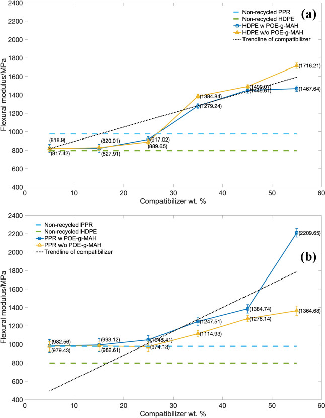
The results of flexural modulus (FM) of the DPE series piping material over the stress are indicated in Figure 9a, and the PPR series is indicated in Figure 9b. For the trend lines of both HDPE and PPR series, the increment of these two compatibilizers would significantly increase the flexural modulus. This was due to the modulus of the CaCO3 particles would be ten to hundred times of the pure polyolefins. In addition, the increment in the HDPE series was higher than those corresponded PPR groups, which indicated the better dispersion of CaCO3-based compatibilizers in HDPE-blended systems.
Figure 9.
Flexural modulus (FM) over the mass of the compatibilizer: (a) HDPE series and (b) PPR series.
Moreover, the flexural modulus of the HDPE series without the POE-g-MAH elastomer was superior to those of the groups with the POE-g-MAH elastomer. This was because of the POE-g-MAH elastomer and its microcapsule structure would enhance the toughness rather than flexural modulus as pre-discussed in flexural strength. While in the PPR series, the increment for the group with POE-g-MAH/CaCO3 microcapsules indicated better flexural modulus performance, and it was definitely caused by the better dispersion without the help of POE-g-MAH. Also, the whole series of PPR did not increase as much from 5 to 55% of mass as those HDPE series.
In general, with the consideration for both flexural strength and flexural modulus, the addition of compatibilizers had an enhancing effect on the bending performance for both HDPE and PPR series. For the HDPE series, though the introduction of the POE-g-MAH elastomer would slightly increase the flexural performance, it would obtain a balance between high flexural properties and high toughness. While for the PPR series, the POE-g-MAH elastomer would significantly increase the flexural performance only, it would only donate the effect of CaCO3 particles in the recycled PPR.
3.5.3. Impact Performance
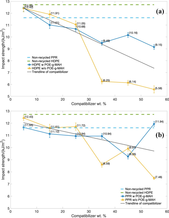
The results of impact strength (IS) of the HDPE series piping material over the weight percentage of the compatibilizer are indicated in Figure 10a, and the PPR-based series is indicated in Figure 10b. As for both of these two series, the introduction of CaCO3 particles could substantially increase the notched impact strength and the rigidity of the composites, which was presented in the trend lines for all these groups. Conversely, the toughness for the composites would be reduced. Generally, the more particles there are inside these two blended systems, the poorer the toughness and the worse the impact properties the composite would be; and the PPR series indicated better impact performance than the corresponding HDPE series.
Figure 10.
Impact strength over the mass of the compatibilizer: (a) HDPE series and (b) PPR series.
The results also indicated that the use of the POE-g-MAH compatibilizer in both polyolefin series had higher impact strength than the one without the POE-g-MAH compatibilizer, especially at its high mass regions. Although the weight percentage of POE-g-MAH compatibilizer continuously rose to 45%, there was still a certain impact strength increased mutation more in those HDPE series than PPR. The same tendency happened for the PPR series at the mass of 55%, which was even higher than the non-recycled PPR. All these results demonstrated that the impact properties, owing to the POE-g-MAH-grafted compatibilizer, would increase the impact strength and might even obtain a balance with the toughness as well. In sum, the introduction of any compatibilizers into the recycled HDPE and PPR blended system would slightly decrease the impact strength, wherein the formulation groups with the POE-g-MAH compatibilizer would drop less, because of the toughening effect from the POE-g-MAH.
3.6. Formulation Analysis of the Tertiary HDPE/PPR and POE-g-MAH/CaCO3/HDPE-Blended System
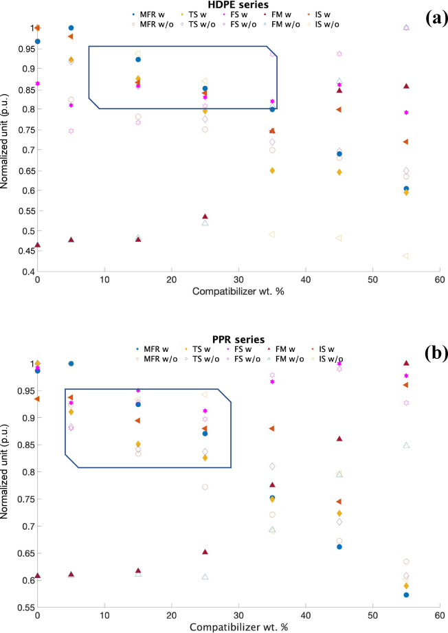
For visual representation of the how the mass of this polymer composite in Figure 11 would affect individual factors, including melt flow rate (MFR), tensile strength (TS), flexural strength (FS), flexural modulus (FM), and impact strength (IS), and even for the overall performance, a formulation analysis graph using a normalized unit (p.u.) was obtained. The design of such a figure was to deploy all the experimental results obtained above into one figure for each series (PPR or HDPE) into a normalized unit. Hence, the closer the performance was to 1, the better the performance it referred to. Also, this method was commonly used in statistics and might help in the selection for the overall best formulation. Also, the formulation groups with (w) and without (w/o) polymer composites are also included in the figures. It was not difficult to find that (i) as the overall normalized unit of PPR series was higher: the PPR series recycled materials had its lowest normalized score at 0.57, indicating the slightly better performance of the recycled HDPE series with the lowest score at 0.45; (ii) the processing performance and mechanical properties was very sensitive to the mass of polymer composites. Considering the variations of these five factors and even the opposite tendency among these factors, a region of normalized unit within the range of 0.80–0.95 and concentrated distribution was encircled in Figure 11a,b as well. Moreover, this shaded area should be where the exact optimal formulation group falls in; (iii) due to the different component of the recycled materials, what these results might offer was just the range of the weight percentage of the polymer composite; (iv) for the recycled HDPE series, the optimized formula region of the polymer–composite mass would be in the range between 8 and 35%, while for the PPR series, the optimized region of polymer–composite mass would be at 5 to 25%. In addition, these results might help in the formulation design of HDPE-PPR-POE-g-MAH/CaCO3 blended systems in the following section.
Figure 11.
Formulation analysis by using the normalized unit over the mass of the compatibilizer: (a) HDPE series and (b) PPR series.
3.7. Performance Analysis of the HDPE-PPR-POE-g-MAH/CaCO3/HDPE Blended System
According to the results and discussion of mechanical performance, recycled high-density polypropylene (HDPE) was characterized with good mechanical properties and enhanced rigidity. At the same time, due to the high tensile strength of recycled random copolymer polypropylene (PPR) and good bending resistance, these results did provide important reference and possibility for the fabrication of a POE-g-MAH/CaCO3/HDPE blended system. Moreover, mixing with a twin screw extruder would contribute to higher impact strength as compared to direct injection.28
Trials of the HDPE-PPR-POE-g-MAH/CaCO3/HDPE blended system were also performed. Several optimized formulations were selected and their tensile, flexural, and impact properties were studied, indicated in Tables 4 and 5. Table 4 shows that the mechanical properties of the recycled materials would increase and then decrease with the mass increment of the POE-g-MAH/CaCO3/HDPE polymer composite. The best mechanical performance formulation groups would be the ones with a mass ratio of 3:2:1 for HDPE:PPR:POE-g-MAH/CaCO3/HDPE, which included a higher HDPE mass (16.7%) than PPR or POE-g-MAH/CaCO3/HDPE. This was because the structure of polypropylene is easier to be oxidized and degraded under ultraviolet light and heat due to PPR having a methyl side chain before being recycled.
Table 4. Mechanical Properties of the Recycled HDPE-PPR-POE-g-MAH/CaCO3 Blended System.
| HDPE:PPR:POE-g-MAH/CaCO3/HDPE | maximum bending stress (MPa) | flexural modulus (MPa) | impact strength (J) | maximum tensile stress (MPa) |
|---|---|---|---|---|
| 1:1:1 | 19.05 ± 4.11 | 553.97 ± 10.82 | 0.60 ± 0.03 | 16.08 ± 4.52 |
| 2:3:1 | 24.42 ± 3.72 | 1033.14 ± 20.72 | 0.40 ± 0.02 | 16.85 ± 5.13 |
| 3:3:2 | 22.61 ± 4.51 | 1342.38 ± 22.13 | 0.34 ± 0.09 | 18.14 ± 3.78 |
| 3:2:1 | 21.78 ± 4.09 | 1256.43 ± 21.42 | 0.38 ± 0.07 | 17.89 ± 4.85 |
| 2:2:1 | 21.55 ± 4.69 | 978.96 ± 19.51 | 0.36 ± 0.09 | 24.44 ± 6.95 |
Table 5. Mechanical Properties of Non-recycled HDPE-PPR-POE-g-MAH/CaCO3 Blended System.
| HDPE:PPR:POE-g-MAH/CaCO3/HDPE | maximum bending stress (MPa) | flexural modulus (MPa) | impact strength (J) | maximum tensile stress (MPa) |
|---|---|---|---|---|
| 1:1:1 | 21.90 ± 3.35 | 1010.44 ± 20.07 | 0.38 ± 0.88 | 15.31 ± 3.90 |
| 2:3:1 | 22.91 ± 4.14 | 1011.31 ± 19.93 | 0.38 ± 0.41 | 17.55 ± 5.10 |
| 3:3:2 | 20.48 ± 3.72 | 1258.31 ± 22.01 | 0.46 ± 0.37 | 12.24 ± 3.40 |
| 3:2:1 | 20.42 ± 3.93 | 815.69 ± 18.10 | 0.37 ± 0.21 | 19.95 ± 4.60 |
| 2:2:1 | 20.79 ± 3.82 | 902.61 ± 20.12 | 0.37 ± 0.16 | 22.35 ± 4.09 |
It could also be observed that the non-recycled material for such blended systems would have the best mechanical performance for the formulation group with a HDPE:PPR:POE-g-MAH/CaCO3/HDPE mass ratio of 2:3:1, which contained less HDPE than the recycled groups. Furthermore, the gap between recycled and non-recycled materials, in Table 5, was further reduced, and such a blended system did prove the mechanical capacity of recycled materials might be better than that of the non-recycled ones. This trial study could also lead to significant commercial development.
4. Conclusions
This experiment used a modified POE-g-MAH/CaCO3/HDPE polymer composite to enhance the recycled high-density polyethylene and polypropylene for better preparation of a double-wall corrugated pipe. The fabrication mechanism of POE-g-MAH/CaCO3 microcapsules and the processing performance and mechanical properties for different piping formulations were investigated.
The POE-g-MAH/CaCO3/HDPE polymer composite was able to reinforce the recycled HDPE and PPR by obtaining significant improvement in processability, flexural performance, impact force, and even durability. The usage of POE-g-MAH could contribute to the impressive balance between high rigidity and high toughness. However, the mass of the POE-g-MAH/CaCO3/HDPE polymer composite should not be too high, and the proper mass range should be neither higher than 35% nor lower than 8%. Furthermore, trials and studies of the potential capacity and mechanical property of the HDPE-PPR-POE-g-MAH/CaCO3/HDPE blended system were also performed. Results showed that the gaps between recycled and non-recycled materials would be further reduced with the help of the POE-g-MAH/CaCO3 microcapsules, and such a blended system promises great commercial value in the industry.
Acknowledgments
This research was funded by the MOE Academic Research Fund (AcRF) Tier 1 Project “Nano-structured Titania with tunable hydrophilic/hydrophobic behavior and photocatalytic function for marine structure application,” Grant Call (Call 1/2018) _MSE (EP Code EP5P, Project ID 122018-T1-001-077), Ministry of Education (MOE), Singapore, the National Natural Science Foundation of China (Grant number 51704258), and the Natural Science Foundation of Hunan Province, China (Grant No. 2019JJ50587).
The authors declare no competing financial interest.
References
- Long N.; Hsuan G. Y.; Spatari S. Life Cycle Economic and Environmental Implications of Pristine High-Density Polyethylene and Alternative Materials in Drainage Pipe Applications. J. Polym. Environ. 2017, 25, 925–947. 10.1007/s10924-016-0843-y. [DOI] [Google Scholar]
- Saur K.; Fava J. A.; Spatari S. Life cycle engineering case study: automobile fender designs. Environ. Prog. 2000, 19, 72–82. 10.1002/ep.670190205. [DOI] [Google Scholar]
- Lloyd S. M.; Lave L. B. Life cycle economic and environmental implications of using nanocomposites in automobiles. Environ. Sci. Technol. 2003, 37, 3458–3466. 10.1021/es026023q. [DOI] [PubMed] [Google Scholar]
- Recio J. B.; Baldasano J. M.; Guerro P. J.; Ageitos M. G.; Narváez R. P.. Estimate of energy consumption and CO2 associated with the Preoduction. Use and Final Disposal of PVC, HDPE, PP. Ductile Iron and Concrete Pipes, Barcelona (2005).
- Juliane P.-R.; Ferreguetti Á. C.; Bergallo H. G.; Rocha C. F. D. Use of Polyvinyl Chloride Pipes (PVC) as Potential Artificial Shelters for Amphibians in a Coastal Plain Forest of Southeastern Brazil. J. Coastal. Conserv. 2017, 21, 327–331. 10.1007/s11852-016-0480-6. [DOI] [Google Scholar]
- Majid F.; Elghorba M.. Continuum Damage Modeling through Theoretical and Experimental Pressure Limit Formulas. Frat. ed Integrita Strutt. , 43 (), 79–89, 10.3221/IGF-ESIS.43.05. [DOI] [Google Scholar]
- Kim J.-S.; Yoo J.-H.; Oh J.-Y. A Study on Residual Stress Mitigation of the HDPE Pipe for Various Annealing Conditions. J. Mech. Sci. Technol. 2015, 29, 1065–1073. 10.1007/s12206-015-0218-7. [DOI] [Google Scholar]
- Latifa A.; Azzouz S.; Chaoui K.. Reliability Index of HDPE Pipe Based on Fracture Toughness. Mechanika , 23 (), 820–825. [Google Scholar]
- Deng C.; Jin B.; Zhao Z.; Shen K.; Zhang J. The Influence of Hoop Shear Field on the Structure and Performances of Glass Fiber Reinforced Three-layer Polypropylene Random Copolymer Pipe. J. Appl. Polym. Sci. 2019, 136, 46985. 10.1002/app.46985. [DOI] [Google Scholar]
- Chen J.; Wang G.; Zeng X.; Zhao H.; Cao D.; Yun J.; Tan C. K. Toughening of Polypropylene-Ethylene Copolymer with Nanosized CaCO3 and Styrene-butadiene-styrene. J. Appl. Polym. Sci. 2004, 94, 796–802. 10.1002/app.20925. [DOI] [Google Scholar]
- Ge Q.; Wu T.; Ding L.; Yang F.; Xiang M. Effect of Annealing on Microstructure and Mechanical Properties of Polypropylene Random Copolymer. Soft Mater. 2019, 17, 1–13. 10.1080/1539445X.2018.1528456. [DOI] [Google Scholar]
- Hao W.; Li W.; Yang W.; Shen L. Effect of silicon nitride nanoparticles on crystallization behavior of PP. Polym. Testing 2011, 30, 527–533. 10.1016/j.polymertesting.2011.04.003. [DOI] [Google Scholar]
- Hussain F.; Hojjati M.; Okamoto M.; Gorga R. E. Review article: polymer matrix nanocomposites, processing manufacturing and application an overview. J. Compos. Mater. 2006, 40, 1511–1575. 10.1177/0021998306067321. [DOI] [Google Scholar]
- www.astm.org
- www.astm.org
- Devi S. H. K.; Shashidhara G. M.; Ghosh A. K. Characterization of HDPE/MMT-based nanocomposites. Compos. Interfaces 2010, 17, 217–222. 10.1163/092764410X490617. [DOI] [Google Scholar]
- Deepthi M. V.; Sharma M.; Sailaja R. R. N.; Anantha P.; Sampathkumaran P.; Seetharamu S. Mechanical and thermal characteristics of high density polyethylene-flyash cenospheres composites. J. Mater. Des. 2010, 31, 2051–2060. 10.1016/j.matdes.2009.10.014. [DOI] [Google Scholar]
- Sarker M.; Rashid M. M.; Molla M. Abundant High-Density Polyethylene (HDPE-2) turns into fuel by using of HZSM-5 catalyst. J. Fundam. Renew. Energy Appl. 2013, 1, 1–12. 10.4303/jfrea/R11020. [DOI] [Google Scholar]
- Ray S. S.; Okamoto M. Polymer/layered silicate nanocomposites a review from preparation to processing. Prog. Polym. Sci. 2003, 28, 1539–1641. 10.1016/j.progpolymsci.2003.08.002. [DOI] [Google Scholar]
- Wang X.; Mi J.; Wang J.; Zhou H.; Wang X. Multiple actions of poly(ethylene octene) grafted with glycidyl methacrylate on the performance of poly(lactic acid). RSC Adv. 2018, 8, 34418–34427. 10.1039/C8RA07510G. [DOI] [PMC free article] [PubMed] [Google Scholar]
- Zhon W.; Wang C.; Ai T.; Wu K.; Zhao F.; Gu H. A novel fibre reinforced polyethylene composite with added silicon nitride particles for enhanced thermal conductivity. Composites, Part A 2009, 40, 830–836. 10.1016/j.compositesa.2009.04.005. [DOI] [Google Scholar]
- Shi G.; Zhang M. Q.; Rong M. Z.; Wetzel B.; Friedrich K. Friction and wear of low nanometer Si3N4 filler epoxy composites. Wear 2003, 254, 784–796. 10.1016/S0043-1648(03)00190-X. [DOI] [Google Scholar]
- Hussain F.; Hojjati M.; Okamoto M.; Georga R. E. Polymer-matrix nanocomposites, processing manufacturing and application an overview. J. Compos. Mater. 2006, 40, 1511–1575. 10.1177/0021998306067321. [DOI] [Google Scholar]
- Croitoru C.; Alexandru P.; Roata I. C.; Stanciu E.-M. Obtaining and Characterization of Polyolefin-Filled Calcium Carbonate Composites Modified with Stearic Acid. IOP Conf. Ser. Mater. Sci. Eng. 2017, 209, 012041 10.1088/1757-899X/209/1/012041. [DOI] [Google Scholar]
- Deepthi M. V.; Sailaja R. R. N.; Sampathkumaran P.; Vynatheya S.; Seetharamu S.. Study of tribological properties of cenospheres filled HDPE composites. Mater. Sci. Indian J. , 6 (), 8–12. [Google Scholar]
- Zhang M. Q.; Rong M. Z.; Zhang H. B.; Friedrich K. Mechanical Properties of Low Nano-silica Filled High Density Polyethylene Composites. Polym. Eng. Sci. 2003, 43, 490–500. 10.1002/pen.10040. [DOI] [Google Scholar]
- Xu G. C.; Wang J.; Ji X. L.; Xiong J. X.; Li F. Effect of nanosilicon nitride on the mechanical electric properties of polypropylene nanocomposite. J. Compos. Mater. 2007, 41, 2213–2223. 10.1177/0021998307074185. [DOI] [Google Scholar]
- Deka B. K.; Maji T. K. Effect of nanoclay and Zn O on the physical and chemical properties of wood polymer nanocomposite. J. Appl. Polym. Sci. 2012, 124, 2919–2929. 10.1002/app.35314. [DOI] [Google Scholar]


