Abstract
Background:
Notwithstanding the widespread implementation of flow diverters (FDs) in the treatment of intracranial aneurysms, the exact mechanism of action of these devices remains elusive. We aimed to advance the understanding of cellular responses to FD implantation using a 3D tissue-engineered in vitro aneurysm model.
Methods:
Aneurysm-like blood vessel mimics (aBVMs) were constructed by electrospinning polycaprolactone nanofibers onto desired aneurysm-like geometries. aBVMs were sodded with human aortic smooth muscle cells (SMCs) followed by human aortic endothelial cells (ECs). FDs were then deployed in the parent vessel of aBVMs covering the aneurysm neck and were cultivated for 7, 14, or 28 days (n=3 for each time point). The EC and SMC coverage in the neck was measured semi-quantitatively.
Results:
At day 7, the device segment in contact with the parent vessel was partially endothelialized. Also, the majority of device struts, but not pores, at the parent vessel and neck interface were partially covered with ECs and SMCs, while device struts in the middle of the neck lacked cell coverage. At 14 days, histology verified a neointimal-like lining had formed, partially covering both the struts and pores in the center of the neck. At 28 days, the majority of the neck was covered with a translucent neointimal-like layer. A higher degree of cellular coverage was seen on the struts and pores at the neck at 28 days compared to both 7 and 14 days.
Conclusion:
aBVMs can be a valuable alternative tool for evaluating the healing mechanisms of endovascular aneurysm devices.
Introduction
Flow diverters (FDs) have become a desirable treatment choice for intracranial, saccular aneurysms, and their high occlusion rates and acceptable safety profiles have been validated in many clinical trials1-3. In some centers, up to 1/3 of aneurysms are treated with FDs4. Despite the widespread use of these devices, their mode of action in achieving endothelialization and complete aneurysm occlusion remains elusive. Some previous pre-clinical studies have shown that endothelialization of aneurysms following FD implantation is derived from the parent artery5, while others have postulated circulating progenitor cell-mediated endothelialization6.
In this current study we utilize an aneurysm-like blood vessel mimic (aBVM) to better understand the interaction between vasculature and implanted FD devices. These aBVMs are composed of tubular polymeric scaffolds, seeded with human endothelial and smooth muscle cells, and cultivated in individual bioreactor systems under steady flow conditions 7. They have been well established for evaluating endothelialization of coronary stents and for the development of intravascular imaging modalities8-10, and proof of concept work has demonstrated their utility for evaluating endovascular aneurysm devices7, 11. This study aimed to advance the understanding of cellular responses to FD implantation using a three-dimensional tissue-engineered in vitro aneurysm model.
Materials and Methods
An overview of the experimental approches are provided in the supplementary video.
Cell Culture
The human aortic endothelial cells (ECs) and human aortic smooth muscle cells (SMCs) were purchased from the American Type Culture Collection (ATCC, Manassas, USA). The ECs were cultured in Endothelial Cell Growth medium (Vascular Cell Basal Medium supplemented with Microvascular Endothelial Cell Growth Kit – VEGF, ATCC® PCS-100-041, Manassas, USA). The SMCs were cultured in Vascular Cell Basal Medium supplemented with Vascular Smooth Muscle Cell Growth Kit (ATCC® PCS-100-042, Manassas, USA). All the cells were maintained at 37°C, 95% humidity, and 5% CO2 with medium changed every 48-72 hours.
Aneurysm-like scaffold creation
Polycaprolactone (PCL) (Mn80,000, Sigma-Aldrich) solution (15% wt./v) was prepared in a mixture of glacial acetic acid and acetone (7:3) overnight in a water bath at 70°C. The PCL solution was then placed into a 12 ml syringe and dispensed at a flow rate of 0.02 ml/min through the 20-gauge blunt-tip needle. Aneurysm geometries were created using molded aluminum foil wrapped around a straight stainless-steel mandrel. The mandrel was positioned 10 cm from the needle tip and was rotated at 250 RPM. The voltage between the needle tip and the rotating mandrel was set to 13 kV. Electrospinning was performed for 2.9-3.6 hours until a saccular aneurysm-like scaffold was formed. The resulting tubular aneurysm-like scaffold (the aBVM) was then removed from the mandrel.
Scaffold conditioning and cell seeding
The aBVMs were prepared as described earlier.11 The scaffolds were sterilized with 70% ethanol and pre-conditioned with cell culture media prior to seeding the cells. Bioreactor chambers were assembled as described previously, using a flow rate-controlled peristaltic pump (ISM932, ISMATEC), with the aBVM scaffolds secured with sterile suture loops. The SMCs were seeded inside the scaffold at a density of 1 × 10⁶ cells/cm2, distributing the cells evenly by rotating the chambers 180° along the long axis every 30 min while incubating under static conditions. The ECs were seeded the following day, following the same procedure. Mixed cell culture media (1:3 ratio of SMC media to EC media) was placed in the reservoir tube to maintain the cells. The aBVMs were cultured for 24 hours at 1.00 ml/min flow rate of cell culture media.
FD deployment
Prior to FD implantation, the bioreactor chamber containing aBVMs were disconnected from tubing connected to the peristaltic pump and transferred from the incubator to the fluoroscopy room under aseptic conditions. The FDs (Pipeline Flex Embolization Device, Medtronic Inc., Irvine, California, USA) were aseptically deployed into each aBVM following standard methods. Briefly, a microcatheter (Marksman, Medtronic Inc., Irvine, California, USA) was placed into the “distal” end of the aBVMs parent vessel with guidance of a micro guidewire (Transcend; Boston Scientific, Marlborough, Massachusetts, USA). Iodinated contrast mixed with saline (~1 cc; 1:1 ratio) was injected to create a roadmap. The FD was advanced beyond the distal end of the microcatheter and deployed slowly across the aneurysm neck under fluoroscopy. Digital Subtraciton Angiography (DSA) was performed through the microcatheter to confirm the device location before the microcatheter was removed. The residual contrast was flushed out by the injection of saline through aBVMs containing implanted FDs. Then the bioreactor chamber with aBVMs+FDs were returned to the incubator, attached to the tubing connected to the peristaltic pump, and cultivated for a pre-specified time. The pump rate was increased form 1.00 ml/min to 5.00 ml/min after 24 hours.
Whole-Mount en Face Immunostaining
The FD-bearing aBVM samples were processed for whole-mount staining as described previously5, 12. Briefly, 7, 14 and 28 days after device implantation, the FD–implanted aBVMs were harvested. Each was washed with 1x Tris-Buffered Saline (TBS) and fixed with 10% neutral buffer formalin (NBF) for at least 24 hours. The flow diverter bearing aBVMs were longitudinally cut using a scissor with extra fine blade (Extra Fine Bonn, No.14084-08, F.S.T) at the opposite to the aneurysm neck to expose the lumen. Tissue coverage on the device struts that crossed over the neck orifice and sat within the parent vessel was grossly evaluated. Immunostaining was performed using antibodies against CD31 (Dako, Carpentaria, California) and smooth muscle actin (SMA) (Dako, Carpentaria, California). Specific binding was visualized using fluorescently-conjugated secondary antibodies (Cy3- or Alexa Flour 488 conjugated donkey anti-mouse IgG; Jackson Immuno Research, West Groove, PA), with DAPI (Invitrogen) to stain the nucleus. Stained specimens were imaged on a confocal microscope (Olympus BX61, Japan). Cell/tissue coverage was evaluated and scored in the inner half as well as outer half of the neck by a trained pathologist using a 0-4 semi-quantitative scale system: 0) No cells/tissue visible; 1) cells present on device struts, but not yet confluent; no cells/tissue within device pores; 2) confluent cell growth on device struts with no gap between cells; no cells/tissue within device pores; 3) confluent cell growth on device struts with no gap between cells; some cell/tissue growth within pores; 4) struts and pores completely covered with cells/tissue.
Results
Geometries of aBVMs
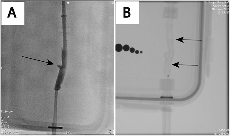
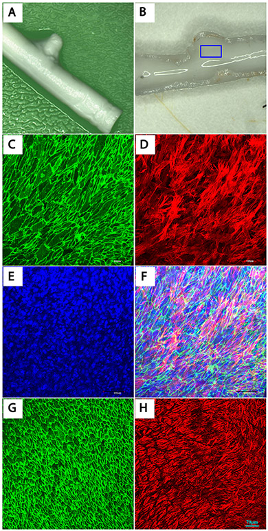
An untreated aBVM for each batch was longitudinally cut open to expose the luminal side and stained with CD31, SMA and DAPI to confirm the cellular confluency of the cell coverage in the parent vessel before proceeding to FD implantation (Figure 1). The FDs were implanted in all aBVMs (n=9) without incident. The mean diameter of aBVM parent vessels was 4.6 mm. The mean aneurysm neck diameter, and height were 5.9 mm, and 3.2 mm, respectively. Immediate post-device placement DSA visualized device coverage over the neck (Figure 2).
Figure 1.
Confirmation of cellular confluency in aBVM prior to device implantation. (A) Gross macrophotograph image of an aBVM scaffold showing saccular aneurysm like a pouch (arrow). (B) Gross macrophotograph image of the lumen of an aBVM before FD implantation. (C–E) Confocal wholemount images taken from the “aneurysm/parent artery” region (rectangular area in B) showing confluent CD31 positive endothelial cells (C, green) and aSMA positive smooth muscle cells (D, red), and DAPI nuclear counter stain (E, blue) (confocal microscope, water lens x20). F shows panels C–E merged, confirming the confluent endothelial and smooth muscle cell layer in the aBVM lumen before device implantation. (G and H) Confocal wholemount images of a rabbit artery (positive control) showing CD31 positive endothelial cells (G, green) and aSMA positive smooth muscle cells (H, red). aBVM, aneurysm-like blood vessel mimic; aSMA, α-smooth muscle actin; FD, flow diverter.
Figure 2.

Angiographic images of aBVM. (A) DSA imaging showing aneurysm cavity (arrow) prior to device implantation. (B) Unsubtracted DSA showing device covering the aneurysm neck (arrows represent both ends of the device). aBVM, aneurysm-like blood vessel mimic; DSA, digital subtraction angiography.
Morphologic findings
Cell/tissue coverage scoring results are presented in Table 1. At 7 days, 2 of 3 samples had the device completely covering the neck; the remaining one sample showed the majority of the device crossed over the neck orifice. The device within the parent vessel was partially endothelialized. Most of the device struts covering the center of the aneurysm neck were devoid of cells. Patchy interrupted tissue islands were seen on device struts and within a few of the device pores over the peripheral neck near the parent vessel. Confocal microscopy revealed these tissue islands were composed of endothelial and smooth muscle cells (CD31+/SMA+). One sample showed scattered cells on device struts at both, over the neck or within the parent vessel; these cells were also positive for CD31 and SMA. The individual and mean score for this time point is listed in Table 1.
Table 1.
Whole mount stain of neck tissue/cells semi quantitative score
| Follow Up (day) |
Sample # | outer ½ region of the neck |
center ½ region of the neck |
|---|---|---|---|
| 7 day | 1 | 0.5 | 0.5 |
| 7 day | 2 | 3 | 0.5 |
| 7 day | 3 | 2 | 0.5 |
| Mean±SD | 1.83±1.26 | 0.5±0 | |
| 14 day | 1 | 3 | 1 |
| 14 day | 2 | 3 | 1 |
| 14 day | 3 | 3 | 1 |
| Mean±SD | 3±0 | 1±0 | |
| 28 day | 1 | 3 | 1.5 |
| 28 day | 2 | 4 | 3 |
| 28 day | 3 | NA | NA |
| Mean±SD | 3.5±0.7 | 2.25±1.06 |
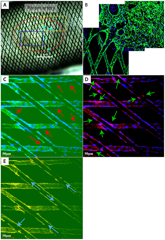
At 14 days, similar to 7 days, 2 of 3 samples had the device completely covering the neck, the FD in one sample did not fully bridge the entire neck. The device within the parent vessel was partially endothelialized. The device struts in the outer half region of the neck were partially covered with translucent tissue (Figure 2), while the device struts in the inner half of the neck were grossly bare but were actually wrapped with one single layer of non-confluent cells (Figure 2). The cells that either covered the struts or filled in the pores between struts were positive for both CD31 and SMA stains (Figure 2), they also continued up to the cells in the parent vessels (Figure 2) suggesting that the cells from the parent vessel migrated to the neck area of non-confluent CD31, or SMA positive cells (Figure 3).
Figure 3.
Figure 3 FD implanted aBVM harvested at 14 days. (A) Gross image shows the “aneurysm” neck covered with FD (red circle). Several islands of thin translucent tissue are attached to the struts or filled the pores between struts at the periphery of neck and parent artery interface (arrows). The blue rectangular area demonstrates grossly bare struts at the neck. The whole-mount (B) taken from the yellow rectangular area in panel A shows CD31 positive endothelial cells (green) that are confluent and fully cover the struts in the parent vessel, and are lined along the struts extending to the neck area. (C, D) Taken from the blue rectangular area in panel A, these panels show the “bare struts” are wrapped with a single layer of cells that are not confluent yet and stained positive for both CD31 (arrows in C, green) and aSMA (arrows in D, red). (E) This panel shows panels C–D merged, demonstrating the single layer of cells wrapping around the struts at the neck and also confirming the bare parts of device struts (arrows). (A) Macrophotograph. (B–E) whole tissue mount immunofluorescence (CD31 (green), aSMA (red) and DAPI nuclear counter stain (blue), laser confocal microscopy (original magnification=waterlens x20). aBVM, aneurysm-like blood vessel mimic; aSMA, α-smooth muscle actin; FD, flow diverter.
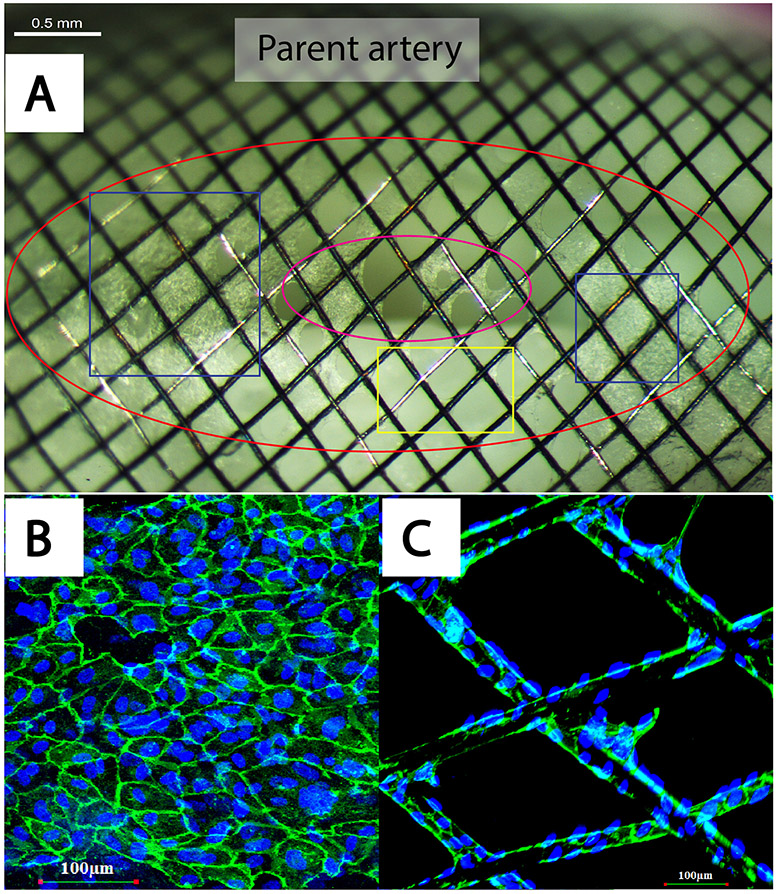
At 28 days, 1 of 3 samples had the device completely cross over the neck. The remaining two samples had device covering the majority of the neck orifice. Macroscopy demonstrated the entire parent vessel was covered with a translucent neointimal layer in two aBVMs; these two samples also had confluent tissue patches and/or interrupted tissue islands covering the device struts, as well as filling the pores between the struts over the neck (Figure 3). Confocal microscopy showed the luminal surface of the device struts located within the parent vessel was lined with a single layer of CD31+ cells. These confluent CD31+ cells lined the tissue patches/islands over the neck as well (Figure 4). SMA+ cells were identified underneath CD31+ cells at these areas. Overall, a higher degree of cellular coverage was observed on the struts and pores at the neck at 28 days compared to both 7 and 14 days (Table 1). The tissue coverage was not visible in one of the samples. It appeared that the cells did not grow well in that aBVM.
Figure 4.
FD implanted aBVM harvested at 28 days. (A) Gross image shows FD covered the aneurysm neck area (red circle). The blue squares show the confluent tissue patch completely covering the device struts and filling in the gap between pores. These areas are lined with a single layer of endothelial cells (green in panel B). The interrupted tissue islands/patch remain visible at the center of the neck (purple circle in panel A). Some struts in the neck are grossly bare (yellow rectangle in panel A), while they are wrapped with one layer of CD31 positive endothelial cells that are not completely confluent yet (C). (A) Macrophotograph. (B, C) Whole tissue mount immunofluorescence (CD31 (green) and DAPI nuclear counter stain (blue), laser confocal microscopy; original magnification=waterlens x20). aBVM, aneurysmlike blood vessel mimic; FD, flow diverter.
Discussion
Our study examining endothelialization of FDs in a tissue-engineered aneurysm model demonstrated that the endothelial cells migrate from the adjacent parent vessels in a centripetal fashion on the device struts to form a neointimal layer covering the neck in a time-dependent manner. Our findings in the tissue-engineered aneurysm model simulate the cellular responses to FDs found in the rabbit elastase aneurysms. These tissue-engineered aneurysm models created with saccular outpouching may provide an alternative tool for studying the biological effects of endovascular devices in the development of next-generation devices.
It has been shown that FDs promote thrombosis formation in the aneurysm sac, and simultaneous device endothelialization at the neck promotes occlusion of aneurysms from the parent vessel. Immediately following device placement, the endothelial layer is denuded in the parent vessel, at the location of device placement. The parent vessel is re-endothelialized by 7 days in a rabbit model, and device endothelialization occurs progressively over weeks to months. Edothelialization of FDs appeared to derive from cells in adjacent parental arteries5. Frosen et al. showed that the neointimal cells in the neck region were derived from the parent vessel, while in the aneurysm fundus the neointimal cells were derived from the aneurysm wall following endovascular treatment13.
There are many different benchtop aneurysm models available for assessing preclinical performances of endovascular devices. However, only a handful of in vitro models exists that are suitable for studying the biological aspects of aneurysms. Patient-specific 3D-printed endothelialized silicone aneurysm models have been used to correlate hemodynamic factors with endothelial gene expression14, 15. While these models offer physical compliance with some biological properties of the vessel wall, they are limited to endothelial cells, which are weakly attached to the silicon vessel wall and lack the intercellular communication between vascular tissue components. Our electrospun scaffold models are engineered with both endothelial and smooth muscle cells in 3-dimensional space, maintained in individual bioreactor systems coupled with peristaltic flow patterns imitating physiologic blood flow. This model is well suited for both qualitative and quantitative analysis of device attachment, and cellular proliferation and composition over specific device regions at multiple early time points following device implantation. Further, the use of electrospun PCL as the scaffold provides desirable structural and mechanical properties, having improved compliance with vessel wall mechanical characteristics over PLGA polymers that are routinely used in previous blood vessel mimic scaffolds11.
Currently, there is an unmet need for a physiologically relevant aneurysm system that can bridge the gaps between preclinical models and human aneurysms. The electrospinning fabrication technique can be modified to make a variety of scaffolds of pre-defined aneurysm geometries, including fusiform, bifurcation, bleb, or blister types7, 11. The ability to combine functional vascular cells in the lumen in the desired geometries coupled with the capacity to tweak the blood flow conditions would potentially allow researchers to use these aBMVs as an in vitro aneurysm model system for not only device testing but also for studying local wall shear stress and other hemodynamic changes16, 17. Further, bone marrow-derived endothelial progenitor or immuno precursor cells can also be added to the circulatory media to mimic the in vivo physiology. Additional studies are needed to further characterize the model for other imaging applications.
Limitations
This study had several limitations: 1) the sample size was small; 2) the “aneurysm size” utilized in this study was relatively small compared to human intracranial aneurysms; 3) this study was limited to steady flow, low-pressure conditions, instead of physiologic flow rates and pressure, which will be applied in future studies to mimic the blood vessel hemodynamics; 4) a few cells covering the device at the neck of aBVMs were positive for both CD31 and SMA indicating the potential transition of endothelial cells to mesenchymal phenotypes in response to the local shear stress, which could be alleviated by closed-loop flow models18; 5) a few of the aBVMs did not have complete device coverage across the neck due to device migration, which is commonly observed in clinical settings. The use of oversized devices could minimize the device migration; 6) as with most in vitro models, this tissue-engineered model does not fully recapitulate the in vivo environment, especially the tissue responses to endovascular implants. Future work will include co-treatment with factors involved in endovascularly treated aneurysm healing.
Conclusion
The pattern of cellular response to FDs with the tissue-engineered aneurysm model mimics a similar pattern demonstrated with an in vivo, elastase-induced rabbit aneurysm model. These aBVMs show promise as a valuable alternative tool for the evaluation of a new generation of FDs and other endovascular devices prior to animal or patient trials.
Supplementary Material
Acknowledgments
We thank Medtronic Neurovascular (Irvine, Calif) for generously providing the flow diverters for this study. We also thank Dr. Jennifer Ayers-Ringler for her careful reading of the manuscript.
Funding Statement
This work was supported by National Institutes of Health grant number NS076491.
Footnotes
Competing Interests Statement
Rhere are no competing interests for any author.
Data Sharing
Data are available upon reasonable request.
References
- 1.Lozupone E, Piano M, Valvassori L, et al. Flow diverter devices in ruptured intracranial aneurysms: a single-center experience. J Neurosurg 2018;128:1037–1043 [DOI] [PubMed] [Google Scholar]
- 2.Hanel RA, Kallmes DF, Lopes DK, et al. Prospective study on embolization of intracranial aneurysms with the pipeline device: the PREMIER study 1 year results. J Neurointerv Surg 2020;12:62–66 [DOI] [PMC free article] [PubMed] [Google Scholar]
- 3.Becske T, Brinjikji W, Potts MB, et al. Long-Term Clinical and Angiographic Outcomes Following Pipeline Embolization Device Treatment of Complex Internal Carotid Artery Aneurysms: Five-Year Results of the Pipeline for Uncoilable or Failed Aneurysms Trial. Neurosurgery 2017;80:40–48 [DOI] [PubMed] [Google Scholar]
- 4.Petr O, Brinjikji W, Cloft H, et al. Current Trends and Results of Endovascular Treatment of Unruptured Intracranial Aneurysms at a Single Institution in the Flow-Diverter Era. Am J Neuroradiol 2016;37:1106–1113 [DOI] [PMC free article] [PubMed] [Google Scholar]
- 5.Kadirvel R, Ding YH, Dai D, et al. Cellular mechanisms of aneurysm occlusion after treatment with a flow diverter. Radiology 2014;270:394–399 [DOI] [PMC free article] [PubMed] [Google Scholar]
- 6.Li ZF, Fang XG, Yang PF, et al. Endothelial progenitor cells contribute to neointima formation in rabbit elastase-induced aneurysm after flow diverter treatment. CNS Neurosci Ther 2013;19:352–357 [DOI] [PMC free article] [PubMed] [Google Scholar]
- 7.Villadolid C, Puccini B, Dennis B, et al. Custom tissue engineered aneurysm models with varying neck size and height for early stage in vitro testing of flow diverters. J Mater Sci Mater Med 2020;31:34. [DOI] [PMC free article] [PubMed] [Google Scholar]
- 8.Chavez RD, Walls SL, Cardinal KO. Tissue-engineered blood vessel mimics in complex geometries for intravascular device testing. PLoS One 2019;14:e0217709. [DOI] [PMC free article] [PubMed] [Google Scholar]
- 9.Bonnema GT, Cardinal KO, McNally JB, et al. Assessment of blood vessel mimics with optical coherence tomography. J Biomed Opt 2007;12:024018. [DOI] [PubMed] [Google Scholar]
- 10.Cardinal KO, Williams SK. Assessment of the intimal response to a protein-modified stent in a tissue-engineered blood vessel mimic. Tissue Eng Part A 2009;15:3869–3876 [DOI] [PubMed] [Google Scholar]
- 11.Shen TW, Puccini B, Temnyk K, et al. Tissue-engineered aneurysm models for in vitro assessment of neurovascular devices. Neuroradiology 2019;61:723–732 [DOI] [PubMed] [Google Scholar]
- 12.Dai D, Ding YH, Rezek I, et al. Characterizing patterns of endothelialization following coil embolization: a whole-mount, dual immunostaining approach. J Neurointerv Surg 2016;8:402–406 [DOI] [PMC free article] [PubMed] [Google Scholar]
- 13.Frosen J, Marjamaa J, Myllarniemi M, et al. Contribution of mural and bone marrow-derived neointimal cells to thrombus organization and wall remodeling in a microsurgical murine saccular aneurysm model. Neurosurgery 2006;58:936–944; discussion 936-944 [DOI] [PubMed] [Google Scholar]
- 14.Levitt MR, Mandrycky C, Abel A, et al. Genetic correlates of wall shear stress in a patient-specific 3D-printed cerebral aneurysm model. J Neurointerv Surg 2019;11:999–1003 [DOI] [PMC free article] [PubMed] [Google Scholar]
- 15.Kaneko N, Mashiko T, Namba K, et al. A patient-specific intracranial aneurysm model with endothelial lining: a novel in vitro approach to bridge the gap between biology and flow dynamics. J Neurointerv Surg 2018;10:306–309 [DOI] [PubMed] [Google Scholar]
- 16.Salimi Ashkezari SF, Mut F, Chung BJ, et al. Hemodynamic conditions that favor bleb formation in cerebral aneurysms. J Neurointerv Surg 2020 [DOI] [PMC free article] [PubMed] [Google Scholar]
- 17.Samaniego EA, Roa JA, Hasan D. Vessel wall imaging in intracranial aneurysms. J Neurointerv Surg 2019;11:1105–1112 [DOI] [PubMed] [Google Scholar]
- 18.Arba F, Leigh R, Inzitari D, et al. Blood-brain barrier leakage increases with small vessel disease in acute ischemic stroke. Neurology 2017;89:2143–2150 [DOI] [PMC free article] [PubMed] [Google Scholar]
Associated Data
This section collects any data citations, data availability statements, or supplementary materials included in this article.


